Loading ...
Loading ...
Loading ...
PRODUCT DATA | 25
Product Data
'XHWRRXUSROLF\RIFRQWLQXRXVSURGXFWLQQRYDWLRQVRPHVSHFL¿FDWLRQVPD\FKDQJHZLWKRXWQRWL¿FDWLRQ
©
/*(OHFWURQLFV86$,QF(QJOHZRRG&OLIIV1-$OOULJKWVUHVHUYHG³/*´LVDUHJLVWHUHGWUDGHPDUNRI/*&RUS
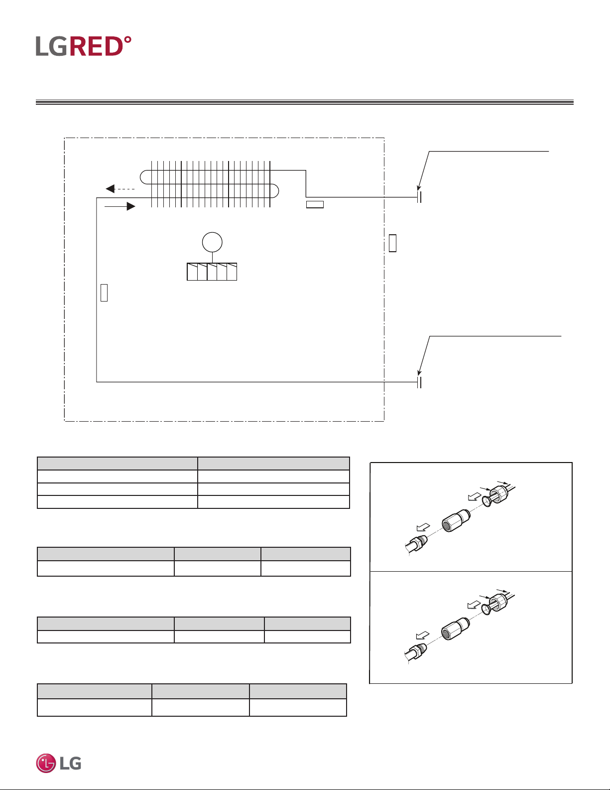
REFRIGERANT FLOW DIAGRAMS
Table 12: LCN188HV4 Four-Way Ceiling Cassette Indoor Unit Thermistor Details.
Model No. Vapor (inch) Liquid (inch)
LCN188HV4 1/2 1/4
Table 13: LCN188HV4 Four-Way Ceiling Cassette Indoor Unit Refrigerant Pipe
Connections.
Description (Based on Cooling Mode) PCB Connector
Indoor Air Temperature Thermistor CN-ROOM
Evaporator Inlet Temperature Thermistor CN-PIPE / IN
Evaporator Outlet Temperature Thermistor CN-PIPE / OUT
Heat exchanger
Gas pipe connection port
(flare connection)
Liquid pipe connection port
(flare connection)
Turbo fan
Cooling
Heating
M
Indoor Air
Temperature Thermistor
Evaporator Inlet
Temperature Thermistor
Evaporator Outlet
Temperature Thermistor
Figure 18: LCN188HV4 Refrigerant Flow Diagram.
LCN188HV4 Indoor Units
Table 14: LCN188HV4 Four-Way Ceiling Cassette Indoor Unit Refrigerant Pipe Sizes.
Model No. Vapor (inch) Liquid (inch)
LCN188HV4 5/8 3/8
Table 15: LCN188HV4 Connection Socket Dimensions.
Model No. Vapor (inch) Liquid (inch)
LCN188HV4 Ø1/2 – Ø5/8 Ø1/4 – Ø3/8
Figure 19: LCN188HV4 Refrigerant Pipe Connections.
1/2 in. to 5/8 in.
Connection
Ø5/8 in.
Connection socket
Flare nut
Piping
Ø1/2 in.
1/4 in. to 3/8 in.
Connection
Flare side to indoor unit
Ø3/8 in.
Connection socket
Flare nut
Piping
Ø1/4 in.
Flare side to indoor unit
Flare
side pipe
from ODU
Flare
side to
ODU
Loading ...
Loading ...
Loading ...