
owner's
manual
MODEL NO.
247.886510
CAUTION:
Read
INSTRUCTIONS
carefully
_/-___/_R,_/ CRRFT$MRN®
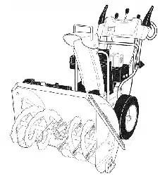
23" - 5 H.P. DUAL STAGE
SNOW THROWER
Optional Electric Starter Available
=Assembly
=Operation
=Maintenance
=Repair Parts
Sold by Sears, Roebuck and Co., Chicago, IL 60684
Part No. 770-6870D
CRAFTSMAN WARRANTY'
LIMITED TWO YEAR WARRANTY ON CRAI_SMAN SNOW THROWER
For two years from the date of purchase, whet this Craftsman Snow Thrower is maintained, lubricated and tuned up
according to the instructions in the owner's manual, Sears will repair, free of charge, any defect in material and
workmanship.
If this Craftsman Snow Thrower is used for c<;mmercial or rental purposes, this warranty applies for only 90 days from
the date of purchase.
This warranty does not cover: Expendable terns which become worn during normal use, such as spark plugs, tire
chains and shear pins.
Repairs necessary because of operator aLuse or negligence, including bent cranksh_,ffs and the failure to maintain
the equipment according to the instructk ns contained in the owner's manual.
WARRANTY SERVICE IS AVAILABLE BY CO _ITACTING THE NEAREST SERVICE CENTER/DEPARTMENT IN THE
UNITED STATES. This warranty applies only while this product is in use in the United States.
This warranty gives you specific legal rights, and you may also have other rights which vary from state to state.
SEARS, ROEBUCK AND CO.
DEP' r. 698/731A SEARS TOWER
CHICAGO, IL 60684
OWNEF:'S INFORMATION
Record the following information about youl unit so that you will be able to provide it in case of loss or theft.
DATE PURCHASED:. MODEL NO./CODE: 247.886510L
STORE WHERE PURCHASED: ADDRES_
CITY: STATE: TELEPHONE:
MAINTENANCE AGREEMENT
A SEARS MAINTENANCE AGREEMENT IS AVAILABLE FOR THIS PRODUCT. CONTACT YOUR NEAREST
SEAR S STORE FOR DETAILS.
TABLF OF CONTENTS
Page
CRAFTSMAN WARRANTY ................. 2
OWNER'S INFORMATION .................. 2
MAINTENANCE AGREEMENT .............. 2
SAFE OPERATION PRACTICES ............. 3
ASSEMBLY INSTRUCTIONS .............. 4-9
OPERATING INSTRUCTIONS ........... 10-13
MAINTENANCE ..................... 13, 14
Page
STORAGE ........................... 14, 15
ADJUSTMENT/REPAIRS ............... 15-19
TROUBLE SHOOTING GUIDE ............. 20
SNOW THROWER REPAIR PARTS ...... 22-29
ENGINE REPAIR PARTS ............... 30-34
HOW TO ORDER REPAIR PARTS .. Back Cover
IMPOR ANT
SAFE OPERATION PRACTICES FOR WALK-BEHIND SNOW THROWERS
_lb THIS SYMBOL POINTS OUT IMPORTANT SAFETY INSTRUCTIONS WHICH, IF NOT FOLLOWED COULD
ENDANGER
THE PERSONAL SAFETY AND/OR PROPERTY OF YOURSELF AND OTHERS. READ AND
FOLLOW ALL INSTRUCTIONS IN THIS MANUAL BEFORE ATTEMPTING TO OPERATE YOUR SNOW
THROWER.
To reduce the potential for any injury, comply with the following safety instructions. Failure to comp|y with
the instructions may result in personal injury.
TRAINING
1. Read this owner's guide carefully. Be thoroughly familiar with
the controls and proper use of the equipment. Know how to
stop the unit and disengage the controls quickly.
2. Never allow children to operate equipment. Never allow
adults to operate equipment without proper instructions.
3. No one should operate this unit while intoxicated or while
taking medication that impairs the senses or reactions.
4. Keep the area of operation clear of all persons, especialLy
small children and pets.
5. Exercise caution to avoid slipping or falling, especially when
operating in reverse.
PREPARATION
1. Thoroughly inspect the area where the equipment is to be
used and remove all door mats, sleds, boards, wires and
other foreign objects.
2. Disengage all clutches and shift into neutral before starting
engine.
3. Do not operate equipment without wearing adequate winter
outer garments. Wear footwear which will improve footing
on slippery surfaces.
4. Check the fuel before starting the engine. Gasoline is an ex-
tremely flammable fuel. Do not fill the gasoline tank indoors,
while the engine is running, or while the engine is still hot.
Replace gasoline cap securely and wipe off any spilled
gasoline before starting the engine as it may cause_a fire or
explosion.
5. Use a grounded three wire plug-in for all units with electric
drive motors or etectric starting motors.
6. Adjust auger housing height to clear gravel or crushed rock
surface.
7. Never attempt to make any adjustments while engine is run-
ning (except where specifically recommended by
manufacturer).
8. Let engine and machine adjust to outdoor temperature before
starting to clear snow.
9. Always wear safety glasses or eye shields during operation
or while performing an adjustment or repair, to protect eyes
from foreign objects that may be thrown from the machine
in any direction.
OPERATION
1, Do not put hands or feet near rotating parts. Keep clear of
discharge opening at all times.
2. Exercise extreme caution when operating on or crossing
gravel drives, walks, or roads. Stay alert for hidden hazards
or traffic. Do not carry passengers.
3. After striking a foreign object, stop the engine, remove wire
from spark plug, and thoroughly inspect the snow thrower
for any damage. Repair the damage before restarting and
operating the snow thrower.
4. If the snow thrower should start to vibrate abnormally, stop
the engine and check immediately for the cause. Vibration
is generally a warning of trouble.
12.
13.
14.
15.
16.
5_ Stop engine whenever you leave the operating position,
before unclogging the augerlimpel_,r housing or discharge
guide, and making any repairs, adjustments, or inspections.
6. Take all possible precautions when leaving the unit un-
attended. Disengage the auger/impeller, shift into neutral,
stop the engine, and remove the key.
7. When cleaning, repairing, or inspecting, make certain
auger/impeller and all moving parts have stopped. Discon-
nect spark plug wire and keep away from plag to prevent
accidental starting.
8. Do not run engine indoors, except when starting engine and
transporting snow thrower in or out of building. Open doors.
Exhaust fumes are dangerous.
9. Do not clear snow across the face of slopes. Exercise ex-
treme caution when changing direction on slopes. Do not at-
tempt to clear steep slopes.
10. Never operate snow thrower without guards, plates, or other
safety protection devices in place.
11. Never operate snow thrower near glass enclosures,
automobiles, windows wells, drop offs, etc., without proper
adjustment of snow thrower discharge angle. Keep children
and pets away.
Do not overload machine capacity by attempting to clear
snow at too fast a rate.
Never operate the machine at high transport speeds on slip-
pery surfaces. Look behind and use care when backing.
Never direct discharge at bystanders or allow anyone in front
of unit.
17.
Disengage power to auger/impeller when transporting or not
in use.
Use only attachments and accessories approved by the
manufacturer of snow thrower (such as wheel weights,
counterweights, cabs, etc.).
Never operate the snow thrower without good visibility or light.
Always be sure of your footing and keep a firm hold on the
handles. Walk, never run.
MAINTENANCE AND STORAGE
1. Check shear bolts, engine mounting bolts, etc., at frequent
intervals for proper tightness to be sure equipment is in safe
working condition.
2. Never store the machine with fuel in the fuel tank inside a
building where ignition sources are present, such as hot water
and space heaters, clothes dryers, and the like. Allow engine
to cool before storing in any enclosure.
3. Always refer to owner's manual instructions for important
details if snow thrower is to be stored for an extended period.
4. Maintain or replace safety and instruction labels, as
necessary.
5. Run machine a few minutes after throwing snow to prevent
freeze up of auger/impeller.
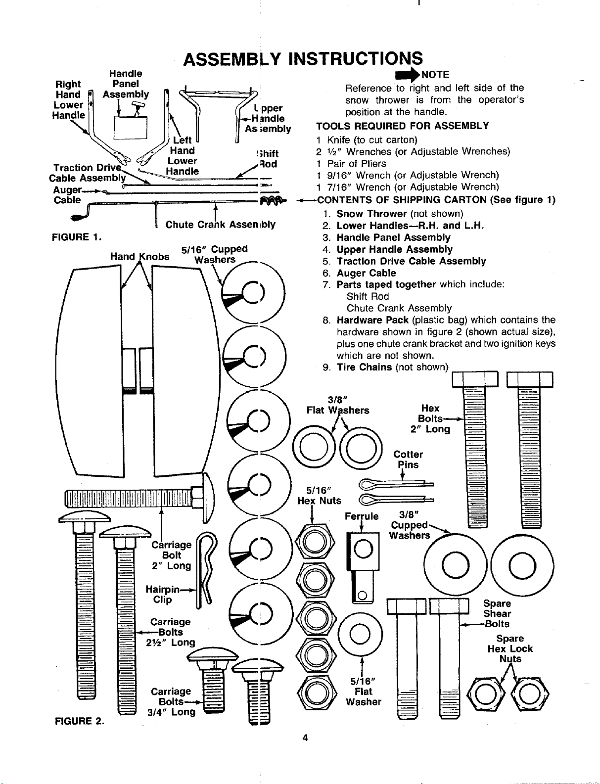
ASSEMBLY INSTRUCTIONS
Handle
Right Panel , .
Hand P] Assembly _ _-====_==,_1_
Lower
Han_dleI1 [L_ I_ "_ _'HL PPd_r
\\t_s JJ e,,
"_.'_ ._',F Hand !;hift
Traction Driv__'_ _ h_nw_ /:iod
Cable Assembly__ _ L _=_
Augers,
Cable
FIGURE 1.
I Chute Cra!k Assembly
Hand Knobs
5/16" Cupped
Wa _ers
I1_ NOT E
Reference to right and left side of the
snow thrower is from the operator's
position at the handle.
TOOLS REQUIRED FOR ASSEMBLY
1 Knife (to cut carton)
2 1/2" Wrenches (or Adjustable Wrenches)
1 Pair of Pliers
1 9/16" Wrench (or Adjustable Wrench)
1 7/16" Wrench (or Adjustable Wrench)
--_---CONTENTS OF SHIPPING CARTON (See figure 1)
1. Snow Thrower (not shown)
2. Lower Handles--R.H. and L.H.
3. Handle Panel Assembly
4. Upper Handle Assembly
5. Traction Drive Cable Assembly
6. Auger Cable
7. Parts taped together which include:
Shift Rod
Chute Crank Assembly
8. Hardware Pack (plastic bag) which contains the
hardware shown in figure 2 (shown actual size),
plus one chute crank bracket and two ignition keys
which are not shown.
9. Tire Chains (not shown)
E q q
FIGURE 2.
rriage
Bolt
2" Long
Clip
Carriage
Its
21/2" Long
Carriage
3/4" Long
5/16"
Flat
Washer
Bolts----_
2" Long
Cotter
ins
I
3/8"
--LJ Spare
Shear
_---Bolts
Spare
Hex Lock
I
Upper
Chute
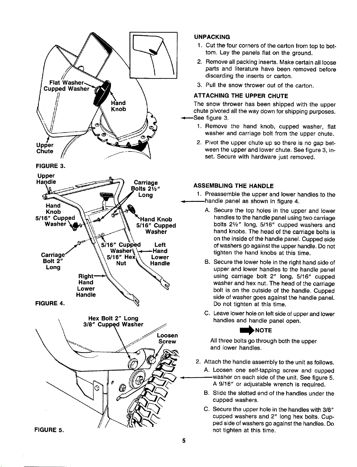
FIGURE 3.
Upper
Hand
Knob
5/16"
Carria
Bolt 2"
Long
Ri
Hand
Lower
Handle
FIGURE 4.
Carriage
Bolts 21/2"
Long
Knob
5/16" Cupped
Washer
Left
washer_ k_-..-Hand
5/16" Hex_.\ Lower
Nut _
Hex Bolt 2" Long
318" d Washer
Loosen
Screw
UNPACKING
1. Cut the four corners of the carton from top to bot-
tom. Lay the panels flat on the ground.
2. Remove all packing inserts. Make certain all loose
parts and literature have been removed before
discarding the inserts or carton.
3. Pull the snow thrower out of the carton.
ATTACHING THE UPPER CHUTE
The snow thrower has been shipped with the upper
chute pivoted all the way down for shipping purposes.
-.,_----See figure 3.
1, Remove the hand knob, cupped washer, fiat
washer and carriage bolt from the upper chute.
2. Pivot the upper chute up so there is no gap bet-
ween the upper and lower chute. See figure 3, in-
set. Secure with hardware just removed.
ASSEMBLING THE HANDLE
1. Preassemble the upper and lower handles to the
.d------handle panel as shown in figure 4.
A. Secure the top holes in the upper and lower
handles to the handle panel using two carriage
bolts 21/2" long, 5!16" cupped washers and
hand knobs. The head of the carriage bolts is
on the inside ofthe handle panel. Cupped side
of washers go against the upper handle. Do not
tighten the hand knobs at this time.
B. Secure the lower hole in the right hand side of
upper and lower handles to the handle panel
using carriage bolt 2" long, 5/16" cupped
washer and hex nut. The head of the carriage
bolt is on the outside of the handle. Cupped
side of washer goes against the handle panel.
Do not tighten at this time.
C. Leave lower hole on left side of upper and lower
handles and handle panel open.
I_NOTE
All three bolts go through both the upper
and lower handles.
FIGURE 5.
2. Attach the handle assembly to the unit as follows.
A. Loosen one self-tapping screw and cupped
.washer on each side of the unit. See figure 5.
A 9/16" or adjustable wrench is required.
B. Slide the slotted end of the handles under the
cupped washers.
C. Secure the upper hole in the handles with 318"
cupped washers and 2" long hex bolts. Cup-
ped side of washers go against the handles. Do
not tighten at this time.
EyeboIt
Crank
Assembly
5116"
Hex Nui s
5/16" Cupped
Washer
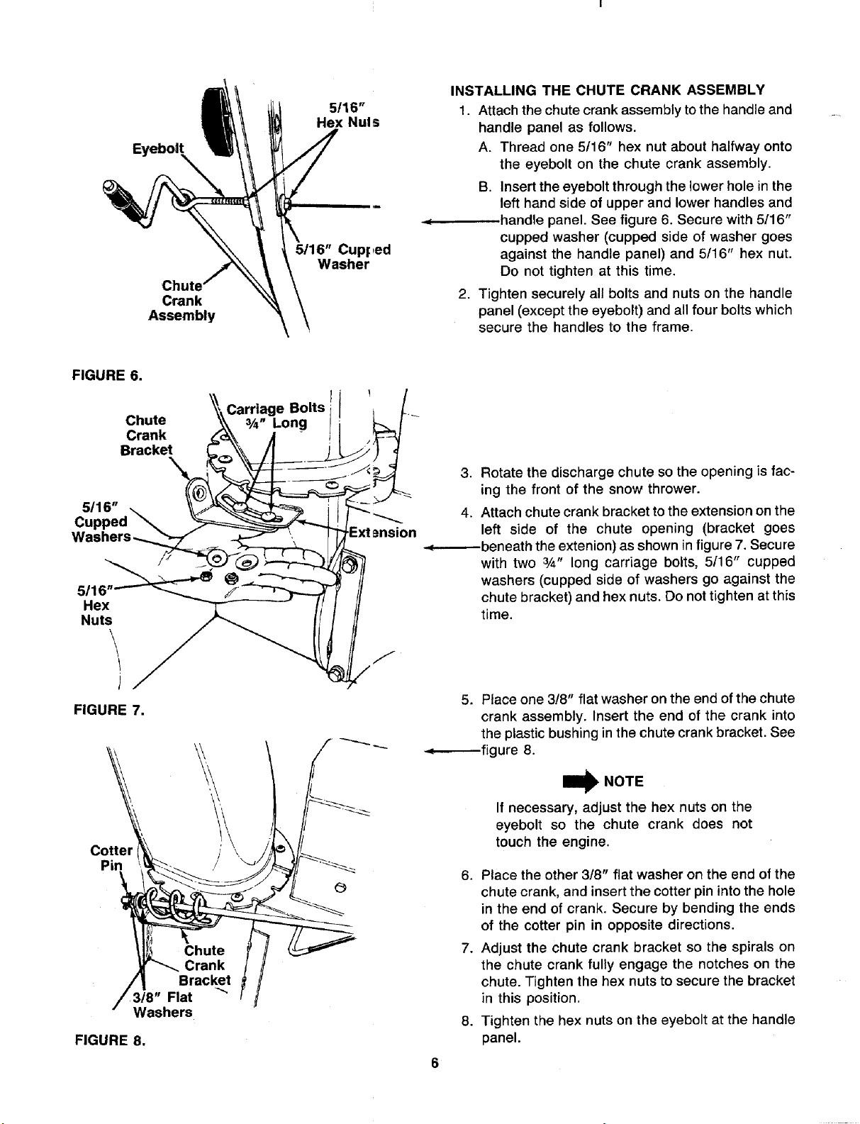
INSTALLING THE CHUTE CRANK ASSEMBLY
1. Attach the chute crank assembly to the handle and
handle panel as follows.
A. Thread one 5/16" hex nut about halfway onto
the eyebolt on the chute crank assembly.
B. Insert the eyebolt through the lower hole in the
left hand side of upper and lower handles and
handle panel. See figure 6. Secure with 5/16"
cupped washer (cupped side of washer goes
against the handle panel) and 5/16" hex nut.
Do not tighten at this time.
2. Tighten securely all bolts and nuts on the handle
panel (except the eyebolt) and all four bolts which
secure the handles to the frame.
FIGURE 6.
Chute
Crank
Bracket
Carriage Bolts
3/_" Long
5116"
Cur
5116
Hex
Nuts
\
J
FIGURE 7.
Cotter _\ /'\ _/j_'_/_
• Washers
FIGURE 8.
3. Rotate the discharge chute so the opening is fac-
ing the front of the snow thrower.
4. Attach chute crank bracket to the extension on the
left side of the chute opening (bracket goes
-.(---_--beneath the extenion) as shown in figure 7. Secure
with two 3/4" long carriage bolts, 5116" cupped
washers (cupped side of washers go against the
chute bracket) and hex nuts. Do not tighten at this
time.
5. Place one 318" flat washer on the end of the chute
crank assembly. Insert the end of the crank into
the plastic bushing in the chute crank bracket. See
-.,_-----fig ure 8.
W NOTE
If necessary, adjust the hex nuts on the
eyebolt so the chute crank does not
touch the engine.
6. Place the other 3/8" flat washer on the end of the
chute crank, and insert the cotter pin into the hole
in the end of crank. Secure by bending the ends
of the cotter pin in opposite directions.
7. Adjust the chute crank bracket so the spirals on
the chute crank fully engage the notches on the
chute. Tighten the hex nuts to secure the bracket
in this position.
8. Tighten the hex nuts on the eyebolt at the handle
panel.
Shift
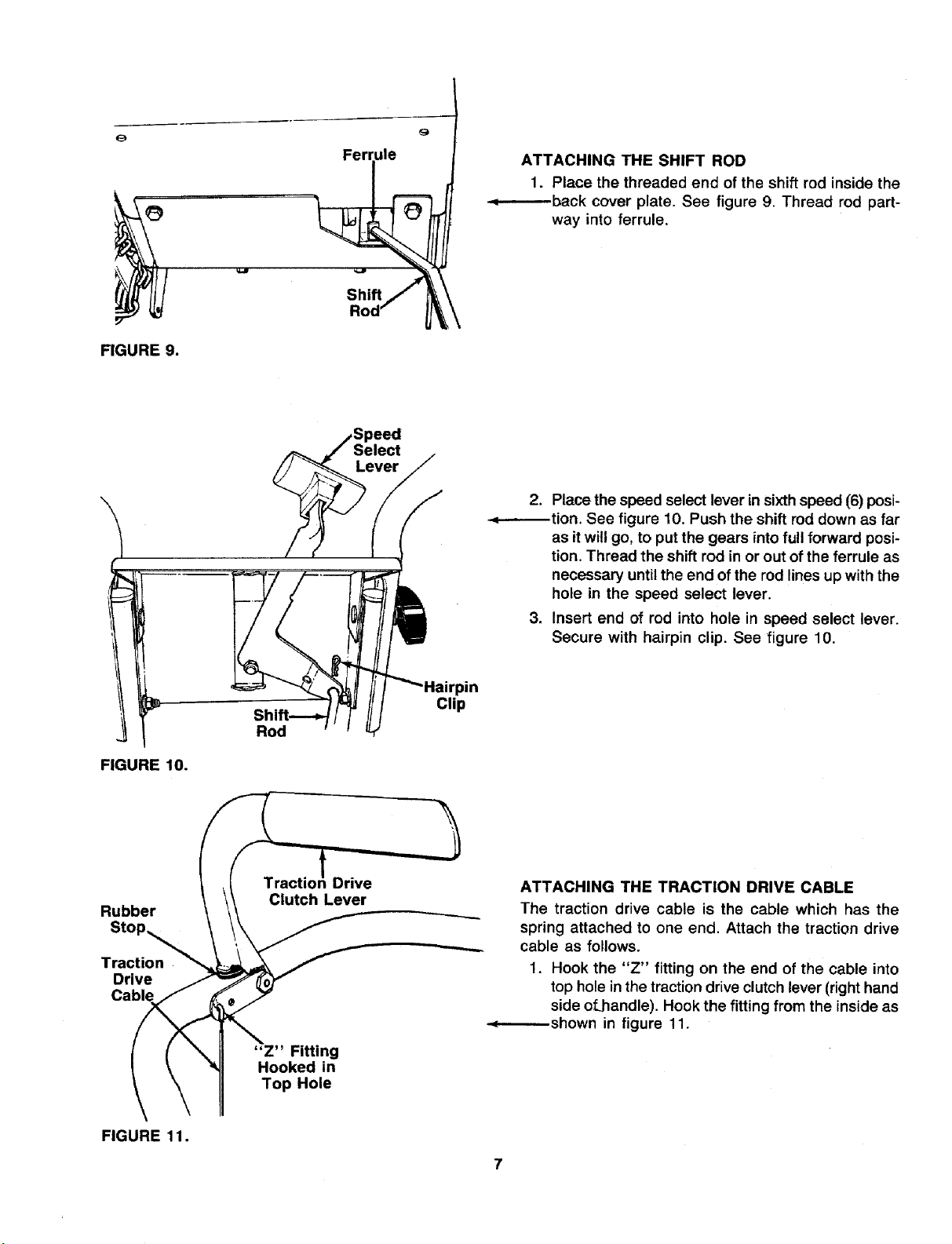
ATTACHING THE SHIFT ROD
1. Place the threaded end of the shift rod inside the
-.q-------.-back cover plate. See figure 9. Thread rod part-
way into ferrule.
FIGURE 9.
FIGURE 10.
Rod
2. Place the speed select lever Lnsixthspeed (6) posi-
_tion. See figure 10. Push the shift rod down as far
as itwill go, to put the gears intofull forward posi-
tion. Thread the shift rod in or out of the ferrule as
necessary until the end ofthe rod lines up with the
hole in the speed select lever.
3. Insert end of rod into hole in speed select lever.
Secure with hairpin clip. See figure 10.
pin
Clip
Rubber
Stop_
Traction
Drive
Cable
Drive
Clutch Lever
"Z" Fitting
Hooked in
Top Hole
ATTACHING THE TRACTION DRIVE CABLE
The traction drive cable is the cable which has the
spring attached to one end. Attach the traction drive
cable as follows.
1. Hook the "Z" fitting on the end of the cable into
top hole inthe traction drive clutch lever (righthand
side of.handle). Hook the fitting from the inside as
•._-..-----shown in figure 11.
FIGURE 11.
LineUpCenter
of HookWith
Centerof Hole
FIGURE12.
Lengthl
Traction
Dri_!e
Cal0te
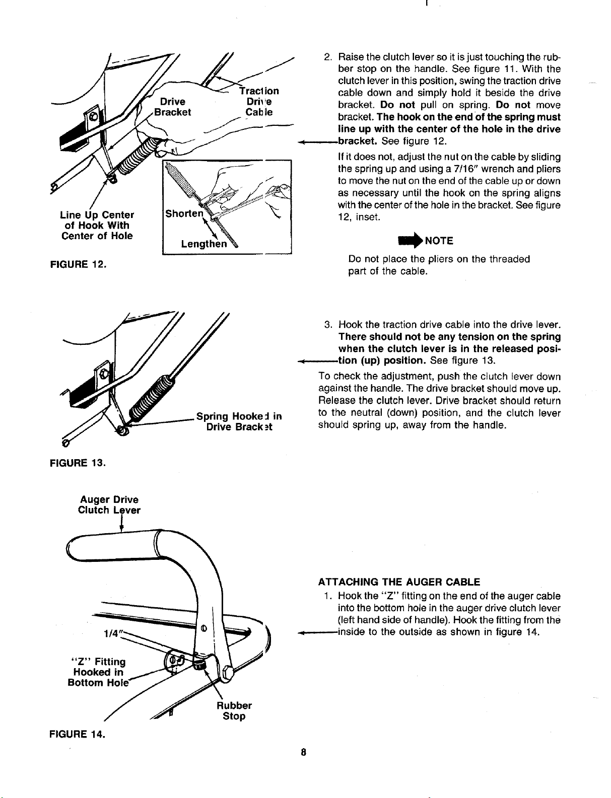
2. Raise the clutch lever so it is just touching the rub-
ber stop on the handle. See figure 11. With the
clutch lever in this position, swing the traction drive
cable down and simply hold it beside the drive
bracket. Do not pull on spring. Do not move
bracket. The hook on the end of the spring must
line up with the center of the hole in the drive
-._--.------bracket. See figure 12.
If itdoes not, adjust the nut on the cable by sliding
the spring up and using a 7116" wrench and pliers
to move the nut on the end ofthe cable up or down
as necessary until the hook on the spring aligns
with the center ofthe holein the bracket. See figure
12, inset.
Do not place the pliers on the threaded
part of the cable.
Hooke _ in
Drive Brack _=t
3. Hook the traction drive cable into the drive lever.
There should not be any tension on the spring
when the clutch lever is in the released posi-
-.,_-_--tion (up) position. See figure 13.
To check the adjustment, push the clutch lever down
against the handle. The drive bracket should move up.
Release the clutch lever. Drive bracket should return
to the neutral (down) position, and the clutch lever
should spring up, away from the handle.
FIGURE 13.
Auger Drive
Clutch Lever
1/4
"Z" Fitting
Hooked in
Bottom
FIGURE 14.
Rubber
Stop
ATTACHING THE AUGER CABLE
1. Hook the "Z" fitting on the end of the auger cable
intothe bottom hole in the auger drive clutch lever
(left hand side of handle). Hook the fitting from the
.,=----.---inside to the outside as shown in figure 14.
/
FIGURE 15.
Auger
Bracket
Cross
Chain
Chain
FIGURE 16.
Cotter
Flat
st
Cable
Link
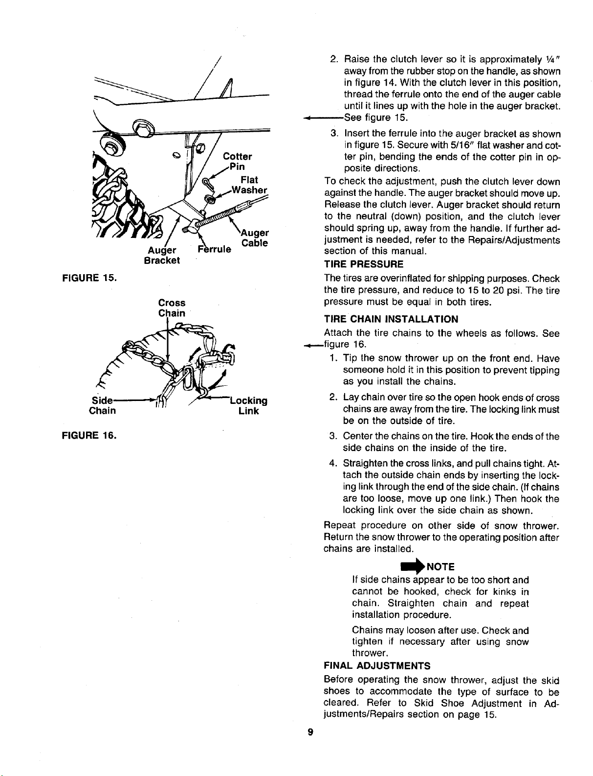
2. Raise the clutch lever so it is approximately 1/4"
away from the rubber stop on the handle, as shown
in figure 14. With the clutch lever in this position,
thread the ferrule onto the end of the auger cable
until it lines up with the hole in the auger bracket.
-.,--..------See figure 15.
3. Insert the ferrule into the auger bracket as shown
in figure 15. Secure with 5/16" flat washer and cot-
ter pin, bending the ends of the cotter pin in op-
posite directions.
To check the adjustment, push the clutch lever down
against the handle. The auger bracket should move up.
Release the clutch lever. Auger bracket should return
to the neutral (down) position, and the clutch lever
should spring up, away from the handle. If further ad-
justment is needed, refer to the Repairs/Adjustments
section of this manual.
TIRE PRESSURE
The tires are overinflated for shipping purposes. Check
the tire pressure, and reduce to 15 to 20 psi. The tire
pressure must be equal in both tires.
TIRE CHAIN INSTALLATION
Attach the tire chains to the wheels as follows. See
-+--figure 16.
1. Tip the snow thrower up on the front end. Have
someone hold it in this position to prevent tipping
as you install the chains.
2. Lay chain over tire sothe open hook ends of cross
chains are away from the tire. The lockinglink must
be on the outside of tire.
3. Center the chains on the tire. Hook the ends of the
side chains on the inside of the tire.
4. Straighten the cross links, and pull chains tight. At-
tach the outside chain ends by inserting the lock-
ing linkthrough the end of theside chain. (Ifchains
are too loose, move up one link.) Then hook the
locking link over the side chain as shown.
Repeat procedure on other side of snow thrower.
Return the snow thrower to the operating position after
chains are installed.
If side chains appear to be too short and
cannot be hooked, check for kinks in
chain. Straighten chain and repeat
installation procedure.
Chains may loosen after use. Check and
tighten if necessary after using snow
thrower.
FINAL ADJUSTMENTS
Before operating the snow thrower, adjust the skid
shoes to accommodate the type of surface to be
cleared. Refer to Skid Shoe Adjustment in Ad-
justments/Repairs section on page 15.
OPERATII G INSTRUCTIONS
1. STOP ENGINE BEFORE REMOVING DEBRIS
AND SERVICING UNIT
2. KEEP CLEAR OF IMPELLER WHILE ENGINE
IS RUNNING
3. NEVER DIRECT DISCHARGE AT BYSTANDERS
OR WINDOWS OR ALLOW ANYONE IN FROliT
OF UNIT
4. THOROUGHLY INSPECT THE AREA WHERE
THE EQUIPMENT IS TO BE USED AND
REMOVE ALL DOOR MATS, SLEDS, BOARD,*;,
WIRES AND OTHER FOREIGN OBJECTS
5. REFER TO OWNERS MANUAL FOR FULL
INSTRUCTIONS
W NOTE
Release the traction drive clutch lever
before shifting gears.
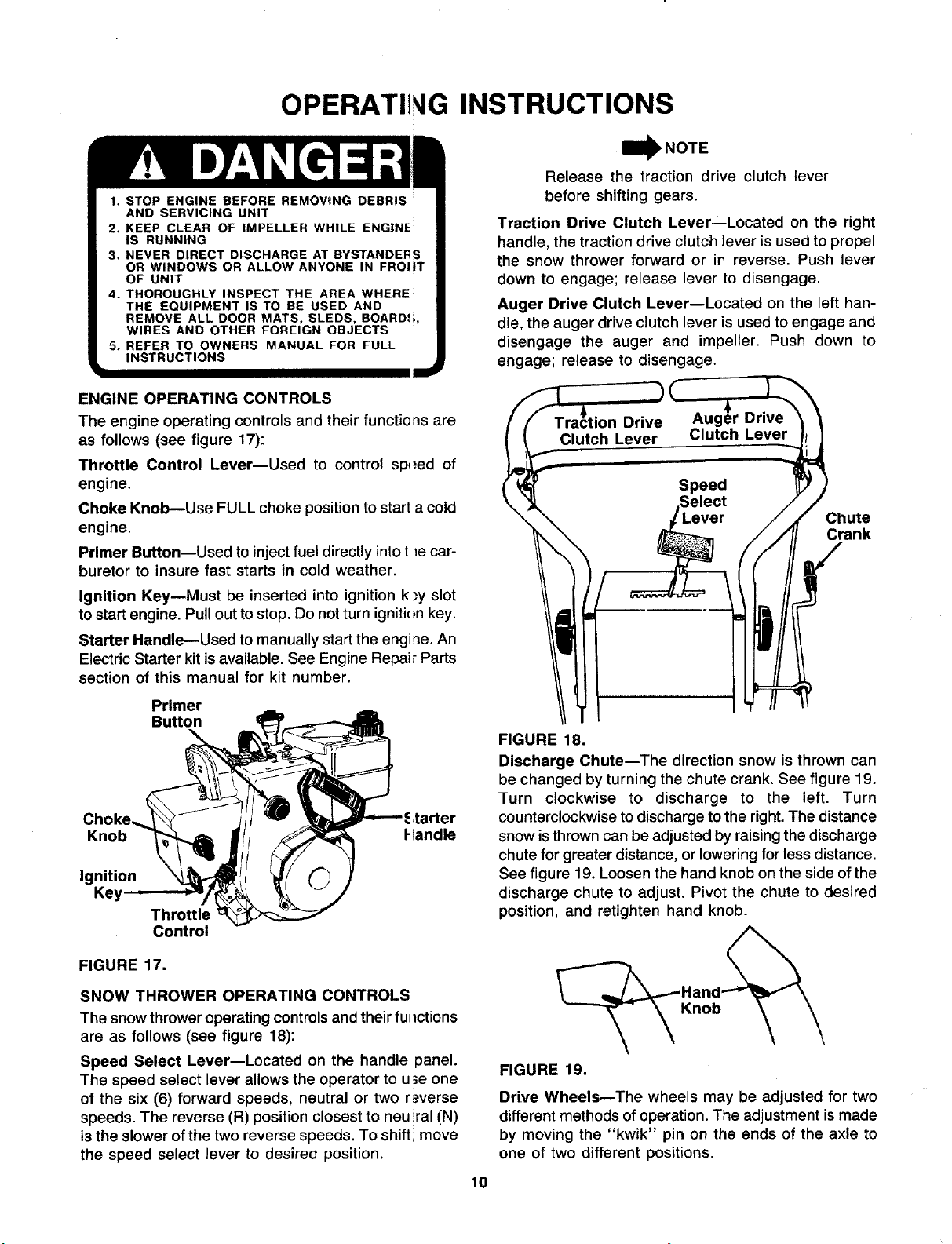
Traction Drive Clutch Lever--Located on the right
handle, the traction drive clutch lever is used to propel
the snow thrower forward or in reverse. Push lever
down to engage; release lever to disengage.
Auger Drive Clutch Lever--Located on the left han-
dle, the auger drive clutch lever is used to engage and
disengage the auger and impeller. Push down to
engage; release to disengage.
ENGINE OPERATING CONTROLS
The engine operating controls and their functions are
as follows (see figure 17):
Throttle Control LevermUsed to control sp,_ed of
engine.
Choke Knob--Use FULL choke position to start a cold
engine.
Primer Button--Used to injectfuel directly intot le car-
buretor to insure fast starts in cold weather.
Ignition Key--Must be inserted into ignition k,_yslot
to startengine. Pullout tostop. Do notturn igniti<_nkey.
Starter Handle--Used to manually start the engine. An
Electric Starter kit isavailable. See Engine Repair Parts
section of this manual for kit number.
Primer
Button
Knob I-tandle
Ignition
Key
Throttle
Control
FIGURE 17.
SNOW THROWER OPERATING CONTROLS
The snow thrower operating controlsand their furlctions
are as follows (see figure 18):
Speed Select Lever--Located on the handle panel.
The speed select lever allows the operator to u3e one
of the six (6) forward speeds, neutral or two r_=verse
speeds. The reverse (R) position closest to neu ;ral (N)
is the slower ofthe two reverse speeds. To shift; move
the speed select lever to desired position.
Chute
Crank
FIGURE 18.
Discharge Chute--The direction snow is thrown can
be changed by turning the chute crank. See figure 19.
Turn clockwise to discharge to the left. Turn
counterclockwise to discharge tothe right.The distance
snow isthrown can be adjusted by raisingthe discharge
chute for greater distance, or lowering for lessdistance.
See figure 19. Loosen the hand knob on the side ofthe
discharge chute to adjust. Pivot the chute to desired
position, and retighten hand knob.
Knob
FIGURE 19.
Drive Wheels--The wheels may be adjusted for two
different methods ofoperation. The adjustment ismade
by moving the "kwik" pin on the ends of the axle to
one of two different positions.
10
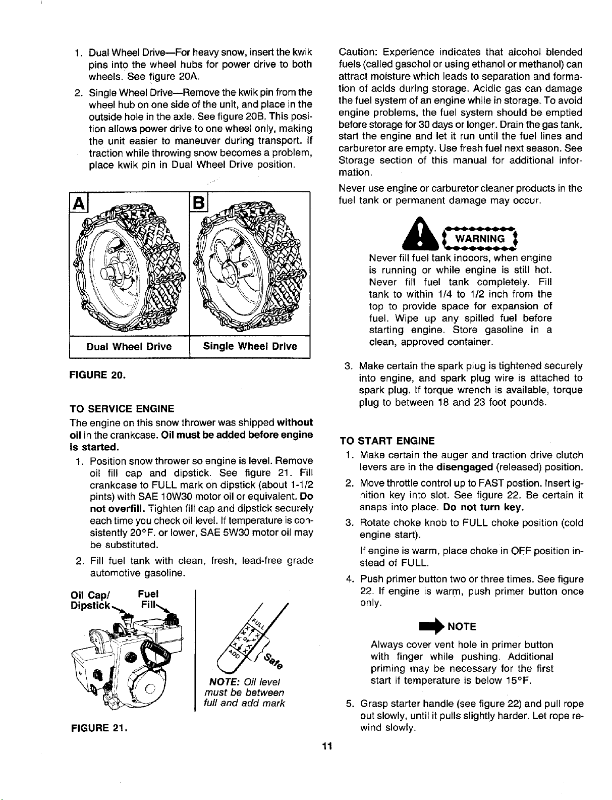
1. Dual Wheel Drive--For heavy snow, insert the kwik
pins into the wheel hubs for power drive to both
wheels. See figure 20A.
2. Single Wheel Drive--Remove the kwik pin from the
wheel hub on one side of the unit, and place in the
outside hole in the axle. See figure 20B. This posi-
tion allows power drive to one wheel only, making
the unit easier to maneuver during transport. If
traction while throwing snow becomes a problem,
place kwik pin in Dual Wheel Drive position.
Dual Wheel Drive Single Wheel Drive
FIGURE 20.
TO SERVICE ENGINE
The engine on this snow thrower was shipped without
oil in the crankcase. Oil must be added before engine
is started.
1. Position snow thrower so engine is level. Remove
oil fill cap and dipstick. See figure 21. Fill
crankcase to FULL mark on dipstick (about 1-1/2
pints) with SAE 10W30 motor oil or equivalent. Do
not overfill. Tighten fill cap and dipstick securely
each time you check oil level. Iftemperature iscon-
sistently 20°F. or lower, SAE 5W30 motor oil may
be substituted.
2. Fill fuel tank with clean, fresh, lead-free grade
automotive gasoline.
Oil Cap/ Fuel
Dipstick._ Fill_
_rliili O (_ _
NOTE: Oil level
must be between
full and add mark
FIGURE 21.
Caution: Experience indicates that alcohol blended
fuels (called gasohol or using ethanol or methanol) can
attract moisture which leads to separation and forma-
tion of acids during storage. Acidic gas can damage
the fuel system of an engine while in storage. To avoid
engine problems, the fuel system should be emptied
before storage for 30 days or longer. Drain the gas tank,
start the engine and let it run until the fuel lines and
carburetor are empty. Use fresh fuel next season. See
Storage section of this manual for additional infor-
mation.
Never use engine or carburetor cleaner products in the
fuel tank or permanent damage may occur.
Never fill fuel tank indoors, when engine
is running or while engine is still hot.
Never fill fuel tank completely. Fill
tank to within 1/4 to 1/2 inch from the
top to provide space for expansion of
fuel. Wipe up any spilled fuel before
starting engine. Store gasoline in a
clean, approved container.
.
Make certain the spark plug is tightened securely
into engine, and spark plug wire is attached to
spark plug. If torque wrench is available, torque
plug to between 18 and 23 foot pounds.
11
TO START ENGINE
1. Make certain the auger and traction drive clutch
levers are in the disengaged (released) position.
2. Move throttle control up to FAST postion. Insert ig-
nition key into slot. See figure 22. Be certain it
snaps into place. Do not turn key,
3. Rotate choke knob to FULL choke position (cold
engine start).
If engine is warm, place choke in OFF position in-
stead of FULL.
4. Push primer button two or three times. See figure
22. If engine is warm, push primer button once
only.
_)_ NOTE
Always cover vent hole in primer button
with finger while pushing. Additional
priming may be necessary for the first
start if temperature is below 15°F.
5. Grasp starter handle (see figure 22) and pull rope
out slowly, until it pulls slight!y harder. Let rope re-
wind slowly.
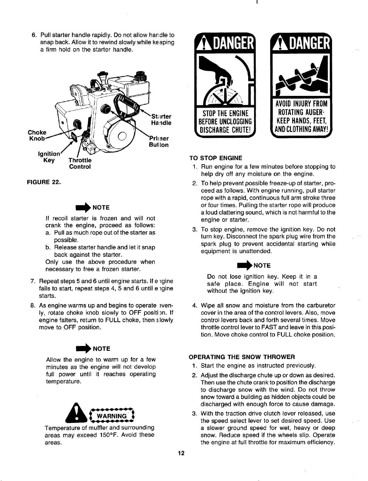
6. Pullstarterhandlerapidly.Donotallowhat,dieto
snapback.Allowittorewindslowlywhilekeeping
a firmholdonthestarterhandle.
Ha ndle
Choke
Knob kher
Bul _on
Ig
Key
FIGURE 22.
Throttle
Control
I_ NOTE
If recoil starter is frozen and will not
crank the engine, proceed as follows:
a. Pull as much rope out of the starter as
possible.
b. Release starter handle and let it snap
back against the starter.
Only use the above procedure when
necessary to free a frozen starter.
7. Repeat steps 5 and 6 until engine starts. If e lgine
fails to start, repeat steps 4, 5 and 6 until e lgine
starts.
8. As engine warms up and begins to operate ._ven-
ly, rotate choke knob slowly to OFF position. If
engine falters, return to FULL choke, then _lowly
move to OFF position.
I_ NOTE
Allow the engine to warm up for a few
minutes as the engine will not develop
full power until it reaches operating
temperature.
WARNING
Temperature of muffler and surrounding
areas may exceed 150°F. Avoid these
areas.
AVOIDINJURYFROM
ROTATINGAUGER-
KEEPHANDS,FEET,
ANDCLOTHINGAWAY
zz
TO STOP ENGINE
1. Run engine for a few minutes before stopping to
help dry off any moisture on the engine.
2. To help prevent possible freeze-up of starter, pro-
ceed as follows. With engine running, pull starter
rope with a rapid, continuous full arm stroke three
or four times. Pulling the starter rope will produce
a loud clattering sound, which is not harmful to the
engine or starter.
3. To stop engine, remove the ignition key. Do not
turn key. Disconnect the spark plug wire from the
spark plug to prevent accidental starting while
equipment is unattended.
W NOTE
Do not lose ignition key. Keep it in a
safe place. Engine will not start
without the ignition key.
4. Wipe all snow and moisture from the carburetor
cover in the area of the control levers. Also, move
control levers back and forth several times. Move
throttle control lever to FAST and leave in this posi-
tion. Move choke control to FULL choke position.
12
OPERATING THE SNOW THROWER
1. Start the engin e as instructed previously.
2. Adjust the discharge chute up or down as desired.
Then use the chute crank to position the discharge
to discharge snow with the wind. Do not throw
snow toward a building as hidden objects could be
discharged with enough force to cause damage.
3. With the traction drive clutch lever released, use
the speed select lever to set desired speed. Use
a slower ground speed for wet, heavy or deep
snow. Reduce speed if the wheels slip. Operate
the engine at full throttle for maximum efficiency.
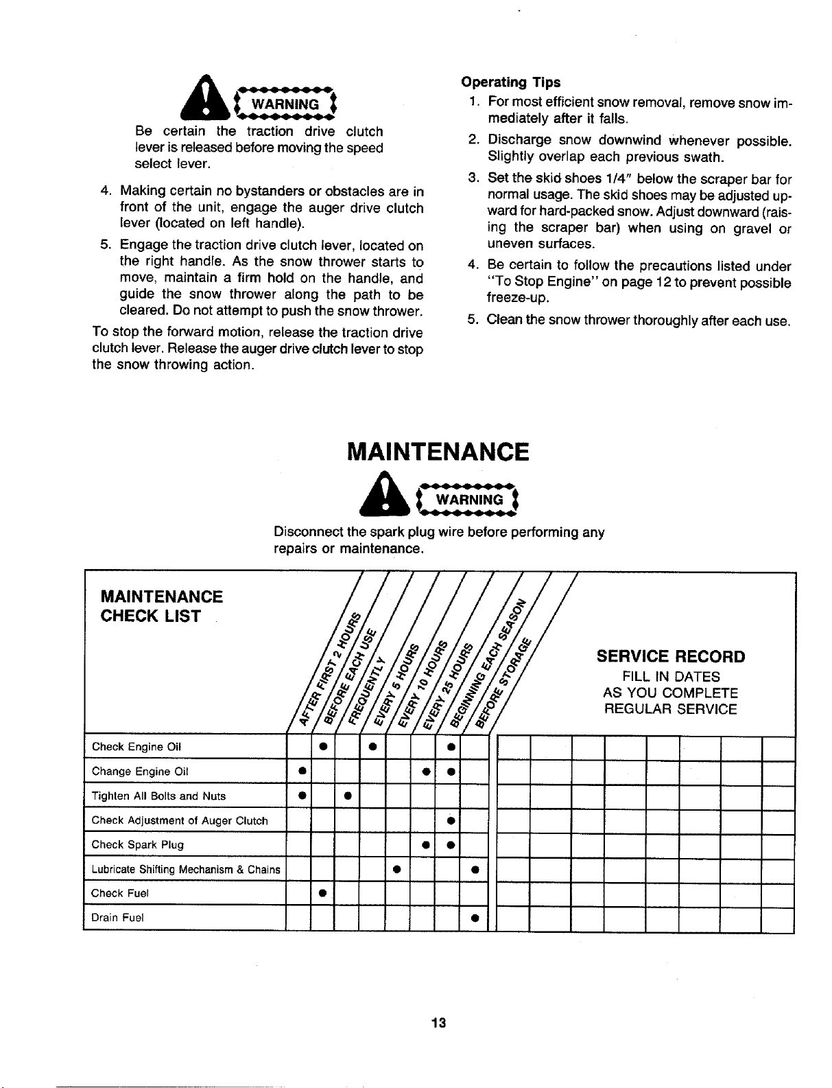
Be certain the traction drive clutch
leverisreleasedbeforemovingthespeed
selectlever.
4. Makingcertainnobystandersorobstaclesarein
frontof theunit,engagetheaugerdriveclutch
lever(locatedonlefthandle).
5. Engagethetractiondriveclutchlever,locatedon
therighthandle.Asthesnowthrowerstartsto
move,maintaina firmholdon thehandle,and
guidethe snowthroweralongthe pathto be
cleared.Donotattempttopushthesnowthrower.
Tostoptheforwardmotion,releasethetractiondrive
clutchlever.Releasetheaugerdriveclutchlevertostop
thesnowthrowingaction.
Operating Tips
I. For most efficient snow removal, remove snow im-
mediately after it falls.
2. Discharge snow downwind whenever possible.
Slightly overlap each previous swath.
3. Set the skid shoes 114" below the scraper bar for
normal usage. The skid shoes may be adjusted up-
ward for hard-packed snow. Adjust downward (rais-
ing the scraper bar) when using on gravel or
uneven surfaces.
4. Be certain to follow the precautions listed under
"To Stop Engine" on page 12 to prevent possible
freeze-up.
5. Clean the snow thrower thoroughly after each use.
MAINTENANCE
Disconnect the spark plug wire before performing any
repairs or maintenance.
Check Engine Oil • • •
SERVICE RECORD
FILL IN DATES
AS YOU COMPLETE
REGULAR SERVICE
Change Engine Oil • • •
Tighten All Bolts and Nuts • •
Check Adjustment of Auger Clutch •
Check Spark Plug • •
Lubricate Shifting Mechanism & Chains • •
Check Fuel •
Drain Fuel •
13
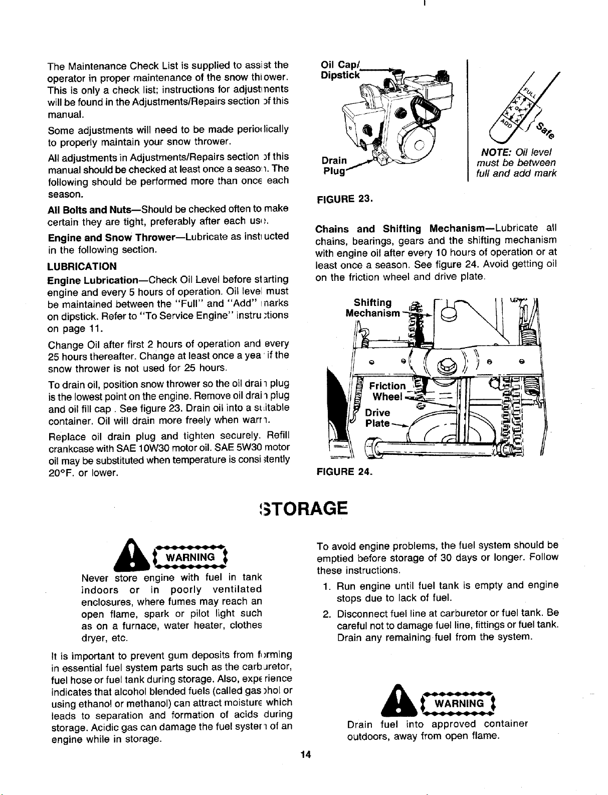
The Maintenance Check List is supplied to assist the
operator in proper maintenance of the snow thi ower.
This is only a check list; instructions for adjustments
will be found in the Adjustments/Repairs section _fthis
manual.
Some adjustments will need to be made perio{_ically
to properly maintain your snow thrower.
All adjustments in Adjustments/Repairs section _fthis
manual should be checked at least once a seaso 1.The
following should be performed more than once each
season.
All Bolts and Nuts--Should be checked often to make
certain they are tight, preferably after each us{_.
Engine and Snow Thrower--Lubricate as inst_ucted
in the following section.
LUBRICATION
Engine Lubrication--Check Oil Level before starting
engine and every 5 hours of operation. Oil level must
be maintained between the "Full" and "Add" tnarks
on dipstick. Refer to "To Service Engine" instru ;tions
on page 11.
Change Oil after first 2 hours of operation and every
25 hours thereafter. Change at least once a yea 'if the
snow thrower is not used for 25 hours.
To drain oil, position snow thrower so the oil drai 1plug
is the lowest point on the engine. Remove oil drai _ plug
and oil fill cap. See figure 23. Drain oil into a sL,itable
container. Oil will drain more freely when wart 1.
Replace oil drain plug and tighten securely. Refill
crankcase with SAE 10W30 motor oil. SAE 5W30 motor
oil may be substituted when temperature is consi ;tently
20°F. or lower.
Oil Cap/
Dips_ _
NOTE: Oi! leve/
Drain_ must be between
Plug v full and add mark
FIGURE 23.
Chains and Shifting Mechanism--Lubricate all
chains, bearings, gears and the shifting mechanism
with engine oil after every 10 hours of operation or at
least once a season. See figure 24. Avoid getting oil
on the friction wheel and drive plate.
Shifting
Friction
Drive
FIGURE 24.
GTORAGE
WARNING
....... it
Never store engine with fuel in tank
indoors or in poorly ventilated
enclosures, where fumes may reach an
open flame, spark or pilot light such
as on a furnace, water heater, clothes
dryer, etc.
It is important to prevent gum deposits from f{)rming
in essential fuel system parts such as the carburetor,
fuel hose or fuel tank during storage. Also, experience
indicates that alcohol blended fuels (called gas )hol or
using ethanol or methanol) can attract moisture which
leads to separation and formation of acids during
storage. Acidic gas can damage the fuel syster i of an
engine while in storage.
14
To avoid engine problems, the fuel system should be
emptied before storage of 30 days or longer. Follow
these instructions.
1. Run engine until fuel tank is empty and engine
stops due to lack of fuel.
2. Disconnect fuel line at carburetor or fuel tank. Be
careful not to damage fuel line, fittings or fuel tank.
Drain any remaining fuel from the system.
t WARN,NGt
Drain fuel into approved container
outdoors, away from open flame.
I_ NOTE
If gasohol has been used, complete the
preceding instructions. Then put a small
amount of unleaded (or regular) grade
gasoline into fuel tank and repeat steps
1 and 2.
3. Change oil if it has not been changed recently.
Refer to Maintenance section.
spark plug hole with a clean rag. Pull the starter
rope slowly to allow the piston to coat the internal
engine parts. Reinstall the spark plug. Do not con-
nect spark plug wire.
5. Thoroughly clean the snow thrower. If unit isto be
stored in an unventilated or metal storage shed,
coat any metal parts with a light oil or silicone to
prevent rust.
4. Remove the spark plug and squirt one ounce of
clean engine oil into spark plug hole. Cover the 6. Store in a clean, dry area.
ADJUSTMENTS/REPAIRS
WARNING_t Auger
t- _N_A-RN/I_(_-I Shear
AlwaySwSlrOPengine and disconnect spark Bolts
plug _.
before performing any
adjustments or repairs.
SKID SHOE ADJUSTMENT
The snow thrower isequipped with two adjustable skid
shoes, located on each side of the auger housing. The
skid shoes determine the distance between the scraper
bar and the ground, which varies according to the type
of surface to be cleared.
Normal, Hard Surfaces
When removing snow from a normal, hard surface such
as a paved driveway or walk, the skid shoes should be
adjusted to be approximately 1/4" lower than the
scraper bar.
To adjust, proceed as follows.
1. Make certain both tires are inflated equally (15 to
20 psi), and that neither tire is resting on a link of
the tire chains.
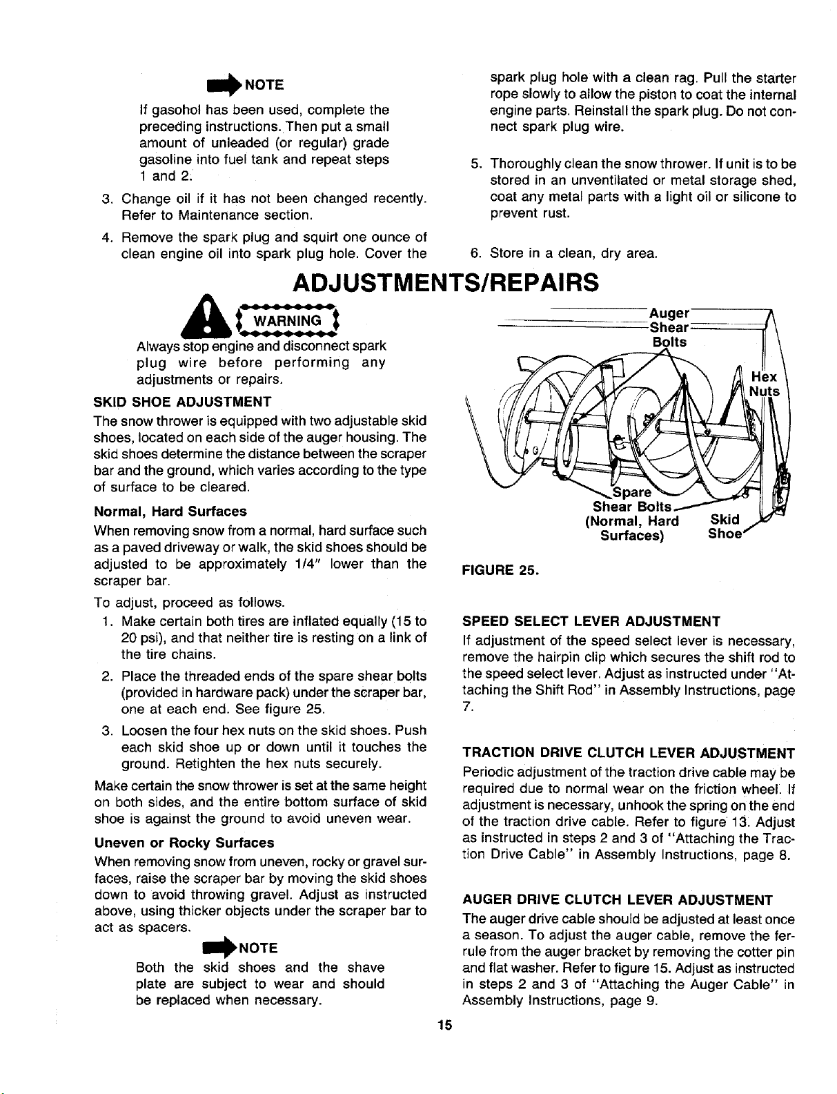
2. Place the threaded ends of the spare shear bolts
(provided in hardware pack) under the scraper bar,
one at each end. See figure 25.
3. Loosen the four hex nuts on the skid shoes. Push
each skid shoe up or down until it touches the
ground. Retighten the hex nuts securely.
Make certain the snow thrower is set at the same height
on both sides, and the entire bottom surface of skid
shoe is against the ground to avoid uneven wear.
Uneven or Rocky Surfaces
When removing snow from uneven, rockyor gravel sur-
faces, raise the scraper bar by moving the skid shoes
down to avoid throwing gravel. Adjust as instructed
above, using thicker objects under the scraper bar to
act as spacers.
IIBI_NOTE
Both the skid shoes and the shave
plate are subject to wear and should
be replaced when necessary.
FIGURE 25.
Shear Bolts/
(Normal, Hard Skid
Surfaces) Shoe"
SPEED SELECT LEVER ADJUSTMENT
If adjustment of the speed select lever is necessary,
remove the hairpin clip which secures the shift rod to
the speed select lever. Adjust as instructed under "At-
taching the Shift Rod" in Assembly Instructions, page
7.
TRACTION DRIVE CLUTCH LEVER ADJUSTMENT
Periodic adjustment of the traction drive cable may be
required due to normal wear on the friction wheel If
adjustment is necessary, unhook the spring on the end
of the traction drive cable. Refer to figure 13. Adjust
as instructed in steps 2 and 3 of "Attaching the Trac-
tion Drive Cable" in Assembly Instructions, page 8.
AUGER DRIVE CLUTCH LEVER ADJUSTMENT
The auger drive cable should be adjusted at least once
a season. To adjust the auger cable, remove the fer-
rule from the auger bracket by removing the cotter pin
and flat washer. Refer to figure 15. Adjust as instructed
in steps 2 and 3 of "Attaching the Auger Cable" in
Assembly Instructions, page 9.
15
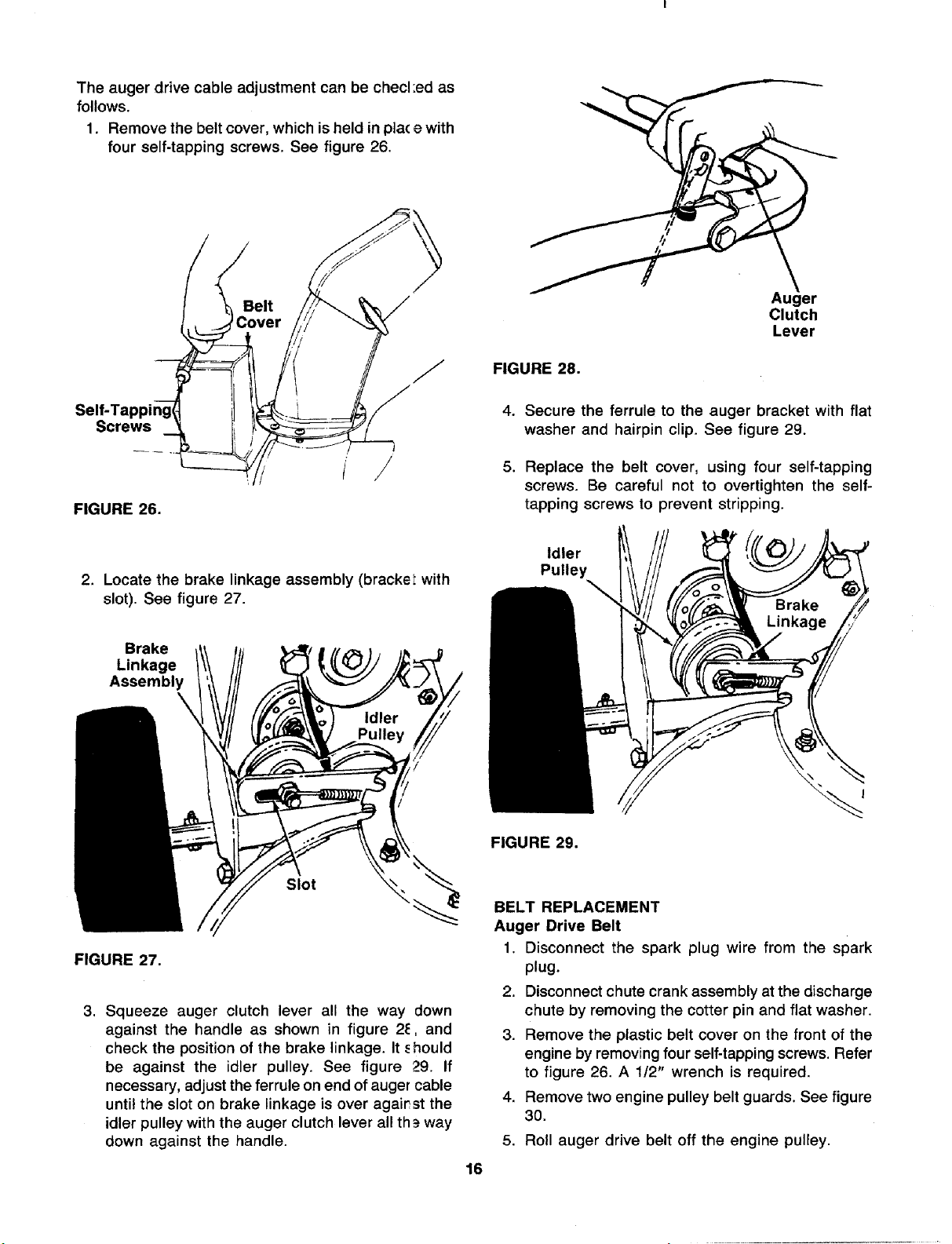
Theaugerdrivecableadjustmentcanbechecl:edas
follows.
1. Removethebeltcover,whichisheldinplacewith
fourself-tappingscrews.Seefigure26.
Screws
FIGURE 26.
Auger
Clutch
Lever
FIGURE 28.
4. Secure the ferrule to the auger bracket with flat
washer and hairpin clip. See figure 29.
5. Replace the belt cover, using four self-tapping
screws. Be careful not to overtighten the self-
tapping screws to prevent stripping.
2. Locate the brake linkage assembly (bracket with
slot). See figure 27.
Brake
Linkage
Assembly
Slot
FIGURE 27.
3. Squeeze auger clutch lever all the way down
against the handle as shown in figure 24, and
check the position of the brake linkage. It., hould
be against the idler pulley. See figure 29. If
necessary, adjust the ferrule on end of auger cable
until the slot on brake linkage is over against the
idler pulley with the auger clutch lever all th _way
down against the handle.
Idler
Pulley
FIGURE 29.
16
BELT REPLACEMENT
Auger Drive Belt
1. Disconnect the spark plug wire from the spark
plug.
2. Disconnect chute crank assembly at the discharge
chute by removing the cotter pin and flat washer.
3. Remove the plastic belt cover on the front of the
engine by removing four self-tapping screws. Refer
to figure 26. A 112" wrench is required.
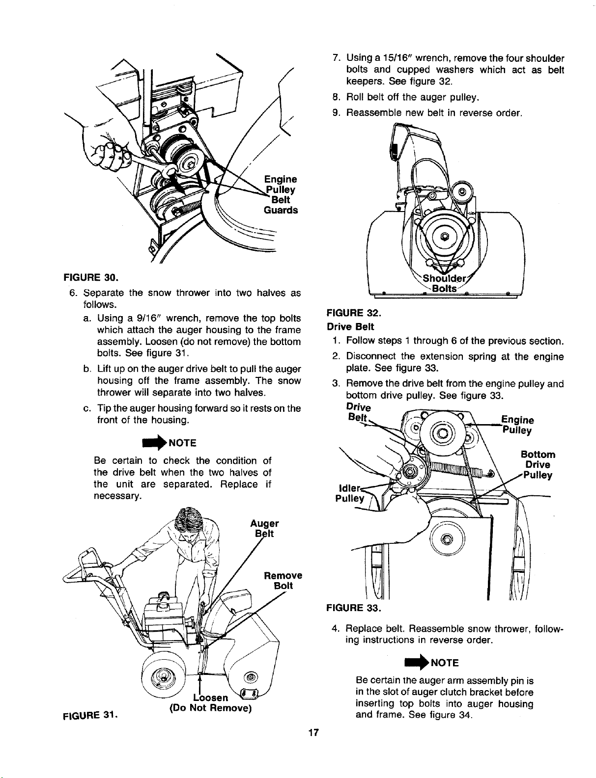
4. Remove two engine pulley belt guards. See figure
30.
5. Roll auger drive belt off the engine pulley.
\
Engine
Guards
FIGURE 30.
6. Separate the snow thrower into two halves as
follows.
a. Using a 9/16" wrench, remove the top bolts
which attach the auger housing to the frame
assembly. Loosen (do not remove) the bottom
bolts. See figure 31.
b. Lift up on the auger drive belt to pull the auger
housing off the frame assembly. The snow
thrower will separate into two halves.
c. Tip the auger housing forward so it restson the
front of the housing.
_NOTE
Be certain to check the condition of
the drive belt when the two halves of
the unit are separated. Replace if
necessary.
Auger
.*It
7. Using e 15116" wrench, remove the four shoulder
bolts and cupped washers which act as belt
keepers. See figure 32.
8. Roll belt off the auger pulley.
9. Reassemble new belt in reverse order.
I i
FIGURE 32.
Drive Belt
1. Follow steps 1 through 6 of the previous section.
2. Disconnect the extension spring at the engine
plate. See figure 33.
3. Remove the drive belt from the engine pulley and
bottom drive pulley. See figure 33.
Drive
Engine
Bottom
Drive
Pulley
FIGURE 31.
(Do Not Remove)
Remove
Bolt
[
FIGURE 33.
4. Replace belt. Reassemble snow thrower, follow-
ing instructions in reverse order.
W NOTE
Be certain the auger arm assembly pin is
in the slot of auger clutch bracket before
inserting top bolts into auger housing
and frame. See figure 34.
17
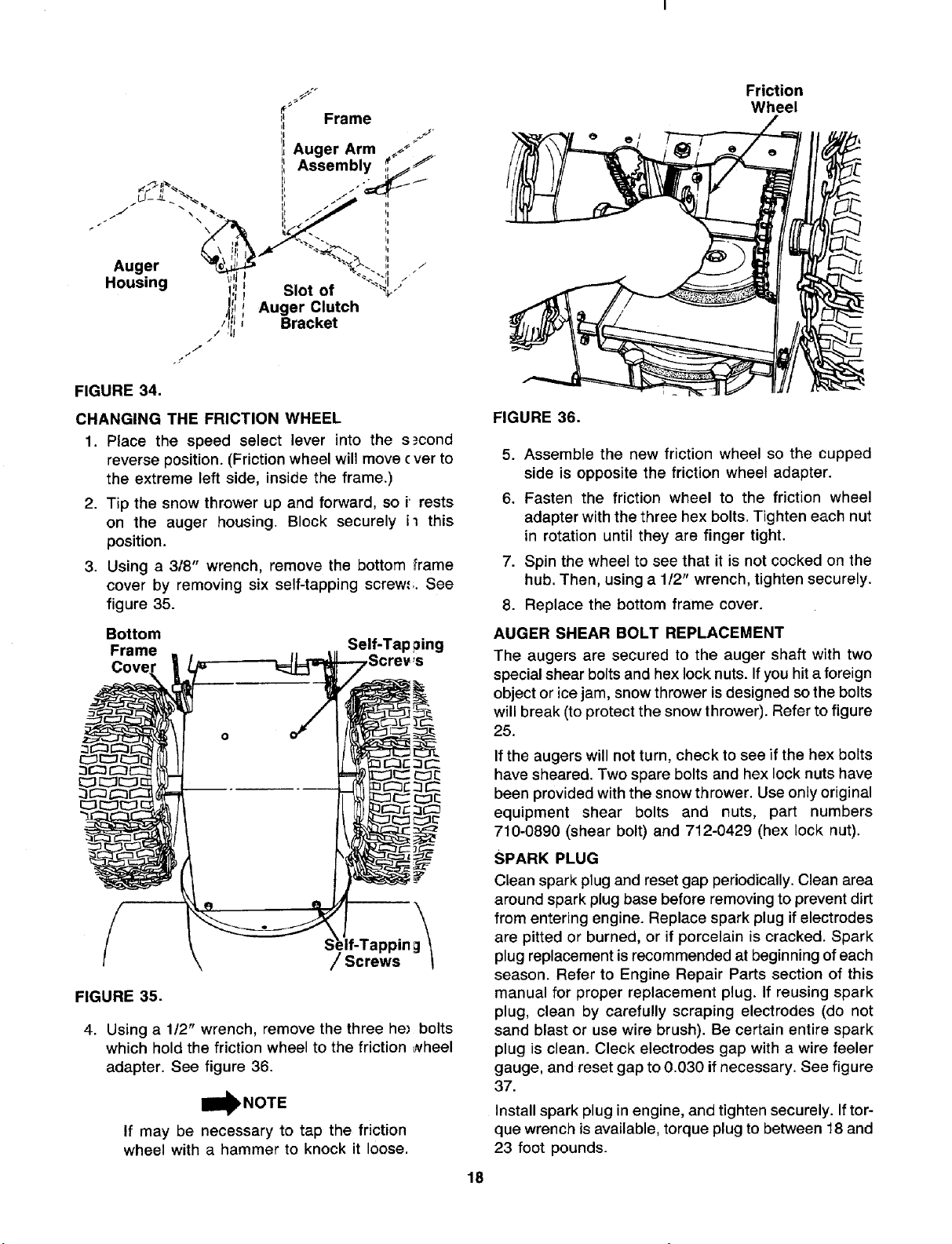
Auger
Housing ,_
'!iiJ ,oto,
Auger Clutch
./_ Bracket
7
FIGURE 34.
CHANGING THE FRICTION WHEEL
1. Place the speed select lever into the s._cond
reverse position. (Friction wheel will move ( ver to
the extreme left side, inside the frame.)
2. Tip the snow thrower up and forward, so i' rests
on the auger housing. Block securely il this
position.
3. Using a 3/8" wrench, remove the bottom frame
cover by removing six self-tapping screw.';. See
figure 35.
Bottom
Frame Self-Tap ping
Cove
4. Using a 1/2" wrench, remove the three he_ bolts
which hold the friction wheel to the friction _vheel
adapter. See figure 36.
BI_NOTE
If may be necessary to tap the friction
wheel with a hammer to knock it loose.
Friction
Wheel
18
FIGURE 36.
5. Assemble the new friction wheel so the cupped
side is opposite the friction wheel adapter.
6. Fasten the friction wheel to the friction wheel
adapter with the three hex bolts. Tighten each nut
in rotation until they are finger tight.
7. Spin the wheel to see that it is not cocked on the
hub. Then, using a 112" wrench, tighten securely.
8. Replace the bottom frame cover.
AUGER SHEAR BOLT REPLACEMENT
The augers are secured to the auger shaft with two
special shear bolts and hex lock nuts. If you hit a foreign
object or ice jam, snow thrower is designed so the bolts
will break (to protect the snow thrower). Refer to figure
25.
If the augers will not turn, check to see if the hex bolts
have sheared. Two spare bolts and hex lock nuts have
been provided with the snow thrower. Use only original
equipment shear bolts and nuts, part numbers
710-0890 (shear bolt) and 712-0429 (hex lock nut).
SPARK PLUG
Clean spark plug and reset gap periodically.Clean area
around spark plug base before removing to prevent dirt
from entering engine. Replace spark plug if electrodes
are pitted or burned, or if porcelain is cracked. Spark
plug replacement isrecommended at beginning of each
season. Refer to Engine Repair Parts section of this
manual for proper replacement plug. If reusing spark
plug, clean by carefully scraping electrodes (do not
sand blast or use wire brush). Be certain entire spark
plug is clean. Cleck electrodes gap with a wire feeler
gauge, and reset gap to 0.030 if necessary. See figure
37.
Install spark plug in engine, and tighten securely. If tor-
que wrench is available, torque plug to between 18 and
23 foot pounds.
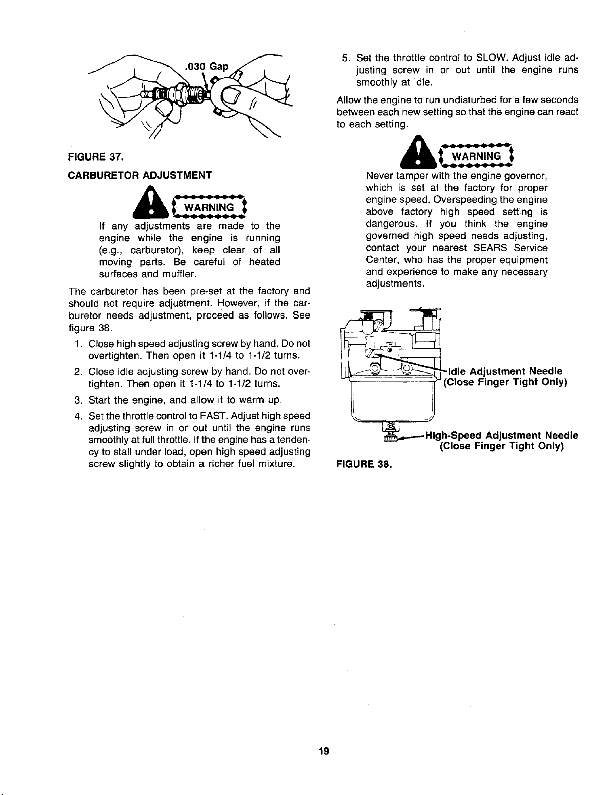
.030 Gap
FIGURE 37.
CARBURETOR ADJUSTMENT
If any adjustments are made to the
engine while the engine is running
(e.g., carburetor), keep clear of all
moving parts. Be careful of heated
surfaces and muffler.
The carburetor has been pre-set at the factory and
should not require adjustment. However, if the car-
buretor needs adjustment, proceed as follows. See
figure 38.
1. Close high speed adjusting screw by hand. Do not
overtighten. Then open it 1-1/4 to 1-1/2 turns.
2. Close idle adjusting screw by hand. Do not over-
tighten. Then open it 1-1/4 to 1-1/2 turns.
3. Start the engine, and allow it to warm up.
4. Set the throttle control to FAST. Adjust high speed
adjusting screw in or out until the engine runs
smoothly at full throttle. If the engine has a tenden-
cy to stall under load, open high speed adjusting
screw slightly to obtain a richer fuel mixture.
5. Set the throttle control to SLOW. Adjust idle ad-
justing screw in or out until the engine runs
smoothly at idle.
Allow the engine to run undisturbed for a few seconds
between each new setting so that the engine can react
to each setting.
WARNING_'_
Never tamper with the engine governor,
which is set at the factory for proper
engine speed. Overspeeding the engine
above factory high speed setting is
dangerous. If you think the engine
governed high speed needs adjusting,
contact your nearest SEARS Service
Center, who has the proper equipment
and experience to make any necessary
adjustments.
Adjustment Needle
(Close Finger Tight Only)
FIGURE 38.
Adjustment Needle
(Close Finger Tight Only)
19
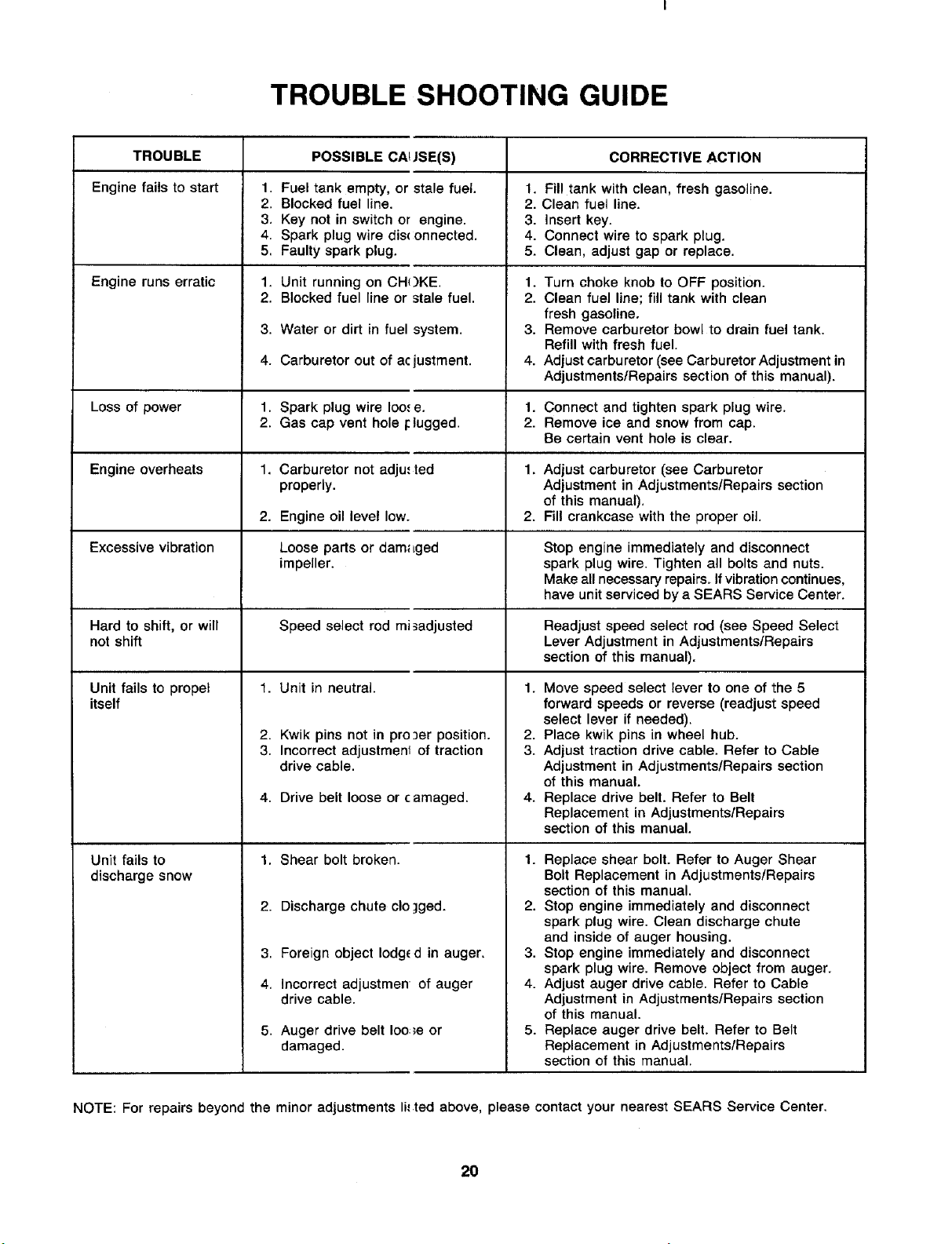
TROUBLE SHOOTING GUIDE
TROUBLE POSSIBLE CAt JSE(S) CORRECTIVE ACTION
Engine fails to start 1. Fuel tank empty, or stale fuel. 1. Fill tank with clean, fresh gasoline.
2. Blocked fuel line. 2. Clean fuel line.
3. Key not in switch or engine. 3. Insert key.
4. Spark plug wire dis_ onnected. 4. Connect wire to spark plug.
5. Faulty spark plug. 5. Clean, adjust gap or replace.
Engine runs erratic 1. Unit running on CH()KE. 1.
2. Blocked fuel line or stale fuel. 2.
Loss of power
Engine overheats
Excessive vibration
3. Water or dirt in fuel system.
4. Carburetor out of acjustment.
1. Spark plug wire Ioo,,e.
2. Gas cap vent hole IcBugged.
1. Carburetor not adju,' ted
properly.
2. Engine oil level low.
Loose parts or dam_Lged
impeller.
Turn choke knob to OFF position.
Clean fuel line; fill tank with clean
fresh gasoline.
Remove carburetor bowl to drain fuel tank.
Refill with fresh fuel.
Adjust carburetor (see Carburetor Adjustment in
Adjustments/Repairs section of this manual).
1. Connect and tighten spark plug wire.
2. Remove ice and snow from cap.
Be certain vent hole is clear.
1. Adjust carburetor (see Carburetor
Adjustment in Adjustments/Repairs section
of this manual).
2. Fill crankcase with the proper oil.
Stop engine immediately and disconnect
spark plug wire. Tighten all bolts and nuts.
Make all necessary repairs. If vibration continues,
have unit serviced by a SEARS Service Center.
Hard to shift, or will Speed select rod mi_adjusted Readjust speed select rod (see Speed Select
not shift Lever Adjustment in Adjustments/Repairs
section of this manual).
Unit fails to propel 1. Unit in neutral.
itself
2. Kwik pins not in pro ]er position.
3. Incorrect adjustmenl of traction
drive cable.
4. Drive belt loose or camaged.
Unit fails to
discharge snow
1. Shear bolt broken.
2. Discharge chute clo ]ged.
3. Foreign object lodge d in auger.
4. Incorrect adjustmen of auger
drive cable.
5. Auger drive belt Ioo,_e or
damaged.
1. Move speed select lever to one of the 5
forward speeds or reverse (readjust speed
select lever if needed).
2. Place kwik pins in wheel hub.
3. Adjust traction drive cable. Refer to Cable
Adjustment in Adjustments/Repairs section
of this manual.
4. Replace drive belt. Refer to Belt
Replacement in Adjustments/Repairs
section of this manual.
1. Replace shear bolt. Refer to Auger Shear
Bolt Replacement in Adjustments/Repairs
section of this manual.
2. Stop engine immediately and disconnect
spark plug wire. Clean discharge chute
and inside of auger housing.
3. Stop engine immediately and disconnect
spark plug wire. Remove object from auger.
4. Adjust auger drive cable. Refer to Cable
Adjustment in Adjustments/Repairs section
of this manual.
5. Replace auger drive belt. Refer to Belt
Replacement in Adjustments/Repairs
section of this manual.
NOTE: For repairs beyond the minor adjustments li,,.ted above, please contact your nearest SEARS Service Center.
20

NOTES
21
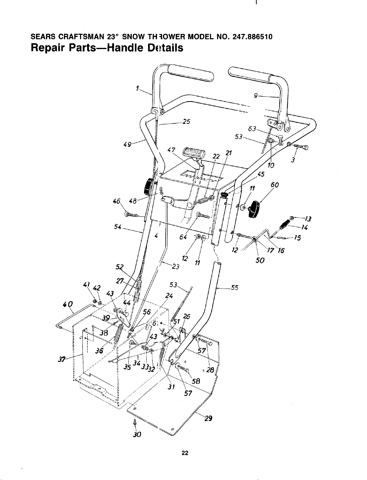
SEARS CRAFTSMAN 23" SNOW TH ::lOWER MODEL NO. 247.886510
Repair Parts--Handle D,,,tails
22 21
10
3
11 60
12
11
I
t /2
\
50
/5
60
\
If"
C
24
I
= 36..
I, i
i
7 I
f
t
+,
z
1I
I
I i
i
i
t
3O
3#
22
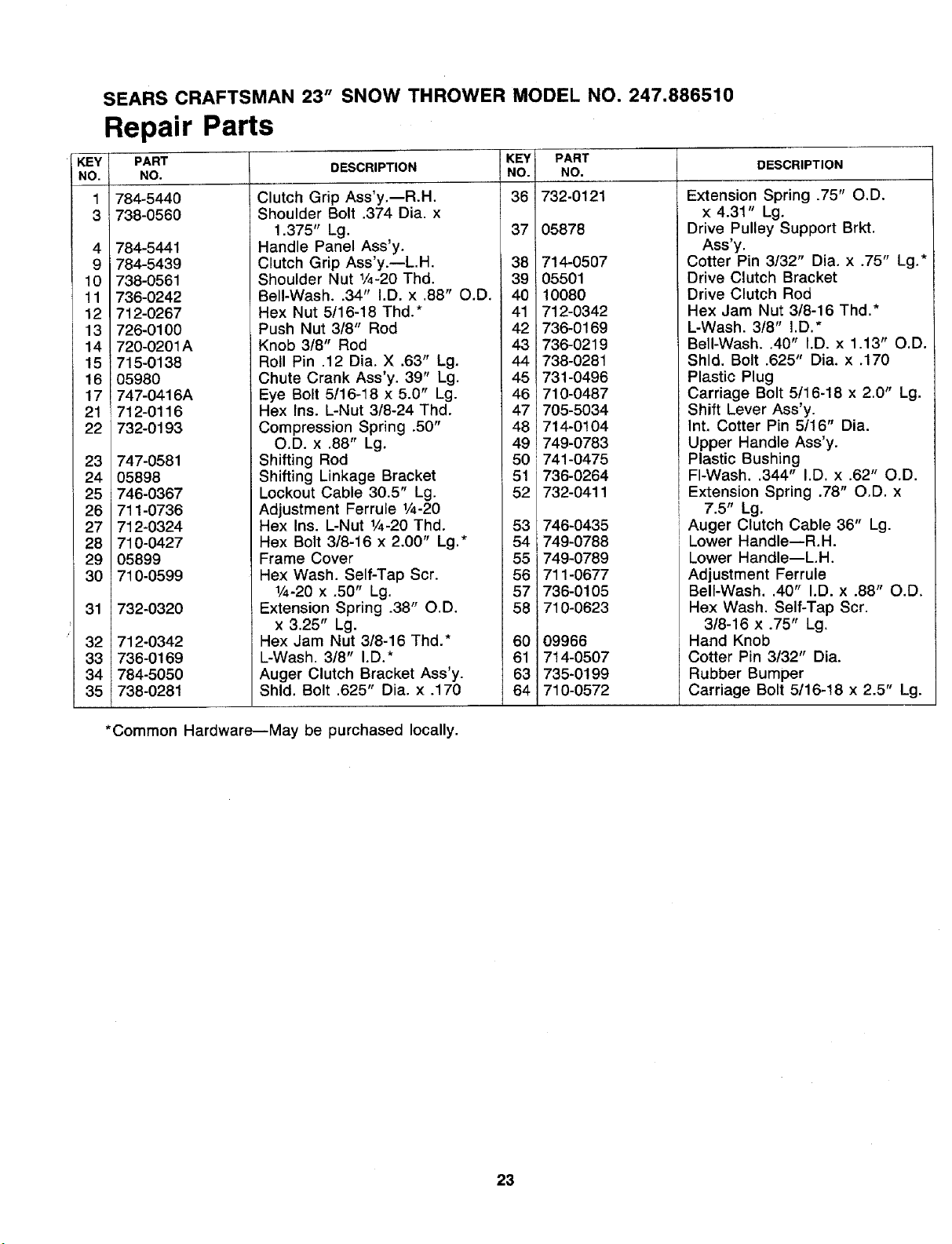
SEARS CRAFTSMAN 23" SNOW THROWER MODEL NO. 247.886510
Repair Parts
KEY
NO.
1
3
4
9
10
11
12
13
14
15
16
17
21
22
23
24
25
26
27
28
29
30
31
32
33
34
35
PART
NO.
784-5440
738-0560
784-5441
784-5439
738-0561
736-0242
712-0267
726-0100
720-0201A
715-0138
05980
747-0416A
712-0116
732-0193
747-0581
05898
746-0367
711-0736
712-0324
710-0427
05899
710-0599
732-0320
712-0342
736-0169
784-5050
738-0281
DESCRIPTION
Clutch Grip Ass'y.--R.H.
Shoulder Bolt .374 Dia. x
1.375" Lg.
Handle Panel Ass'y.
Clutch Grip Ass'y.--L.H.
Shoulder Nut 1/4-20Thd.
Bell-Wash..34" I.D. x .88" O.D.
Hex Nut 5116-18 Thd.*
Push Nut 318" Rod
Knob 3/8" Rod
Roll Pin .12 Dia. X .63" Lg.
Chute Crank Ass'y. 39" Lg.
Eye Bolt 5/16-18 x 5.0" Lg.
Hex Ins. L-Nut 318-24 Thd.
Compression Spring .50"
O.D. x .88" Lg.
Shifting Rod
Shifting Linkage Bracket
Lockout Cable 30.5" Lg.
Adjustment Ferrule 1/4-20
Hex Ins. L-Nut 1/4-20Thd.
Hex Bolt 3/8-16 x 2.00" Lg.*
Frame Cover
Hex Wash. Self-Tap Scr.
1/4-20 x .50" Lg.
Extension Spring .38" O.D.
x 3.25" Lg.
Hex Jam Nut 318-16 Thd.*
L-Wash. 3t8" I.D.*
Auger Clutch Bracket Ass'y.
Shld. Bolt .625" Dia. x .170
KEY
NO.
36
37
38
39
40
41
42
43
44
45
46
47
48
49
5O
51
52
53
54
55
56
57
58
60
61
63
64
PART
NO.
732-0121
05878
714-0507
05501
10080
712-0342
736-0169
736-0219
738-0281
731-0496
710-0487
705-5034
714-0104
749-O783
741-0475
736-0264
732-0411
746-0435
749-0788
749-0789
711-0677
736-0105
710-0623
09966
7t4-0507
735-0199
710-0572
DESCRIPTION
Extension Spring .75" O.D.
x 4.31" Lg.
Drive Pulley Support Brkt.
Ass'y.
Cotter Pin 3!32" Dia. x .75" Lg.*
Drive Clutch Bracket
Drive Clutch Rod
Hex Jam Nut 318-16 Thd.*
L-Wash. 318" I.D.*
Bell-Wash..40" I.D. x 1.13" O.D.
Shld. Bolt .625" Dia. x .170
Plastic Plug
Carriage Bolt 5116-18 x 2.0" Lg.
Shift Lever Ass'y.
Int. Cotter Pin 5/16" Dia.
Upper Handle Ass'y.
Plastic Bushing
FI-Wash..344" I.D. x .62" O.D.
Extension Spring .78" O.D. x
7.5" Lg.
Auger Clutch Cable 36" Lg.
Lower Handle--R.H.
Lower Handle--L.H.
Adjustment Ferrule
Bell-Wash..40" I.D. x .88" O.D.
Hex Wash. Self-Tap Scr.
3/8-16 x .75" Lg.
Hand Knob
Cotter Pin 3/32" Dia.
Rubber Bumper
Carriage Bolt 5/16-18 x 2.5" Lg.
*Common Hardware--May be purchased locally.
23
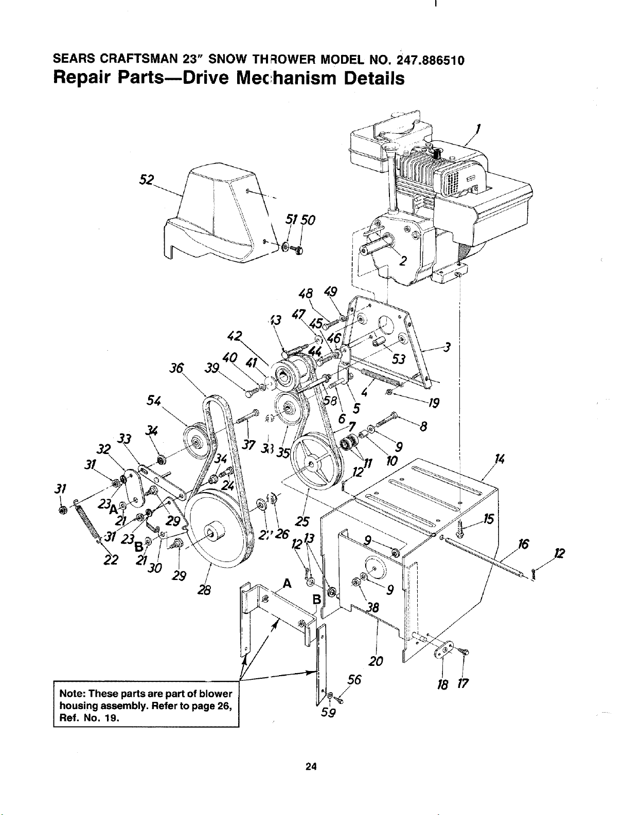
SEARS CRAFTSMAN 23" SNOW TH FLOWER MODEL NO. 247.886510
Repair Parts--Drive Mec:hanism Details
5/50
32
4
5
8
3I
29
25
A
Note: These parts are part of blower
housing assembly. Refer to page 26,
Ref. No, 19.
56
59
18 17
24
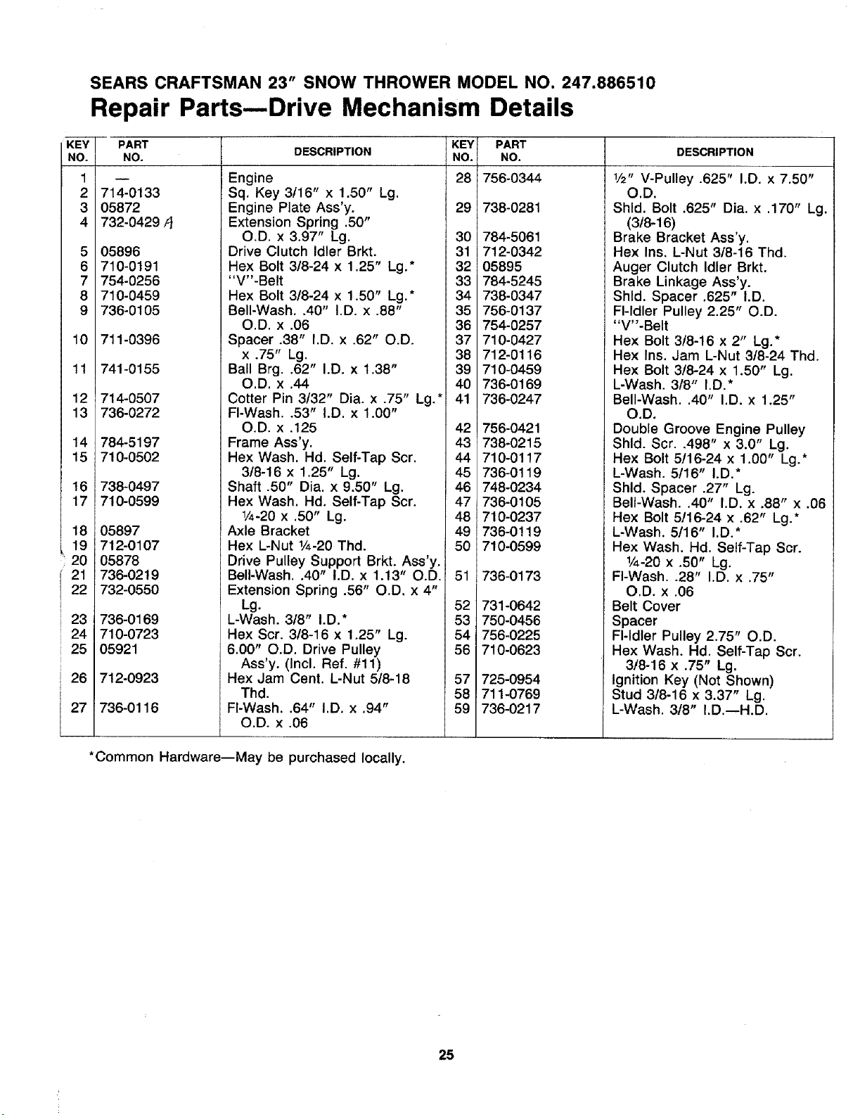
SEARS CRAFTSMAN 23" SNOW THROWER MODEL NO. 247.886510
Repair Parts--Drive Mechanism Details
KEY
NO.
1
2
3
4
5
6
7
8
9
10
11
12
13
14
15
16
17
18
19
20
21
22
23
24
25
26
27
PART
NO.
i
714-0133
05872
732-0429/I
05896
710-0191
754-0256
710-0459
736-0105
711-0396
741-0155
714-0507
736-0272
784-5197
710-0502
738-0497
710-0599
05897
712-0107
05878
736-0219
732-0550
736-0169
710-0723
05921
712-0923
736-0116
DESCRIPTION
Engine
Sq. Key 3116" x 1.50" Lg.
Engine Plate Ass'y.
Extension Spring .50"
O.D. x 3.97" Lg.
Drive Clutch Idler Brkt.
Hex Bolt 3/8-24 x 1.25" Lg.*
"V"-Belt
Hex Bolt 3/8-24 x 1.50" Lg.*
Bell-Wash..40" I.D. x .88"
O.D. x .06
Spacer 38" I.D. x .62" O.D.
x .75" Lg.
Ball Brg..62" I.D. x 1.38"
O.D. x .44
Cotter Pin 3t32" Dia. x .75" Lg.*
FI-Wash..53" I.D. x 1.00"
O.D. x .125
Frame Ass'y.
Hex Wash. Hd. Self-Tap Scr.
3/8-16 x 1.25" Lg.
Shaft .50" Dia. x 9.50" Lg.
Hex Wash. Hd. Self-Tap Scr.
1/4-20x .50" Lg.
Axle Bracket
Hex L-Nut 1/4-20Thd.
Drive Pulley Support Brkt. Ass'y.
Bell-Wash..40" I.D. x 1.13" O.D,
Extension Spring .56" O.D. x 4"
Lg.
L-Wash. 3/8" I.D.*
Hex Scr. 3/8-16 x 1.25" Lg.
6.00" O.D. Drive Pulley
Ass'y. (Incl. Ref, #11)
Hex Jam Cent. L-Nut 5/8-18
Thd.
FI-Wash..64" I.D. x .94"
O.D. x .06
KEY
NO.
28
29
3O
31
32
33
34
35
36
37
38
39
40
41
42
43
44
45
46
47
48
49
5O
51
52
53
54
56
57
58
59
PART
NO.
756-0344
738-0281
784-5061
712-0342
05895
784-5245
738-0347
756-0137
754-0257
710-0427
712-0116
710-0459
736-0169
736-0247
756-0421
738-0215
710-0117
736-0119
748-0234
736-0105
710-0237
736-0119
710-0599
736-0173
731-0642
750-0456
756-0225
710-0623
725-0954
_711-0769
736-0217
DESCRIPTION
1/2" V-Pulley .625" I.D. x 7.50"
O.D.
Shld. Bolt 325" Dia. x .170" Lg.
(3/8-16)
Brake Bracket Ass'y.
Hex Ins. L-Nut 3/8-16 Thd.
Auger Clutch Idler Brkt.
Brake Linkage Ass'y.
Shld. Spacer .625" I.D.
Fl-ldler Pulley 2.25" O.D.
"V"-Belt
Hex Bolt 3t8-16 x 2" Lg.*
Hex Ins. Jam L-Nut 3/8-24 Thd.
Hex Bolt 3/8-24 x 1.50" Lg.
L-Wash. 3/8" I.D.*
Bell-Wash..40" I.D. x 1.25"
O.D.
Double Groove Engine Pulley
Shld. Scr..498" x 3.0" Lg.
Hex Bolt 5/16-24 x 1.00" Lg.*
L-Wash. 5/16" I.D.*
Shld. Spacer .27" Lg.
Bell-Wash..40" I.D. x .88" x .06
Hex Bolt 5!16-24 x .62" Lg.*
L-Wash. 5/16" I.D.*
Hex Wash. Hd. Self-Tap Scr.
1/4-20 x .50" Lg.
FI-Wash..28" I.D. x .75"
O.D. x .06
Belt Cover
Spacer
Fl-ldler Pulley 2.75" O.D.
Hex Wash. Hd. Self-Tap Scr.
3/8-16 x .75" Lg.
Ignition Key (Not Shown)
Stud 3/8-16 x 3.37" Lg.
L-Wash. 318" I.D.--H.D.
*Common Hardware--May be purchased locally.
25
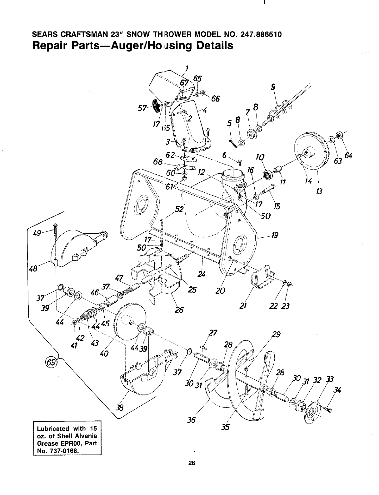
SEARS CRAFTSMAN 23 = SNOW TH;::IOWER MODEL NO. 247.886510
Repair Parts--Auger/Ho_Jsing Details
I
65
11
14 l
;8
I
I
I
Lubricated with 15
oz. of Shell Alvania
Grease EPR0O, Part
No. 737-0168.
25 2O
27
3?
/
3O
/
36
35
21
2223
29
/
/
28
/
33
34
/
26
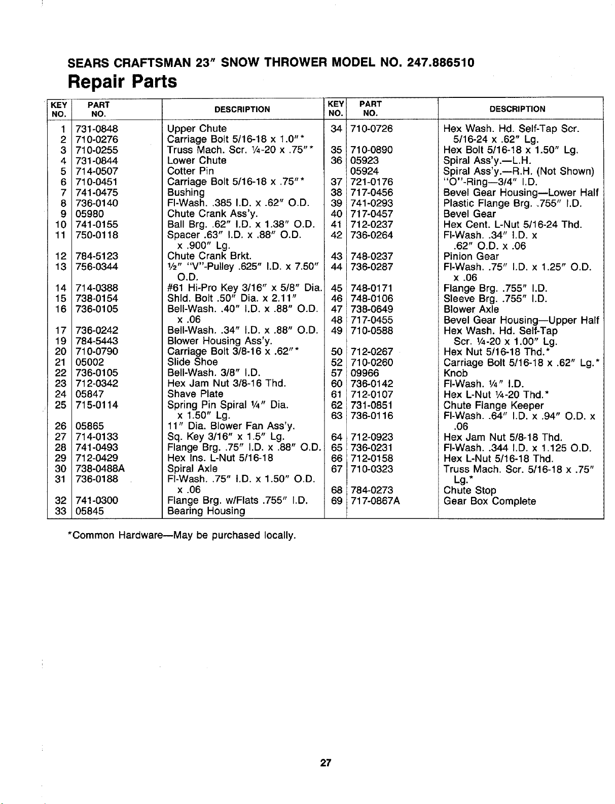
SEARS CRAFTSMAN 23" SNOW THROWER MODEL NO. 247.886510
Repair Parts
KEY
NO,
1
2
3
4
5
6
7
8
9
10
11
12
13
14
15
16
17
19
20
21
22
23
24
25
26
27
28
29
30
31
32
33
PART
NO.
731-0848
710-0276
710-0255
731-0844
714-0507
710-0451
741-0475
736-0140
05980
741-0155
750-0118
784-5123
756-0344
714-0388
738-0154
736-0105
736-0242
784-5443
710-0790
05002
736-0105
712-0342
05847
715-0114
05865
714-0133
741-0493
712-0429
738-0488A
736-0188
741-0300
05845
DESCRIPTION
Upper Chute
Carriage Bolt 5/16-18 x 1.0"*
Truss Mach, Scr, 1/4-20x .75"* 35
Lower Chute 36
Cotter Pin
Carriage Bolt 5/16-18 x .75"* 37
Bushing 38
FI-Wash..385 I.D. x .62" O.D. 39
Chute Crank Ass'y. 40
Ball Brg, .62" I.D. x 1.38" O.D. 41
Spacer .63" I.D. x .88" O.D. 42
x .900" Lg.
Chute Crank Brkt. 43
1/2.... V"-Pulley .625" I,D. x 7.50" 44
O.D.
#61 Hi-Pro Key 3/16" x 5/8" Dia. 45
Shld. Bolt .50" Dia. x 2.11" 46
Bell-Wash, .40" I.D. x .88" O.D. 47
x .06 48
Bell-Wash..34" I.D. x .88" O.D. 49
Blower Housing Ass'y.
Carriage Bolt 3/8-16 x .62"* 50
Slide Shoe 52
Bell-Wash. 3!8" I.D. 57
Hex Jam Nut 3/8-16 Thd. 60
Shave Plate 61
Spring Pin Spiral 1/4" Dia. 62
x 1.50" Lg. 63
11" Dia. Blower Fan Ass'y.
Sq. Key 3t16" x 1.5" Lg. 64
Flange Brg..75" I.D. x .88" O.D. 65
Hex Ins. L-Nut 5/16-18 66
Spiral Axle 67
FI-Wash..75" I.D. x 1.50" O.D.
x .06 68
Flange Brg. w/Flats .755" I,D. 69
Bearing Housing
KEY PART
NO. NO.
34 710-0726
710-0890
05923
05924
721-0176
717-0456
741-0293
717-0457
712-0237
736-0264
748-0237
736-0287
748-0171
748-0106
738-0649
717-0455
710-0588
712-0267
710-0260
09966
736-0142
712-0107
731-0851
736-0116
712-0923
736-0231
712-0158
710-0323
784-0273
717-0867A
DESCRIPTION
Hex Wash. Hd. Self-Tap Scr.
5/16-24 x .62" Lg.
Hex Bolt 5/16-18 x 1.50" Lg.
Spiral Ass'y.--L.H.
Spiral Ass'y.--R.H. (Not Shown)
"O"-Ring--3t4" I.D.
Bevel Gear Housing--Lower Half
Plastic Flange Brg..755" I.D.
Bevel Gear
Hex Cent. L-Nut 5/16-24 Thd.
FI-Wash..34" I.D. x
.62" O.D. x .06
Pinion Gear
FI-Wash..75" I.D. x 1.25" O.D.
x .06
Flange Brg..755" I.D.
Sleeve Brg..755" I.D.
Blower Axle
Bevel Gear Housing--Upper Half
Hex Wash. Hd. Self-Tap
Scr. 1/4-20x 1.00" Lg.
Hex Nut 5/16-18 Thd.*
Carriage Bolt 5/16-18 x .62" Lg.*
Knob
Fl-Wash. 1/4" I.D.
Hex L-Nut 1/4-20 Thd.*
Chute Flange Keeper
FI-Wash..64" I.D. x .94" O.D. x
.06
Hex Jam Nut 5/8-18 Thd.
FI-Wash..344 I.D. x 1.125 O.D.
Hex L-Nut 5/16-18 Thd.
Truss Mach. Scr. 5/16-18 x .75"
Lg.*
Chute Stop
Gear Box Complete
*Common Hardware--May be purchased locally.
27
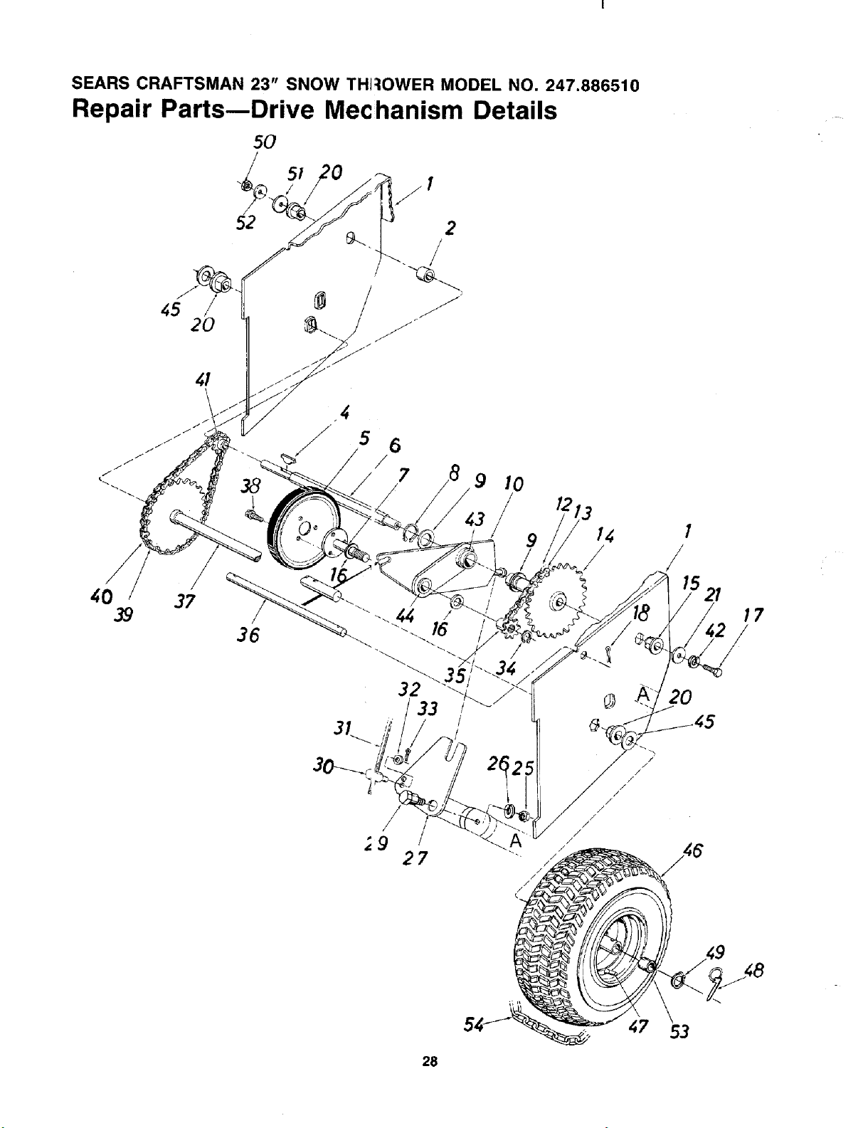
SEARS CRAFTSMAN 23" SNOW THF:IOWER MODEL NO. 247.886510
Repair Parts--Drive Mechanism Details
5O
51 I
2O
2
/
37
38
4
32
!
_9 /
27
10
/
14
/
/'
/
/
/
/
/
/
/
/
/
/
/
1
/
20
17
28
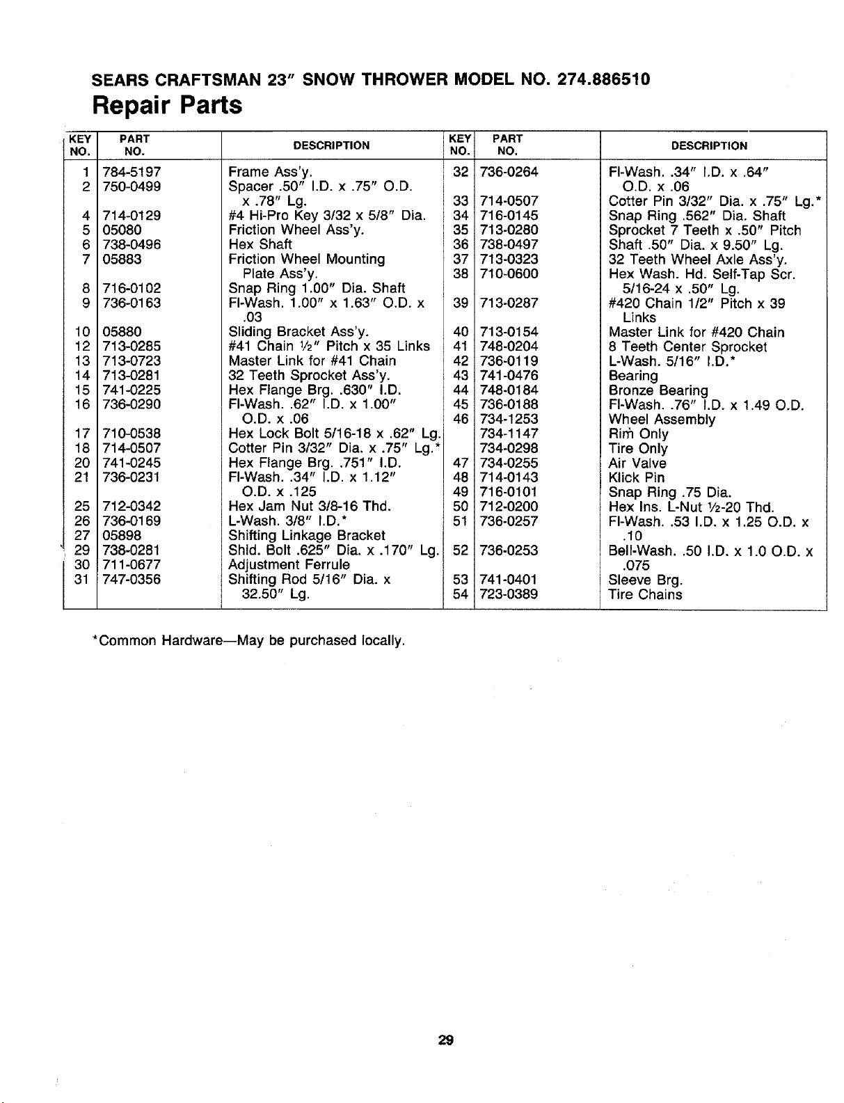
SEARS CRAFTSMAN 23" SNOW THROWER MODEL NO. 274.886510
Repair Parts
KEY
NO.
1
2
4
5
6
7
8
9
10
12
13
14
15
16
17
18
20
21
25
26
27
29
30
31
PART
NO.
784-5197
750-0499
714-0129
05080
738-0496
05883
716-0102
736-0163
05880
713-0285
713-0723
713-0281
741-0225
736-0290
710-0538
714-0507
741-0245
736-0231
712-0342
736-0169
05898
738-0281
711-0677
747-0356
DESCRIPTION
KEY
NO.
32
Frame Ass'y.
Spacer .50" I.D. x .75" O.D.
x .78" Lg. 33
#4 Hi-Pro Key 3t32 x 5/8" Dia. 34
Friction Wheel Ass'y. 35
Hex Shaft 36
Friction Wheel Mounting 37
Plate Ass'y. 38
Snap Ring 1.00" Dia. Shaft
FI-Wash. 1.00" x 1.63" O.D. x 39
PART
NO.
736-0264
714-0507
716-0145
713-0280
738-0497
713-0323
710-0600
713-0287
DESCRIPTION
FI-Wash..34" I.D. x .64"
O.D. x .06
Cotter Pin 3/32" Dia. x .75" Lg.*
Snap Ring .562" Dia. Shaft
Sprocket 7 Teeth x .50" Pitch
Shaft .50" Dia. x 9.50" Lg.
32 Teeth Wheel Axle Ass'y.
Hex Wash. Hd. Self-Tap Scr.
5/16-24 x .50" Lg.
#420 Chain 1/2" Pitch x 39
.O3
Sliding Bracket Ass'y.
#41 Chain 1/2" Pitch x 35 Links
Master Link for #41 Chain
32 Teeth Sprocket Ass'y.
Hex Flange Brg..630" I.D.
FI-Wash..62" I.D. x 1.00"
O.D. x .06
Hex Lock Bolt 5/16-18 x .62" Lg.
Cotter Pin 3/32" Dia. x .75" Lg.*
Hex Flange Brg..751" I.D.
40 713-0154
41 748-0204
42 736-0119
43 741-0476
44 748-0184
45 736-0188
46
47
734-1253
734-1147
734-0298
734-0255
Links
Master Link for #420 Chain
8 Teeth Center Sprocket
L-Wash. 5/16" I.D.*
Bearing
Bronze Bearing
FI-Wash..76" I.D. x 1.49 O.D.
Wheel Assembly
Rirfi Only
Tire Only
Air Valve
FI-Wash..34" I.D. x 1.12"
O.D. x .125
Hex Jam Nut 3/8-16 Thd.
L-Wash. 318" I.D.*
Shifting Linkage Bracket
Shld. Bolt .625" Dia. x .170" Lg.
Adjustment Ferrule
Shifting Rod 5/16" Dia. x
32.50" Lg.
48 714-0143
49 716-0101
50 712-0200
51 736-0257
52 736-0253
53
54
741-0401
723-0369
Klick Pin
Snap Ring .75 Dia.
Hex Ins. L-Nut 1/2-20 Thd.
FI-Wash..53 I.D. x 1.25 O.D. x
.10
Bell.Wash..50 I.D. x 1.00.D. x
.075
Sleeve Brg.
Tire Chains
*Common Hardware--May be purchased locally.
29
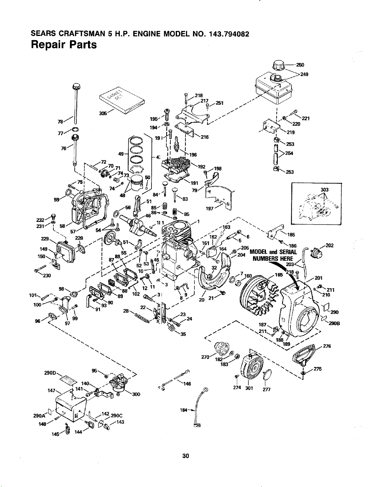
SEARS CRAFTSMAN 5 H.P. ENGINE MODEL NO. 143.794082
Repair Parts
nJ _
L..
232J_
231J _.
229
,218
3O3
91
>
3O
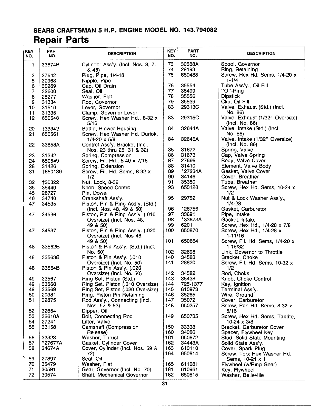
SEARS CRAFTSMAN 5 H.P, ENGINE MODEL NO. 143.794082
Repair Parts
KEY
NO.
3
5
6
7
8
9
10
11
12
20
21
22
23
24
28
31
32
35
45
46
47
47
47
48
48
48
49
49
49
5O
51
52
53
54
55
56
57
58
59
70
71
72
PART
NO.
33674B
27642
30968
30969
32600
28277
31334
31510
31335
650548
t33342
650561
33858A
31342
650549
31426
t650139
t30322
35440
26727
34740
34535
34536
34537
33562B
33563B
33564B
33567
33568
33569
20381
32875
32654
32610A
27241
33158
32323
"27677A
34674A
27897
35479
30591
30574
DESCRIPTION
Cylinder Ass'y. (Incl. Nos. 3, 7,
& 45)
Plug, Pipe, 1/4-18
Nipple, Pipe
Cap, Oil Drain
Seal, Oil
Washer, Flat
Rod, Governor
Lever, Governor
Clamp, Governor Lever
Screw, Hex Washer Hd., 8-32 x
5/16
Baffle, Blower Housing
Screw, Hex Washer Hd. Durlok,
1t4-20 x 5/8
Control Ass'y. Bracket (Incl.
Nos. 23 thru 25, 31 & 32)
Spring, Compression
Screw, Fil. Hd., 5-40 x 7!16
Spring, Extension
Screw, Fil. Hd. Sems, 8-32 x
1/2
Nut, Lock, 8-32
Knob, Speed Control
Pin, Dowel
Crankshaft Ass'y.
Piston, Pin & Ring Ass'y. (Std.)
(Incl. Nos. 48, 49 & 50)
Piston, Pin & Ring Ass'y. (.010
Oversize) (Incl. Nos. 48,
49 & 50)
Piston, Pin & Ring Ass'y. (.020
Oversize) (Incl. Nos 48,
49 & 50)
Piston & Pin Ass'y. (Std.) (Incl.
No. 50)
Piston & Pin Ass'y. (.010
Oversize) (Incl. No. 50)
Piston & Pin Ass'y. (.020
Oversize) (Incl. No. 50)
Ring Set, Piston (Std.)
Ring Set, Piston (.010 Oversize)
Ring Set, Piston (.020 Oversize)
Ring, Piston Pin Retaining
Rod Ass'y., Connecting (Incl.
Nos. 52 & 53)
Dipper, Oil
Bolt, Connecting Rod
Lifter, Valve
Camshaft (Compression
Release)
Washer, Thrust
Gasket, Cylinder Cover
Cover, Cylinder (Incl. Nos. 59 &
72)
Seal, Oil
Washer, Flat
Gear, Governor (Incl. No. 70)
Shaft, Mechanical Governor
KEY PART
NO. NO.
73 30588A
74 29193
75 650488
76 35554
77 35499
78 35556
79 35539
83 29313C
83 29315C
84 32644A
84 32645A
85 31672
86 31673
87 27666
88 31410
89 "27234A
90 34146
91 35350
93 650128
95 29752
96 *26756
97 33691
98 "33673A
99 6201
100 650870
101 650664
102 32698
140 34583
141 28820
142 34582
143 35438
144 725-1377
145 610973
146 35285
147 35072
148 650257
149 650735
150 33333
160 34080
161 650872
162 34443A
163 610118
164 650814
165 611081
181 610961
182 650815
DESCRIPTION
Spool, Governor
Ring, Retaining
Screw, Hex Hd. Sems, 1/4-20 x
1-1/4
Tube Ass'y, Oil Fill
"O"-Ring
Dipstick
Clip, Oil Fill
Valve, Exhaust (Std.) (Incl.
No. 86)
Valve, Exhaust (1/32" Oversize)
(Incl. No. 86)
Valve, Intake (Std.) (Incl.
No. 86)
Valve, Intake (1t32" Oversize)
(Incl. No. 86)
Spring, Valve
Cap, Valve Spring
Body, Valve Cover
Element, Valve Body
Gasket, Valve Cover
Cover, Breather
Tube, Breather
Screw, Hex Hd. Sems, 10-24 x
1/2
Nut & Lock Washer Ass'y.,
1/4-28
Gasket, Carburetor
Pipe, Intake
Gasket, Intake
Screw, Hex Hd., 1/4-28 x 7/8
Screw, Hex Hd., 1/4-28 x
1-11/16
Screw, Fil. Hd. Sems, 1/4-20 x
1-19132
Link, Governor to Throttle
Bracket, Choke
Screw, Fil. Hd. Seres, 10-32 x
1/2
Rod, Choke
Knob, Choke Control
Key, Ignition
Terminal Ass'y.
Wire, Ground
Cover, Carburetor
Screw, Pan Hd. Sems, 8-32 x
5/16
Screw, Hex Hd. Sems, Taptite,
10-24 x 3/8
Bracket, Carburetor Cover
Spacer, Flywheel Key
Stud, Solid State Mounting
Solid State Ass'y.
Cover, Spark Plug
Screw, Torx Hex Washer Hd.
Sems, 10-24 x 1
Flywheel (wiRing Gear)
Key, Flywheel
Washer, Belleville
31
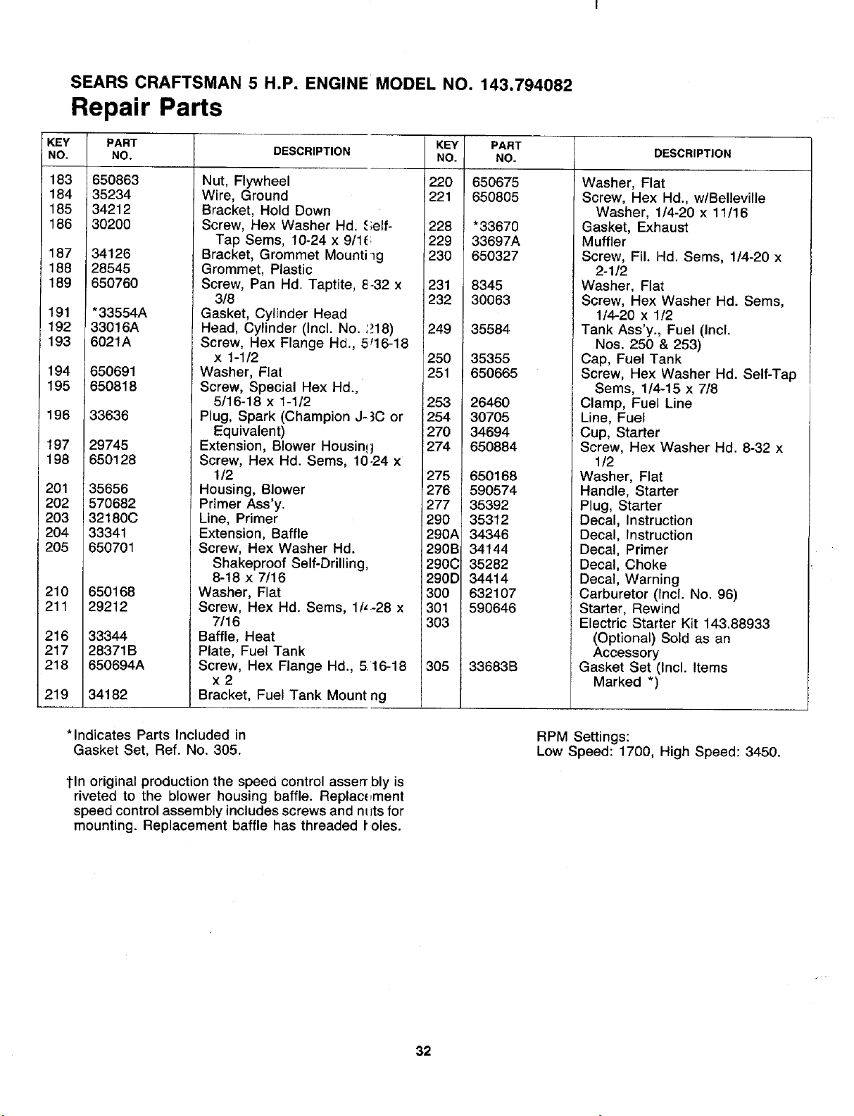
SEARS CRAFTSMAN 5 H.P. ENGINE MODEL NO. 143.794082
Repair Parts
KEY
NO.
183
184
185
186
187
188
189
191
192
193
194
195
196
197
198
201
202
203
204
205
210
211
216
217
218
219
PART
NO.
650863
35234
34212
30200
34126
28545
650760
"33554A
33016A
6021A
650691
650818
33636
29745
650128
35656
570682
32180C
33341
6507O1
650168
29212
33344
28371B
650694A
34182
DESCRIPTION KEY
NO.
Nut, Flywheel
Wire, Ground
Bracket, Hold Down
Screw, Hex Washer Hd. elf-
Tap Sems, 10-24 x 9/11
Bracket, Grommet Mounti _g
Grommet, Plastic
Screw, Pan Hd. Taptite, _ 32 x
3/8
Gasket, Cylinder Head
Head, Cylinder (Incl. No. :18)
Screw, Hex Flange Hd., _ 16-18
x 1-1/2
Washer, Flat
Screw, Special Hex Hd.,
5/16-18 x 1-112
Plug, Spark (Champion J- _Cor
Equivalent)
Extension, Blower Housin,
Screw, Hex Hd. Seres, 1(_24 x
1/2
Housing, Blower
Primer Ass'y.
Line, Primer
Extension, Baffle
Screw, Hex Washer Hd.
Shakeproof Self-Drilling
8-18 x 7t16
Washer, Flat
Screw, Hex Hd. Sems, 11,.28 x
7/16
Baffle, Heat
Plate, Fuel Tank
Screw, Hex Flange Hd., 5 16-18
x2
Bracket, Fuel Tank Mount _g
1220
i221
228
229
230
231
232
249
25O
251
253
254
270
274
275
276
277
290
290A
290B
290C
290D
300
301
1303
305
PART
NO.
650675
650805
*33670
33697A
650327
8345
30063
35584
35355
650665
26460
30705
34694
650884
650168
590574
35392
35312
34346
34144
35282
34414
632107
590646
33683B
DESCRIPTION
Washer, Flat
Screw, Hex Hd., wlBelleville
Washer, 1/4-20 x 11t16
Gasket, Exhaust
Muffler
Screw, Fil. Hd. Sems, 1/4-20 x
2-1/2
Washer, Flat
Screw, Hex Washer Hd. Sems,
1/4-20 x 1/2
Tank Ass'y., Fuel (Incl.
Nos. 250 & 253)
Cap, Fuel Tank
Screw, Hex Washer Hd. Self-Tap
Sems, 1/4-15 x 7/8
Clamp, Fuel Line
Line, Fuel
Cup, Starter
Screw, Hex Washer Hd. 8-32 x
1t2
Washer, Flat
Handle, Starter
Plug, Starter
Decal, Instruction
Decal, Instruction
Decal, Primer
Decal, Choke
Decal, Warning
Carburetor (Incl. No. 96)
Starter, Rewind
Electric Starter Kit 143.88933
(Optional) Sold as an
Accessory
Gasket Set (Incl. Items
Marked *)
*Indicates Parts Included in
Gasket Set, Ref. No. 305.
tin original production the speed control asserTbly is
riveted to the blower housing baffle. Replac_iment
speed control assembly includes screws and mits for
mounting. Replacement baffle has threaded roles.
RPM Settings:
Low Speed: 1700, High Speed: 3450.
32
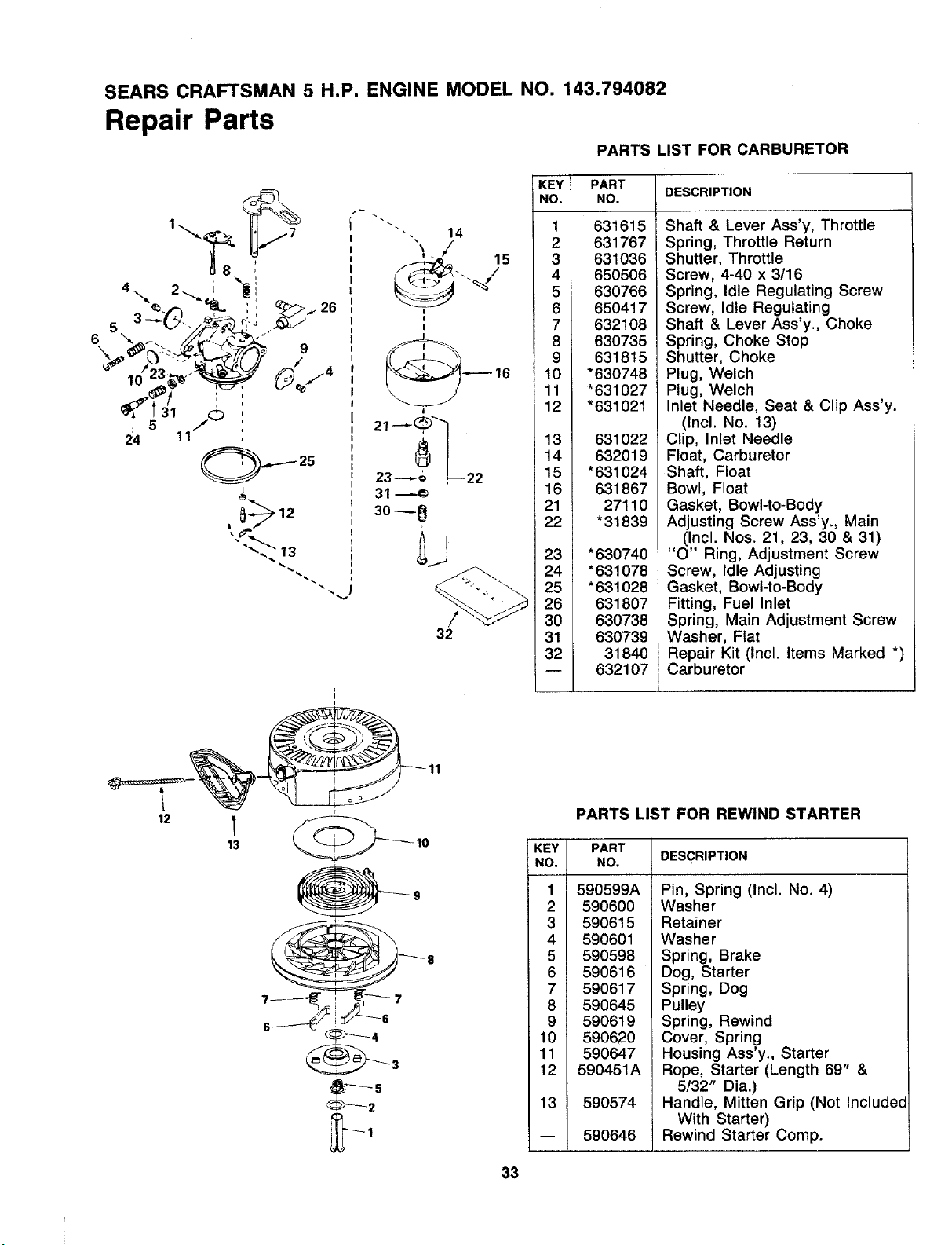
SEARS CRAFTSMAN 5 H.P. ENGINE MODEL NO. 143.794082
Repair Parts
PARTS LIST FOR CARBURETOR
32
i
I
13 _ 10
_2
KEY PART
NO. NO. DESCRIPTION
1 631615
2 631767
3 631036
4 650506
5 630766
6 650417
7 632108
8 630735
9 631815
10 *630748
11 *631027
12 *631021
13 631022
14 632019
15 *631024
16 631867
21 27110
22 *31839
23 *630740
24 "631078
25 *631028
26 631807
30 630738
31 630739
32 31840
-- 632107
Shaft & Lever Ass'y, Throttle
Spring, Throttle Return
Shutter, Throttle
Screw, 4-40 x 3/16
Spring, Idle Regulating Screw
Screw, Idle Regulating
Shaft & Lever Ass'y., Choke
Spring, Choke Stop
Shutter, Choke
Plug, Welch
Plug, Welch
Inlet Needle, Seat & Clip Ass'y.
(Incl. No. 13)
Clip, Inlet Needle
Float, Carburetor
Shaft, Float
Bowl, Float
Gasket, Bowl-to-Body
Adjusting Screw Ass'y., Main
(Incl. Nos. 21, 23, 30 & 31)
"O" Ring, Adjustment Screw
Screw, Idle Adjusting
Gasket, Bowl-to-Body
Fitting, Fuel Inlet
Spring, Main Adjustment Screw
Washer, Flat
Repair Kit (Incl. Items Marked *)
Carburetor
PARTS LIST FOR REWIND STARTER
KEY
NO.
1 590599A
2 590600
3 590615
4 590601
5 590598
6 590616
7 590617
8 590645
9 590619
10 590620
11 590647
12 590451A
13 590574
PART
NO. DESCRIPTION
590646
Pin, Spring (Incl. No. 4)
Washer
Retainer
Washer
Spring, Brake
Dog, Starter
Spring, Dog
Pulley
Spring, Rewind
Cover, Spring
Housing Ass'y., Starter
Rope, Starter (Length 69" &
5132" Dia.)
Handle, Mitten Grip (Not Included
With Starter)
Rewind Starter Comp.
33
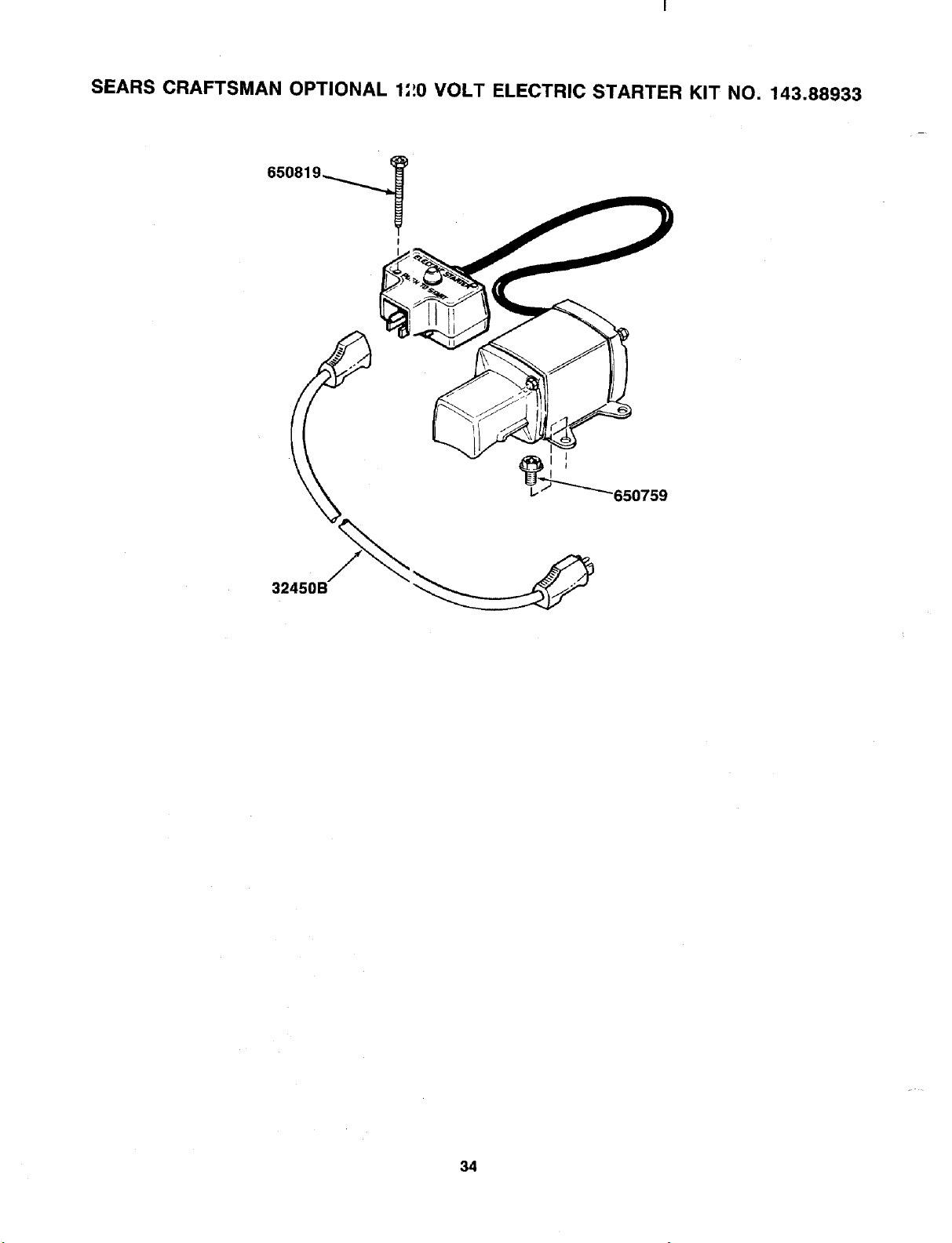
SEARS CRAFTSMAN OPTIONAL 1',_0 VOLT ELECTRIC STARTER KIT NO, 143.88933
650819_
I
32450B
34

owner's
manual
MODEL NO.
247.886510
SEARS
SERVICE
is at
YOUR
SERVICE
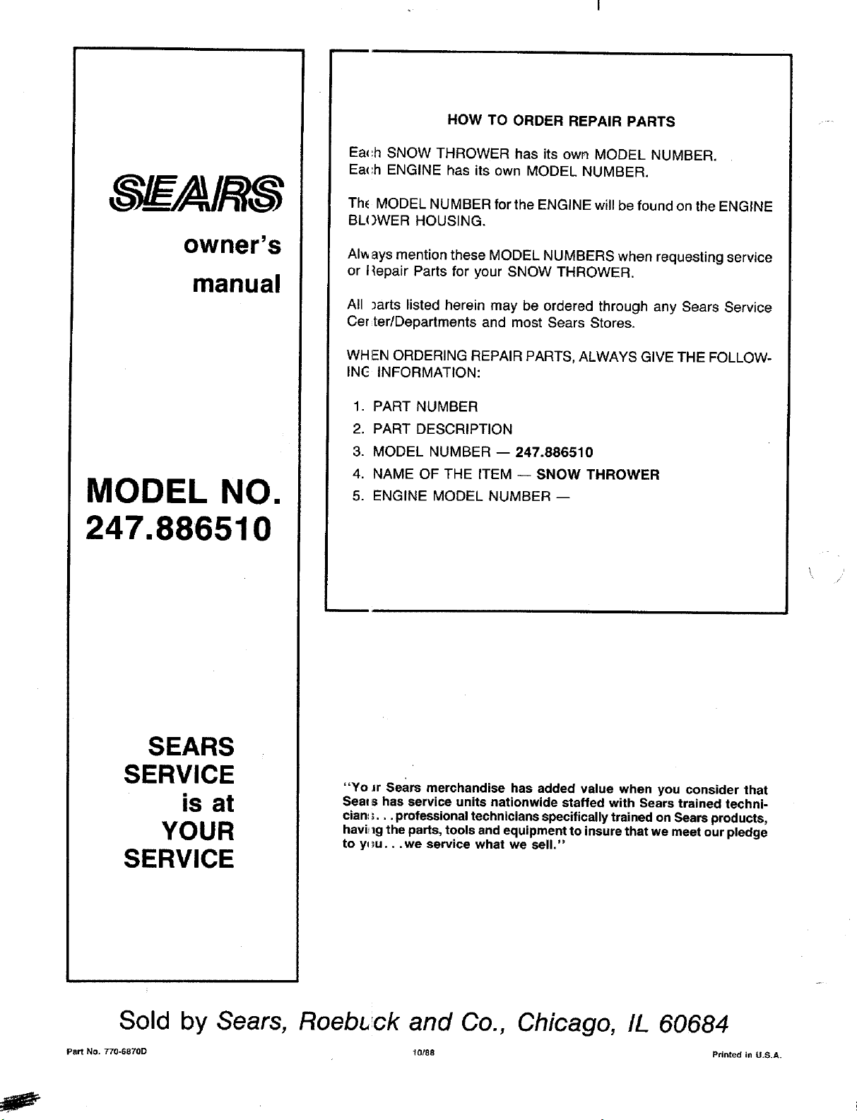
HOW TO ORDER REPAIR PARTS
Ea<:h SNOW THROWER has its own MODEL NUMBER.
Ea(',h ENGINE has its own MODEL NUMBER.
Th_ MODEL NUMBER for the ENGINE will be found on the ENGINE
BL()WER HOUSING.
AIways mention these MODEL NUMBERS when requesting service
or I_epair Parts for your SNOW THROWER.
All )arts listed herein may be ordered through any Sears Service
Cer ter/Departments and most Sears Stores.
WHEN ORDERING REPAIR PARTS, ALWAYS GIVE THE FOLLOW-
INC- INFORMATION:
1. PART NUMBER
2. PART DESCRIPTION
3. MODEL NUMBER -- 247.886510
4. NAME OF THE ITEM -- SNOW THROWER
5. ENGINE MODEL NUMBER --
"Yo Jr sears merchandise has added value when you consider that
Seat s has service units nationwide staffed with Sears trained techni-
cian, S... professional technicians specifically trained on Sears products,
havirlg the parts, tools and equipment to insure that we meet our pledge
to y_u...we service what we sell."
/
,/
Sold by Sears, Roebl, ck and Co., Chicago, IL 60684
Part No. 770-6870D 10/88 Printed in U.S,A.
e