Loading ...
Loading ...
Loading ...
INSTALLATION
Check the appliance is electrically safe when you have nished.
28
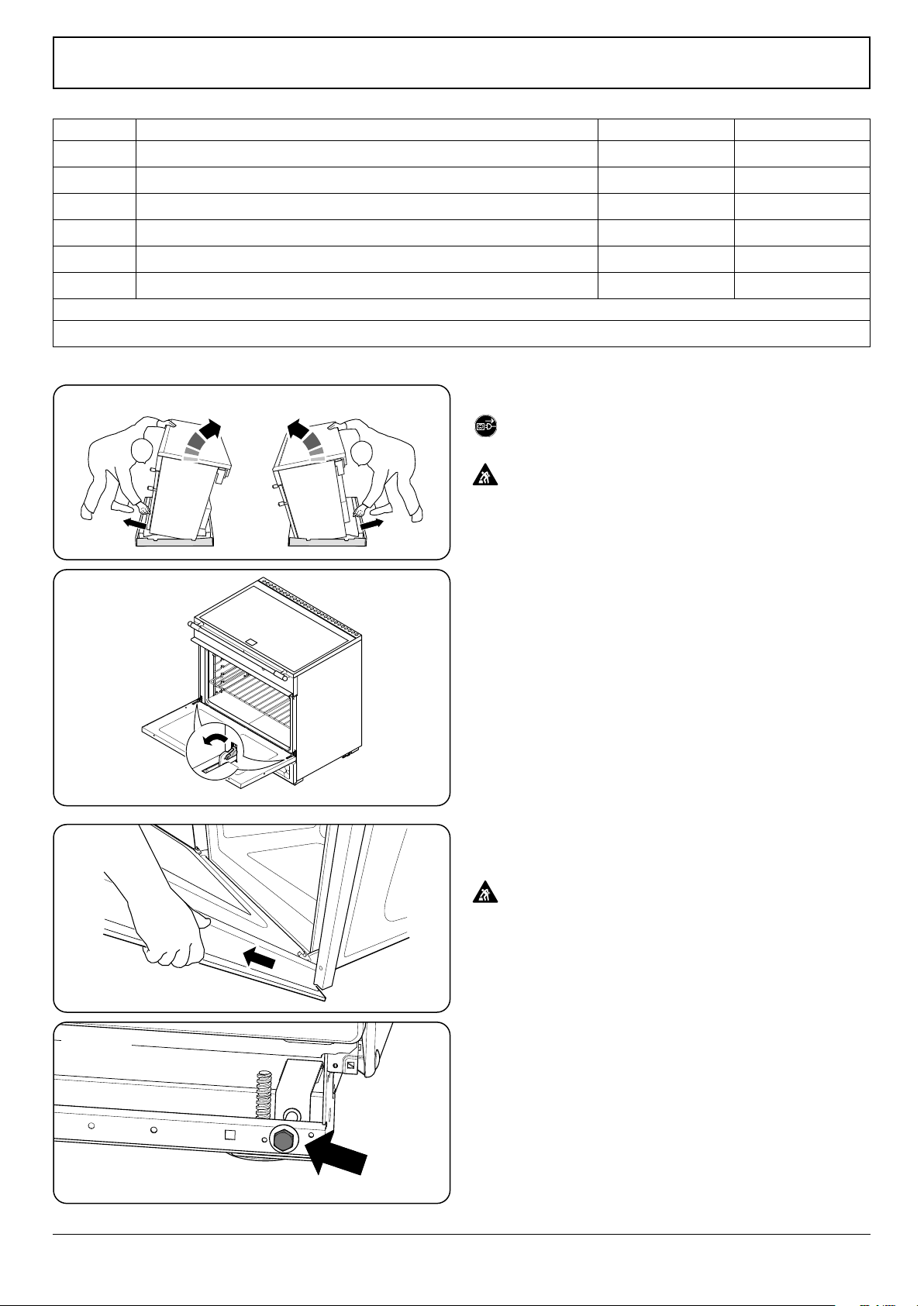
Fig. 10.5
Moving the range
On no account try and move the range while it is
plugged into the electricity supply.
This appliance is heavy. Ensure you have the correct
facilities to complete the move. To nd the weight of
the appliance refer to the "Technical data".
We recommend that two people manoeuvre the range. Make
sure that the oor covering is rmly xed, or removed, to
prevent it being disturbed when moving the range around.
To help you, there are two levelling rollers at the back, and
two screw-down levelling feet at the front.
Remove the polystyrene base pack. From the front, tilt the
range forward and remove the front half of the polystyrene
base (Fig. 10.5). Repeat from the back and remove the rear
half of the polystyrene base. Also remove cardboard base
tray.
Removing the door
Remove the oven door as follows: open the door fully. Swivel
the locking ‘U’ clips forward to the locking position (Fig. 10.6).
To remove the oven door, grip the sides of the door, lift
upwards and then slide the door forwards (Fig. 10.7) and
remove.
Door is very heavy - take care.
Lowering the two rear rollers
To adjust the height of the rear of the range, rst t a 13 mm
spanner or socket wrench onto the hexagonal adjusting nut
(Fig. 10.8). Rotate the nut – clockwise to raise – counter-
clockwise to lower.
Make 10 complete (360°) turns clockwise. Make sure you
lower BOTH REAR ROLLERS.
Unfold the rear edge of the cardboard base tray. Get a good
grip on the top of the oven cavity panel as you move the
oven. Carefully push the range backwards o the cardboard
base. Remove the base tray.
Fig. 10.6
Fig. 10.7
Fig. 10.8
Dimension Description USA Canada
A
Gap between side of appliance and adjacent vertical surface ABOVE cooktop level 1 ⁄" (30 mm) 1 ⁄" (30 mm)
B
Gap between side of appliance and adjacent vertical surface BELOW cooktop level ⁄" (5 mm) ½" (12 mm)
C
Gap between cooktop level and any horizontal combustible surface 31 ½" (800 mm) 31 ½" (800 mm)
D
Maximum depth of cabinets installed above the top surface cooking sections 13" (330 mm) 13" (330 mm)
E
Minimum distance between horizontal surfaces less than dimension C 35 ½" (902 mm) 36 ⁄" (918 mm)
F
Minmum distance between horizontal cabinets and worktop surfaces adjacent to range 16 ⁄" (410 mm) 16 ⁄" (410 mm)
1. For non-combustible surfaces (such as unpainted metal or ceramic tiles) this gap is not required
2. This dimension can be reduced to 24" (610 mm) if the bottom of the wooden or painted metal cabinet is preserved with a non-combustible material
Table 10.1
Clearances to Combustibles
Loading ...
Loading ...
Loading ...