Loading ...
Loading ...
3
INSTALLATION INSTRUCTIONS
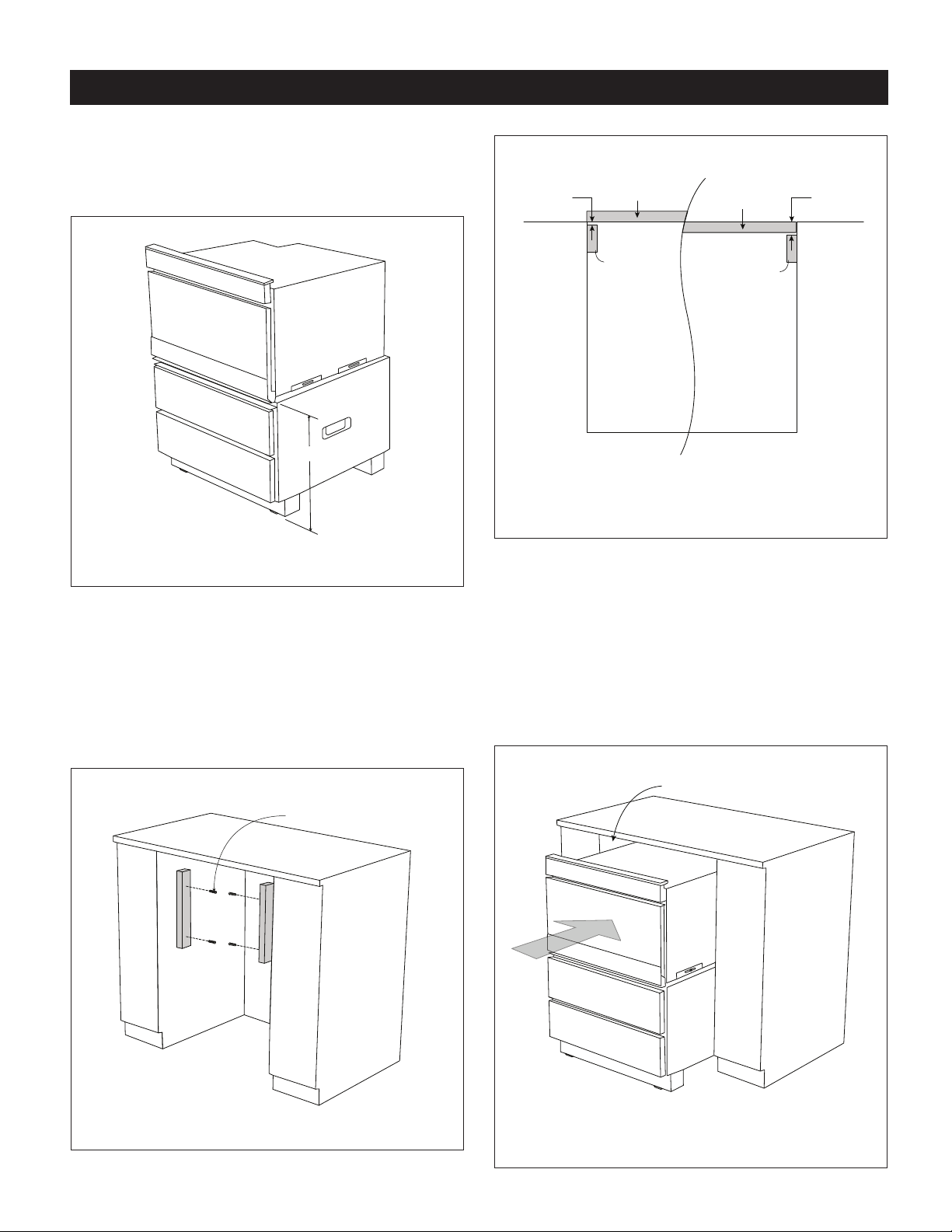
5. Once the overall height has been conrmed, measure the
distance from the top surface of the pedestal unit to the
oor. See Figure 5. This measurement will be needed for
the installation of the wooden mounting cleats.
A
FIGURE 5
6. Install the wooden cleats. Align the bottom of the cleat
to the measurement from Step 5. The pedestal can be
installed ush or standard with the face of the cabinet.
Depending on the preference, the depth of the cleat
position should be adjusted as such. See Figure 6.
Position each cleat and mark the holes on the cabinet.
Pre-drill each hole in the cabinet using a
1
/16" drill bit.
Attach both cleats using the 4 mounting cleat screws. See
Figure 7.
MOUNTING CLEAT SCREWS
FIGURE 6
X
Y
STANDARD MOUNT
CLEAT
CLEAT
FLUSH MOUNT
CABINET FACE
CABINET FACE
UTC DRAWER FACE
UTC DRAWER FACE
*NOTE: WHEN USING CONTRACTOR CABINET FACES,
ADD OR SUBTRACT ADDITIONAL DIMENSION.
SUPPLIED DRAWER FACES ARE 1”
FIGURE 7
7. Slide the unit into the opening. Plug the Microwave Drawer
into the wall receptacle prior to pushing the unit all the way
in. See Figure 8. The mounting angles of the Microwave
Drawer should rest against the installed wooden cleats.
NOTE: To aid in sliding the unit into the space, open the
bottom drawer and use middle frame to push into place.
In addition, there are built-in handles on each side of the
pedestal that can assist in the movement of the unit.
Tuck cord behind the oven before pushing the assembled
unit in.
*NOTE: ATTACH FILLER IF NEEDED
LEVEL UNIT TO DESIRED HEIGHT
FIGURE 8
Loading ...