Loading ...
2
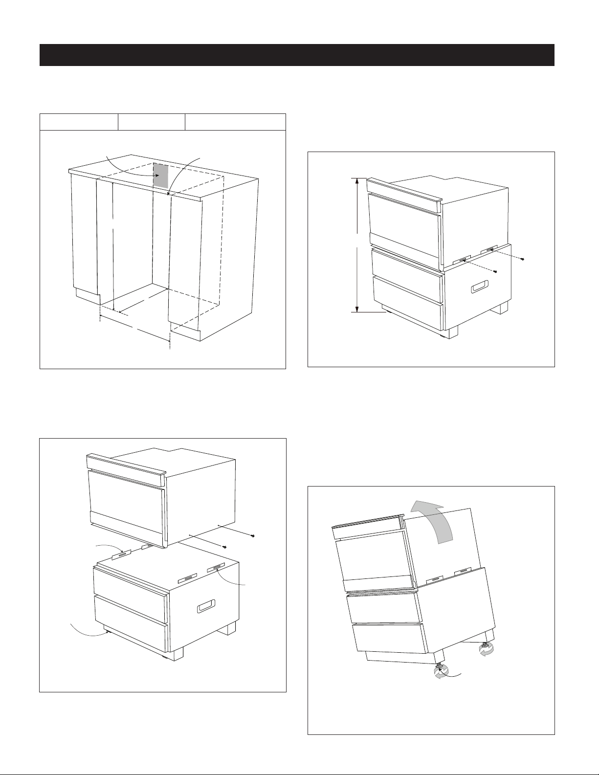
1. Cabinet cutout dimensions. Prepare the cabinet opening
as shown in Figure 1.
Height (A) 34
1
/2" Width (B) 24" Depth (C) 23
1
/2" min.
*NOTE: INSTALLER PROVIDE
TOP FILLER IF NEEDED
SUGGESTED ELECTRICAL
OUTLET LOCATION
B
C
A
FIGURE 1
2. Place the Microwave Drawer on a secure surface.
Remove the 4 bottom screws (2 on each side) of the
Microwave Drawer as shown in Figure 2. Carefully place
the Microwave Drawer on top of the pedestal in-between
the mounting rails on the left and right.
ADJUSTABLE
FEET
LEFT
MOUNTING
RAILS
RIGHT
MOUNTING
RAILS
FIGURE 2
*
Refer to the Microwave Drawer installation instructions
for the models' specic below-the-counter clearance
guidelines.
INSTALLATION INSTRUCTIONS
3. Align the front face of the Microwave Drawer with the
front face of the pedestal drawers.
Once positioned, fasten the Microwave Drawer to the
pedestal using the same 4 screws from Step 2. See
Figure 3.
*
FIGURE 3
4. Adjust the height of the overall unit to t your specic
opening. The pedestal contains 4 adjustable feet. To
adjust, have one person tilt the unit to one side while the
other person adjusts the 2 feet on the raised side to the
desired height. Repeat this step by tilting the unit to the
other side and adjusting the other 2 feet. Ensure that all
feet are adjusted equally to balance the unit. See Figure 4.
CAUTION: Do not tilt forward. The pedestal drawers will
extend out.
Use channel lock or
slip-joint pliers to loosen
the feet prior to
adjustment.
FIGURE 4
Loading ...
Loading ...