Loading ...
Loading ...
Loading ...
9
L
R
5
4
11
78
103
102
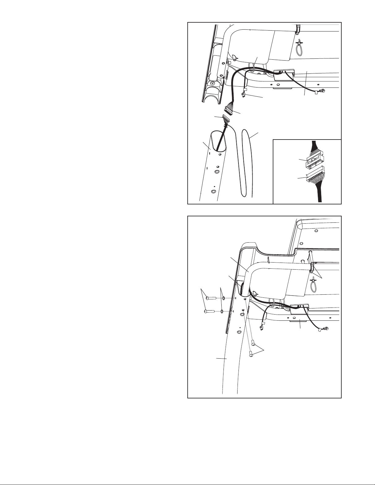
5. Insert the Upright Wire (78) into the right Upright
(77) as you insert the Console Crossbar (101)
into the Uprights. Be careful not to pinch the
Upright Wire.
Loosen the four #8 x 1" Screws (102) (only two
are shown) one turn.
Tighten two 5/16" x 2 1/2" Screws (4) with two
5/16" Star Washers (9) into the side of the right
Upright (77) and into the Crossbar (103). Do
not overtighten the Screws. Be careful not to
pinch the Upright Wire (78).
Next, tighten two 5/16" x 5/8" Screws (11) into
the right Upright (77) and the Console Crossbar
(101). It may be necessary to slide the
Console Crossbar (101) to align the holes.
Then, tighten the two #8 x 1" Screws (102).
Repeat this step on the other side of the
incline trainer.
4. Have a second person hold the console assem-
bly near the Uprights (77). Insert the console
wire and the “R” pulse wire from the console
assembly through the indicated tie.
Connect the Upright Wire (78) to the console
wire. See the inset drawing. The connectors
should slide together easily and snap into
place. If they do not, turn one connector and try
again. IF YOU DO NOT CONNECT THE CON-
NECTORS PROPERLY, THE CONSOLE MAY
BECOME DAMAGED WHEN YOU TURN ON
THE POWER.
Remove the wire tie from the Upright Wire (78).
R
L
4
78
Console
Wire
Console
Wire
78
Wire Tie
Tie
“R” Pulse
Wire
Console
Assembly
9
77
101
77
Loading ...
Loading ...
Loading ...