Loading ...
Loading ...
Loading ...
17
ENGLISH
PART 2: MOTOR INSTALLATION GUIDE
IN ROOF SOLUTION
Positioning your In-Roof Unit:
It is recommended that the In-Roof motor unit be mounted in a roof space or
wall cavity. Please ensure that the In-Roof motor unit is positioned in an environ-
ment that is free of other gases to enable an effi cient expulsion of the cooking
by-products and to ensure that back draft of external gases doesn’t take place.
Please ensure the motor is positioned away from other exhausts such as replace
chimneys, gas fuses, etc. The in roof unit can be mounted so that it ducts directly
through the wall or eave.
STEP 1:
Establish a suitable position in the roof or wall cavity for the In-Roof motor unit,
ensuring that the distance between the Roof motor unit and the outside vent is
under 800 mm. The In-Roof motor unit must be located a minimum of 3 metres
from the hood unit.
STEP 2:
Using the mounting bracket and screws, mount the In-roof motor unit to a
beam, truss or another appropriate structures in the roof or wall space. Ensure
the direction of airfl ow is toward the outside. The direction of airfl ow is marked
on the In-roof motor unit.
STEP 3:
Cut a 205 mm diameter hole in the wall or eave to enable the mounting of the
external vent. Please ensure that the hole is cut in a practical position to enable
the Flexi Duct to be secured. Attach the Flexi Duct to the vent and then mount
vent to the wall or eave.
STEP 4:
Attach the Flexi Duct from the external vent to the outlet of the In-roof motor
unit using duct clamps. To minimise ineffi ciencies and noise ensure the duct is
pulled tight.
STEP 5:
Attach Flexi Duct from the In-roof motor unit to the rangehood using duct
clamps. Ensure that the duct is pulled tightly to ensure that FlexiDuct remains
fi rm and stable during operation. Avoid sharp bends in the duct. Gentle bends
in the ducting are recommended as it assists in muffl ing noise from the fan unit
back to the rangehood. If the FlexiDuct needs to be extended attach the two
FlexiDuct ends using a RigidDuct insert, secured by pipe clamps or duct tape.
STEP 6:
Attach the male plug of the In-roof motor unit to the female plug of the range-
hood to enable power supply to the fan motor unit.
An extension lead (not supplied) of up to fi ve meters may be added if required.
EXTERNAL ROOF SOLUTION METAL ROOF INSTALLATION
Inspection:
Ensure the unit has arrived in good condition and that the impeller will spin
freely.
This product is designed to be installed on a roof up to 45° pitch.
1. Installation of this product should be carried out by appropriately qualifi ed
persons.
2. Cut a hole in the roof 200 mm minimum (with regard to roof pitch angle)
diameter. The hole should be positioned adjacent to a rafter or other member
to facilitate the use of the mounting brackets (optional accessory). Ensure a
clean edge.
3. Cut a 190 mm diameter hole in the rubber roof fl ashing (optional accessory)
for fi tting over the rigid duct.
4. Slide the fl ashing over the rigid duct to the required position.
5. Check the fi t of the duct in the cut hole. The duct must be positioned vertical-
ly.
6. If satisfactory fasten the duct to the rafter or other support using the mount-
ing brackets (optional accessory).
7. Fit the fl ashing to the metal deck using suitable mounting screws.
8. Attach the fl exi duct leading from the rangehood to the bottom of the rigid
duct using the supplied duct clamps.
9. Connect the male power plug to the female plug connected to the range-
hood. An extension lead (purchased separately ) can be used if necessary if
the duct run has been extended.
Safety Considerations:
1. All connections must be in accordance with any local regulations.
2. Fans have automatic thermal cut out switches incorporated in the motor as
standard.
3. This product is not intended for use by persons (including children) with re-
duced sensory or mental capabilities, or lack of experience and knowledge,
unless they have been given supervision or instruction concerning use of the
product by a person responsible for their safety. Children should be supervi-
sed to ensure that they do not play with the product.
4. For duct or partition mount, precautions must be taken to avoid the back-fl ow
of gases into the room from the open fl ue of gas or other open-fi re appliances.
5. If the supply cord is damaged it must be replaced by the manufacturer, its
service agent or similarly qualifi ed persons in order to avoid a hazard.
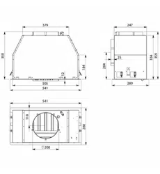
Mounting Bracket Outlet
Inlet
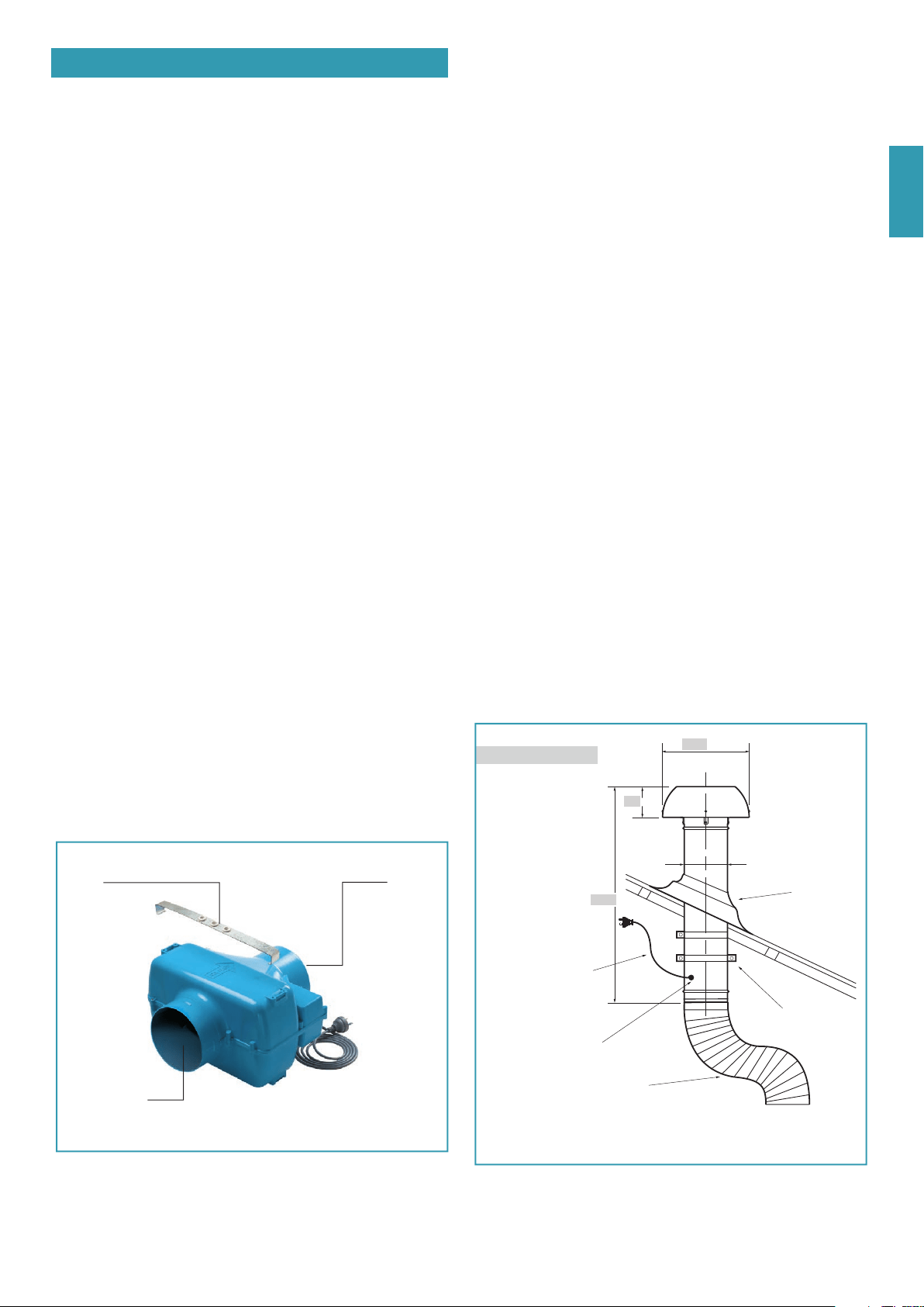
FLEXIBLE DUC T
FIT GROMME T
S UPPLIED
MOUNTING
BRA CKE TS
RUBBER ROOF
FLASHING
PO WER CA BLE 1200mm
ø403 / 44 5
ø194 DUCT
597.5 / 599
133 / 154
ER-765/1140 Dimensions
ER-2010 Dimensions
Loading ...
Loading ...
Loading ...