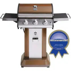
Use & Care Guide
Manual de Uso y Cuidado
English / Espa_ol
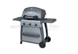
Models/Modelos: 148.16154211
Item / Articulo: 640-03838917-7
I(enmore
@
@
??rill?
@
Sears P/N 2818-2B, 2818-2R, 2818-2S & Kmart P/N 2818-2B-Manual
Sears Brands Management Corporation
Hoffman Estates, IL 60179 U.S.A.
www.kenmore.com
www.sears.com
www.kmart.com
If you smell gas:
1. Shut off gas to the appliance.
2. Extinguish any open flame.
3. Open lid.
4. If odor continues, keep away from the
appliance and immediately call your gas
supplier or your fire department.
1. Do not store or use gasoline or other
flammable liquids or vapors in the vicinity
of this or any other appliance.
2. An LP cylinder not connected for use shall
not be stored in the vicinity of this or any
other appliance.
CALIFORNIA PROPOSITION 65
1. Combustion by-products produced when
using this product contain chemicals knownto
the State of California to cause cancer, birth
defects, and other reproductive harm.
2. This product contains chemicals, including
lead and lead compounds, known to the State of
California to cause cancer, birth defects or other
reproductiveharm.
Wash your hands after handlinq this product.
Call Grill Service Center For Help And Parts
If you have questions or need assistance during assembly,
please call 1-800-482-0131. You will be speaking to a
representative of the grill manufacturerand not a Sears
employee. To order new parts call Sears at
1-800-4-MY-HOME.
Product Record
IMPORTANT: Fill out the product record information
below.
For residential use only. Do not use for
commercial cooking.
Installation Safety Precautions
• Use grill, as purchased, only with LP (propane) gas and the
regulator/valve assembly supplied. A conversion kit must
be purchased for use with natural gas.
• Grill installation must conform with local codes, or in their
absence of local codes, with either the Nationa/Fue/Gas
Code,ANSI Z223. 7/NFPA 54, Natural Gas and Propane
Installation Code, CSA B149. 1,or Propane Storage and
Handling Code, B149.2, or the Standard for Recreational
Vehicles,ANSI A I I9.2/NFPA 1192,and CSA Z240 RV
Series, Recreational Vehicle Code,as applicable.
• All electrical accessories (such as rotisserie) must be
electrically grounded in accordance with local codes, or
National Electrical Code,ANSI / NFPA 70 or Canadian
Electrical Code, CSA C22. 1. Keep any electrical cords
and/or fuel supply hoses away from any hot surfaces.
• This grill is safety certified for use in the United States
and/or Canada only. Do not modify for use in any other
location. Modification will result in a safety hazard.
Safety Symbols
The symbols and boxes shown below explain what each
heading means. Read and follow all of the messages found
throughout the manual.
DANGER: Indicates an imminently hazardous
situation which, if not avoided, will result in death or
serious injury.
WARNING: Indicates an potentially hazardous
situation which, if not avoided, could result in death
or serious injury.
Model Number: I-I148.16154211
I-I148.16154211
I-I148.16154211
Serial Number:
See rating label on grill for serial number.
Date Purchased:
CAUTION: Indicates a potentially hazardous
situation or unsafe practice which, if not avoided,
may result in minor or moderate injury.
© 2014KCDIP,LLC
2
For Your Safety .................................. 2
Grill Service Center............................... 2
Product Record Information ........................ 2
Safety Symbols.................................. 2
Installation Safety Precautions ....................... 2
Kenmore Grill Warranty ........................... 3
Use and Care ................................ 4-10
Natural Gas Conversion Box ...................... 11
Notes.......................................... 11
Parts List ...................................... 13
Parts Diagram................................... 14
Assembly .................................... 17-24
Conversion Instructions for 16154................. 25-27
Troubleshooting............................... 28-29
Repair Protection Agreements
Congratulations on making a smart purchase. Your new
Kenmore ®productis designed and manufactured for years of
dependable operation. But like all products, it may require
repair from time to time. That's when having a Repair
Protection Agreement can save you money and aggravation.
Purchase a Repair Protection Agreement now and protect
yourself from unexpected hassle and expense.
Here's what the Repair Protection Agreement includes:
[] Expert service by our 10,000 professional repair
specialists
[] Unlimited service and no charge for parts and labor on
all covered repairs
[] Product replacement up to $1500 if your covered
product can't be fixed
[] Discount of 25% from regular price of service and
related installed parts not covered by the agreement; also,
25% off regular price of preventive maintenance check
[] Fast help by phone- we call it Rapid Resolution -
phone support from a Sears representative. Think of us
as a "talking owner's manual."
Once you purchase the Repair Protection Agreement, a simple
phone call is all that it takes for you to schedule service. You
can call anytime day or night, or schedule a service
appointment online.
The Repair Protection Agreement is a risk-free purchase. If you
cancel for any reason during the productwarranty period, we
will provide a full refund. Or, a prorated refund anytime after
the product warranty period expires. Purchase your Repair
Protection Agreement today!
Some limitations and exclusions apply.
For prices and additional information call 1-800-827-6655.
Sears Installation Service
For Searsprofessionalinstallation of home appliances, garage
door openers, water heaters, and other major home items, in
the U.S.A. call 1-800-4-MY-HOME®
Kenmore Full Warranty
If this grill fails due to a defect in material or workmanship
within one year from the date of purchase, call 1-800-4-MY-
HOME® to arrange for free repair (or replacement if repair
proves impossible).
Limited Warranty on Burners
For ten years from the date of purchase, any stainless steel
burner that rusts through will be replaced free of charge. After
the first year from the date of purchase, you pay for labor if
you wish to have it installed.
All warranty coverage excludes ignitor batteries and grill part
paint loss, discoloration or rusting, which are either
expendable parts that can wear out from normal use within
the warranty period, or are conditions that can be the result
of normal use, accident or improper maintenance.
All warranty coverage is void if this grill is ever used for
commercial or rental purposes.
All warranty coverage applies only if this grill is used in the
United States.
This warranty gives you specific legal rights, and you may
also have other rights which vary from state to state.
Sears Brands Management Corporation,
Hoffman Estates, IL 60179

• NEVER store a spare LP cylinder under or near
the grill appliance or in an enclosed area.
ii_iii_iii_iii iiiii_i¸
• Never fill a cylinder beyond 80% full.
• If the information in the two points above is not
followed exactly, a fire causing death or serious
injury may occur.
• An over filled or improperly stored cylinder is a
hazard due to possible gas release from the
safety relief valve. This could cause an intense
fire with risk of property damage, serious injury
or death.
• If you see, smell or hear gas escaping,
immediately get away from the LP cylinder and
grill appliance and call your fire department.
LP Cylinder
• The LP cylinder used with your grill must meet the
following requirements:
• Use LP cylinders only with these required measurements: 12"
(30.5cm) (diameter) x 18" (45.7 cm) (tall) with 20 lb. (9 kg.)
capacity maximum.
• LP cylinders must be constructed and marked in accordance
with specifications for LP cylinders of the U.S. Department of
Transportation (DOT) or for Canada, CAN/CSA-B339,
cylinders, spheres and tubes for transportation of dangerous
goods. Transport Canada (TC). See LP cylinder collar for
marking.
• LP cylinder valve must have:
• Type 1 outlet compatible with
regulator or grill.
• Safety relief valve.
• UL listed Overfill Protection OPDHand Wheel
Device (OPD). This OPD safety
feature is identified by a unique triangular hand wheel. Use
only LP cylinders equipped with this type of valve.
• LP cylinder must be arranged for vapor withdrawal and
include collar to protect LP cylinder valve. Always keep LP
cylinders in upright position during use, transit or storage.
LP Tank Removal, Transport and Storage
• Turn OFF all control knobs and LP tank valve Turn coupling
nut counterclockwise by hand only - do not use tools to
disconnect. Lift LP tank wire upward off of LP tank collar, then
lift LP tank up and off of support bracket. Install safety cap
onto LP tank valve. Always use cap and strap supplied with
valve.
Failure to use safety cap as directed may result in
serious personal injury and/or property damage.
LPTankValve
@_ Safety Cap
Retainer Strap
• A disconnected LP tank in storage or being transported must
have a safety cap installed (as shown). Do not store an LP
tank in enclosed spaces such as a carport, garage, porch,
covered patio or other building. Never leave an LP tank inside
a vehicle which may become overheated by the sun.
• Do not store an LP tank in an area where children play.
LP cylinder in upright position for vapor withdrawal
LP (Liquefied Petroleum Gas)
• LP gas is nontoxic, odorless and colorless when produced.
For Your Safety, LP gas has been given an odor (similar to
rotten cabbage) so that it can be smelled.
• LP gas is highly flammable and may ignite unexpectedly
when mixed with air.
LP Cylinder Filling
• Use only licensed and experienced dealers.
• LP dealer must purge new cylinder before filling.
• Dealer should NEVER fill LP cylinder more than 80% of LP
cylinder volume. Volume of propane in cylinder will vary by
temperature.
• A frosty regulator indicates gas overfill. Immediately close LP
cylinder valve and call local LP gas dealer for assistance.
• Do not release liquid propane (LP) gas into the atmosphere.
This is a hazardous practice.
• To remove gas from LP cylinder, contact an LP dealer or call
a local fire department for assistance. Check the telephone
directory under "Gas Companies" for nearest certified LP
dealers.

LPTankExchange
•Manyretailersthatsellgrillsofferyoutheoptionofreplacing
youremptyLPtankthroughanexchangeservice.Useonly
thosereputableexchangecompaniesthatinspect,precision
fill,testandcertifytheircylinders.Exchangeyourtankonly
foranOPDsafetyfeature-equippedtankasdescribedin
the"LPTank"sectionofthismanual.
•AlwayskeepnewandexchangedLPtanksinuprightposition
duringuse,transitorstorage.
•LeaktestnewandexchangedLPtanksBEFORE
connectingtogrill.
LP Tank Leak Test
For your safety
•Leak test must be repeated each time LP tank is exchanged
or refilled.
•Do not smoke during leak test.
•Do not use an open flame to check for gas leaks.
•Grill must be leak tested outdoors in a well-ventilated area,
away from ignition sources such as gas fired or electrical
appliances. During leak test, keep grill away from open flames
or sparks.
•Use a clean paintbrush and a 50/50 mild soap and water
solution. Brush soapy solution onto areas indicated by arrows
in figure below. Leaks are indicated by growing bubbles.
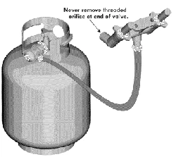
Connecting Regulator To The LP Tank
1. LP tank must be properly secured onto grill. (Refer to
assembly section.)
2. Turn all control knobs to the OFF position.
3. Turn LP tank OFF by turning OPD hand wheel clockwise to
a full stop.
4. Remove the protective cap from LP tank valve. Always use
cap and strap supplied with valve.
OPDHand Wheel
Type1outletwith
threadon outside
Safety Relief Valve
/
Strap and Cap
If "growing" bubbles appear do not use or move the LP
tank. Contact an LP gas supplier or your fire department!
Do not insert a POL transport plug
(plastic part with external threads)
into the Type 1 tank valve outlet. It
will defeat the Safety Relief Valve
feature.
• Do not use household cleaning agents. Damage to gas
train components (valve/hose/regulator) can result.
5. Hold regulator and insert nipple into LP tank valve.
Hand-tighten the coupling nut, holding regulator in a straight
line with LP tank valve so as not to crossthread the
connection.
Nipple has to be centered
into the LP tankvalve.
/
S
s
,f
/

Hold coupling nut and regulator
as shown for proper connection
to LP tank valve.
6. Turn the coupling nut clockwise and tighten to a full stop.
The regulator will seat on the back-check feature in the LP
tank valve, resulting in some resistance. An additional
one-half to three-quarters turn is required to complete
the connection. Tighten by hand only - do not use tools.
Leak Testing Valves, Hose and Regulator
1. Turn all grill control knobs to OFF.
2. Be sure regulator is tightly connected to LP tank.
.
Completely open LP tank valve by turning OPD hand wheel
counterclockwise. If you hear a rushing sound, turn gas off
immediately. There is a major leak at the connection.
Correct before proceeding by calling Sears for
replacement parts at 1-800-4-MY-HOME®.
4. Brush soapy solution onto areas where bubbles are shown
in picture below:
• Neverremovethreaded
orifice at end of valve.
NOTE:
If you cannot complete the connection, disconnect regulator
and repeat steps 5 and 6. If you are still unable to complete the
connection, do not use this regulator! Call 1-800-482-0131
for assistance.
• Do not insert any tool or foreign object into the valve
outlet or safety relief valve. You may damage the valve
and cause a leak. Leaking propane may result in
explosion,fire, severe personal injury,or death.
• Outdoor gas appliance is not intended to be installed
in or on a boat.
• Outdoor gas appliance is not intended to be installed
in or on an RV.
• Never attempt to attach this grill to the self-contained
LP gas system of a camper trailer or motor home.
• Do not use grill until leak-tested.
• If a leak is detected at any time, STOP and call the
fire department.
• If you cannot stop a gas leak, immediate/yclose
LPcylinder valve and call LP gas supplier or your fire
department!
5. If "growing" bubbtesappear, there is a leak. Close LP tank
valve immediately and retighten connections. If leaks
cannot be stopped do not try to repair. Call Sears for
replacement parts at 1-800-4-MY-HOME®.
6. Always close LP tank valve after performing leak test by
turning hand wheel clockwise.

For Safe Use of Your Grill and to Avoid Serious
Injury:
• Do not let children operate or play neargrill.
• Keep grill area clear and free from materials that
burn.
• Do not block holes in sides or back of grill.
• Check burnerflames regularly.
• Use grill only in well-ventilated space. NEVER use in
enclosedspace such as carport, garage, porch,
covered patio, or under an overhead structure of any
kind.
• Do not use charcoal or ceramic briquets in a gas grill.
(Unless briquets are supplied withyour grilL)
• Use grill at least 3 ft. from any wall or surface.
Maintain 10 ft. clearance to objects that can catch
fire, or to sources of ignition such as pilot lights on
water heaters, live electrical appliances, etc.
• Apartment Dwellers:
Check with managementto learn the requirements
and fire codes for using an LP gas grill in your
apartment complex. If allowed, use outside on the
ground floor with a three (3) foot clearance from walls
or rails. Do not use on or under balconies.
• NEVER attempt to light burner with lid closed. A
buildup of non-ignited gas inside a closed grill is
hazardous.
• Never operate grill with LP cylinder out of correct
position specified in assembly instructions.
• Always close LP cylinder valve and remove
coupling nut before moving LP cylinder from
specified operation position.
Safety Tips
• Before opening LP cylinder valve, check the coupling nut
for tightness.
• When grill is not in use, turn off all control knobs and LP
cylinder valve.
• Never move grill while in operation or still hot.
• Use long-handled barbecue utensils and oven mitts to
avoid burns and splatters.
• Maximum load for sideburner and side shelf is 10 Ibs.
• The grease tray must be inserted into grill and emptied
after each use. Do not remove grease tray until grill has
completely cooled.
• Clean grill often, preferably after each cookout. If a bristle
brush is used to clean any of the grill cooking surfaces,
ensure no loose bristles remain on cooking surfaces prior
to grilling. It is not recommended to clean cooking surfaces
while grill is hot.
• If you notice grease or other hot material dripping from grill
onto valve, hose or regulator, turn off gas supply at once.
Determine the cause, correct it, then clean and inspect
valve, hose and regulator before continuing. Perform a
leak test.
• Keep ventilation openings in cylinder enclosure (grill cart)
free and clear of debris.
• Do not store objects or materials inside the grill cart
enclosure that would block the flow of combustion air to the
underside of either the control panel or the firebox bowl.
• The regulator may make a humming or whistling noise
during operation. This will not affect safety or use of grill.
• If you have a grill problem see the "Troubleshooting
Section".
• If the regulator frosts, turn off grill and LP cylinder valve
immediately. This indicates a problem with the cylinder and
it should not be used on any product. Return to supplier!
CAUTION
• Putting out grease fires by closing the lid is not
possible. Grills are well ventilated for safety reasons.
• Do not use water on a grease fire. Personal injury may
result. If a grease fire develops, turn knobs and LP
cylinder off.
• Do not leave grill unattended while preheating or
burning off food residue on HI. If grill has not been
regularly cleaned, a grease fire can occur that may
damage the product.
Ignitor Lighting the Grill
1. Read instructions before lighting your grill.
2. Open lid during lighting.
3. Open LP cylinder or natural gas valve.
4. Push any burner control knob in and turn the knob to the left
to "HI" position. Keep pressing the knob until the burner is
lit.
5.Ifignitiondoesnotoccurin5seconds,turntheburner
controloff,wait5 minutesforgastoclearaway,andrepeat
thelightingprocedure.
6.Tolightotherburners,repeatstep4.
NOTE:If ignitordoesnotwork,followMatchLighting
instructions.
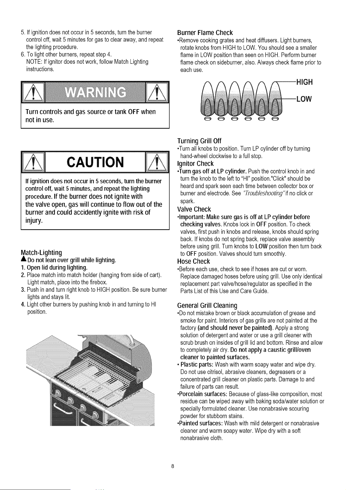
BurnerFlameCheck
•Removecookinggratesandheatdiffusers.Lightburners,
rotateknobsfromHIGHtoLOW.Youshouldseeasmaller
flameinLOWpositionthanseenonHIGH.Performburner
flamecheckonsideburner,also.Alwayscheckflamepriorto
eachuse.
3H
Turn controls and gas source or tank OFF when
not in use.
If ignition does not occur in 5 seconds, turn the burner
control off, wait 5 minutes, and repeat the lighting
procedure. If the burner does not ignite with
the valve open, gas will continue to flow out of the
burner and could accidently ignite with risk of
injury.
Match-Lighting
• Do not lean over grill while lighting.
1. Open lid during lighting.
2. Place match into match holder (hanging from side of cart).
Light match, place into the firebox.
3. Push in and turn right knob to HIGH position. Be sure burner
lights and stays lit.
4. Light other burners by pushing knob in and turning to HI
position.
Turning Grill Off
•Turn all knobs to position. Turn LP cylinder off by turning
hand-wheel clockwise to a full stop.
Ignitor Check
•Turn gas off at LP cylinder. Push the control knob in and
turn the knob to the left to "HI" position."Click" should be
heard and spark seen each time between collector box or
burner and electrode. See "Troub/eshooting'if no click or
spark.
Valve Check
•Important: Make sure gas is off at LP cylinder before
checking valves. Knobs lock in OFF position. To check
valves, first push in knobs and release, knobs should spring
back. If knobs do not spring back, replace valve assembly
before using grill. Turn knobs to LOW position then turn back
to OFF position. Valves should turn smoothly.
Hose Check
•Before each use, check to see if hoses are cut or worn.
Replace damaged hoses before using grill. Use only identical
replacement part valve/hose/regulator as specified in the
Parts List of this Use and Care Guide.
General Grill Cleaning
•Do not mistake brown or black accumulation of grease and
smoke for paint. Interiors of gas grills are not painted at the
factory (and should never be painted). Apply a strong
solution of detergent and water or use a grill cleaner with
scrub brush on insides of grill lid and bottom. Rinse and allow
to completely air dry. Do not apply a caustic grill/oven
cleaner to painted surfaces.
• Plastic parts: Wash with warm soapy water and wipe dry.
Do not use citrisot, abrasive cleaners, degreasers or a
concentrated grill cleaner on plastic parts. Damage to and
failure of parts can result.
•Porcelain surfaces: Because of glass-like composition, most
residue can be wiped away with baking soda/water solution or
specially formulated cleaner. Use nonabrasive scouring
powder for stubborn stains.
•Painted surfaces: Wash with mild detergent or nonabrasive
cleaner and warm soapy water. Wipe dry with a soft
nonabrasive cloth.
•Stainlesssteelsurfaces:Tomaintainyourgrill'shighquality
appearance,washwithmilddetergentandwarmsoapywater
andwipedrywithasoftclothaftereachuse.Baked-on
greasedepositsmayrequiretheuseofanabrasiveplastic
cleaningpad.Useonlyindirectionofbrushedfinishtoavoid
damage.Donotuseabrasivepadonareaswithgraphics.
• Cookingsurfaces:Ifabristlebrushisusedtocleananyof
thegrillcookingsurfaces,ensurenoloosebristlesremainon
cookingsurfacespriortogrilling.Itisnotrecommendedto
cleancookingsurfaceswhilegrillishot.
CleaningtheBurnerAssembly
Followtheseinstructionstocleanand/orreplacepartsof
burnerassemblyorifyouhavetroubleignitinggrill.
1.TurngasoffatcontrolknobsandLPcylinder.
2.Removecookinggratesandheatdiffusers.
3.RemoveRpinsfromrearofburners.
4.Carefullylifteachburnerupandawayfromvalveopenings.
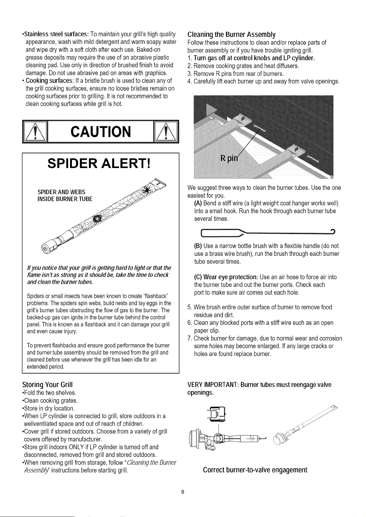
SPIDER ALERT!
Ifyou notice thatyour grill is getting hard to light or that the
flame isn't as strong as it should be, take the time to check
and clean the burner tubes.
Spidersor smallinsectshave beenknownto create"flashback"
problems.Thespidersspinwebs,buildnestsand lay eggsin the
grill's burnertubesobstructingtheflow of gasto the burner.The
backed-upgascan igniteinthe burnertube behindthe control
panel.Thisis knownas a flashbackand it candamageyour grill
andevencauseinjury.
To preventflashbacksandensuregoodperformancethe burner
and burnertubeassemblyshouldbe removedfromthe grilland
cleanedbeforeusewheneverthe grillhas beenidlefor an
extendedperiod,
We suggest three ways to clean the burner tubes. Use the one
easiest for you.
(A) Bend a stiff wire (a light weight coat hanger works well)
into a small hook. Run the hook through each burner tube
several times.
(B) Use a narrow bottle brush with a flexible handle (do not
use a brass wire brush), run the brush through each burner
tube several times.
(C) Wear eye protection: Use an air hose to force air into
the burner tube and out the burner ports. Check each
port to make sure air comes out each hole.
5. Wire brush entire outer surface of burner to remove food
residue and dirt.
6. Clean any blocked ports with a stiff wire such as an open
paper clip.
7. Check burner for damage, due to normal wear and corrosion
some holes may become enlarged. If any large cracks or
holes are found replace burner.
Storing Your Grill
•Fold the two shelves.
•Clean cooking grates.
•Store in dry location.
•When LP cylinder is connected to grill, store outdoors in a
wellventilated space and out of reach of children.
•Cover grill if stored outdoors. Choose from a variety of grill
covers offered by manufacturer.
•Store grill indoors ONLY if LP cylinder is turned off and
disconnected, removed from grill and stored outdoors.
•When removing grill from storage, follow "C/eaning the Burner
,4ssembl_' instructions before starting grill.
VERY IMPORTANT: Burner tubes must reengage valve
openings.
Correct burner-to-valve engagement

Indirect Cooking
Poultry and large cuts of meat cook slowly to perfection on the
grill by indirect heat. Place food over unlit burner(s); the heat
from lit burners circulates gently throughout the grill, cooking
meat or poultry without the touch of a direct flame.
This method greatly reduces flare-ups when cooking extra fatty
cuts because there is no direct flame to ignite the fats and
juices that drip during cooking.
1 Burner Cooking
Cook with direct or indirect heat.
Best for smaller meals or foods.
Consumes less fuel.
thermometer to ensure proper internal food temperatures.
Chill: Refrigerate prepared foods and leftovers promptly.
For more information call: USDA Meat and Poultry Hotline
at 1-800-535-4555 (In Washington, DC (202) 720-3333, 10:00
am-4:00 pm EST).
How To Tell If Meat Is Grilled Thoroughly
• Meat and poultry cooked on a grill often browns very fast on
the outside. Use a meat thermometer to be sure food has
reached a safe internal temperature, and cut into food to
check for visual signs of doneness.
• Whole poultry should reach 180° F; breasts, 170° F. Juices
should run clear and flesh should not be pink.
• Hamburgers made of any ground meat or poultry should
reach 160° F, and be brown in the middle with no pink juices.
Beef,veal and lamb steaks, roasts and chops can be cooked
to 145°F. All cuts of pork should reach 160° F.
• NEVER partially grill meat or poultry and finish cooking later.
Cook food completely to destroy harmful bacteria.
• When reheating takeout foods or fully cooked meats like hot
dogs, grill to 165° F, or until steaming hot.
Indirect Cooking Instructions
• Always cook with the lid closed.
• Due to weather conditions, cooking times may vary.
During cold and windy conditions the temperature setting
may need to be increased to insure sufficient cooking
temperatures.
• Place food over unlit burner(s)
WARNING: To ensure that it is safe to eat, food must be
cooked to the minimum internal temperatures listed in the table
below.
USDA* Recommended Safe Minimum Internal
Temperatures
Beef, Veal, Lamb and Pork - Whole Cuts** 145 ° F
Fish 145° F
Beef, Veal, Lamb and Pork - Ground 160° F
Egg Dishes 160° F
Turkey, Chicken & Duck - Whole, Pieces &
165° F
Ground
United States Department of Agriculture
**Allow meat to rest three minutes before carving or
consuming.
2 Burner Cooking
Great indirect cooking on tow.
Produces slow, even heating.
Ideal for slow roasting and baking.
Food Safety
Food safety is a very important part of enjoying the outdoor
cooking experience. To keep food safe from harmful bacteria,
follow these four basic steps:
Clean: Wash hands, utensils, and surfaces with hot soapy
water before and after handling raw meat and poultry.
Separate: Separate raw meats and poultry from ready-to-eat
foods to avoid cross contamination. Use a clean platter and
utensils when removing cooked foods.
Cook: Cook meat and poultry thoroughly to kill bacteria. Use a
10

To purchase a Natural Gas Conversion Kit call Sears at
1-800-4-MY-HOME®
Natural gas conversion kit
Kenmore Model # 10478
(Manufacturer Part No.: 2818-2T-KIT)
Your grill can be converted to natural gas with this
conversion kit by a qualified gas technician only. In order
to convert this grill the technician will need this
conversion kit.
The kit contains orificesfor various grill models. Please
select the orifices as listed below and discard the rest.
Follow the conversion instruction provided with the kit.
Natural Gas Connection Preparation:
1. Turn off gas supply, and then remove cap on gas
supply side.
2. Recommended: Install a shut-off valve on
gas supply side before installing the socket.
3. Socket should be installed by an authorized
technician in accordance with the national fuel gas
code (NFPA54/ANSI223.1).
4. Before inserting plug, turn on gas supply and leak
test all connections including the stem of the shut-off
valve and the opening of the socket. For best results,
use an ammonia-free soap & water solution.
Operating Instructions:
1. To connect, push back socket sleeve.
Model Main Burner1.37 mm
148.16154211
148.16154211 4
148.16154211
12 ft. extension hose with 3/8 in. ID (inner diameter)
If converting the grill to natural gas, the technician in
most cases will need this 12 ft. extension hose with 3/8"
ID (inner diameter), which is included in the natural gas
conversion kit.
Socket Sleeve __ Plug
2. Insert plug and release sleeve.
3. Push plug until sleeve snaps forward. (Gas will flow
automatically.Failure to connect plug properly to
socket will inhibit gas flow to the appliance.)
Socket Sleeve
To disconnect
1. Pull Sleeve back. Pull plug out of socket. (Gas is
automaticallyshut off.)
2. Close shut-off valve or turn off gas supply, and
replacedust caps on socket and plug.
Gas Requirements
LP Gas
Now that your grill is converted to Natural Gas use, it is
set for 7-inch water column (WC) pressure, and cannot
be used with Propane Gas. The factory-supplied
regulator and hose must be used with a 20-lb. LP gas
tank.
11

Natural Gas
If your grill is for Natural Gas, it is set for a 7-in. water
column (WC) and is for usewith Natural Gas only. Gas
pressure is affected by gas line size and the length of
gas line run from house gas line. Follow the
recommendations in the chart below.
From Houseto Grill
Distance Tubing Size
Upto 25 ft. 3/8 in. diameter
26-50 ft. 1/2 in. diameter
2/3 of the run: 3/4 in. diameter
51-100ft.
1/3of the run :1/2 in. diameter
Over 101 ft. 3/4 in. diameter
CAUTION:
If low flames or burner problems are witnessed after
converting from LPG to NG, the natural gas lines may not
be large enough. Refer to the "From House to Grill" chart
on page 12 for natural gas supply line specifications.
Please contact a plumber to assure proper pressureat 7
in. water column.
Do not return your grill to the store.
Excess Flow Control and Low Heat
The propane regulator assembly incorporates an excess
flow device designed to supply the grill with sufficient gas
flow under normal conditions yet control excess gas flow.
Rapid changes in pressure can trigger the excessflow
device providing a low flame and low temperature. If the
tank valve is turned open to allow gas flow while a burner
valve is open, the surge of pressurewill cause the device
to activate. The device will remain closed until the
pressure is equalized. This should occur within 5
seconds.
To ensure this does not cause difficulty in lighting the grill,
follow these instructions:
1. Make sure all burner valves are "OFF".
2. Open the tank valve and wait 5 seconds.
3. Light the burners one at a time following the lighting
instructions.
Always protect your hand with a pot holder or cooking
glove when coming into contact with a hot surface.
Hood up when grilling meats, especially chicken. Hood
down when indirect or rotisserie cooking.
NEVER leave your grill unattendedwhile cooking.
After use, close hood, turn burnersto HIfor 15 min. for
self-cleaning, grease burn off.
Care and MaintenanceTime TableChart
GrillItem FrequencyBased
on NormalUse CleaningMethod
Paintedsurface Twiceyearly Car wax
Stainlesssurface Twiceyearly Stainlesscleaner
All grates After each use Burnoff andwipe
Wire brush/
Stainlessgrates 15 days Dishwashersafe
Scrub pad soapy water
Porcelaingrates 15 days /Dishwashersafe
Burnerheat tents 30 days Wire brush
Burners 90 days Wire brush
Burnerbox Interiorgrill cleaning
120days products(availableat
interior Sears)
Helpful Care and Maintenance Hints
Before grilling, pre-heat grill for 15 minutes on "HI" with
hood down. To avoid uncontrolled flare-ups or grease
fires, grill meats with hood open. Close hood if meats are
thick or weather is cold, or if you are using a rotisserieor
indirect cooking.
12

Key
1
2
3
4
5N
6
7
8
9
10
11
12
13
14
15-1
15-2
15-3
15-4
16
17
18
19N
20
21N
21N-1
25
26N
27
28
29
30
31
32
33
34
35
36
37N-1
37N-2
37N-3
38N-1
Oty Description
1 HOODHANDLE
2 HANDLEBASE
2 SCREW
4 RUBBERGASKET
1 HOOD
2 SCREW
2 BUSHING
2 FLANGENUT
1 TEMPERATUREGAUGE
1 WASHER,TEMPERATURE
GAUGE
1 NUT
4 HEATDIFFUSER
2 COOKINGGRIDS
1 WARMINGRACK
1 IGNITIONPIN( MAINBURNER)
1 IGNITIONPIN( MAINBURNER)
1 IGNITIONPIN( MAINBURNER)
1 IGNITIONPIN( MAINBURNER)
4 PIN
4 MAIN BURNER
16 SCREW
1 BURNERBOX
1 WINDSHIELD
1 RIGHTWINGTABLEASSE
1 RIGHTWINGTABLE
1 IGNITIONSWITCHWIRE
1 MANIFOLD,MAINBURNER
1 LP GAS REGULATOR
1 REARPANEL
1 RIGHTPANELASSEMBLY
1 BEAM
1 RIGHTANGLE BRACKET
2 CASTER,LOCKING
2 CASTER
1 WING-HEADSCREW
1 SCREWW/SHOULDER
1 MATCHHOLDER
1 DOOR(R-BLACK)
1 DOOR(R-RED)
1 DOOR(R-STAINLESSSTEEL)
1 DOOR(L-BLACK)
Manufacturer
Part #
2818-2T-6200
RB2818C-00-4001
1/4-20x5/8in.
3219B-8083
2818-2T-6000
5/16-18x3/4in.
2818-2T-0001
5/16-18
2818-2T-A301
2518SL-6002
5/16-18
2818-2T-2007
2818-2T-2001
2818-2T-2002
2818-2T-A500-4/1
2818-2T-A500-4/2
2818-2T-A500-4/3
2818-2T-A500-4/4
1.6x30
SH3118B-2004
5/32-32x3/8in.
2818-2T-2000
2818-2T-2004
2818-2T-5000-2
2818-2T-5100-2
2818-2T-A400
2818-2B-3200
SH3118B-3003
2818-2T-1002
2818-2T-1400-2
2818-2T-1200
2818-2T-1700
2518-3-8007
2518-3-8008
1/4-20x2in.
5/32-32x3/8in.
301%-1710
2818-2T-8000
2818-2R-8000
2818-2S-8000
2818-2T-7000
Key qty Description
38N-2 1 DOOR(L-RED)
38N-3 1 DOOR(L-STAINLESSSTEEL)
39N 1 BOTTOMPANELASSEMBLY
40 31 SCREW
41 1 LEFTANGLEBRACKET
42 3 MAGNET
43 1 MAGNETHOUSING
44 2 SCREW
45 1 ELECTRICALIGNITER
45a 2 NUT
45b 1 BATTERYBOX
45c 2 SCREW
46 1 IGNITERHOUSING
47 1 LEFTPANELASSEMBLY
48 1 DRIPTRAYSUPPORT
49 1 DRIPTRAY
50N 4 KNOB
51 8 SCREW
51a 1 SWITCH,LED
52N 4 BEZEL
53 4 SCREW
54N-1 1 CONTROLBOX
54N-2 1 CONTROLBOX
54N-3 1 CONTROLBOX
54a 1 LEDLIGHT
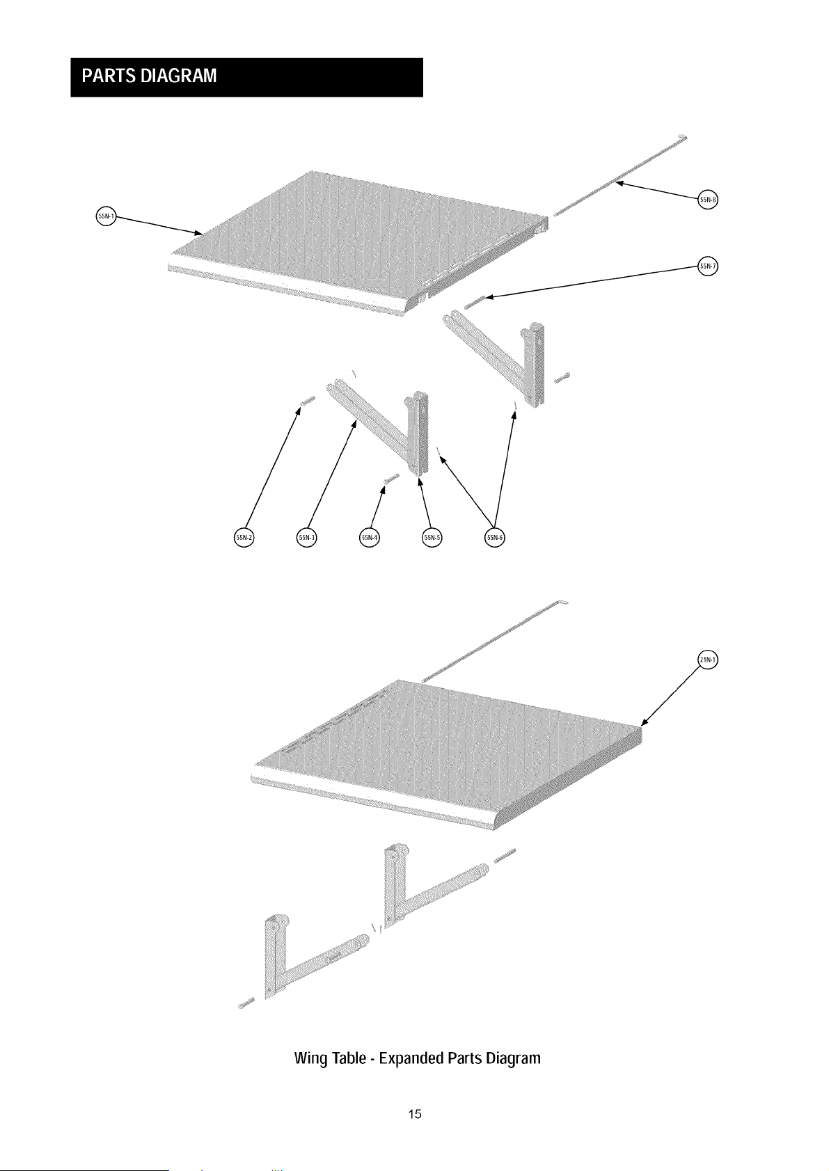
55N 1 LEFTWINGTABLEASSE
55N-1 1 LEFTWINGTABLE
55N-2 2 PIN,37 MM
55N-3 4 SUPPORTBAR
55N-4 4 PIN,43 MM
55N-5 4 VERTICALBAR
55N-6 6 COTTERPIN
55N-7 2 PIN,68 MM
55N-8 2 SHAFT,SIDETABLE
Manufacturer
Part #
2818-2R-7000
2818-2S-7000
2818-2B-1100
3/16-24x3/8in.
2818-2T-1600
SH3118-1803
2818-2T-1102
5/32-32x3/8in.
2818-2T-A600
5/32-32
3218LT-00-8014
5/32-32x3/8in.
2818-2T-1302
2818-2B-1300
2818-2T-1500
2818-2T-1001
2818-2B-3100
M4x8
E3520-00-8015
2818-2B-3003
1/4-20x3/8in.
2818-2B-3001
2818-2R-3001
2818-2S-3001
2818-2B-8300
2818-2T-4000-2
2818-2T-4100-2
6X37
2818-2T-4004
6 X43
2818-2T-4005
1.6X10
2818-2T-4008
2818-2T-4003
If you are missing hardware or have
damaged parts after unpacking grill, call
1-800-482-0131for replacement.
To order replacement parts after using grill,
call 1-800-4-MY-HOME®
13
@
®
_i_!ii_i__i_i!_!iiiii¸¸
_!_!_!!_ii_!!_iiii_i!_!!iii_i!!_iiiiiiiiiiiiiiii_!!iiii!_i!_!!iiiiiiiii_i!!_iiiiiiiiiiiii_iiiiiiiiiiiiiiiiii_!_
iiii_iiiiiiiiiii_iiiii_ii_ii_i_i_iiiii_iiiiiiiiiiiiiiiiiiiiiiiiiiiiiiiiiii_i_i_i_i_i_i_i_ii!i
iiiiiiiii__iiiiii_i_i__iiiiiiiiii_iiiiiiiii___iiiiiiiiiiiii__iiiiiiiiiiii_i_i_i_i!i!i!iiiiiiii_iiiiiiiiiiiiiiiiiiiiii__ii!
®
®
J
J
Wing Table- Expanded Parts Diagram
15

For Model 2818-2B / 2818-2R
For Model 2818-2S
16
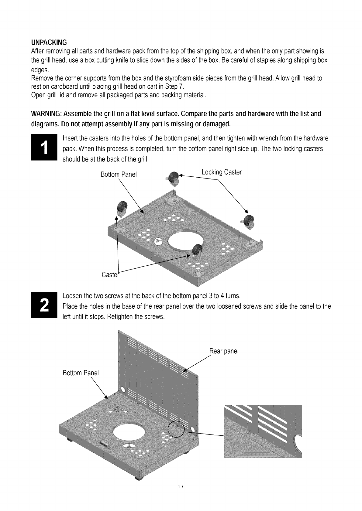
UNPACKING
After removing all parts and hardware pack from the top of the shipping box, and when the only part showing is
the grill head, use a bOXcutting knife to slice down the sides of the box. Be careful of staples along shipping box
edges.
Remove the corner supports from the box and the styrofoam side piecesfrom the grill head.Allow grill head to
rest on cardboard until placinggrill head on cart in Step 7.
Open grill lid and remove all packaged parts and packing material.
WARNING: Assemble the grill on a flat level surface. Compare the parts and hardware with the list and
diagrams. Do not attempt assembly if any part is missing or damaged.
Insert the casters into the holes of the bottom panel, and then tighten with wrench from the hardware
pack. When this process is completed,turn the bottom panel right side up. The two locking casters
should be at the back of the grill.
Bottom Panel Locking Caster
Loosen the two screws at the back of the bottom panel 3 to 4 turns.
Place the holes in the base of the rear panel over the two loosened screws and slide the panel to the
left until it stops. Retighten the screws.
Rear panel
Bottom Panel
It
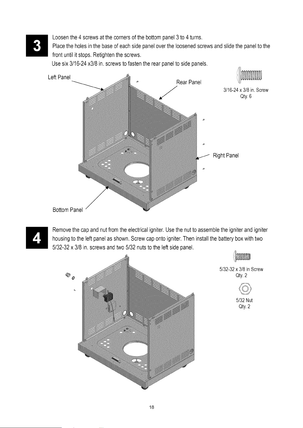
Loosen the 4 screws at the corners of the bottom panel 3 to 4 turns.
Place the holes in the base of each side panel over the loosened screws and slide the panel to the
front until it stops. Retightenthe screws.
Usesix 3/16-24x3/8 in. screws to fasten the rear panel to side panels.
Left Panel
Rear Panel
J
3/16-24x 3/8 in. Screw
Qty.6
Right Panel
Bottom Panel
Remove the cap and nut from the electrical igniter.Use the nut to assemble the igniter and igniter
housing to the left panel as shown. Screw cap onto igniter.Then install the battery box with two
5/32-32 x 3/8 in. screws and two 5/32 nuts to the left side panel.
5/32-32x 3/8 in Screw
Qty.2
5/32 Nut
Qty.2
18
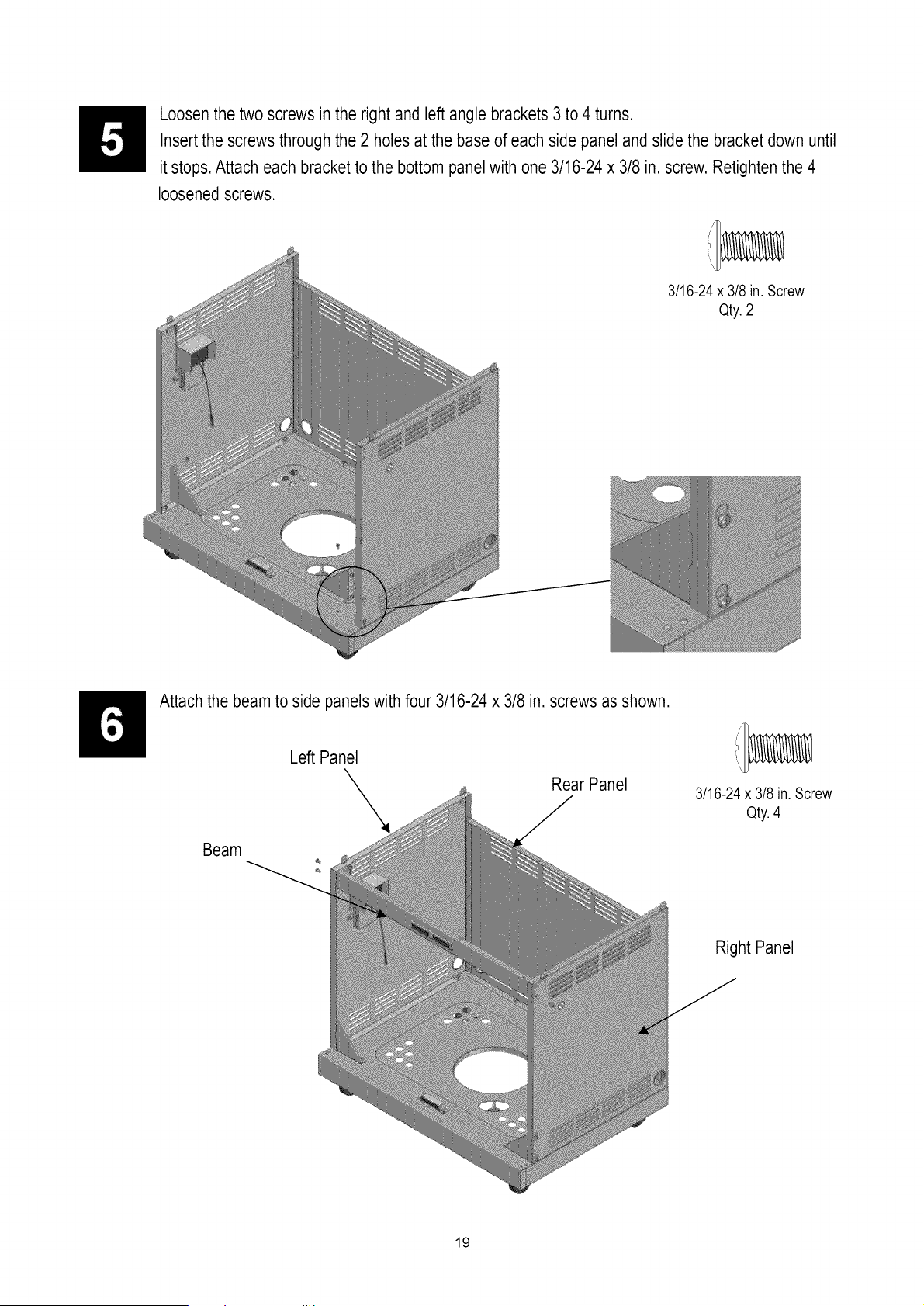
Loosenthe two screws in the right and left angle brackets 3 to 4 turns.
Insert the screws through the 2 holes at the base of each side panel and slide the bracket down until
it stops.Attach each bracket to the bottom panel with one 3/16-24 x 3/8 in. screw. Retightenthe 4
loosened screws.
3/16-24 x 3/8 in. Screw
Qty.2
Attach the beam to side panels with four 3/16-24 x 3/8 in. screws as shown.
Beam
Left Panel
Rear Panel
3/16-24x 3/8 in. Screw
Qty.4
Right Panel
19

Attach the drip tray support to the beam and rear panel with four 3/16-24 x 3/8 in. screws as shown.
Note: Tabs at front attach beneath beam upper ledge.
Left Panel Drip tray support
Rear Panel
3/16-24x 3/8in.Screw
Qty.4
Beam
Right Panel
Grill Head Assembly
First, lockthe two rear casters of the grill cart.
Locate the gas pressure regulator and igniter wires under the grill head control panel. Carefully cut
the tie wrap(s) from the regulator hose. With the aid of an assistant, lift and place the grill head onto
the cart, making sure that the regulator hose and igniter wires hang down into the cart.Align the
corner holes at the base of the grill head with the holes in the corner tabs of the cart. Attach the grill
head to the cart with four 3/16-24 x 3/8 in. screws.
WARNING: Bo not lift grill head from sides. Grasp the grill head by the front control panel and
rear panel to avoid pinching fingers when lowering grill head onto cart.
3/16-24 x 3/8 in. Screw
Qty.4
20

Connect the four burner ignition wires to the four sockets on the right side of the igniter. Connect the
remainingwire to the remaining open socket.
Place the ground wire through the slots on the side panel as shown below. Loosen one control panel
screw, install the ground wire onto the screw, and retighten it to make a good connection.
Install the doors
For each door, insert the bottom hinge pin into the hole in the bottom panel. Push up the top hinge
pin located under the bottom of control panel to get it into the hinge hole in the door. If necessary,
loosen screws on bottom panel magnet housingand adjust and retighten so that doors close
securely.
21
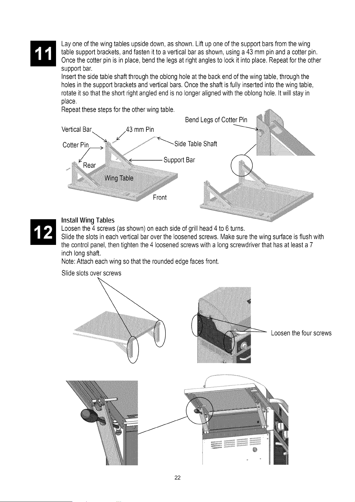
Lay one of the wing tables upside down, as shown. Lift up one of the support bars from the wing
table support brackets, and fasten it to a vertical bar as shown, using a 43 mm pin and a cotter pin.
Once the cotter pin is in place, bend the legs at right angles to lock it into place. Repeat for the other
support bar.
Insert the side table shaft through the oblong hole at the back end of the wing table, through the
holes in the support brackets and vertical bars. Once the shaft is fully inserted into the wing table,
rotate it so that the short right angled end is no longer aligned with the oblong hole. It will stay in
place.
Repeat these steps for the other wing table.
Vertical Bar /43 mm Pin
Cotter Pin
Bend Legs of Cotter Pin
-Side Table Shaft
4' J
......iiiiii!iiiiii!,, , , ,i
Support Bar
Front
Install Wing Tables
Loosen the 4 screws (as shown) on each side of grill head 4 to 6 turns.
Slide the slots in each vertical bar over the loosened screws. Make sure the wing surface is flush with
the control panel, then tighten the 4 loosened screws with a long screwdriver that has at least a 7
inch long shaft.
Note:Attach each wing so that the rounded edge faces front.
Slide slots over screws
Loosenthe four screws
@
22
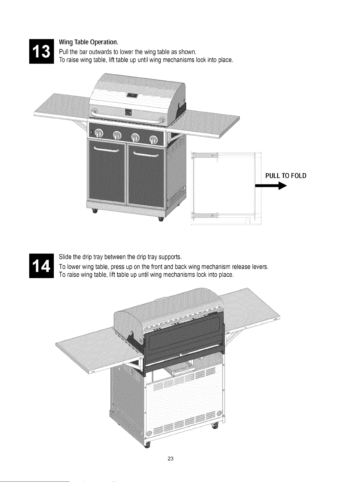
Wing Table Operation.
Pull the bar outwards to lower the wing table as shown.
To raise wing table, lift table up until wing mechanisms lock into place.
PULL TO FOLD
_ IF _
Slide the drip tray between the drip tray supports.
To lower wing table, press up on the front and backwing mechanism release levers.
To raise wing table, lift table up until wing mechanisms lock into place.
23

Position the four heat diffusers, two cooking grids and the warming rack into place.
Note:The diffuser edges fit into slots at front and back of burner box.
Remove battery cap and insert AA battery with positive pole facing out. Replace cap.
Open the battery box and install four AAA batteries into the box with correct polarity.Then couple the
LED light wire with the battery box.
LP Tank Installation
Put the tank into the tank support hole with tank collar opening facing to the right as shown. Connect
the regulator to the tank (see page 5 of Use and Care section).
Lock the tank with the wing-head screw as shown.
Wing-head screw
24

Conversion Instructions for 16154
Main Burner Conversion
,
Remove the R pins at the back of main
burners to detach burners from bracket.
Lift back of main burners while sliding
burners out of firebox, disengaging main
burners from valves. (Fig. 1)
R pin
Back of Firebox
Fig. 1
,
Insert the provided orifice removal tool (B)
into burner openings and unscrew orifices
from ends of valves. (Fig. 2) Orifice
Fig. 2
25
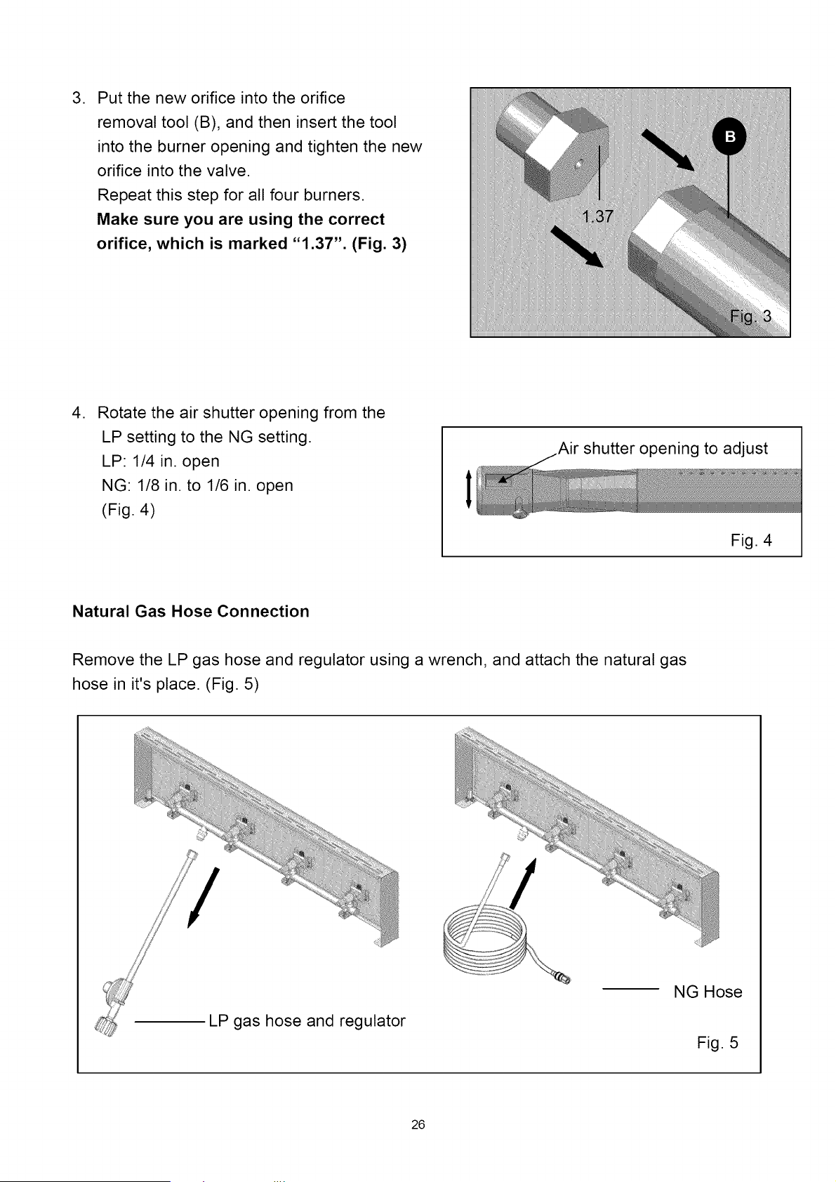
, Put the new orifice into the orifice
removal tool (B), and then insert the tool
into the burner opening and tighten the new
orifice into the valve.
Repeat this step for all four burners.
Make sure you are using the correct
orifice, which is marked "1.37". (Fig. 3)
,
Rotate the air shutter opening from the
LP setting to the NG setting.
LP: 1/4 in. open
NG: 1/8 in. to 1/6 in. open
(Fig. 4)
I
Air shutter opening to adjust
Fig. 4
I
Natural Gas Hose Connection
Remove the LP gas hose and regulator using a wrench, and attach the natural gas
hose in it's place. (Fig. 5)
LP gas hose and regulator
NG Hose
Fig. 5
26

Adjust valve control screw
,
Pull all the knobs off of valve stems. Adjust
the screw in the valve hole using the flathead
screwdriver (C). Turn screws 6 complete turns
counterclockwise.
(Fig. 6)
2. Press all the knobs back onto valve stems.
Valve hole Fig. 6
After all the conversions are complete, return heat diffusers to firebox, followed by the grates
and warming rack.
27
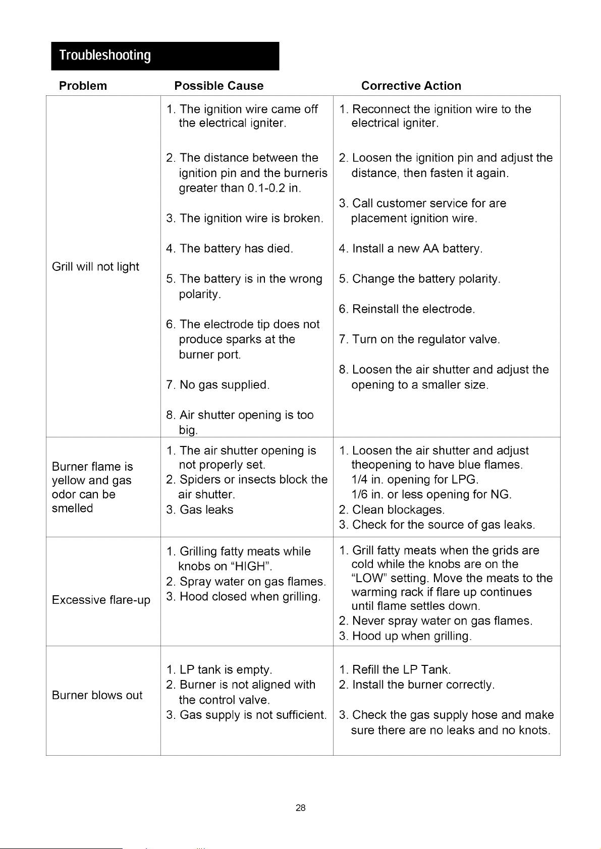
Problem Possible Cause Corrective Action
Grill will not light
Burner flame is
yellow and gas
odor can be
,
2.
smelled 3.
Excessive flare-up
Burner blows out
1. The ignition wire came off
the electrical igniter.
2. The distance between the
ignition pin and the burneris
greater than 0.1-0.2 in.
3. The ignition wire is broken.
4. The battery has died.
5. The battery is in the wrong
polarity.
6. The electrode tip does not
produce sparks at the
burner port.
7. No gas supplied.
8. Air shutter opening is too
big.
The air shutter opening is
not properly set.
Spiders or insects block the
air shutter.
Gas leaks
1. Grilling fatty meats while
knobs on "HIGH".
2. Spray water on gas flames.
3. Hood closed when grilling.
1. LP tank is empty.
2. Burner is not aligned with
the control valve.
3. Gas supply is not sufficient.
1. Reconnect the ignition wire to the
electrical igniter.
2. Loosen the ignition pin and adjust the
distance, then fasten it again.
3. Call customer service for are
placement ignition wire.
4. Install a new AA battery.
5. Change the battery polarity.
6. Reinstall the electrode.
7. Turn on the regulator valve.
8. Loosen the air shutter and adjust the
opening to a smaller size.
1. Loosen the air shutter and adjust
theopening to have blue flames.
1/4 in. opening for LPG.
1/6 in. or less opening for NG.
2. Clean blockages.
3. Check for the source of gas leaks.
1. Grill fatty meats when the grids are
cold while the knobs are on the
"LOW" setting. Move the meats to the
warming rack if flare up continues
until flame settles down.
2. Never spray water on gas flames.
3. Hood up when grilling.
1. Refill the LP Tank.
2. Install the burner correctly.
3. Check the gas supply hose and make
sure there are no leaks and no knots.
28
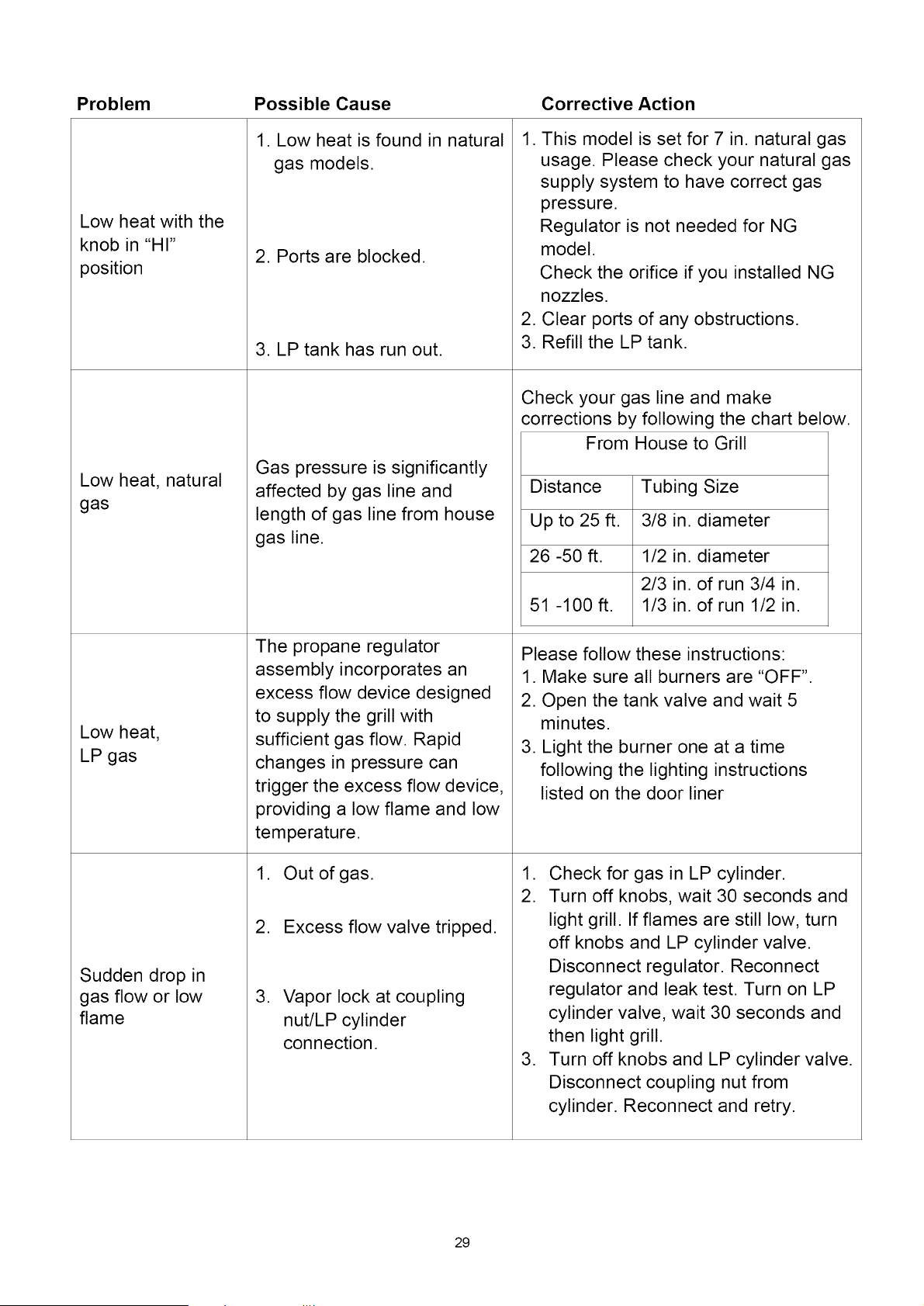
Problem Possible Cause Corrective Action
Low heat with the
knob in "HI"
position
Low heat, natural
gas
Low heat,
LP gas
Sudden drop in
gas flow or low
flame
1. Low heat is found in natural
gas models.
2. Ports are blocked.
3. LP tank has run out.
Gas pressure is significantly
affected by gas line and
length of gas line from house
gas line.
The propane regulator
assembly incorporates an
excess flow device designed
to supply the grill with
sufficient gas flow. Rapid
changes in pressure can
trigger the excess flow device,
providing a low flame and low
temperature.
1. Out of gas.
2. Excess flow valve tripped.
,
Vapor lock at coupling
nut/LP cylinder
connection.
1. This model is set for 7 in. natural gas
usage. Please check your natural gas
supply system to have correct gas
pressure.
Regulator is not needed for NG
model.
Check the orifice if you installed NG
nozzles.
2. Clear ports of any obstructions.
3. Refill the LP tank.
Check your gas line and make
corrections by following the chart below.
From House to Grill
Distance Tubing Size
Up to 25 ft. 3/8 in. diameter
26 -50 ft. 1/2 in. diameter
2/3 in. of run 3/4 in.
51 -100 ft. 1/3 in. of run 1/2 in.
Please follow these instructions:
1. Make sure all burners are "OFF".
2. Open the tank valve and wait 5
minutes.
3. Light the burner one at a time
following the lighting instructions
listed on the door liner
1. Check for gas in LP cylinder.
2. Turn off knobs, wait 30 seconds and
light grill. If flames are still low, turn
off knobs and LP cylinder valve.
Disconnect regulator. Reconnect
regulator and leak test. Turn on LP
cylinder valve, wait 30 seconds and
then light grill.
3. Turn off knobs and LP cylinder valve.
Disconnect coupling nut from
cylinder. Reconnect and retry.
29