Loading ...
Loading ...
Loading ...
4.1 GENERAL SPECIFICATIONS
Display: LCD display
Maximum display: 5999,3-5/6 digits with automatic polarity display and unit display
Measuring method: double integral A / D conversion
Sampling rate: approx. 3 times per second
Over-range display: "OL"
Working environment: 0 ~ 40 °C, relative humidity <80%
Storage environment: -10 ~ 50 °C, relative humidity <80%
Power supply: 1 X 6F22 9V battery
Volume (size): 143mm × 74mm × 35mm (length × width × height)
Weight: about 176g (including battery)
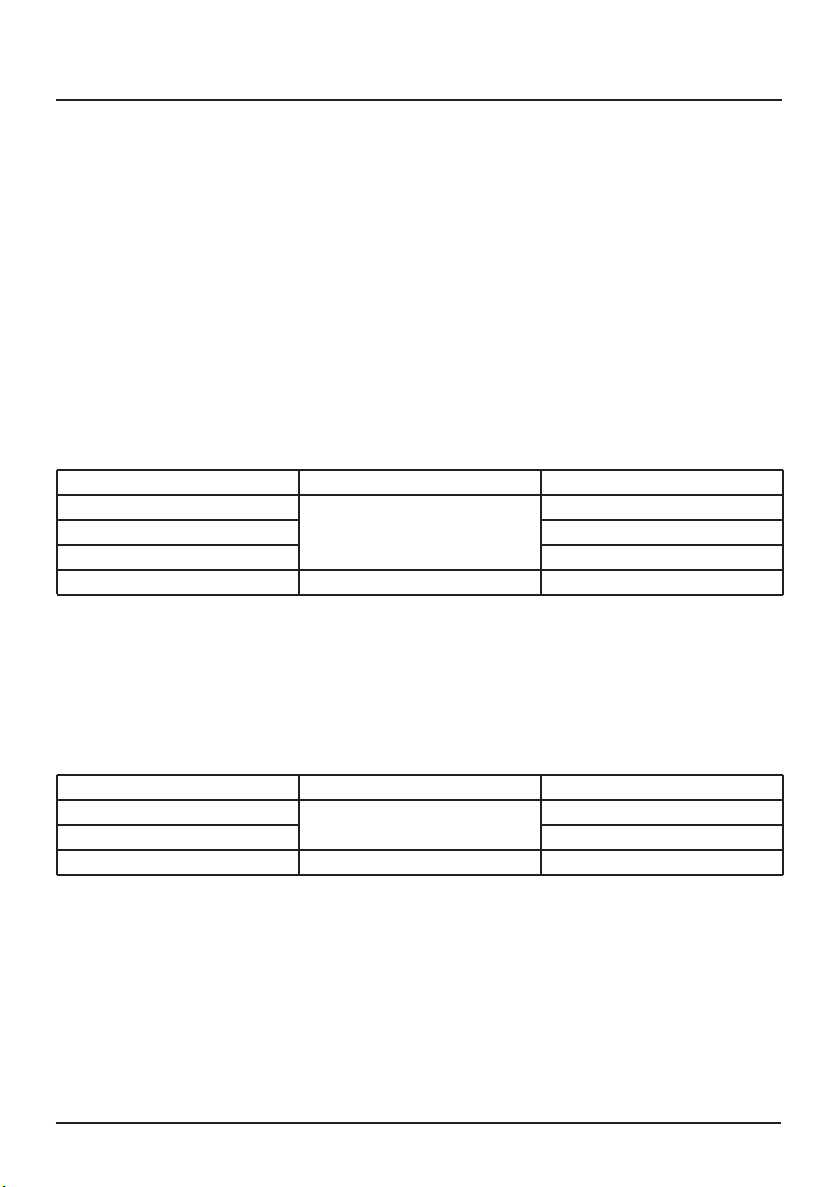
DC Voltage
Range Accuracy Resolution
600mV 0.1mV
6V ±(0.8%+5d) 1mV
60V 10mV
600V ±(1.0%+5d) 100mV
AC Voltage
Range Accuracy Resolution
6V ±(1.2%+5d) 1mV
60V 10mV
600V ±(1.5%+5d) 100mV
Input impedance: 10MΩ.
Overload protection: 600V DC or AC peak.
Frequency response: 40 ~ 1000Hz
Display: Mean response (calibrated to sine wave RMS)
Duty cycle display: (0.1% -99.9%).
Input Impedance: 10MΩ。
Overload protection:600VDC or 750VAC voltage peak value
8.12 CAPACITANCE (C)
1. Turn the measurement function range switch to the capacitor position.
2. Connect the black lead to the com probe socket and the red lead to the 10A probe
socket.
3. Connect the test leads of the test leads in parallel to the measured capacitance, and
the measured capacitance values will be displayed on the display.
Note:
A) When measuring the capacitance, the power must be disconnected in the tested
circuit, and all the capacitors should be fully discharged.
If "OL" is displayed on the display, the measured capacitance value has exceeded
the current range or the capacitor is short-circuited.
B) When measuring large capacitors, it may take a long time, so please be patient. If
the measured 1000uF takes about 1 minute.
C) After completing all measurements, immediately disconnect the test leads from the
circuit under test.
D) Overload protection: 250V DC or AC peak.
Note:
Capacitance below 100PF can not be measured.
8.13 FREQUENCY (HZ%)
1. Turn the measurement function range switch to "Hz%".
2. Press the function key to select Hz or %.
3. Connect the black lead to the com probe socket and the red lead to the 10A probe
socket.
4. Connect the test leads to the source to be measured, and read the results from the
display.
8.14 TEMPERATURE MEASUREMENT
1. Turn the measurement function range switch to the temperature range.
2. Connect the black lead to the com probe socket and the red lead to the 10A probe
socket.
3. Insert the temperature probe into the "COM" and "V " probe sockets, "V ". The sensing
tip of the temperature probe is placed on the surface of the object to be measured.
Note:
A) Read the current measurement from the display.
B) Press "FUNC" to select Fahrenheit, then press "FUNC" to select Celsius.
8. OPERATING INSTRUCTIONS 4. INTRODUCTION
5
16
Loading ...
Loading ...
Loading ...