Loading ...
Loading ...
Loading ...
4.2 HANDLING & STORAGE
Care must still be taken when handling, dropping this machine will have an effect on the
accuracy.
The environment will have a negative result on its operation if you are not careful. If the air
is damp, components will rust. If the machine is unprotected from dust and debris;
components will become clogged.
Temperature sensor: K-type thermocouple (nickel chromium - nickel silicon) Banana probe.
Input Sensitivity: 2.0V.
Overload protection: 250V DC or AC peak.
Duty cycle display: (0.1% -99.9%)
Range Accuracy Resolution
0.1%-99.9% ±(0.5%+3d) 0.1%
Frequency
Range Accuracy Resolution
100Hz 0.1Hz
1000Hz 1Hz
10kHz ±(0.5%+4d) 10Hz
100kHz 100Hz
1MHz 1kHz
10MHz 10kHz
Temperature Measurement
Range Accuracy Resolution
−50°C to300°C ±(1.0%+4d) 1°C
301°C to1000°C ±(1.9%+5d) 1°C
-58°F to600°F ±(1.2%+6d) 1°F
601°F to1832°F ±(1.9%+6d) 1°F
8.1 AUTOMATIC POWER OFF
When the instrument is idle for approx. 15 minutes, the meter will automatically enter a
sleep (shutdown) mode, one minute before actual shut-down the built-in buzzer will sound
five times. To restart the unit, press the FUNC key. To turn the auto power off function off
Press and hold "FUNC" while turning on the meter.
8.2 BUZZER
The buzzer will sound (approx. every 0.25 seconds); when the measured voltage or current
is greater than the maximum allowed range. When the voltage stays over the maximum
range the buzzer will continue to sound as the over-range warning.
8.3 LCD BACKLIGHT DISPLAY
Press and hold the "HOLD" button for more than 2 seconds to turn the backlight display on
and off.
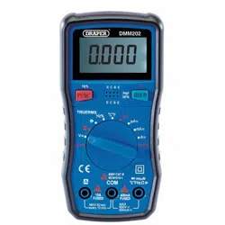
8.4 DC VOLTAGE (DCV)
1. Turn the measurement function range switch to the V≂ voltage range connect the black
lead to the central com probe socket and the red lead to the right hand VΩ probe
socket.
2. Press "FUNC" to select DC voltage on the LCD display.
3. The initial status of the instrument defaults to the auto ranging DC voltage mode, which
displays the "AUTO" symbol.
4. Connect the test leads to the test circuit. The measured voltage will be displayed on the
display.
Note:
A) A voltage higher than DC600V or AC600V cannot be measured and will damage the
meter.
8.5 AC VOLTAGE (ACV)
1. Turn the measurement function range switch to the V≂ voltage range, connect the
black lead to the central com probe socket and the red lead to the right hand V
Ω probe
socket.
2. Press "FUNC" to select the AC voltage range.
3. The initial state of the instrument is auto-ranging and the "AUTO" symbol is displayed.
4. Connect the test leads to the test circuit in parallel to the circuit under test. The polarity
of the red test leads and the measured voltage will be displayed on the display.
Note:
A) A voltage higher than DC600V or AC600V cannot be measured and will damage the
meter.
4. INTRODUCTION 8. OPERATING INSTRUCTIONS
13
8
Loading ...
Loading ...
Loading ...