Loading ...
Loading ...
Loading ...

DC Current
Range Accuracy Resolution
600μA 0.1μA
6000μA ±(1.0%+10d) 1μA
60mA 10μA
600mA 100μA
6A ±(2.0%+10d) 1mA
10A 10mA
Maximum input current: 10A (measurement time is ≤ 15 seconds, interval time is 15
minutes)
Overload protection: 0.4A / 250V resettable fuse 10A / 500V fuse
Open circuit voltage: approx. 2.0V.
Overload protection: 250V DC or AC peak
AC Current
Range Accuracy Resolution
600μA 0.1μA
6000μA ±(1.5%+10d) 1μA
60mA 10μA
600mA 100μA
6A ±(2.5%+15d) 1mA
10A 10mA
Resistance
Range Accuracy Resolution
600Ω ±(1.0%+5d) 0.1Ω
6kΩ 1Ω
60kΩ ±(0.8%+4d) 10Ω
600kΩ 100Ω
6MΩ ±(1.2%+10d) 1kΩ
60MΩ ±(1.8%+15d) 10kΩ
Note:
Maximum input current: 10A (measurement time is ≤ 15 seconds, interval time is 15
minutes)
Overload protection: 0.4A / 250V resettable fuse
10A / 500V fuse
Frequency response: 40 ~ 1000Hz.
Duty cycle display: (0.1% -99.9%)
8.8 RESISTANCE (Ω)
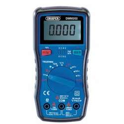
1. Turn the measurement function range switch to the resistance range connect the black
lead to the central com probe socket and the red lead to the right hand V
Ω probe
socket.
2. Connect the test leads in parallel with the measured resistance, measured resistance
will be displayed on the display.
Note:
A) When measuring the resistance, the power supply in the tested circuit must be
turned off, and all the capacitors should be fully discharged.
B) In the measurement of resistance, the appearance of any voltage will cause the
measurement readings are to be incorrect.
8.9 DIODE TEST
1. Turn the measurement function range selection switch to the resistance range.
2. Connect the red lead to the anode of the diode and the black lead to the cathode of the
diode. Read the result from the display.
Note:
A) If the diode is open or the polarity is reversed, "OL" is displayed on the display.
B) When checking the diode, the power supply in the tested circuit must be disconnect-
ed and all the capacitors should be fully discharged.
C) After completing the measurement, immediately disconnect the test leads from the
circuit under test.
8.10 CONTINUITY TEST
1. Turn the measurement function range selection switch to the resistance range.
2. Press the function key to select the continuity buzzer function.
3. If there is continuity in the circuit being tester the buzzer will sound continuously.
8.11 TRANSISTOR HFE TEST
1. Turn the measurement function range selection switch to the hFE.
2. Insert the transistor into the corrisponding holes on the hFE input socket..
3. Read the result from the display.
4. INTRODUCTION
8. OPERATING INSTRUCTIONS
15
6
Loading ...
Loading ...
Loading ...
