Loading ...
Loading ...
Loading ...
11
outdoor equipment and will display SYSTEM MALFUNCTION
on its screen. Refer to the User Interface Installation Instructions
for more detail. See Fig. 14.
G. Generator
The FE fan coil G thermostat terminal input can be configured
through the User Interface to recognize a Generator Normally
Open dry- contact output to signal the system that a generator
malfunction condition exists. Wire the generator output in series
with the R and G thermostat connections at the fan coil control
board. The User Interface will display GENERATOR
MALFUNCTION when the G thermostat input is energized. This
function requires the addition of a Generator Self Test Verifier (Part
No. GSV200) which must be purchased separately. Visit
www.GeneratorVerifier.com for details and ordering information.
Refer to the User Interface Installation Instructions for more detail.
See Fig. 14.
H. Ventilation Accessory
The FE fan coil G thermostat terminal input can be configured
through the User Interface to recognize a Normally Open
dry- contact output to signal the system that a Ventilation
Accessory requires fan coil blower operation. Blower operation can
be configured for Low, Med or High speed when the G terminal is
energized. Wire the Accessory output in series with the R and G
thermostat connections at the fan coil control board. Refer to the
User Interface Installation Instructions for more detail. See Fig. 14.
COMM
OAT
HUM C O Y W G R
CLS
OPN
COM
System
Shutdown
Device
System
Shutdown
Device
or
Generator
or
VentilationAccessor
y
A07121
Fig. 14 - “G” Terminal Accessory Wiring
Procedure 9 — Start- Up and Troubleshooting
NOTE: Always check high and low voltage supply to the fan coil
components. Check the integrity of the plug receptacle connections
and fan coil wiring harness prior to assuming a component failure.
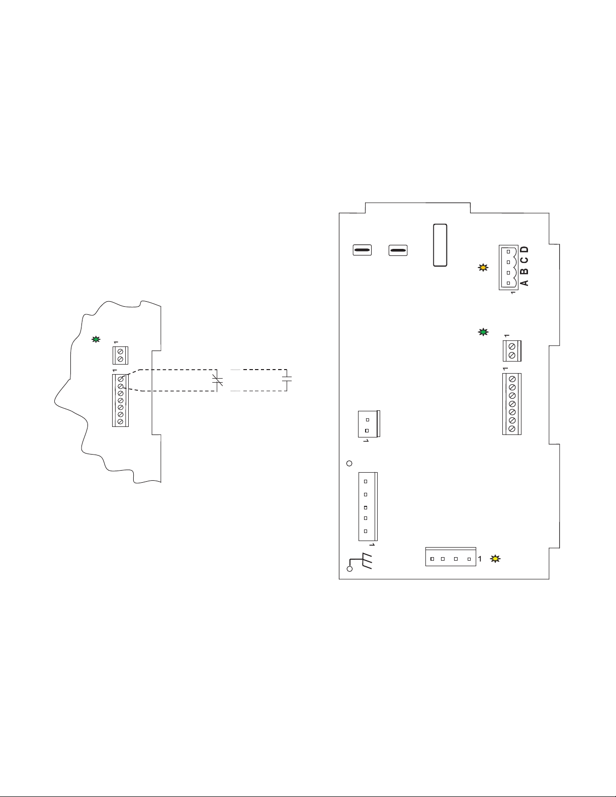
A. LED Description:
LEDs built into fan coil control provide installer or service person
information concerning operation and/or fault condition of the fan
coil control and ECM motor. This information is also available at
system user interface in text with basic troubleshooting
instructions. Careful use of information displayed will reduce the
need for extensive manual troubleshooting.
The amber LED located at bottom center of control adjacent to
motor harness plug is motor status LED and it is labeled MOTOR.
A second amber LED located in upper right center of control
adjacent to System Communications connector (A,B,C,D) is the
System Status LED and it is labeled STATUS. The green LED
labeled COMM is also located adjacent to System
Communications connector, below STATUS LED, and is used as
an indicator of system communications status. Status Codes will be
displayed on the STATUS LED using the following protocol:
1. The number of short flashes indicates first digit of code.
2. The number of long flashes indicates second digit of code.
3. A short flash is 0.25 seconds on. A long flash is 1 second
on.
4. The time between flashes is 0.25 seconds.
5. The time between last short flash and first long flash is 1
second.
6. The LED will be off for 2.5 seconds before repeating code.
SEC-1
SEC-2
FUSE 3AMP
HEATER
STATUS
COMM
OAT
MOTOR
HPT
HUM C O Y W G R
OPN
COM
CLS
A07122
Fig. 15 - Detail of FE4A, FE5A Printed Circuit
Board Connections
B. Fan Coil Control Start- Up and System Communications
Troubleshooting:
On power up, green COMM LED will be turned off until
successful system communications are established (this should
happen within 10 seconds). Once communications with user
interface are successful, COMM LED will be lit and held on. At
the same time, amber STATUS LED will be lit and held
continuously on until a request for operating mode is received. The
STATUS LED will be on any time fan coil is in idle mode. If, at
any time, communications are not successful for a period
exceeding 2 minutes, fan coil control will only allow emergency
heating or cooling operation using a common thermostat, a
Loading ...
Loading ...
Loading ...