Loading ...
Loading ...
Loading ...
10
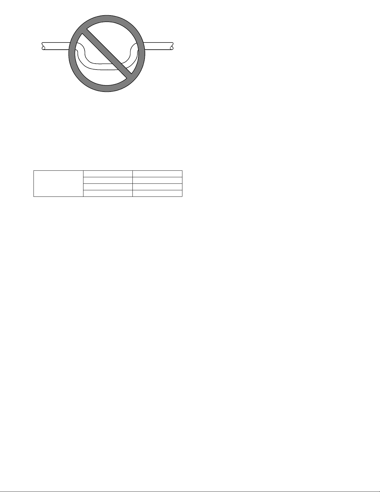
DO NOT USE SHALLOW RUNNING TRAPS!
A03013
Fig. 13 - Insufficient Condensate Trap
IMPORTANT: Factory authorized filters must be used when
locating the filter inside the unit. (See Table 1.) For those
applications where access to an internal filter is impractical, a
field- supplied filter must be installed in return duct system.
Table1–FilterKits
FILT ER KIT
(12 PACK)
PART NUMBER SIZE USED WITH
KFAFK0212MED 002
KFAFK0312LRG 003, 005
KFAFK0412XXL 004, 006
Procedure 7 — Unit Start- Up
Refer to outdoor unit Installation Instructions for system start - up
instructions and refrigerant charging method details.
A. Low - Vo ltage Circuit Fusing and Reference
The low- voltage circuit is fused by a board- mounted 3- amp.
automotive fuse placed in series with transformer SEC1 and R
circuit. The C circuit of transformer circuit is referenced to chassis
ground through a printed circuit run at SEC2 and metal PC board
mounting eyelets. Check to be sure PC Board is mounted securely
using both factory installed screws.
NOTE: Mis- wiring or shorting any of the low voltage
connections may cause the low voltage fuse to open but will not
damage the User Interface or fan coil control. Simply rewire and
replace fuse to correct fault.
Procedure 8 — Accessory Installation
A. Accessory Electric Heaters
Electric heaters may be installed with FE4A, FE5A fan coil per
instructions supplied with electric heater package. See unit rating
plate for factory- approved electric heater kits.
B. Hydronic Heat Applications
The FE fan coil supports 2 types of Hydronic Heat applications:
1. Hot water coil in combination with a heat pump, or hot wa-
ter coil as sole heat source.
2. FE fan coil combined with radiant hot water heat.
In either application, Relay Interface Kit, KFAIF0101HWC, must
be installed in place of an electric heater. The system will identify
that Hydonic Heat has been installed during the initial
commissioning process. The system will treat the hot water coil as
either auxiliary heat in a heat pump application, or as the sole heat
source. Setup options for Hydronic Heat applications are described
in the User Interface Installation Instructions. Options include: Hot
Water Only Operation, Heat Pump Only Operation, Hot Water
Operation during Defrost, Airflow Level Selection, and Blower
ON/OFF Delays.
C. Outdoor Air Thermistor (OAT)
A 2- screw terminal strip is provided for connection of an outdoor
temperature thermistor. This strip is marked OAT. The installation
of an outdoor temperature sensor using the fan coil OAT terminals
is optional. If the outdoor unit is not equipped for communications,
fan coil OAT input can be used to supply outdoor temperature data
for system level functions and for temperature display on User
Interface. Outdoor units with a communicating control are shipped
with a factory installed OAT. This factory installed OAT is used for
all outdoor unit specific and system level functions requiring
outdoor temperature if an OAT is not added to fan coil. If an OAT
is added in the fan coil, the fan coil connected OAT will be used for
system level functions and the factory supplied outdoor unit OAT
will be used for outdoor unit control functions.
Using two wires of field- supplied thermostat wire cable, wire one
lead of thermistor to one screw terminal and the other lead to
remaining screw terminal; there is no polarity to be observed. It is
strongly recommended that two wires be used to connect the
thermistor to eliminate noise interference in temperature reading. If
there are not two spare wires available in cable, one wire may be
used to connect thermistor to OAT screw terminal 1 and the other
lead of the thermistor can be wired to 24VAC COM (C) wire. OAT
screw terminal 1 is terminal located closest to the ABCD system
communications and is marked with a small number 1 next to the
terminal strip.
NOTE: Mis - wiring OAT inputs will not cause damage to either
fan coil control or thermistor. If the thermistor is wired incorrectly,
no reading will appear at User Interface. Re- wire thermistor
correctly for normal operation.
D. Electronic Air Cleaner Connections
When using an electronic air cleaner with FE4A, FE5A fan coil,
use airflow sensor part no. KEAAC0101AAA. The airflow sensor
turns on electronic air cleaner when fan coil blower is operating.
E. Humidifier Connections
The fan coil control terminal marked “HUM” is provided for low
voltage (24VAC) control of a humidifier. No humidistat is required
as User Interface monitors indoor humidity. When commanded to
operate humidifier, the fan coil control will energize the “HUM”
output to turn humidifier on and de- energize HUM output to turn
humidifier off. Wire “HUM” and “C” terminals directly to
humidifier as shown in Fig. 9 or 10.
F. System Shutdown Accessories
The FE fan coil G thermostat terminal input can be configured
through the User Interface to recognize accessories that will shut
the system down in response to a malfunction. Types of devices
may include a Condensate Overflow Switch that is designed for
this purpose. The fan coil can be configured to recognize either
Normally Open or Normally Closed (default) contact devices
through the User Interface Set- Up screens. Wire the accessory
device contacts in series with the R and G thermostat connections
at the fan coil control board. The User Interface will respond to the
accessory device signal by ordering a shutdown of the indoor and
Loading ...
Loading ...
Loading ...