Loading ...
Loading ...
Loading ...
Planning the Wiring
All wire connections and installations must be in
compliance with local codes In the absence of loca!
electrical codes consult the National Electric Code
[]
[]
The (]o_ndraf_ blower system draws 4 AMPS
and requires a 120 VAt!, 60 Hz circuit,
Plan to provide a grom_ded outlet in a
location _dfi(:h will all(m die mlit's p(mer
cord _o reach.
[_] ()n 36'model, )ian tile P_ISEt£OWER s_d_(:h.
• . _Ott
Tile lead _o _he sx_(:h is /= long.
Theoutlet cannot be located on a back wall,
The outlet needs to be momlted on the side _all
of the (abinet or it (ould be on the ba(k _all of an
adjacent (abinet _dth access dlrough an o _ening
in the sk]e wall. (Based on h)(:al (:odes,)
Preparing to Install the Downdraft System
Changing Blower Discharge
The bl()v, er can b e m (mn ted i n tlle ca bi net (,7 u nd er
die floor. The blower will fit between fl()or ioisls on
-t
_6 (:ente_ s.
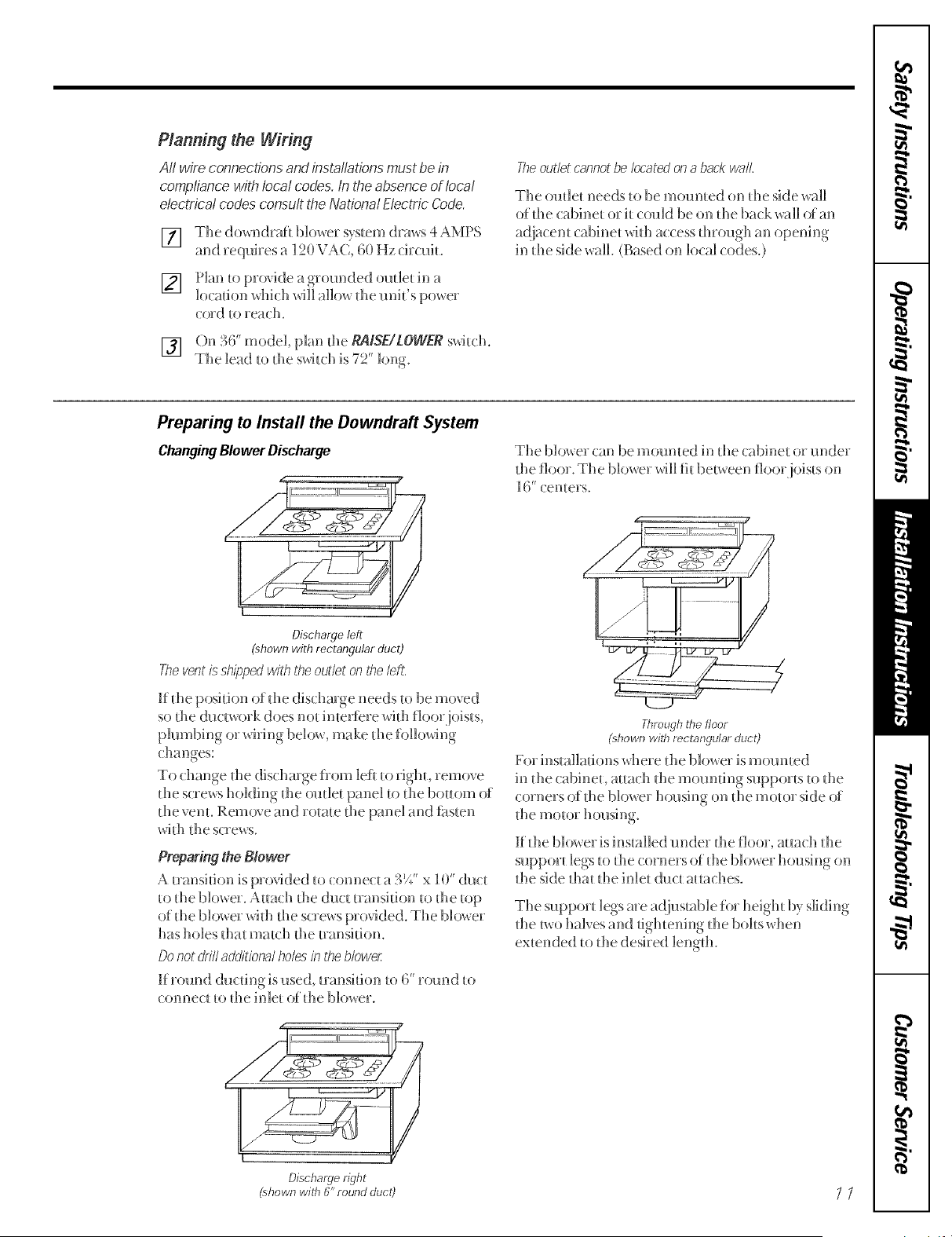
Discharge left
(shown with rectangular duct)
The vent is shipped wfih the outlet on the leR,
If die position of die dischmge needs _o be moved
so the ductwork does not inteHere with floor joists,
plumbing or wMng below, make die following
changes:
To change die dischmge ii()m left _o righh remove
the screws holding die outle_ panel _o die bottom ()i
the venL Remove and rotate the panel and fi_sten
wi_h the screws.
Preparing the Blower
A transition is provided to (onne( t a 3E" x 10" (h]ct
_o die blowe_. A_ach _he (]ud mmsi_ion _o _he _op
of die blower wi_h the screws provided. The blower
has holes dlat ma_(h die _ransifion.
Donot driftadditional holes in the blower
If r(nmd ducfing is used, mmsidon to 6' _Druid to
connect _o_he inle_ of the blower.
/
Throughthefloor
phown with rectangularduct)
For installations where the blower is mourned
in die cabineL a_tach _he moml_ing suppo_ _sto file
corners of die blower housing on die motor side of
_he motor housing
K Ihe blo_x er is installed raider Ihe floor, at_a(:h tlle
suppor_ legs to the corners of die blower housing on
Ihe side dla_ tlle inlet duct a_taches.
The support legs are a(]iusmble for heigh_ by sliding
die _wo halves and tightening die bobs xdlen
ex_ended to tlle desired lengdl.
Discharge right
(shown wiffl (V'round duct) _ /
Loading ...
Loading ...
Loading ...