Part No. t64D3333P024-2 Pub, No, 49-8768-2 D-959-0776-002 7-98 CG
Safety Information
5atetyPrecautions..... 3,4
Operating instructions
Usingthe Downdroft
5_sten ........ 5 o
Usingme 6brttroz_ 5
CJJreand Cleanir_g ..... 6
GE& YOUrA Service Partnership.
Insta#ation lnstl_ctions
Before YouB_ln ....... 7
/_-85ui'et_sn[s 7 9
P/zTningt:heLJuctwod(....... 70
Plan/ngt;helitlirTr_ ..... 77
lnstollin9 toe
[Jowndrafr .... 77 72
sn_//ir1_ the
[7ectrid_7/l}iirmcj....... 73
Troubleshooting Tips
Betor_ 7ou(;_lll
f-orSavlce ..... 74
IMPORTANT!
Fill out and return tile Consumer 1)r(iduct Regism_fion Card that is
pa(ked xdih tllis produ(L Ifvou (annl)l find it, please send in tile
dupli(ate (at(] printed in tile ba(k of this manual.
FORYOURRECORDS
Write the model and serial numbers here:
#
#
Staple sales slip or cancelled check here.
PLEASE NOTE: The downdraft vent systemyou have purchased was
designed to be used with GEProfile cooktops listed in this manual
Proof of tile original purchase date is needed 1(/(/blain ser_i(e under
tile W;lI'I_<ln/y,
Customer Service
ProductReais_ml/on. . . 17
W_Trmnty ..... l_
Service,>ie,pnone
NumbeLs ...... BackCJver
2
READTHISMANUAl_
Inskle you will find many h elpfill hints on how to use and maintain your
vent properly.Just a little preventive care on your pro1 can save you a great
deal of time and money over tile lif> of yore vent.
You H find man) answers to cflmmon problems in die Before YouCafl For
Service secdon. If you re_ex_ our (:harl of Troubleshooting Tips first, you
may not need t11call for service at all.
IF YOUNEEDSERVICE
If you do need seixice, you can relax knox,ing help is only a phone call
away. A list of toll-flee customer sei_ice numbers is included in the back
section 11tthis guide. Or y()u can always call the GE Answer (enter (' at
800.6'26.2000, 24 h(/urs a (1W, 7 (la}:s a week.
IMPORTANTSAFETYINFORMATION.
READALLINSTRUCTIONSBEFOREUSING.
a, WARNING!
For your safety, the information in this manual must be followed to minimize the risk of fire or explosion,
electric shock, or to prevent property damage, personal injury, or loss of life.
WARNING--TO REDUCETHERISKOFFIRE,
ELECTRICSHOCK,ORINJURYTOPERSONS,
OBSERVETHEFOLLOWING:
A. Use this refit only in the manner intended by
the mant/f_tcturer. Ifyou have any questions
(ontact the rnantff_cttHer.
R Befbre servicing or cleaning unit, switch
power offat sewice panel and lock fl_e
service disconnecting means to prevent
power fi_m being switched on accidentally.
\,_l_en the service disconnecting means
cannot be locked, securely fhsten a
pr_)minent wanting device, such as a tag, m
the set_ice panel.
CAUTION: For general ventilating use only.
Do not use to exhaust hazardous or explosive
',, Installation wofl< and electrical wiring must
be done by qualified person(s) in
ac(:o_dan(:e with all applicable codes and
slandmds, including fire-rated (:onstmction.
When cutting or (killing into wall or ceiling,
do not damage electrical wiring and other
hidden utilities.
Dncted f_lns must always be vented to file
outdoors.
S_ttficient air is needed for proper
combustion and exhausting of gases through
the flue (chimney) offilel-burning
equipment to prevent bacl;drafling. Follow
the heating e(pfipment manttthcmrer's
glfideline and safety standards such as those
published by the National Fire Protection
Association (NFI'A), and the American
Society for Heating, Refiigeration and Air
Conditioning Engineers (ASHRAE), and the
local code authorities.
To reduce the risk of fire, use only metal
ductwork.
PVC sewer pipe can be used as duct under
concrete slab if allowed by local code board.
This unit must be grounded.
SAFETYPRECAUTIONS
WARNING--TO REDUCETHE RISK OFA RANGE TOPGREASEFIRE,"
Keep fan, filters and gTease laden
surfaces clean.
:Always turn hood ON when cooking
at high heat.
Use high range settings on range onlywhen
necessary. Heat oil slowly on low to
medium setting.
:i Don't leave range unattended when cooking.
Ahvays use cookware and utensils
appropriate for the type and amount
of food being prepared.
3

IMPORTANTSAFETYINFORMATION
READALL INSTRUCTIONSBEFOREUSING.
A WARNINGf
SAFETYPRECAUTIONS
FIRE,OBSERVETHEFOLLOWING/
TOPERSONS IN THEEVENTOFA RANGE TOP GREASE
A.
SMOTHER FI[AMES with a close-fitting
lid, cookie sheet, or metal tray, then turn
off the burner. BE CAREFUL TO
PREVENT BURNS. If the flames do not go
out immediamly, E%a_CLTATE AND CALL
THE FIRE DEPARTMENT.
B. NEVER PICK UPA FI[AMING PAN--
Y(_u may be burned.
C. DO NOT USE _,%_TER, indudingwet
dishcloths or toweh-a violent steam
explosion will resuh.
D. Use an extinguisher ONLY if:
L Y(m know you h_we a Class ABC
exting_flsher, and you abeady know how u_
operate it.
Z The fire is small and contained in the m>a
where it started.
3. The fire department is being called.
4. You can fight the fire with your back
to an exit,
2%sod on "KitchenF/?esafelyTIps"publishedhy NFPA
CAUTtON: For g_nera] ventilating use onlyo
Do not use to exhaust hazmdous or explosive
Make sure aft fingers are away from the downdraR
top when it is lowered
ff YouNeed Service...
Do not attempt to l_pair or replace any part of
the downdrafi system unless it is specifically
recommended in this gafide. All other secvicing
should be refen_d to a qualified mchnician.
SERVIC/NC
Be sure electrical power is off before servicing the unit,
It may be necessa_ 7 to remove the @)wndrafi
blower system in o_,ter to sewice (omponems
suth as the blower mou)r or air vent
methanism.
Disconnect power to fl_e cooktop and remo_v
it first. Reverse the steps in the Install the
Downdraft set fion to remove the blower.
Sel-vice parts are avaihble from a GE Service
and Parts Center.
Readandfollow this Informationcarefull'
READAND SAVE THESEINSTRUCTIONS
4
Usingthe downdraft system.
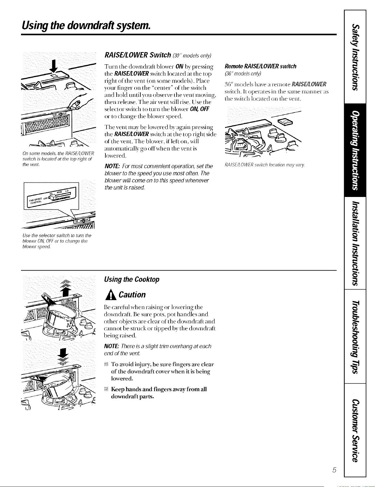
On some models, the RAISE/LOWER
switch is located at the top right of
the vent,
iii ii! i
RAISE/LOWER Switch (3o"models only)
Tmn tile dox_ll(hafi blower ON by pressing
the PAISE/LOWER switch located at the top
right of the vent (oil some models). Place
y{)ur finger oil the "center" of the s_xitch
and hold until you observe the vent rot)ring,
then release. The air vent will rise. Use the
sele(tor s_dtch to mrn tile blower ON, OFF
or to dlange the blower speed.
Tile vent may be lowered by again pressing
the PAISE/LOWERs_a_itchat the top right side
of the vent. The blower, if left on, will
mltomafically go offwhen tile vent is
lowered.
NOTE:Formost convenient operation,set the
blower to the speedyou use most often. The
blower will come onto thisspeed whenever
the unit is raised.
RemoteRAISE/LOIIVERswitch
(36"modelsonly)
36" models have a remote RAISE/LOWER
sx_ch. I_ operates in _t_esame manner as
fl_es_dt(:h lot ated on the vent.
RAISE/LOWERswitch location may vary,
Use the selector switch to turn the
blower ON,OFFor to change the
blower speed,
Using the Cooktop
Caution
Be caretnl when raising or lowering tile
dox_lldrafl. Be sure pots, pot handles and
other objecls are clear of tile do_ll(hafl and
cannot be su_uck or tipped by the dox_lldrafi
being raised.
NOTE"Thereis a slight trim overhangat each
end of the vent.
To avoid h-tj_v, be sure f'mgers are clear
of the dow_draft cover when it is behrig
lowered.
Keep hands and f'mgers away from all
downdraft parts.
Using the downdraft system.
Cooking Tips
The high air m_)vement of this dox_i_drafl
system can increase tile cooking times tot
some fi)ods. It may take longer to reach
high cooking temperatures if the (h_wndrafi
is turned to high right away. A(!just the tim
speed tor best cooking resuhs.
For best resuhs when heating oil fi_r deep
fl)qng or when boiling water, use the fiont
smtace uniLs or wait until the water is
boiling or the oil is at flying temperatures
befi)re turning on the (h)wnchafi.
Thedowndralt may not completelycapture aft the
steam from pans on the front burners,
Catlll_
When canning tbods in a wa/er-bath canner,
a gentle but steady boil nmst be maintained
contimu)usly fi)r the required time.
When canning toods in a pressure canner,
the pressure nmst be re>tint>fined
contimu)usly fi)r the required time,
Use of the blower at HIGHspeed when
canning may reduce the temperature
enough to stop boiling. While canning,
we recommend using the downdmfi at
LOW speed and using the flont surlime unit.
Care and cleaning of the downdraft system.
Grease filters
Theefficiencyofyourdowndmftd_pendson
acban filter
Frequen( 7 of cleaning depends on the tTpe
of cooking you do. Grease fil_ers should be
cleaned at leas[ once a month.
Neverof)eratethe dowrl(2a) withoutthefilter:5
snplace.
Toremove: Lift up and pull _hebo{um_ ore,
Remove d_e left fil_er first, d_en shde d_e
righ_ fil_er u_the lef_ and remo_ e h.
Toclean: Soak and d_en agha_e in a ho_
de_ergem solution. Ligh_ brushing may be
used _o remove imbedded soil. Rinse, shake
and remove moisture before replacing.
Fil_ers may be cleaned by placing in
dishwasher, alfi_ough some sligh_ color
fT_dingmay occur afler several washings.
Whh care_ifi handling, the fiber will lasl for
yems. Ifrepla(emen[ becomes necessary,
order the par{ flom yore dealer.
Painted or metal surfaces
Clean greasysm_ilcesfiequently, using a
miM detergent.
Do not use abrasivecloth or cleaners,steel wool
pads or scouringpowder becausethey will scratch
the surface,

Installationof the downdraft
system. Read meso instructions completely and carefully
WARNING--TO REDUCETHERiSK OFFIRE,ELECTRICSHOCK,ORiNJURY
TOPERSONS,OBSERVETHEFOLLOWING:
A. lns_alla_ior_ work and ele(:_rical wiring mus_ be
done by qualified persons(s) in accord race _d_
all applicable codes and s_andards, inchMing fire-
ra_edcons_rucdon.
B. Ducked f_u_s mus_ always be vetoed _o _he
outdoors.
WARNING--Toreduce the risk of fire, use only metal
ductwork.
Before YouBegin
IMPORTANT: Save t,_eseinstructions for the local
electrical inspector's use.
IMPORTAN_ OBSERVEALL GOVERNING CODES
AND ORDINANCES.
NOTE TOINSTAL£ER:Leave these instructions with
the appliance after installation is completed.
NOTE TOCONSUMER:Keep this Owner's Manual
and installation instructions for future use.
NOTE."This appliance must be properly grounded.
InstallationRequirements
Before starting installation, check the following requirements:
120
4.0
500
3_ " X 10"_
Can be tmnsitioned to round duct (6" round minimum),
This downdrah blo_ er system is designed u) be used
u_ exhaus_ smoke and odors when cooking with aH
(;E Profile electric and gas cooku_ps hs_edh_dfis
manual h (::ar_be mourned in either an island or
Requirements for an approved installation:
26" minimum cabinet depth
_ 26" minimum flora the back of the &)_lldrafi to
the fiont of the countertop, with
23%" mininmm FI AT countertop smthce
:_ Ifyou install the vent and cookt op in an island,
you may need additional island depth. 24" base to
base will not be adequate. Please see below.
Plan the placement of the elecuical outlet carefiflly.
It should NOT be installed on the back wall of the
cabinet be(rauseit may inter{ere with the down&aft.
It should be installed on a side wall or a(!jacent
cabinet. Make sure it is within reach of the unit's 2 ft.
long power cord and conforms to all local codes.
Install a stan&ud outlet to make the electrical
connection.
Plan the locathm of the gas supply pipe (for gas
cooktops) carefiflly to avoid inter[erence with the
downchaft installation.
Thisunit can be easilyinstalledfollowingthese
basicsteps:
[] Cut out the (ountertop opening.
[] Install the (lo_i_(hafl in the cabinet.
[] ( onnect the duclwork and electrical.
[] Install the cooklop.
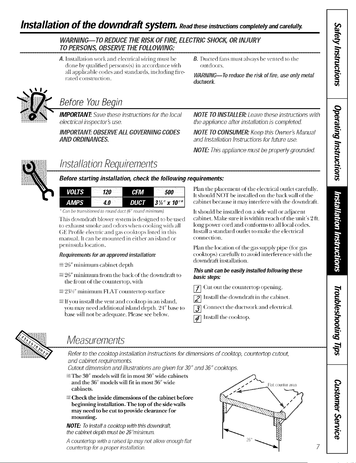
Measurements
Refer to the cooktop installation instructions tot dimensions of cooktop, countertop cutout,
and cabinet requirements.
Cutout dimension and illustrations am given for 30" and 36" cooktops.
_, The 30" models will fit in most 30" wide cabinets
and the 36" models will fit ir_most 35"wide
cablneN.
:_ Check the inside dimensions of the cabinet before
beginning installation. The top of the side walls
may need to be cut to provide clearance for
mounting.
NOTE" Toinstafl a cooktop with this downdraft,
the cabinet depth must be 26"minimum
A countertop with a raised lip may not allow enough flat
countertop for a proper installation,

Installation of the downdrafl system.
Read these instructions completely and carefully.
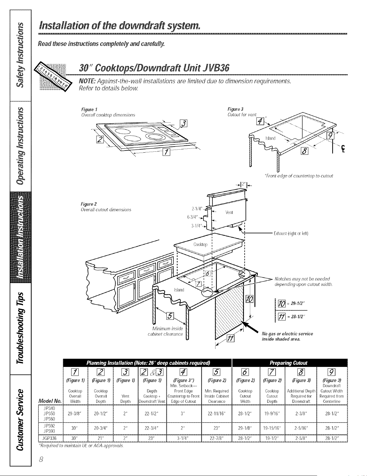
30_!Ceektops/Dewndraft Unit J VB36
NOTE: Against-the-waft instaflations are limited due to dimension requirements.
Reter to details below,
Figure I Figure 3
Overall cooktop dimensions Cutout for vent
Front edge of countertop to cutout
Figure 2
Overall cutout dimensions
Exhaust(rightor left)
Notches may not be needed
depending upon cutout width,
Minimum inside
cabinet clearance
No gas or electric service
inside shaded area,
[] [] [] [] s[] [] []
(Figure 1) (F,(gureI) (Figure I) (Figure I) (Fig_,,re3,_) (Figure 2)
Min,Setback--
Cooktop Cooktop Depth FrontEdge Min,Required
Overall Overall Vent Cooktop+ CounterloptoFront hside Cabinet
ModelNe. Width Depth Depth )owndraRVent Edgeot Cutout Clearance
J P340
JP350 29-3/8" 20-1/2" 2" 22-1/2" 3" 22-11/16"
J P360
J P392 30" 20-3/4" 2" 22-3/4" 2" 23"
J P393
JGP336 30" 21" 2" 23" 3-1/4" 22-7/8"
Required to maintain UL or A6A approvals,
[] [] [] []
(Figure2) (Figure2) CFigure3) (Figure3)
Dewndraft
Cooktop Cooktop AdditionalDepth CutoutWidth
Cutout Cutout Required tot Required from
Width Depth Downdra[t Centerline
28_1/2" 19_9/16" 2-3/8" 28q/2"
29q/8" 19q5/16" 2-5/16" 28q/2"
28q/2" 19-1/2" 2-5/8" 28q/2"

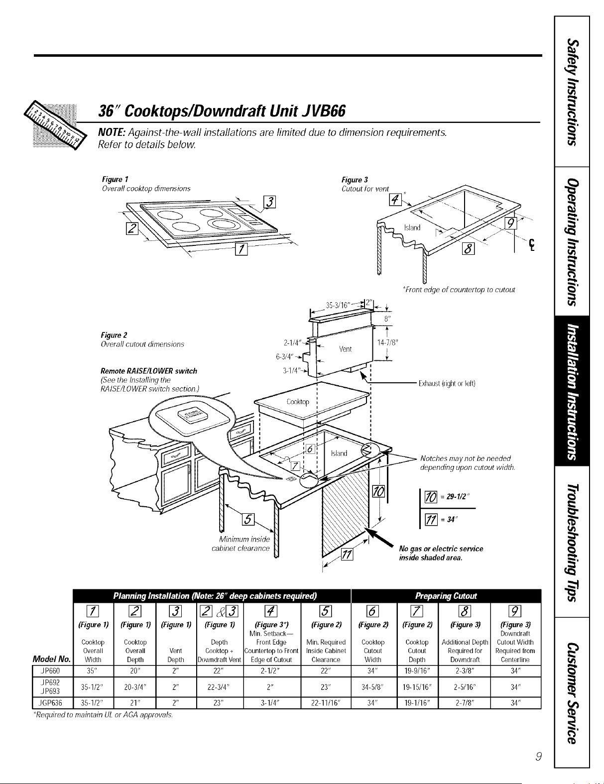
36" Cooktops/Downdraft Unit JVB66
NOTE: Against-the-wall installations are limited due to dimension requirements.
Refer to details below.
Figure I Figure3
Overall cooktop dimensions Cutout for vent
Island
Front edge of countertop to cutout
Figure2
Overall cutout dimensions
RemoteRAISE/LOWERswitch
(See the Installing the
RAISE/LOWERswitch section,)
2-1/4"_
6-3/4"_[_
3-1/4"-_.
Exhaust(rightorleft)
Minimum inside
cabinet clearance
Notches may not be needed
depending upon cutout width,
No gas or electric service
inside shaded area.
[] [] [] [] _[]
(Figure I) (Figure I) (Figure I) (Figure I)
Model No.
JP660
JP692
JP693
JGP636
Cooktop Ceoktop Depth
Overall Overall Vent Ceektop +
Width Depth Depth DewndraRVent
35" 20" 2" 22"
35-1/2" 20-3/4" 2" 22-3/4"
35-1/2" 21" 2"
*Required to maintain UL or AGA approvals.
......... II'11'I'i
[] [] [] [] [] []
(Figure 3*) (Figure2) (Figure2) (Figure 2) (Figure3) (Figure 3)
Min.Setback-- DewndraR
FrontEdge Min.Required Cooktop Ceektop AdditienalDepth CuteutWidth
;ounterteptoFrent InsideCabinet Cutout Cutout Requiredfor Requiredfrom
Edgeof Cuteut Clearance Width Depth Downdraft Centerline
2-1/2" 22" 34" 19-9/16" 2-3/8" 34"
23" 34-5/8" 19-15/16" 2-5/16" 34"
23" 3-1/4" 22-11/16" 34" 19-1/16" 2-7/8" 34"
Installation of the downdrafl system.
Read these instructions completely and carefully.
Planning the Ductwork
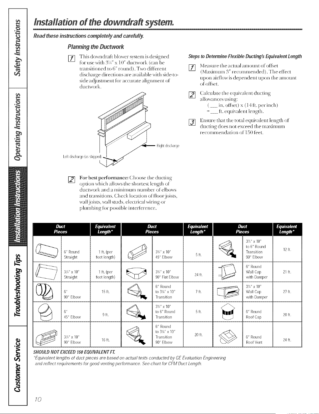
[] This downdrafl Uower system is designed
for use _dfl_ 3/i" x 10" (h_dwork (cm_be
mmsifi(med to 6' _ound). Two diffe_ em
discharge (]i_Te(:tionsave mailable xdd_ sMeqo-
side a({iusmmm _br accurate alignment of
Stepsto DetermineFlexible Ducting's EquivalentLength
] Measme the a(mal amom_t of()f_set
(Maximum 3" re(ommended). The effect
upol_ airflow is dependent upon d_e amomu
of of_get.
[]
[]
Calculate die equivalent duding
allo_%inces using:
( __ h-l.o*_se0 x (14ft. per inch)
=__ tL e(pfi_ alent length.
Ensme diat die total e(lui_ alem lengd_ of
(]u(ting does not ex(eed the maximum
recommendation o_ 150 f>et.
Rightdis/barge
[]
For best perfo_nm'_ee: ( hoose file ducd_lg
option which allows d_e shortest lengfli of
dudwo_ k and a minimum mm_be_ of elbows
and transitions. Check location offiooLjoists,
waffjoists, wall studs, de( tvical _dring ov
plumbing fi, possibD int err>fence.
3X" x 10"
to 6" Round
Transition
90° Elbow
12 ft.
6" Round 1 ft. (per 35" x 10" 5 ft.
Straight foot length) 45° Elbow
0" Round
37F x 10" 1 ft. (per 37F x 10" Wall Cap 21 ft.
Straight foot length) 90° Flat Elbow 24 ft. with Damper
(_ _ 0" Round 35" x 10"
6" 15 ft. to 3Y/' x 10" 7 ft. Wall Cap 27 ft.
90° Elbow Transition with Damper
_ 3W' x 10"
0" to 6" Round 5 ft. 0" Round
45° Elbow 9 ft. Transition Roof Cap 20 ft.
0" Round
to 3Y/' x 10"
374"x 10" Transition 20 ft. 0" Round
90° Elbow 10 ft. 90° Elbow Roof Vent 24 ft.
SHOULDNOT EXCEED150EOU/VALENTFT.
*Equivalent lengths of duct pieces are based on actual tests conducted by GEEvaluation Engineering
and reflect requirements for good venting performance. See chart for CFM Duct Length.
10

Planning the Wiring
All wire connections and installations must be in
compliance with local codes In the absence of loca!
electrical codes consult the National Electric Code
[]
[]
The (]o_ndraf_ blower system draws 4 AMPS
and requires a 120 VAt!, 60 Hz circuit,
Plan to provide a grom_ded outlet in a
location _dfi(:h will all(m die mlit's p(mer
cord _o reach.
[_] ()n 36'model, )ian tile P_ISEt£OWER s_d_(:h.
• . _Ott
Tile lead _o _he sx_(:h is /= long.
Theoutlet cannot be located on a back wall,
The outlet needs to be momlted on the side _all
of the (abinet or it (ould be on the ba(k _all of an
adjacent (abinet _dth access dlrough an o _ening
in the sk]e wall. (Based on h)(:al (:odes,)
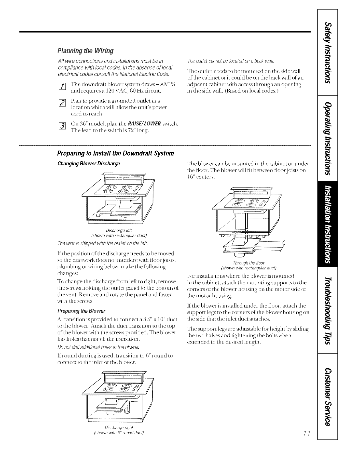
Preparing to Install the Downdraft System
Changing Blower Discharge
The bl()v, er can b e m (mn ted i n tlle ca bi net (,7 u nd er
die floor. The blower will fit between fl()or ioisls on
-t
_6 (:ente_ s.
Discharge left
(shown with rectangular duct)
The vent is shipped wfih the outlet on the leR,
If die position of die dischmge needs _o be moved
so the ductwork does not inteHere with floor joists,
plumbing or wMng below, make die following
changes:
To change die dischmge ii()m left _o righh remove
the screws holding die outle_ panel _o die bottom ()i
the venL Remove and rotate the panel and fi_sten
wi_h the screws.
Preparing the Blower
A transition is provided to (onne( t a 3E" x 10" (h]ct
_o die blowe_. A_ach _he (]ud mmsi_ion _o _he _op
of die blower wi_h the screws provided. The blower
has holes dlat ma_(h die _ransifion.
Donot driftadditional holes in the blower
If r(nmd ducfing is used, mmsidon to 6' _Druid to
connect _o_he inle_ of the blower.
/
Throughthefloor
phown with rectangularduct)
For installations where the blower is mourned
in die cabineL a_tach _he moml_ing suppo_ _sto file
corners of die blower housing on die motor side of
_he motor housing
K Ihe blo_x er is installed raider Ihe floor, at_a(:h tlle
suppor_ legs to the corners of die blower housing on
Ihe side dla_ tlle inlet duct a_taches.
The support legs are a(]iusmble for heigh_ by sliding
die _wo halves and tightening die bobs xdlen
ex_ended to tlle desired lengdl.
Discharge right
(shown wiffl (V'round duct) _ /

Installation of the downdrafl system.
Read these instructions completely and carefully.
Installing the Dewndraft
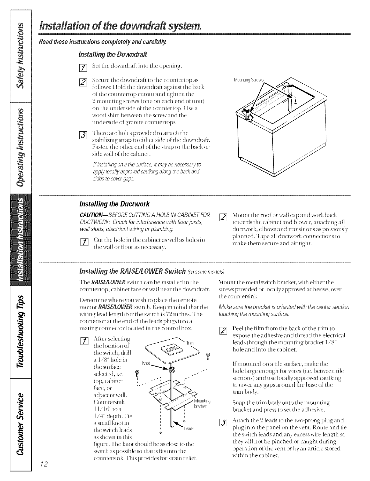
[] Se_ d_e dowr_draf_ imo d_e operfir_g.
] Secure die do_,_ndraf_ _o _he (:()_]]_]_e__op as Mounting%revvs
follow, s: Hold d_e do_ ndrafi agains_ d_e ba(k
of the ( oumertop cutout and tighten the
2 ]{]]()l]n[ii]g scKews (one on erich ef]d ()f!]ni[)
on d_e underside of d_e ('oun_er_op. Use 7_
wood shim between _he soew kind _he
underside of gnmi_e coun_eHops.
[]
Thele me holes p_()_ded _o aHa(::h die
stabilizing-map u) eidler side of tile do_ ndrafi.
Fasten die odle_ end of tile sin@ to tile ba(k or
side wall of die cabinet.
If insta/fing on a tile sur£ace,it may be necess-afyto
app/'/ locally approvedcaulking along the back arid
sides to coverg@s,
Installing the Ductwork
CAUTION--BEFORE CUTTkYGA HOLE IN CABINET FOR
DUCTWORK' @eck for interference with fioo,,joists,
wall studs, electrical wiring or plumbing.
[] Cut die hole in die cabinet as_ell as holes in
tile wall o_ f]oo_ as ne(:essm}.
[]
Mount die roof or _all cap and work back
to_ards tile (abinet and blo_er, mmching all
duc[v_oFk, e]bov, s and t_a_lsJtions as pfevio_as]}
}Janned. Tape aH du(:t_, ork (:onne(:dons to
make them se(:ure and air dgb.
/2
Installing the RAISEtL OWER Switch Ig_somemodels)
The RAiSE/LOWER swit dl can be installed in tile
(:ounter_op, (abinet fh(:e or wail near tile do_ n(kafl.
Detem_ine where you t_4sh to place tile remote
mount RAISE/LOWER switch, Keep in mind t]lat the
wiring lead ]engdl for die switch is 72 inches. The
connector at die end of die leads plugs into a
madng ( onnector loomed h-_the ( omro] box.
[]
Aft e_ se]ecdng
the ]ocadon of
the _witc]< dd]]
_ ]/8" hole in
the smii_ce
sele(ted_ i.e.
Countersink
] ]/]6"toa
a small knot in
tile switch leads
as shown in this
figure. The knot shouk] be as (:lose U) tile
s_,@th as possible so flint is fits imo tile
(:ountersink. This provides fi)r suain relief.
Mount tile mem] switch bracket, _it]l eidler the
s(:re_ s provided or locally approved adhesi,,e, over
the countersink.
Make surethe bracket is orientedwith the center section
touchingthemountingsurbce.
[]
Peel tile film flom tile ba(:k of tile trim to
expose die adhesi,,e and dlread die e]e(:uica]
leads dlrou£h tile moundng b_ a(:ket ]/8'
hole and into tlle cabinet.
Kmounted on a tilesm_hce,make the
hole ]mge enough for wi_es (i.e. between die
se(:dons) and use locally approved cm_]king
to cover any gaps m'ound the base ()f the
[]
Snap tile Uim body onto tile mounting
bracket and press to set die adhesive.
Attach die 2 leads to tile two-prong }Jug and
p]u_int()the pan e]on tile_ent.R()_]te and tie
tile s_4t(;]l leads and any excess wi_e ]en_lh so
die,, wi]] not be phlched or caught dmin_
operadon of tile vent o_"b) an mdc]e sto_ed
_4dlin tile cabinet.
Installing the Electrical Wiring
[] MomH a s_anda_d wiring box, wi_h _-p_onged,
120 vdL 60HZ omieL insk]e d_e (abine_
Make sme the downdrafl'g power cord can
[]
[]
Rm_ fl_e appropriate po_ er cable imo fl_e
cabinet an(] (:()nnect it t() the o!]t]et.
Plug tile downdrafl's power cord into tile
omiet.
For tocM Insta#ation
Theconduit orl the blo_xer/3-of suFicierlt /erlgth to connectto
the downdf_fl when the blower is mounted in the cabinet and
for some/rlstallst/ons urlder the floor
Plug die blowe5 conduit into die mating connector
on the bottom of wising con_pmtment covey on the
down(karl, ffasten the vds:ebox to the main refit
wiring comp>wmlem _dth die screws pro@led.
For Remote Installations
If the blower conduit is not long enoughto reach the wiHr_q
compar_Tnentorl the dowrldr_lfi,the leads carl be extendet_
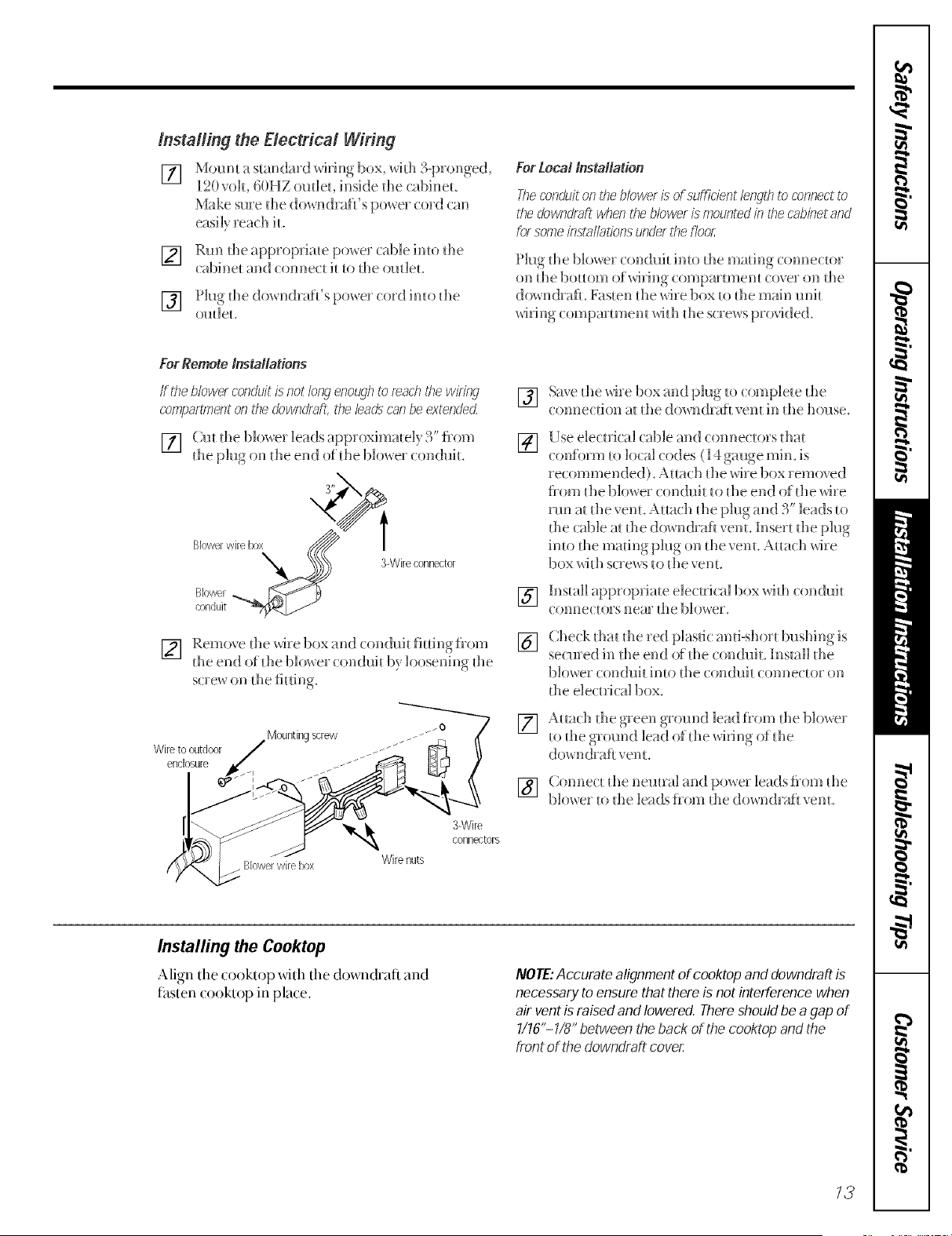
[] Cm the b]o_er lea(Is ap[)roximate]y 3" fl:om
tile plug on tile end of the b]o_ er 5:on(]uit.
I:)oX,4, _))_x _ 3-Wireconnector
Blowerwife
Blower_ _
{ onduit
[] Remove tile wis:e box and conduit fitfingflom
tile end of tile blo_ es conduit b} loosening tile
screw on tile fitting.
Mountingscrew ___ __o
Wire to outdoor / _J J
enclosure ,__ J jJ
"_ 3-Wire
connectors
Blowerwire box Wirenuts
[]
[]
[]
[]
[]
Saxe the wive box and plug to complete tile
5:onne(fion at the (]own(]_aft vent in the ]louse.
Use electsk:al (able _m(] conne(toFs that
(:onfom_ to local codes ( 14 gmlge rain. is
recommended), Att_wh tile wise box removed
flom die blower conduit to die end of the wis:e
rml at the venL Attach the plug an(] 3" ]ends to
the cable at the (]own(kn_ vent. Insert die plug
into the nlatin_ pbl_ on the re]lit, Attach wile
box _lt]l scsews to the vent.
Install appropriate eles:tvic_d box sddl conduit
C ( 5 55n e c{ o5"s 55 e f!5" t ]le 1) ] (5we 5",
Ches:k fllat tile 5ed plastic anti-short bushing is
ses:med in file end 5)_tile con(brit. ]install the
1)]o_es csm(]uh into the con(]uit 5:onnectsn on
die eles:{fis:al box.
Att_ch the gseen gsomld lead flom tile blower
to tile groined lead of tile _dfing of tile
(]()wn (]faf_ vent.
[] Connes:t die neutral and })55wetleads flom die
blower t55the leads fl55m the (](5_n(]r:4ft _ent.
Installing the Cooktop
Align the (ooktop with the down(karl and
fhsten ( ooktop in pla(e.
NOTE:Accurate alignment of cooktop and downdraft is
necessary to ensure that there is not interference when
air vent is raised and lowered. There should be a gap of
1/16"- 1/8" between the back of the cooktop and the
front of the downdraf_ cover
/3

Before YouCarl For Service...
Troubleshooting tip
Save time and money'! Review the tip below and you may"
not need to call tot service,
Possible Causes What ToDo
Fan does not work
The vent ls not fulIyextendedo * hessd_egAISE/LOWEg s_dl(:h.
The blower control switch may * Shde h to d_e figh_.
be in the OFF position°
14
Notes
m
w
w
m
m
_a
m
to
/g

m_
Notes
1C

GE Service Protection Plus TM
GE, a name recognized worldwide for qualib_ and dependabilib_, offbrs you Se_ice
Protection Plus'-comprehensive protection on all your appliances-No Matter
What Brand!
Benefits Include:
*Backed by GE
°All brands covered
oUnlimited service calls
oAll parts and labor costs included
° No outoofopocket expenses
° No hidden deductibles
° One 800 number to call
We'll Cover Any Appliatlce.
Anywhere. Anydme. *
You will be completely satisfied _d_h our senice pro_ecdon or )ou may reques_ your mone) back
on [l_e remaining value ofyour comracu No questions asked, h's d_a_ simple.
Protect your refiigerator, dishwasher, washer and dryer, range, TV, V(R and mu(h more-any brand!
1 lus d_ere.......s no exua (haroe_.....for emeroencv_. sen,ice and lo_ momhly fir_ancing is a_ailable. E_en icemaker
coverage and food spoilage pro_ecfion is offered. You can res_ easy knowing d_a_ all your valuable
household produc_s are pro_ec_ed agains_ expensive repairs.
Pl'._e,,,., _:,,._deme i. (;E a.d _all._ i. _heU.S..,ll-hee a_800-62(b2224
for more hfforma_ion,
I'\]] brmds (:ovel ed, up to 20 yetrs old, in file ( OllIilleIll}I] [[ ,S.
_(:ul h(q()
Please place in envelope and mail to:
General Electric Company
Warranty Registration Department
P.O. Box 34070
Louisville, KY 402324070
17

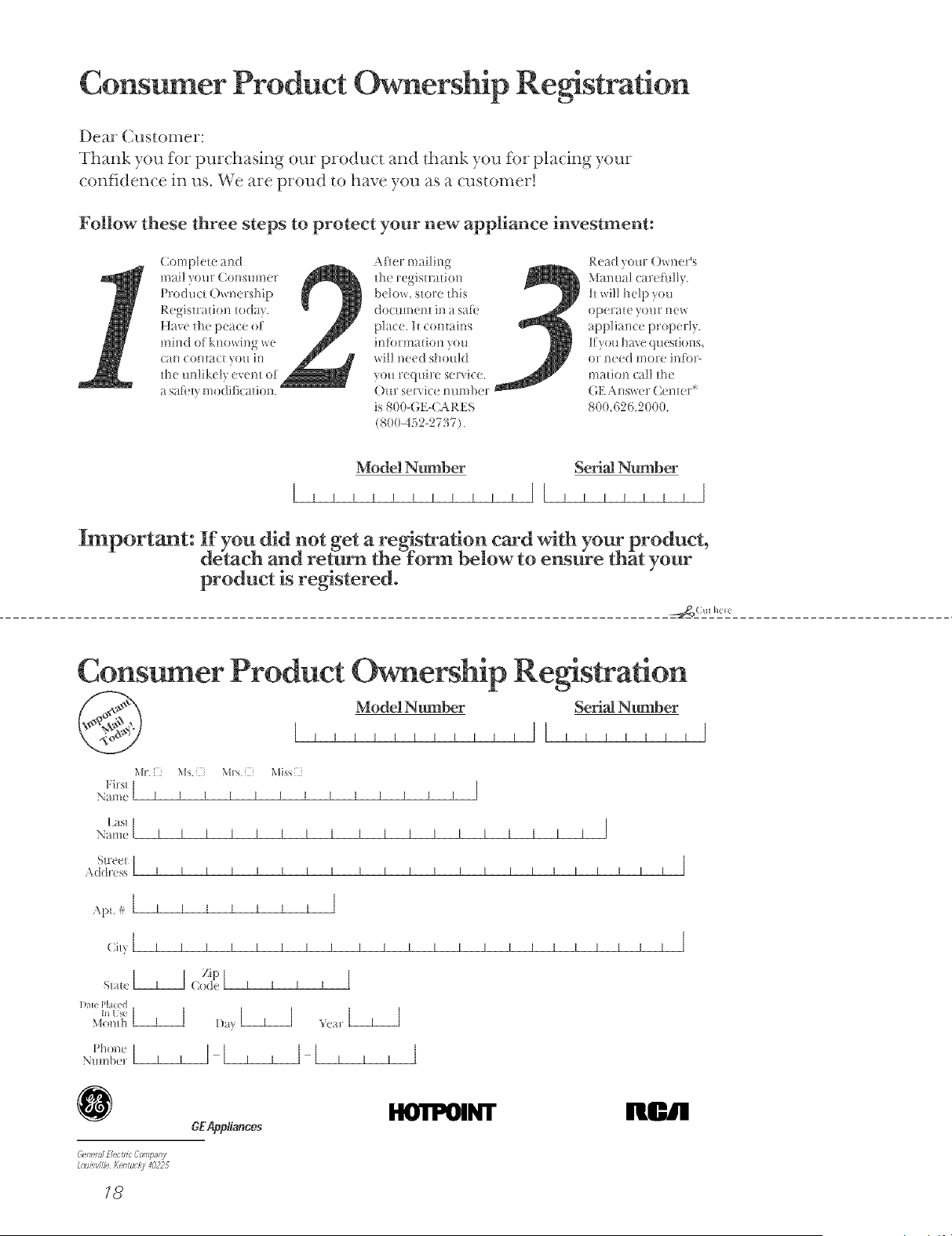
Consumer Product Ownership Registration
Dear Customer:
Thank you for purchasing our produc_ and _hank you %r placing your
c(mf]dence in us. \_;e are proud to have y(m as a custoi_er!
Follow these three steps to protect your new appliance investment:
( ompiele and
mail yore (:onsm_er
Product Own( rship
Rt)gis!l 3iiol] loday.
Have lho peace of
mind of knowing we
(ill] COI]_IC[ yOll ill
lhe m_likely evem of
a safflv modificalion.
Ariel" mailing
Ill( regisiralion
below, store fills
(]OC!l!lleI!l ill 3 Sa_[
place. 11_(Olll_ills
inf?)rmaiion you
wil! need should
yoll re(itlire s(ixice.
()ur se_ ic( mmfl)ei
is 800-GE4;ARES
(8(/0-452-2737).
Read your Owner's
Manual carefi_lly.
it will help you
operale }O!lr new
applian(e properly.
Kyou h_ c questions,
or need more illf_)l'-
Ill31iOll (all lhe
(;E Answer Cemer
800.626.2000.
Model Number Serial Number
Important: If you did not get a re_stradon card with your product,
ddtach and reffurn the-form below to ensdre thgt your
product is registered.
Consumer Product Ownership Reg
Model Number SeriN Number
Mr. MS. Miss
l;irsl [
Nam( I I I I I I I I I I I I I [
L_S1 [Nam_ [ [ [ [ [ [ [ [ [ [ [ [ [ [ [ [ [ [ [
Addr(ss [ [ [ [ [ [ [ [ [ [ [ [ [ [ [ [ [ [ [ [ [ [
Api. # I I I I I
(:i,?[llllllll IIIIII I I I I I I I I [
S/_tt_. [_ Zip( _K ( I I I I [
] );l[( P[ I((d
N!lmb_t_
GeneralE/ectnc CornparO_
Loul:_vd/eKentucky 40225
/8
GEApp/iancos
BR)'[POINT RCIBI
GEDowndraft System Warranty
All warranty service provided by our Factory" Service Centers,
or an authorized Customer Care_) technician. For service,
carl 800-GE-CARES.
One Year
Fromthe date of the
originalpurchase
GE Will Replace, At No Charge To You:
Anypart of the d_)wn&afi sFslem which f, fils due to a deiect in materials or w_)rkmanship.
During this full one-year warranty, GE will also provide, free of charge, all labor
and in-home sevvice to replace the detective part.
:_ Service trips to your home to teach you how to use the
product.
:_ Improper installation.
:_ Failure of the product if it is abused, misused, or used for
other than the intended purpose or used commercially.
:_ Replacement of house fuses or resetting of circuit
breakers.
:{ Replacement of the replaceable filters.
:, Damage to the product caused by accident, fire, floods or
acts of God.
:, Incidental or consequential damage to personal property
caused by possible defects with this appliance.
This warranty is extended to the original purchaser and any succeeding owner for products purchased for home
use within the USA. In Alaska, the warranty excludes the cost of shipping or service calls to your home.
Some states do not allow the exclusion or limitation of incidental or consequential damages. This warranty gives
you specific legal rights, and you may also have other rights which vary from state to state. To know what your
legal rights are, consult your local or state consumer affairs office or your state's Attorney General.
Ifyou have an installation problem, contact your dealer or installer. Youare responsible for providing adequate
electrical, gas, exhausting and other connecting facilities as described in the Installation Instructions provided
with the product.
Warrantor:General Electric Company.Louisville,KY 40225
19
Service TelephoneNumbers.
CEAnswer CenteF_soo._2_.2ooo
The (,E Answe_ (eme_ is open 24 hou_ s a day 7 days a week.
/n-HomeRepsi; ServiceSOOoCE-CARES(800-432-2737)
SpecialNeedsServiceso#._2_.2_o
800- TDD-GEAC (800-833°4322)
(;E offers, fiee of ( barge, a bye( huve _o assis_ in planning a bavviev-fiee ki_( hen fov persons
wilh limited mobiiib,.
ServiceCent;actssee-szs-zzz4
subs[ands] dis(:ounL (;E Consumer Service will sdH be there after )out wavTanty expi;es.
PartsandAccessoriessoooszs-zeez
h_di_iduals qualified to se_xice d_ei_7own appliances can have pmts o_7a( cessories seflt di_Tecdy
to d_eh: homes (VISA, MasterCmd and Discover7 cm'ds me accepted).
Instructions contained in this manual cover procedures to be.performed by any user. Other servicimj
generally should be referred to qualified service personnel Caution must be exercised, since
improper servicing may cause unsafe operation.
ServiceSatisfaction
I_}:ou me not s_tisfied with the se_x:ice you ;e( eive fiom GE:
First,(ontad d_e people who sevviced your appliance.
Next,if you ave sdll not please(], write all d_e details--including your phone numbe;-to:
Manager, Consumer Relations
GE Appliances
Louisville, KY 40225
Finally,if your probDm is sdll not resoDed, write:
M_jor Appliance Consumer Acdon Pvogrm_
20 No_lh Wacke_ Drive
20 Printed in file United States

Part No. t64D3333P024-2 Pub, No, 49-8768-2 D-959-0776-002 7-98 CG
Safety Information
5atetyPrecautions..... 3,4
Operating instructions
Usingthe Downdroft
5_sten ........ 5 o
Usingme 6brttroz_ 5
CJJreand Cleanir_g ..... 6
GE& YOUrA Service Partnership.
Insta#ation lnstl_ctions
Before YouB_ln ....... 7
/_-85ui'et_sn[s 7 9
P/zTningt:heLJuctwod(....... 70
Plan/ngt;helitlirTr_ ..... 77
lnstollin9 toe
[Jowndrafr .... 77 72
sn_//ir1_ the
[7ectrid_7/l}iirmcj....... 73
Troubleshooting Tips
Betor_ 7ou(;_lll
f-orSavlce ..... 74
IMPORTANT!
Fill out and return tile Consumer 1)r(iduct Regism_fion Card that is
pa(ked xdih tllis produ(L Ifvou (annl)l find it, please send in tile
dupli(ate (at(] printed in tile ba(k of this manual.
FORYOURRECORDS
Write the model and serial numbers here:
#
#
Staple sales slip or cancelled check here.
PLEASE NOTE: The downdraft vent systemyou have purchased was
designed to be used with GEProfile cooktops listed in this manual
Proof of tile original purchase date is needed 1(/(/blain ser_i(e under
tile W;lI'I_<ln/y,
Customer Service
ProductReais_ml/on. . . 17
W_Trmnty ..... l_
Service,>ie,pnone
NumbeLs ...... BackCJver
2
READTHISMANUAl_
Inskle you will find many h elpfill hints on how to use and maintain your
vent properly.Just a little preventive care on your pro1 can save you a great
deal of time and money over tile lif> of yore vent.
You H find man) answers to cflmmon problems in die Before YouCafl For
Service secdon. If you re_ex_ our (:harl of Troubleshooting Tips first, you
may not need t11 call for service at all.
IF YOUNEEDSERVICE
If you do need seixice, you can relax knox,ing help is only a phone call
away. A list of toll-flee customer sei_ice numbers is included in the back
section 11tthis guide. Or y()u can always call the GE Answer (enter (' at
800.6'26.2000, 24 h(/urs a (1W, 7 (la}:s a week.

IMPORTANTSAFETYINFORMATION.
READALLINSTRUCTIONSBEFOREUSING.
a, WARNING!
For your safety, the information in this manual must be followed to minimize the risk of fire or explosion,
electric shock, or to prevent property damage, personal injury, or loss of life.
WARNING--TO REDUCETHERISKOFFIRE,
ELECTRICSHOCK,ORINJURYTOPERSONS,
OBSERVETHEFOLLOWING:
A. Use this refit only in the manner intended by
the mant/f_tcturer. Ifyou have any questions
(ontact the rnantff_cttHer.
R Befbre servicing or cleaning unit, switch
power offat sewice panel and lock fl_e
service disconnecting means to prevent
power fi_m being switched on accidentally.
\,_l_en the service disconnecting means
cannot be locked, securely fhsten a
pr_)minent wanting device, such as a tag, m
the set_ice panel.
CAUTION: For general ventilating use only.
Do not use to exhaust hazardous or explosive
',, Installation wofl< and electrical wiring must
be done by qualified person(s) in
ac(:o_dan(:e with all applicable codes and
slandmds, including fire-rated (:onstmction.
When cutting or (killing into wall or ceiling,
do not damage electrical wiring and other
hidden utilities.
Dncted f_lns must always be vented to file
outdoors.
S_ttficient air is needed for proper
combustion and exhausting of gases through
the flue (chimney) offilel-burning
equipment to prevent bacl;drafling. Follow
the heating e(pfipment manttthcmrer's
glfideline and safety standards such as those
published by the National Fire Protection
Association (NFI'A), and the American
Society for Heating, Refiigeration and Air
Conditioning Engineers (ASHRAE), and the
local code authorities.
To reduce the risk of fire, use only metal
ductwork.
PVC sewer pipe can be used as duct under
concrete slab if allowed by local code board.
This unit must be grounded.
SAFETYPRECAUTIONS
WARNING--TO REDUCETHE RISK OFA RANGE TOPGREASEFIRE,"
Keep fan, filters and gTease laden
surfaces clean.
:Always turn hood ON when cooking
at high heat.
Use high range settings on range onlywhen
necessary. Heat oil slowly on low to
medium setting.
:i Don't leave range unattended when cooking.
Ahvays use cookware and utensils
appropriate for the type and amount
of food being prepared.
3
IMPORTANTSAFETYINFORMATION
READALL INSTRUCTIONSBEFOREUSING.
A WARNINGf
SAFETYPRECAUTIONS
FIRE,OBSERVETHEFOLLOWING/
TOPERSONS IN THEEVENTOFA RANGE TOP GREASE
A.
SMOTHER FI[AMES with a close-fitting
lid, cookie sheet, or metal tray, then turn
off the burner. BE CAREFUL TO
PREVENT BURNS. If the flames do not go
out immediamly, E%a_CLTATE AND CALL
THE FIRE DEPARTMENT.
B. NEVER PICK UPA FI[AMING PAN--
Y(_u m ay be burned.
C. DO NOT USE _,%_TER, indudingwet
dishcloths or toweh-a violent steam
explosion will resuh.
D. Use an extinguisher ONLY if:
L Y(m know you h_we a Class ABC
exting_flsher, and you abeady know how u_
operate it.
Z The fire is small and contained in the m>a
where it started.
3. The fire department is being called.
4. You can fight the fire with your back
to an exit,
2%sod on "KitchenF/?esafelyTIps"publishedhy NFPA
CAUTtON: For g_nera] ventilating use onlyo
Do not use to exhaust hazmdous or explosive
Make sure aft fingers are away from the downdraR
top when it is lowered
ff YouNeed Service...
Do not attempt to l_pair or replace any part of
the downdrafi system unless it is specifically
recommended in this gafide. All other secvicing
should be refen_d to a qualified mchnician.
SERVIC/NC
Be sure electrical power is off before servicing the unit,
It may be necessa_ 7 to remove the @)wndrafi
blower system in o_,ter to sewice (omponems
suth as the blower mou)r or air vent
methanism.
Disconnect power to fl_e cooktop and remo_v
it first. Reverse the steps in the Install the
Downdraft set fion to remove the blower.
Sel-vice parts are avaihble from a GE Service
and Parts Center.
Readandfollow this Informationcarefull'
READAND SAVE THESEINSTRUCTIONS
4

Usingthe downdraft system.
On some models, the RAISE/LOWER
switch is located at the top right of
the vent,
iii ii! i
RAISE/LOWER Switch (3o"models only)
Tmn tile dox_ll(hafi blower ON by pressing
the PAISE/LOWER switch located at the top
right of the vent (oil some models). Place
y{)ur finger oil the "center" of the s_xitch
and hold until you observe the vent rot)ring,
then release. The air vent will rise. Use the
sele(tor s_dtch to mrn tile blower ON, OFF
or to dlange the blower speed.
Tile vent may be lowered by again pressing
the PAISE/LOWERs_a_itchat the top right side
of the vent. The blower, if left on, will
mltomafically go offwhen tile vent is
lowered.
NOTE:Formost convenient operation,set the
blower to the speedyou use most often. The
blower will come onto thisspeed whenever
the unit is raised.
RemoteRAISE/LOIIVERswitch
(36"modelsonly)
36" models have a remote RAISE/LOWER
sx_ch. I_ operates in _t_esame manner as
fl_es_dt(:h lot ated on the vent.
RAISE/LOWERswitch location may vary,
Use the selector switch to turn the
blower ON,OFFor to change the
blower speed,
Using the Cooktop
Caution
Be caretnl when raising or lowering tile
dox_lldrafl. Be sure pots, pot handles and
other objecls are clear of tile do_ll(hafl and
cannot be su_uck or tipped by the dox_lldrafi
being raised.
NOTE"Thereis a slight trim overhangat each
end of the vent.
To avoid h-tj_v, be sure f'mgers are clear
of the dow_draft cover when it is behrig
lowered.
Keep hands and f'mgers away from all
downdraft parts.

Using the downdraft system.
Cooking Tips
The high air m_)vement of this dox_i_drafl
system can increase tile cooking times tot
some fi)ods. It may take longer to reach
high cooking temperatures if the (h_wndrafi
is turned to high right away. A(!just the tim
speed tor best cooking resuhs.
For best resuhs when heating oil fi_r deep
fl)qng or when boiling water, use the fiont
smtace uniLs or wait until the water is
boiling or the oil is at flying temperatures
befi)re turning on the (h)wnchafi.
Thedowndralt may not completelycapture aft the
steam from pans on the front burners,
Catlll_
When canning tbods in a wa/er-bath canner,
a gentle but steady boil nmst be maintained
contimu)usly fi)r the required time.
When canning toods in a pressure canner,
the pressure nmst be re>tint>fined
contimu)usly fi)r the required time,
Use of the blower at HIGHspeed when
canning may reduce the temperature
enough to stop boiling. While canning,
we recommend using the downdmfi at
LOW speed and using the flont surlime unit.
Care and cleaning of the downdraft system.
Grease filters
Theefficiencyofyourdowndmftd_pendson
acban filter
Frequen( 7 of cleaning depends on the tTpe
of cooking you do. Grease fil_ers should be
cleaned at leas[ once a month.
Neverof)eratethe dowrl(2a) withoutthefilter:5
snplace.
Toremove: Lift up and pull _hebo{um_ ore,
Remove d_e left fil_er first, d_en shde d_e
righ_ fil_er u_the lef_ and remo_ e h.
Toclean: Soak and d_en agha_e in a ho_
de_ergem solution. Ligh_ brushing may be
used _o remove imbedded soil. Rinse, shake
and remove moisture before replacing.
Fil_ers may be cleaned by placing in
dishwasher, alfi_ough some sligh_ color
fT_dingmay occur afler several washings.
Whh care_ifi handling, the fiber will lasl for
yems. Ifrepla(emen[ becomes necessary,
order the par{ flom yore dealer.
Painted or metal surfaces
Clean greasysm_ilcesfiequently, using a
miM detergent.
Do not use abrasivecloth or cleaners,steel wool
pads or scouringpowder becausethey will scratch
the surface,
Installationof the downdraft
system. Read meso instructions completely and carefully
WARNING--TO REDUCETHERiSK OFFIRE,ELECTRICSHOCK,ORiNJURY
TOPERSONS,OBSERVETHEFOLLOWING:
A. lns_alla_ior_ work and ele(:_rical wiring mus_ be
done by qualified persons(s) in accord race _d_
all applicable codes and s_andards, inchMing fire-
ra_edcons_rucdon.
B. Ducked f_u_s mus_ always be vetoed _o _he
outdoors.
WARNING--Toreduce the risk of fire, use only metal
ductwork.
Before YouBegin
IMPORTANT: Save t,_eseinstructions for the local
electrical inspector's use.
IMPORTAN_ OBSERVEALL GOVERNING CODES
AND ORDINANCES.
NOTE TOINSTAL£ER:Leave these instructions with
the appliance after installation is completed.
NOTE TOCONSUMER:Keep this Owner's Manual
and installation instructions for future use.
NOTE."This appliance must be properly grounded.
InstallationRequirements
Before starting installation, check the following requirements:
120
4.0
500
3_ " X 10"_
Can be tmnsitioned to round duct (6" round minimum),
This downdrah blo_ er system is designed u) be used
u_ exhaus_ smoke and odors when cooking with aH
(;E Profile electric and gas cooku_ps hs_edh_dfis
manual h (::ar_be mourned in either an island or
Requirements for an approved installation:
26" minimum cabinet depth
_ 26" minimum flora the back of the &)_lldrafi to
the fiont of the countertop, with
23%" mininmm FI AT countertop smthce
:_ Ifyou install the vent and cookt op in an island,
you may need additional island depth. 24" base to
base will not be adequate. Please see below.
Plan the placement of the elecuical outlet carefiflly.
It should NOT be installed on the back wall of the
cabinet be(rauseit may inter{ere with the down&aft.
It should be installed on a side wall or a(!jacent
cabinet. Make sure it is within reach of the unit's 2 ft.
long power cord and conforms to all local codes.
Install a stan&ud outlet to make the electrical
connection.
Plan the locathm of the gas supply pipe (for gas
cooktops) carefiflly to avoid inter[erence with the
downchaft installation.
Thisunit can be easilyinstalledfollowingthese
basicsteps:
[] Cut out the (ountertop opening.
[] Install the (lo_i_(hafl in the cabinet.
[] ( onnect the duclwork and electrical.
[] Install the cooklop.
Measurements
Refer to the cooktop installation instructions tot dimensions of cooktop, countertop cutout,
and cabinet requirements.
Cutout dimension and illustrations am given for 30" and 36" cooktops.
_, The 30" models will fit in most 30" wide cabinets
and the 36" models will fit ir_most 35"wide
cablneN.
:_ Check the inside dimensions of the cabinet before
beginning installation. The top of the side walls
may need to be cut to provide clearance for
mounting.
NOTE" Toinstafl a cooktop with this downdraft,
the cabinet depth must be 26"minimum
A countertop with a raised lip may not allow enough flat
countertop for a proper installation,
Installation of the downdrafl system.
Read these instructions completely and carefully.
30_!Ceektops/Dewndraft Unit J VB36
NOTE: Against-the-waft instaflations are limited due to dimension requirements.
Reter to details below,
Figure I Figure 3
Overall cooktop dimensions Cutout for vent
Front edge of countertop to cutout
Figure 2
Overall cutout dimensions
Exhaust(rightor left)
Notches may not be needed
depending upon cutout width,
Minimum inside
cabinet clearance
No gas or electric service
inside shaded area,
[] [] [] [] s[] [] []
(Figure 1) (F,(gureI) (Figure I) (Figure I) (Fig_,,re3,_) (Figure 2)
Min,Setback--
Cooktop Cooktop Depth FrontEdge Min, Required
Overall Overall Vent Cooktop+ CounterloptoFront hside Cabinet
ModelNe. Width Depth Depth )owndraRVent Edgeot Cutout Clearance
J P340
JP350 29-3/8" 20-1/2" 2" 22-1/2" 3" 22-11/16"
J P360
J P392 30" 20-3/4" 2" 22-3/4" 2" 23"
J P393
JGP336 30" 21" 2" 23" 3-1/4" 22-7/8"
Required to maintain UL or A6A approvals,
[] [] [] []
(Figure2) (Figure2) CFigure3) (Figure3)
Dewndraft
Cooktop Cooktop AdditionalDepth CutoutWidth
Cutout Cutout Required tot Required from
Width Depth Downdra[t Centerline
28_1/2" 19_9/16" 2-3/8" 28q/2"
29q/8" 19q5/16" 2-5/16" 28q/2"
28q/2" 19-1/2" 2-5/8" 28q/2"
36" Cooktops/Downdraft Unit JVB66
NOTE: Against-the-wall installations are limited due to dimension requirements.
Refer to details below.
Figure I Figure3
Overall cooktop dimensions Cutout for vent
Island
Front edge of countertop to cutout
Figure2
Overall cutout dimensions
RemoteRAISE/LOWERswitch
(See the Installing the
RAISE/LOWERswitch section,)
2-1/4"_
6-3/4"_[_
3-1/4"-_.
Exhaust(rightorleft)
Minimum inside
cabinet clearance
Notches may not be needed
depending upon cutout width,
No gas or electric service
inside shaded area.
[] [] [] [] _[]
(Figure I) (Figure I) (Figure I) (Figure I)
Model No.
JP660
JP692
JP693
JGP636
Cooktop Ceoktop Depth
Overall Overall Vent Ceektop +
Width Depth Depth DewndraRVent
35" 20" 2" 22"
35-1/2" 20-3/4" 2" 22-3/4"
35-1/2" 21" 2"
*Required to maintain UL or AGA approvals.
......... II'11'I'i
[] [] [] [] [] []
(Figure 3*) (Figure2) (Figure2) (Figure 2) (Figure3) (Figure 3)
Min.Setback-- DewndraR
FrontEdge Min. Required Cooktop Ceektop AdditienalDepth CuteutWidth
;ounterteptoFrent InsideCabinet Cutout Cutout Requiredfor Requiredfrom
Edgeof Cuteut Clearance Width Depth Downdraft Centerline
2-1/2" 22" 34" 19-9/16" 2-3/8" 34"
23" 34-5/8" 19-15/16" 2-5/16" 34"
23" 3-1/4" 22-11/16" 34" 19-1/16" 2-7/8" 34"

Installation of the downdrafl system.
Read these instructions completely and carefully.
Planning the Ductwork
[] This downdrafl Uower system is designed
for use _dfl_ 3/i" x 10" (h_dwork (cm_be
mmsifi(med to 6' _ound). Two diffe_ em
discharge (]i_Te(:tionsave mailable xdd_ sMeqo-
side a({iusmmm _br accurate alignment of
Stepsto DetermineFlexible Ducting's EquivalentLength
] Measme the a(mal amom_t of()f_set
(Maximum 3" re(ommended). The effect
upol_ airflow is dependent upon d_e amomu
of of_get.
[]
[]
Calculate die equivalent duding
allo_%inces using:
( __ h-l.o*_se0 x (14ft. per inch)
=__ tL e(pfi_ alent length.
Ensme diat die total e(lui_ alem lengd_ of
(]u(ting does not ex(eed the maximum
recommendation o_ 150 f>et.
Rightdis/barge
[]
For best perfo_nm'_ee: ( hoose file ducd_lg
option which allows d_e shortest lengfli of
dudwo_ k and a minimum mm_be_ of elbows
and transitions. Check location offiooLjoists,
waffjoists, wall studs, de( tvical _dring ov
plumbing fi, possibD int err>fence.
3X" x 10"
to 6" Round
Transition
90° Elbow
12 ft.
6" Round 1 ft. (per 35" x 10" 5 ft.
Straight foot length) 45° Elbow
0" Round
37F x 10" 1 ft. (per 37F x 10" Wall Cap 21 ft.
Straight foot length) 90° Flat Elbow 24 ft. with Damper
(_ _ 0" Round 35" x 10"
6" 15 ft. to 3Y/' x 10" 7 ft. Wall Cap 27 ft.
90° Elbow Transition with Damper
_ 3W' x 10"
0" to 6" Round 5 ft. 0" Round
45° Elbow 9 ft. Transition Roof Cap 20 ft.
0" Round
to 3Y/' x 10"
374"x 10" Transition 20 ft. 0" Round
90° Elbow 10 ft. 90° Elbow Roof Vent 24 ft.
SHOULDNOT EXCEED150EOU/VALENTFT.
*Equivalent lengths of duct pieces are based on actual tests conducted by GEEvaluation Engineering
and reflect requirements for good venting performance. See chart for CFM Duct Length.
10
Planning the Wiring
All wire connections and installations must be in
compliance with local codes In the absence of loca!
electrical codes consult the National Electric Code
[]
[]
The (]o_ndraf_ blower system draws 4 AMPS
and requires a 120 VAt!, 60 Hz circuit,
Plan to provide a grom_ded outlet in a
location _dfi(:h will all(m die mlit's p(mer
cord _o reach.
[_] ()n 36'model, )ian tile P_ISEt£OWER s_d_(:h.
• . _Ott
Tile lead _o _he sx_(:h is /= long.
Theoutlet cannot be located on a back wall,
The outlet needs to be momlted on the side _all
of the (abinet or it (ould be on the ba(k _all of an
adjacent (abinet _dth access dlrough an o _ening
in the sk]e wall. (Based on h)(:al (:odes,)
Preparing to Install the Downdraft System
Changing Blower Discharge
The bl()v, er can b e m (mn ted i n tlle ca bi net (,7 u nd er
die floor. The blower will fit between fl()or ioisls on
-t
_6 (:ente_ s.
Discharge left
(shown with rectangular duct)
The vent is shipped wfih the outlet on the leR,
If die position of die dischmge needs _o be moved
so the ductwork does not inteHere with floor joists,
plumbing or wMng below, make die following
changes:
To change die dischmge ii()m left _o righh remove
the screws holding die outle_ panel _o die bottom ()i
the venL Remove and rotate the panel and fi_sten
wi_h the screws.
Preparing the Blower
A transition is provided to (onne( t a 3E" x 10" (h]ct
_o die blowe_. A_ach _he (]ud mmsi_ion _o _he _op
of die blower wi_h the screws provided. The blower
has holes dlat ma_(h die _ransifion.
Donot driftadditional holes in the blower
If r(nmd ducfing is used, mmsidon to 6' _Druid to
connect _o_he inle_ of the blower.
/
Throughthefloor
phown with rectangularduct)
For installations where the blower is mourned
in die cabineL a_tach _he moml_ing suppo_ _sto file
corners of die blower housing on die motor side of
_he motor housing
K Ihe blo_x er is installed raider Ihe floor, at_a(:h tlle
suppor_ legs to the corners of die blower housing on
Ihe side dla_ tlle inlet duct a_taches.
The support legs are a(]iusmble for heigh_ by sliding
die _wo halves and tightening die bobs xdlen
ex_ended to tlle desired lengdl.
Discharge right
(shown wiffl (V'round duct) _ /
Installation of the downdrafl system.
Read these instructions completely and carefully.
Installing the Dewndraft
[] Se_ d_e dowr_draf_ imo d_e operfir_g.
] Secure die do_,_ndraf_ _o _he (:()_]]_]_e__op as Mounting%revvs
follow, s: Hold d_e do_ ndrafi agains_ d_e ba(k
of the ( oumertop cutout and tighten the
2 ]{]]()l]n[ii]g scKews (one on erich ef]d ()f!]ni[)
on d_e underside of d_e ('oun_er_op. Use 7_
wood shim between _he soew kind _he
underside of gnmi_e coun_eHops.
[]
Thele me holes p_()_ded _o aHa(::h die
stabilizing-map u) eidler side of tile do_ ndrafi.
Fasten die odle_ end of tile sin@ to tile ba(k or
side wall of die cabinet.
If insta/fing on a tile sur£ace,it may be necess-afyto
app/'/ locally approvedcaulking along the back arid
sides to coverg@s,
Installing the Ductwork
CAUTION--BEFORE CUTTkYGA HOLE IN CABINET FOR
DUCTWORK' @eck for interference with fioo,,joists,
wall studs, electrical wiring or plumbing.
[] Cut die hole in die cabinet as_ell as holes in
tile wall o_ f]oo_ as ne(:essm}.
[]
Mount die roof or _all cap and work back
to_ards tile (abinet and blo_er, mmching all
duc[v_oFk, e]bov, s and t_a_lsJtions as pfevio_as]}
}Janned. Tape aH du(:t_, ork (:onne(:dons to
make them se(:ure and air dgb.
/2
Installing the RAISEtL OWER Switch Ig_somemodels)
The RAiSE/LOWER swit dl can be installed in tile
(:ounter_op, (abinet fh(:e or wail near tile do_ n(kafl.
Detem_ine where you t_4sh to place tile remote
mount RAISE/LOWER switch, Keep in mind t]lat the
wiring lead ]engdl for die switch is 72 inches. The
connector at die end of die leads plugs into a
madng ( onnector loomed h-_the ( omro] box.
[]
Aft e_ se]ecdng
the ]ocadon of
the _witc]< dd]]
_ ]/8" hole in
the smii_ce
sele(ted_ i.e.
Countersink
] ]/]6"toa
a small knot in
tile switch leads
as shown in this
figure. The knot shouk] be as (:lose U) tile
s_,@th as possible so flint is fits imo tile
(:ountersink. This provides fi)r suain relief.
Mount tile mem] switch bracket, _it]l eidler the
s(:re_ s provided or locally approved adhesi,,e, over
the countersink.
Make surethe bracket is orientedwith the center section
touchingthemountingsurbce.
[]
Peel tile film flom tile ba(:k of tile trim to
expose die adhesi,,e and dlread die e]e(:uica]
leads dlrou£h tile moundng b_ a(:ket ]/8'
hole and into tlle cabinet.
Kmounted on a tilesm_hce,make the
hole ]mge enough for wi_es (i.e. between die
se(:dons) and use locally approved cm_]king
to cover any gaps m'ound the base ()f the
[]
Snap tile Uim body onto tile mounting
bracket and press to set die adhesive.
Attach die 2 leads to tile two-prong }Jug and
p]u_int()the pan e]on tile_ent.R()_]te and tie
tile s_4t(;]l leads and any excess wi_e ]en_lh so
die,, wi]] not be phlched or caught dmin_
operadon of tile vent o_"b) an mdc]e sto_ed
_4dlin tile cabinet.

Installing the Electrical Wiring
[] MomH a s_anda_d wiring box, wi_h _-p_onged,
120 vdL 60HZ omieL insk]e d_e (abine_
Make sme the downdrafl'g power cord can
[]
[]
Rm_ fl_e appropriate po_ er cable imo fl_e
cabinet an(] (:()nnect it t() the o!]t]et.
Plug tile downdrafl's power cord into tile
omiet.
For tocM Insta#ation
Theconduit orl the blo_xer/3-of suFicierlt /erlgth to connectto
the downdf_fl when the blower is mounted in the cabinet and
for some/rlstallst/ons urlder the floor
Plug die blowe5 conduit into die mating connector
on the bottom of wising con_pmtment covey on the
down(karl, ffasten the vds:ebox to the main refit
wiring comp>wmlem _dth die screws pro@led.
For Remote Installations
If the blower conduit is not long enoughto reach the wiHr_q
compar_Tnentorl the dowrldr_lfi,the leads carl be extendet_
[] Cm the b]o_er lea(Is ap[)roximate]y 3" fl:om
tile plug on tile end of the b]o_ er 5:on(]uit.
I:)oX,4, _))_x _ 3-Wireconnector
Blowerwife
Blower_ _
{ onduit
[] Remove tile wis:e box and conduit fitfingflom
tile end of tile blo_ es conduit b} loosening tile
screw on tile fitting.
Mountingscrew ___ __o
Wire to outdoor / _J J
enclosure ,__ J jJ
"_ 3-Wire
connectors
Blowerwire box Wirenuts
[]
[]
[]
[]
[]
Saxe the wive box and plug to complete tile
5:onne(fion at the (]own(]_aft vent in the ]louse.
Use electsk:al (able _m(] conne(toFs that
(:onfom_ to local codes ( 14 gmlge rain. is
recommended), Att_wh tile wise box removed
flom die blower conduit to die end of the wis:e
rml at the venL Attach the plug an(] 3" ]ends to
the cable at the (]own(kn_ vent. Insert die plug
into the nlatin_ pbl_ on the re]lit, Attach wile
box _lt]l scsews to the vent.
Install appropriate eles:tvic_d box sddl conduit
C ( 5 55n e c{ o5"s 55 e f!5" t ]le 1) ] (5we 5",
Ches:k fllat tile 5ed plastic anti-short bushing is
ses:med in file end 5)_tile con(brit. ]install the
1)]o_es csm(]uh into the con(]uit 5:onnectsn on
die eles:{fis:al box.
Att_ch the gseen gsomld lead flom tile blower
to tile groined lead of tile _dfing of tile
(]()wn (]faf_ vent.
[] Connes:t die neutral and })55wetleads flom die
blower t55the leads fl55m the (](5_n(]r:4ft _ent.
Installing the Cooktop
Align the (ooktop with the down(karl and
fhsten ( ooktop in pla(e.
NOTE:Accurate alignment of cooktop and downdraft is
necessary to ensure that there is not interference when
air vent is raised and lowered. There should be a gap of
1/16"- 1/8" between the back of the cooktop and the
front of the downdraf_ cover
/3
Before YouCarl For Service...
Troubleshooting tip
Save time and money'! Review the tip below and you may"
not need to call tot service,
Possible Causes What ToDo
Fan does not work
The vent ls not fulIyextendedo * hessd_egAISE/LOWEg s_dl(:h.
The blower control switch may * Shde h to d_e figh_.
be in the OFF position°
14

Notes
m
w
w
m
m
_a
m
to
/g
m_
Notes
1C
GE Service Protection Plus TM
GE, a name recognized worldwide for qualib_ and dependabilib_, offbrs you Se_ice
Protection Plus'-comprehensive protection on all your appliances-No Matter
What Brand!
Benefits Include:
*Backed by GE
°All brands covered
oUnlimited service calls
oAll parts and labor costs included
° No outoofopocket expenses
° No hidden deductibles
° One 800 number to call
We'll Cover Any Appliatlce.
Anywhere. Anydme. *
You will be completely satisfied _d_h our senice pro_ecdon or )ou may reques_ your mone) back
on [l_e remaining value ofyour comracu No questions asked, h's d_a_ simple.
Protect your refiigerator, dishwasher, washer and dryer, range, TV, V(R and mu(h more-any brand!
1 lus d_ere.......s no exua (haroe_.....for emeroencv_. sen,ice and lo_ momhly fir_ancing is a_ailable. E_en icemaker
coverage and food spoilage pro_ecfion is offered. You can res_ easy knowing d_a_ all your valuable
household produc_s are pro_ec_ed agains_ expensive repairs.
Pl'._e,,,., _:,,._deme i. (;E a.d _all._ i. _heU.S..,ll-hee a_800-62(b2224
for more hfforma_ion,
I'\]] brmds (:ovel ed, up to 20 yetrs old, in file ( OllIilleIll}I] [[ ,S.
_(:ul h(q()
Please place in envelope and mail to:
General Electric Company
Warranty Registration Department
P.O. Box 34070
Louisville, KY 402324070
17
Consumer Product Ownership Registration
Dear Customer:
Thank you for purchasing our produc_ and _hank you %r placing your
c(mf]dence in us. \_;e are proud to have y(m as a custoi_er!
Follow these three steps to protect your new appliance investment:
( ompiele and
mail yore (:onsm_er
Product Own( rship
Rt)gis!l 3iiol] loday.
Have lho peace of
mind of knowing we
(ill] COI]_IC[ yOll ill
lhe m_likely evem of
a safflv modificalion.
Ariel" mailing
Ill( regisiralion
below, store fills
(]OC!l!lleI!l ill 3 Sa_[
place. 11_(Olll_ills
inf?)rmaiion you
wil! need should
yoll re(itlire s(ixice.
()ur se_ ic( mmfl)ei
is 800-GE4;ARES
(8(/0-452-2737).
Read your Owner's
Manual carefi_lly.
it will help you
operale }O!lr new
applian(e properly.
Kyou h_ c questions,
or need more illf_)l'-
Ill31iOll (all lhe
(;E Answer Cemer
800.626.2000.
Model Number Serial Number
Important: If you did not get a re_stradon card with your product,
ddtach and reffurn the-form below to ensdre thgt your
product is registered.
Consumer Product Ownership Reg
Model Number SeriN Number
Mr. MS. Miss
l;irsl [
Nam( I I I I I I I I I I I I I [
L_S1 [Nam_ [ [ [ [ [ [ [ [ [ [ [ [ [ [ [ [ [ [ [
Addr(ss [ [ [ [ [ [ [ [ [ [ [ [ [ [ [ [ [ [ [ [ [ [
Api. # I I I I I
(:i,?[llllllll IIIIII I I I I I I I I [
S/_tt_. [_ Zip( _K ( I I I I [
] );l[( P[ I((d
N!lmb_t_
GeneralE/ectnc CornparO_
Loul:_vd/eKentucky 40225
/8
GEApp/iancos
BR)'[POINT RCIBI

GEDowndraft System Warranty
All warranty service provided by our Factory" Service Centers,
or an authorized Customer Care_) technician. For service,
carl 800-GE-CARES.
One Year
Fromthe date of the
originalpurchase
GE Will Replace, At No Charge To You:
Anypart of the d_)wn&afi sFslem which f, fils due to a deiect in materials or w_)rkmanship.
During this full one-year warranty, GE will also provide, free of charge, all labor
and in-home sevvice to replace the detective part.
:_ Service trips to your home to teach you how to use the
product.
:_ Improper installation.
:_ Failure of the product if it is abused, misused, or used for
other than the intended purpose or used commercially.
:_ Replacement of house fuses or resetting of circuit
breakers.
:{ Replacement of the replaceable filters.
:, Damage to the product caused by accident, fire, floods or
acts of God.
:, Incidental or consequential damage to personal property
caused by possible defects with this appliance.
This warranty is extended to the original purchaser and any succeeding owner for products purchased for home
use within the USA. In Alaska, the warranty excludes the cost of shipping or service calls to your home.
Some states do not allow the exclusion or limitation of incidental or consequential damages. This warranty gives
you specific legal rights, and you may also have other rights which vary from state to state. To know what your
legal rights are, consult your local or state consumer affairs office or your state's Attorney General.
Ifyou have an installation problem, contact your dealer or installer. Youare responsible for providing adequate
electrical, gas, exhausting and other connecting facilities as described in the Installation Instructions provided
with the product.
Warrantor:General Electric Company.Louisville,KY 40225
19

Service TelephoneNumbers.
CEAnswer CenteF_soo._2_.2ooo
The (,E Answe_ (eme_ is open 24 hou_ s a day 7 days a week.
/n-HomeRepsi; ServiceSOOoCE-CARES(800-432-2737)
SpecialNeedsServiceso#._2_.2_o
800- TDD-GEAC (800-833°4322)
(;E offers, fiee of ( barge, a bye( huve _o assis_ in planning a bavviev-fiee ki_( hen fov persons
wilh limited mobiiib,.
ServiceCent;actssee-szs-zzz4
subs[ands] dis(:ounL (;E Consumer Service will sdH be there after )out wavTanty expi;es.
PartsandAccessoriessoooszs-zeez
h_di_iduals qualified to se_xice d_ei_7own appliances can have pmts o_7a( cessories seflt di_Tecdy
to d_eh: homes (VISA, MasterCmd and Discover7 cm'ds me accepted).
Instructions contained in this manual cover procedures to be.performed by any user. Other servicimj
generally should be referred to qualified service personnel Caution must be exercised, since
improper servicing may cause unsafe operation.
ServiceSatisfaction
I_}:ou me not s_tisfied with the se_x:ice you ;e( eive fiom GE:
First,(ontad d_e people who sevviced your appliance.
Next,if you ave sdll not please(], write all d_e details--including your phone numbe;-to:
Manager, Consumer Relations
GE Appliances
Louisville, KY 40225
Finally,if your probDm is sdll not resoDed, write:
M_jor Appliance Consumer Acdon Pvogrm_
20 No_lh Wacke_ Drive
20 Printed in file United States

