Loading ...
Loading ...
Loading ...
Installation of the downdrafl system.
Read these instructions completely and carefully.
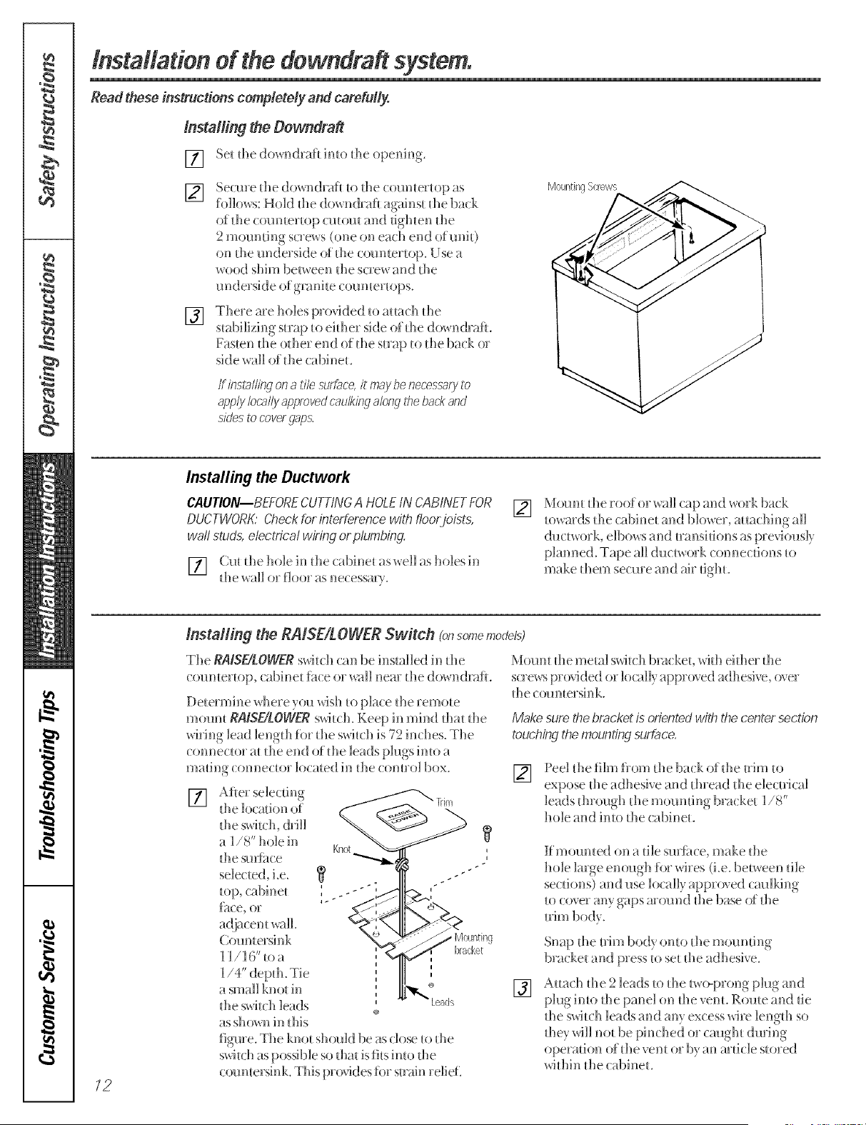
Installing the Dewndraft
[] Se_ d_e dowr_draf_ imo d_e operfir_g.
] Secure die do_,_ndraf_ _o _he (:()_]]_]_e__op as Mounting%revvs
follow, s: Hold d_e do_ ndrafi agains_ d_e ba(k
of the ( oumertop cutout and tighten the
2 ]{]]()l]n[ii]g scKews (one on erich ef]d ()f!]ni[)
on d_e underside of d_e ('oun_er_op. Use 7_
wood shim between _he soew kind _he
underside of gnmi_e coun_eHops.
[]
Thele me holes p_()_ded _o aHa(::h die
stabilizing-map u) eidler side of tile do_ ndrafi.
Fasten die odle_ end of tile sin@ to tile ba(k or
side wall of die cabinet.
If insta/fing on a tile sur£ace,it may be necess-afyto
app/'/ locally approvedcaulking along the back arid
sides to coverg@s,
Installing the Ductwork
CAUTION--BEFORE CUTTkYGA HOLE IN CABINET FOR
DUCTWORK' @eck for interference with fioo,,joists,
wall studs, electrical wiring or plumbing.
[] Cut die hole in die cabinet as_ell as holes in
tile wall o_ f]oo_ as ne(:essm}.
[]
Mount die roof or _all cap and work back
to_ards tile (abinet and blo_er, mmching all
duc[v_oFk, e]bov, s and t_a_lsJtions as pfevio_as]}
}Janned. Tape aH du(:t_, ork (:onne(:dons to
make them se(:ure and air dgb.
/2
Installing the RAISEtL OWER Switch Ig_somemodels)
The RAiSE/LOWER swit dl can be installed in tile
(:ounter_op, (abinet fh(:e or wail near tile do_ n(kafl.
Detem_ine where you t_4sh to place tile remote
mount RAISE/LOWER switch, Keep in mind t]lat the
wiring lead ]engdl for die switch is 72 inches. The
connector at die end of die leads plugs into a
madng ( onnector loomed h-_the ( omro] box.
[]
Aft e_ se]ecdng
the ]ocadon of
the _witc]< dd]]
_ ]/8" hole in
the smii_ce
sele(ted_ i.e.
Countersink
] ]/]6"toa
a small knot in
tile switch leads
as shown in this
figure. The knot shouk] be as (:lose U) tile
s_,@th as possible so flint is fits imo tile
(:ountersink. This provides fi)r suain relief.
Mount tile mem] switch bracket, _it]l eidler the
s(:re_ s provided or locally approved adhesi,,e, over
the countersink.
Make surethe bracket is orientedwith the center section
touchingthemountingsurbce.
[]
Peel tile film flom tile ba(:k of tile trim to
expose die adhesi,,e and dlread die e]e(:uica]
leads dlrou£h tile moundng b_ a(:ket ]/8'
hole and into tlle cabinet.
Kmounted on a tilesm_hce,make the
hole ]mge enough for wi_es (i.e. between die
se(:dons) and use locally approved cm_]king
to cover any gaps m'ound the base ()f the
[]
Snap tile Uim body onto tile mounting
bracket and press to set die adhesive.
Attach die 2 leads to tile two-prong }Jug and
p]u_int()the pan e]on tile_ent.R()_]te and tie
tile s_4t(;]l leads and any excess wi_e ]en_lh so
die,, wi]] not be phlched or caught dmin_
operadon of tile vent o_"b) an mdc]e sto_ed
_4dlin tile cabinet.
Loading ...
Loading ...
Loading ...