Loading ...
Loading ...
Loading ...
8
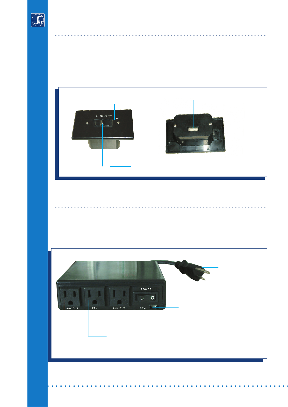
The Proflame Receiver (Fig. 3) connects directly to the gas valve stepper motor, and to the Fan
Control Module with a wiring harness. The receiver is powered by 4 AA type batteries. The
receiver accepts commands via radio frequency from the Transmitter to operate the appliance in
accordance with the particular Proflame system configuration. The Receiver slider switch can be
set to one of these three positions: ON (Manual Override), Remote (Remote control) or OFF.
RECEIVER
Fig. 3: Proflame Receiver body.
12 PIN terminal
Fig. 4: Fan Control Module.
Fan Control Module (FCM) offers the added ability to control the fan speed from off through
six (6) speeds, a remotely actuated 120V outlet, and a constantly powered 120V outlet. The FCM
provides DC power to the receiver allowing the batteries to be used only in the event of line
power loss (Fig.4).
FAN CONTROL MODULE (PROFLAME GTMF & GTMFS only)
MAINS VOLTAGE
SUPPLY CORD
MODULE ON/OFF SWITCH
COMMUNICATION BUS (3 PIN)
FAN OUTLET PLUG
MAINS VOLTAGE PLUG
AUX OUTLET PLUG
3 Positions Slider
PRG Key
Loading ...
Loading ...
Loading ...