Loading ...
Loading ...
Loading ...
10
INSTALLATION
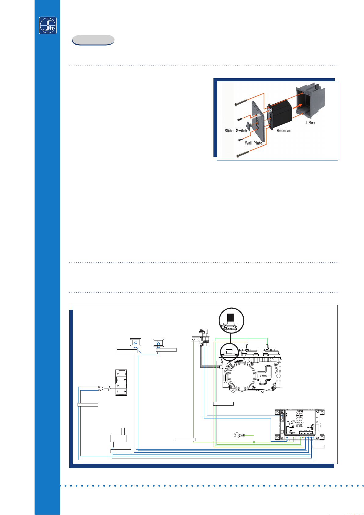
Receiver
The receiver can be placed inside a standard junction type wall box or a low temperature area of
the appliance.
Wall Mounting
1. Connect the wiring harness to the back of the
receiver.
2. Install the receiver in the Junction box using the
existing J box screws. (Fig. 5)
3. Insert the 4 AA type batteries in the battery
compartment with the correct polarity.
4. Place the slider into the cover plate.
5. Put the receiver switch in the “OFF” position.
6. Make sure the receiver and cover plate words
“ON”and “UP” are on the same side.
7. Align the slider with the switch on the receiver and couple the switch into the slider.
8. Align the screw holes.
9. Using the two (2) screws provided secure the cover plate to the receiver.
Hearth Mounting
1. Connect the wiring harness to the back of the receiver.
2. Install the 4 AA type batteries in the battery compartment with the correct polarity.
3. Make sure the receiver and cover plate words “ON” and “UP” are on the same side.
4. Place the slider into the cover plate.
5. Align the slider with the switch on the receiver and couple the switch into the slider.
6. Using the two (2) screws provided secure the cover plate to the receiver.
Fan Control module (PROFLAME GTMF & GTMFS only), and DFC control board
The FCM must be placed in a low temperature area of the appliance.
The Proflame DFC board should be placed in a low temperature area of the appliance.
Fig. 5
Fig. 6A: Proflame Standalone & 880/886 PROFLAME wiring diagram.
Connecting to the 880/886 Gas Valve and DFC control board
The electrical connections must be in accordance to Fig. 6A.
Orange
Green
Red
Black
880/886 Proflame
Battery
Holder
Chassis
connection
120 Vac INPUT
7 Vdc STABILIZED
SUPPLY OUTPUT
ON / OFF
CPI / IPI MODE
ON/OFF
IPI/CPI
BATTERY
DC SUPPLY
VALVE
GROUND
DFC
Loading ...
Loading ...
Loading ...