WWW.VINOTEMP.COM
A PROUD HERITAGE OF EXPERIENCE & QUALITY
INSTALLATION MANUAL
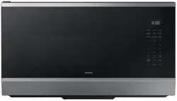
30” OVER THE RANGE
MICROWAVE OVEN
EM044K6BB ( BR- MW OH16- S )
2
WWW.VINOTEMP.COM
!
!
PARTS AND SPECIFICATIONS
Model
EM044K6BB (BR-MW OH16-S)
Rated Voltage/Frequency
120V / 60Hz
Rated Input Power (Microwave):
1550W
Rated Output Power (Microwave):
1000W
Microwave Oven Capacity
1.6 cu. ft.
Turntable Diameter:
13.5 in (34.5 cm)
External Dimensions (W x D x H)
31.3 x 16.4 x 15.0 in
Internal Dimensions (W x D x H)
20.24 x 14.41 x 9.25 in
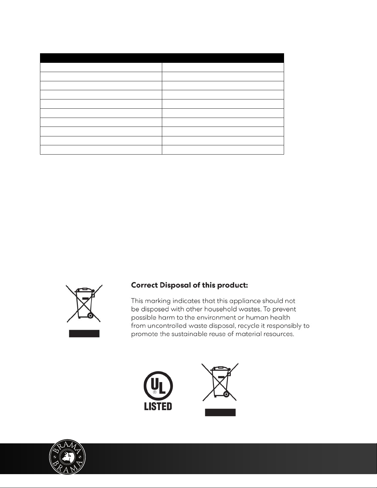
Certifications
UL approved
Power Cord length
3.3 ft. (1 m)
Net Weight
56 lbs. (25.4 kg)

Contents
Introduction . . . . . . . . . . . . . . . . . . . . . . . . . . . . . . . . . . . . . . . . . . . . . . . . . . . . . . . . . . . 4
BEFORE YOU BEGIN . . . . . . . . . . . . . . . . . . . . . . . . . . . . . . . . . . . . . . . . . . . . . . . . . . . . 4
IMPORTANT SAFETY INSTRUCTIONS . . . . . . . . . . . . . . . . . . . . . . . . . . . . . . . . . . . . 4
ELECTRICAL REQUIREMENTS . . . . . . . . . . . . . . . . . . . . . . . . . . . . . . . . . . . . . . . . . . . . . . . . . . . . . . . . . . .4
Package contents . . . . . . . . . . . . . . . . . . . . . . . . . . . . . . . . . . . . . . . . . . . . . . . . . . . . . . . 5
Parts . . . . . . . . . . . . . . . . . . . . . . . . . . . . . . . . . . . . . . . . . . . . . . . . . . . . . . . . . . . . . . . . . . . . . . . . . . . . . . . . . 5
Hardware . . . . . . . . . . . . . . . . . . . . . . . . . . . . . . . . . . . . . . . . . . . . . . . . . . . . . . . . . . . . . . . . . . . . . . . . . . . . . 5
Before you install . . . . . . . . . . . . . . . . . . . . . . . . . . . . . . . . . . . . . . . . . . . . . . . . . . . . . . .6
Tools and materials needed . . . . . . . . . . . . . . . . . . . . . . . . . . . . . . . . . . . . . . . . . . . . . . . . . . . . . . . . . . . .6
Mounting requirements . . . . . . . . . . . . . . . . . . . . . . . . . . . . . . . . . . . . . . . . . . . . . . . . . . . . . . . . . . . . . . . 7
Exhaust requirements . . . . . . . . . . . . . . . . . . . . . . . . . . . . . . . . . . . . . . . . . . . . . . . . . . . . . . . . . . . . . . . . . 8
Removing your microwave . . . . . . . . . . . . . . . . . . . . . . . . . . . . . . . . . . . . . . . . . . . . . .10
Installing your microwave . . . . . . . . . . . . . . . . . . . . . . . . . . . . . . . . . . . . . . . . . . . . . . .11
Step 1: Find the wall studs . . . . . . . . . . . . . . . . . . . . . . . . . . . . . . . . . . . . . . . . . . . . . . . . . . . . . . . . . . . . .11
Step 2: Align the rear wall template . . . . . . . . . . . . . . . . . . . . . . . . . . . . . . . . . . . . . . . . . . . . . . . . . . . .12
Step 3: Select a ventilation type . . . . . . . . . . . . . . . . . . . . . . . . . . . . . . . . . . . . . . . . . . . . . . . . . . . . . . . .14
Step 4: Option A - Attach the mounting plate to the wall . . . . . . . . . . . . . . . . . . . . . . . . . . . . . . . .15
Step 5: Option A - Preparing the top cabinet . . . . . . . . . . . . . . . . . . . . . . . . . . . . . . . . . . . . . . . . . . . .17
Step 6: Option A - Adapt the microwave blower for outside top exhaust . . . . . . . . . . . . . . . . . 19
Step 7: Option A - Mount the microwave . . . . . . . . . . . . . . . . . . . . . . . . . . . . . . . . . . . . . . . . . . . . . . . 21
Step 8: Option A - Connecting duct work . . . . . . . . . . . . . . . . . . . . . . . . . . . . . . . . . . . . . . . . . . . . . . .23
Step 4: Option B - Cutting a vent opening . . . . . . . . . . . . . . . . . . . . . . . . . . . . . . . . . . . . . . . . . . . . . . 24
Step 5: Option B - Attach the mounting plate to the wall . . . . . . . . . . . . . . . . . . . . . . . . . . . . . . . . 25
Step 6: Option B - Preparing the top cabinet . . . . . . . . . . . . . . . . . . . . . . . . . . . . . . . . . . . . . . . . . . . .27
Step 7: Option B - Adapt the microwave blower for outside back exhaust . . . . . . . . . . . . . . . .29
Step 8: Option B - Mount the microwave . . . . . . . . . . . . . . . . . . . . . . . . . . . . . . . . . . . . . . . . . . . . . . . 32
Step 4: Option C - Attach the mounting plate to the wall . . . . . . . . . . . . . . . . . . . . . . . . . . . . . . . . 34
Step 5: Option C - Preparing the top cabinet . . . . . . . . . . . . . . . . . . . . . . . . . . . . . . . . . . . . . . . . . . . . 36
Step 6: Option C - Mount the microwave . . . . . . . . . . . . . . . . . . . . . . . . . . . . . . . . . . . . . . . . . . . . . . . 38
Before using your microwave . . . . . . . . . . . . . . . . . . . . . . . . . . . . . . . . . . . . . . . . . . . 40
Obtaining replacement parts . . . . . . . . . . . . . . . . . . . . . . . . . . . . . . . . . . . . . . . . . . . . 40
Specifications . . . . . . . . . . . . . . . . . . . . . . . . . . . . . . . . . . . . . . . . . . . . . . . . . . . . . . . . . . 40
Template dimensions . . . . . . . . . . . . . . . . . . . . . . . . . . . . . . . . . . . . . . . . . . . . . . . . . . . 41
Rear wall template dimensions . . . . . . . . . . . . . . . . . . . . . . . . . . . . . . . . . . . . . . . . . . . . . . . . . . . . . . . . 41
Top cabinet template dimensions . . . . . . . . . . . . . . . . . . . . . . . . . . . . . . . . . . . . . . . . . . . . . . . . . . . . . . 42
Terms & Conditions . . . . . . . . . . . . . . . . . . . . . . . . . . . . . . . . . . . . . . . . . . . . . . . . . . . . 43
WARRANTY . . . . . . . . . . . . . . . . . . . . . . . . . . . . . . . . . . . . . . . . . . . . . . . . . . . . . . . . . . . . 50
3
732 South Racetrack Road, Henderson, Nevada 89015
info@vinotemp.com
Introduction
This installation guide will show you how to install your new over-the-range microwave.
BEFORE YOU BEGIN
Read these instructions completely and carefully.
• IMPORTANT – Save these instructions for local inspector’s use.
• IMPORTANT – Observe all governing codes and ordinances.
• Note to Installer – Be sure to leave these instructions with the consumer.
• Note to Consumer – Keep these instructions for future reference.
• Skill level – Installation of this appliance requires basic mechanical and electrical skills.
• Proper installation is the responsibility of the installer.
• Product failure due to improper installation is not covered under the Warranty.
IMPORTANT SAFETY INSTRUCTIONS
IMPORTANT–PLEASE READ CAREFULLY. FOR PERSONAL SAFETY, THIS APPLIANCE MUST BE PROPERLY GROUNDED
TO AVOID SEVERE OR FATAL SHOCK.
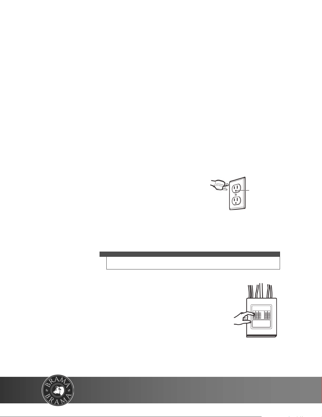
This product requires a three-prong, properly grounded outlet for safe
operation. If not properly grounded, or if the outlet box does not meet
electrical requirements noted (under ELECTRICAL REQUIREMENTS), a qualified
electrician should be employed to correct any deficiencies.
The power cord of this appliance is equipped with a three-prong (grounding)
plug which mates with a standard three-prong (grounding) wall receptacle to
minimize the possibility of electric shock hazard from this appliance.
You should have the wall receptacle and circuit checked by a qualified electrician to make sure that the receptacle is
properly grounded.
Where a standard two-prong wall receptacle is encountered, it is very important to have it replaced with a properly
grounded three-prong wall receptacle installed by a qualified electrician.
DO NOT, UNDER ANY CIRCUMSTANCES, CUT, DEFORM, OR REMOVE ANY OF THE PRONGS FROM THE POWER CORD.
DO NOT USE WITH AN EXTENSION CORD.
Caution
For personal safety, remove the house fuse or open the circuit breaker before beginning
installation to avoid severe or fatal shock injury.
For personal safety, the mounting surface must be capable of supporting the cabinet load,
in addition to the added weight of this 56-lb. (25.4 kg) product, plus additional oven loads
of up to 50 pounds (22 kilograms) for a total weight of 106 lbs. (46.4 kg).
For personal safety, this product cannot be installed in cabinet arrangements such as an
island or a peninsula. It must be mounted to BOTH a top cabinet AND a wall.
ELECTRICAL REQUIREMENTS
The product rating of your microwave is 120 volts AC, 60 Hertz, 15 amps, and 1.6 kilowatts. This product must be
connected to a supply circuit of the proper voltage and frequency. Wire size must conform to the requirements of
the National Electrical Code or the prevailing local code for this kilowatt rating. The power supply cord and plug
should be brought to a separate 20 ampere branch circuit single grounded outlet. The outlet box should be located
in the cabinet above the microwave oven. The outlet box and supply circuit should be installed by a qualified
electrician and conform to the National Electrical Code or the prevailing local code.
Note
For easier installation and personal safety, it is recommended that two people
install this product.
Ensure proper
ground before
use
Congratulations on your purchase of a high-quality product. Your represents the state of the art in microwave
design and is designed for reliable and trouble-free performance.
4
WWW.VINOTEMP.COM
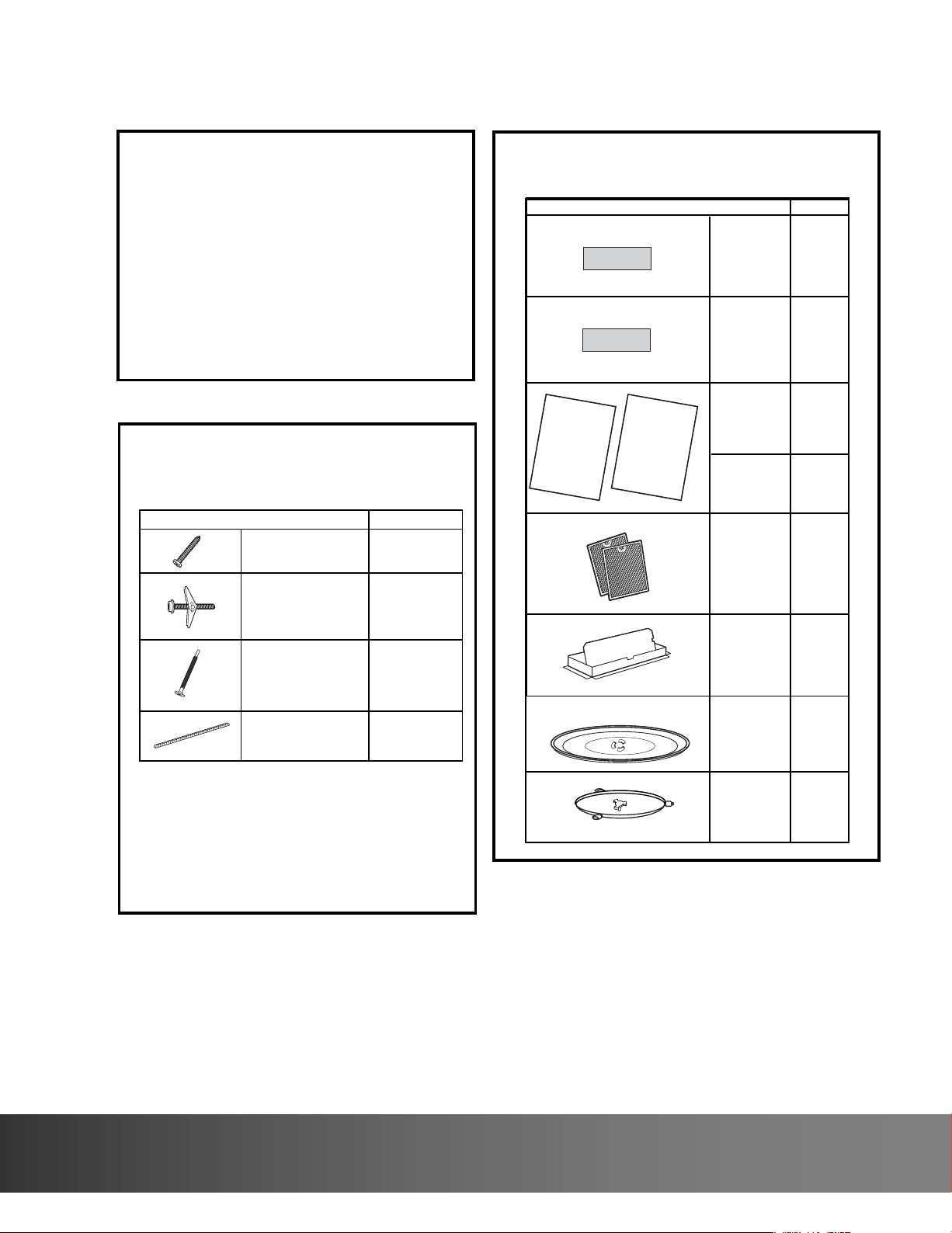
PART QUANTITY
Wood Screws 2
(
1
⁄
4
“ x 2“)
Toggle Bolts (and
wing nuts) (
3
⁄
16
“ x 3“)
Self-Aligning Machine 3
Screws (
1
⁄
4
“-28 x 3
1
⁄
4
“)
Nylon Grommet
(for metal cabinets)
1
•
If the unit is damaged in shipment, return the
unit to the store in which it was bought for repair
or replacement.
•
If the unit is damaged by the customer, repair or
replacement is the responsibility of the customer.
•
If the unit is damaged by the installer (if other
than the customer), repair or replacement must
be made by arrangement between customer
and installer.
DAMAGE—SHIPMENT/
INSTALLATION
PARTS INCLUDED
You will find the installation hardware contained in
a packet with the unit. Check to make sure you have
all these parts.
NOTE: Some extra parts are included.
HARDWARE PACKET
PART
QUANTITY
Template
1
Template
Installation
1
Instructions
Separately
2
Packed
Filters
PARTS INCLUDED
(CONT.)
INSTALLATION
IN
STRUCTIONS
ADDITIONAL PARTS
1
adaptor
Exhaust
Glass
1
Tray
1
Ring
T ru ntable
CabinetTop
Rear
Wall
2
1
Use & Care
1
USE & CARE
MANUAL
Manual
Grease
5
732 South Racetrack Road, Henderson, Nevada 89015
info@vinotemp.com
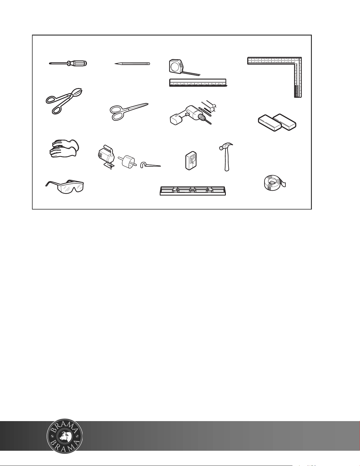
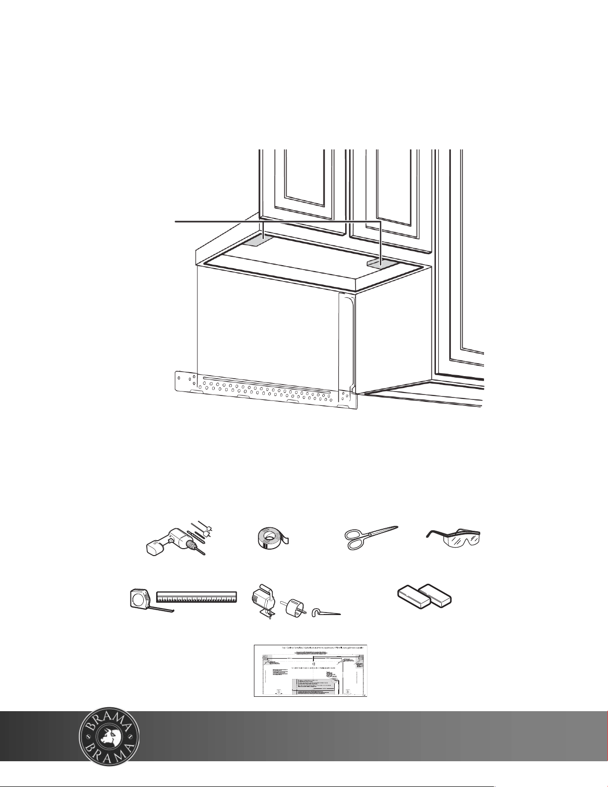
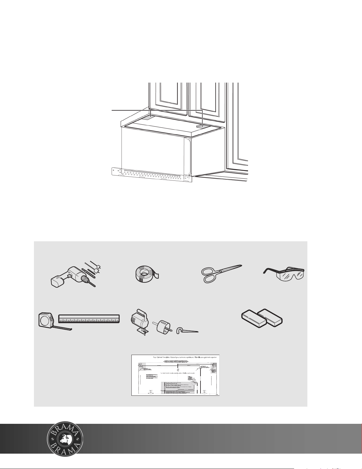
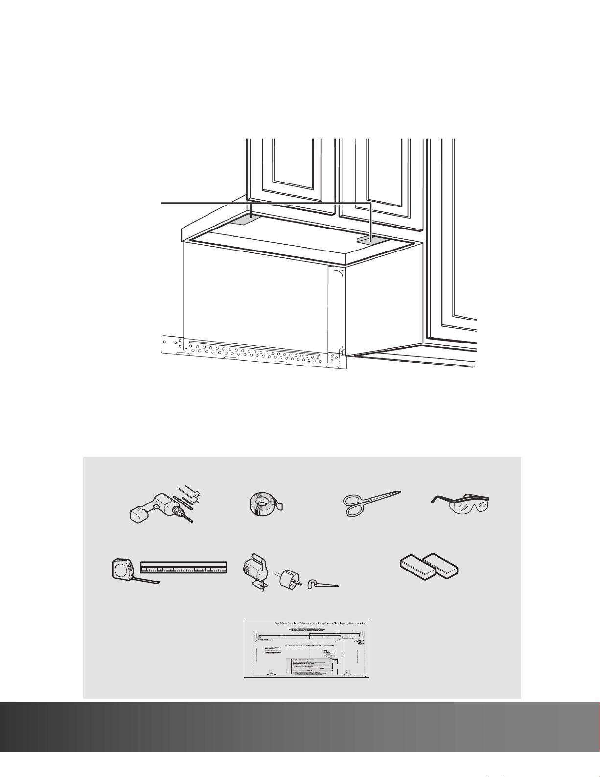
TOOLS YOU WILL NEED
# 1 Phillips screwdriver
Pencil
Ruler or tape measure and
straight edge
Carpenter square
(optional)
Tin snips (for cutting
damper, if required)
Electric drill with
3
⁄
16
“,
1
⁄
2
“ and
5
⁄
8
“
drill bits
Hammer (optional)
Stud finder or
Filler blocks or scrap
wood pieces, if needed
for top cabinet spacing
(used on recessed bottom
cabinet installations only)
Gloves
Saw (saber, hole or keyhole)
Level
Duct and masking tape
Scissors
(to cut template, if necessary)
Safety goggles
6
WWW.VINOTEMP.COM
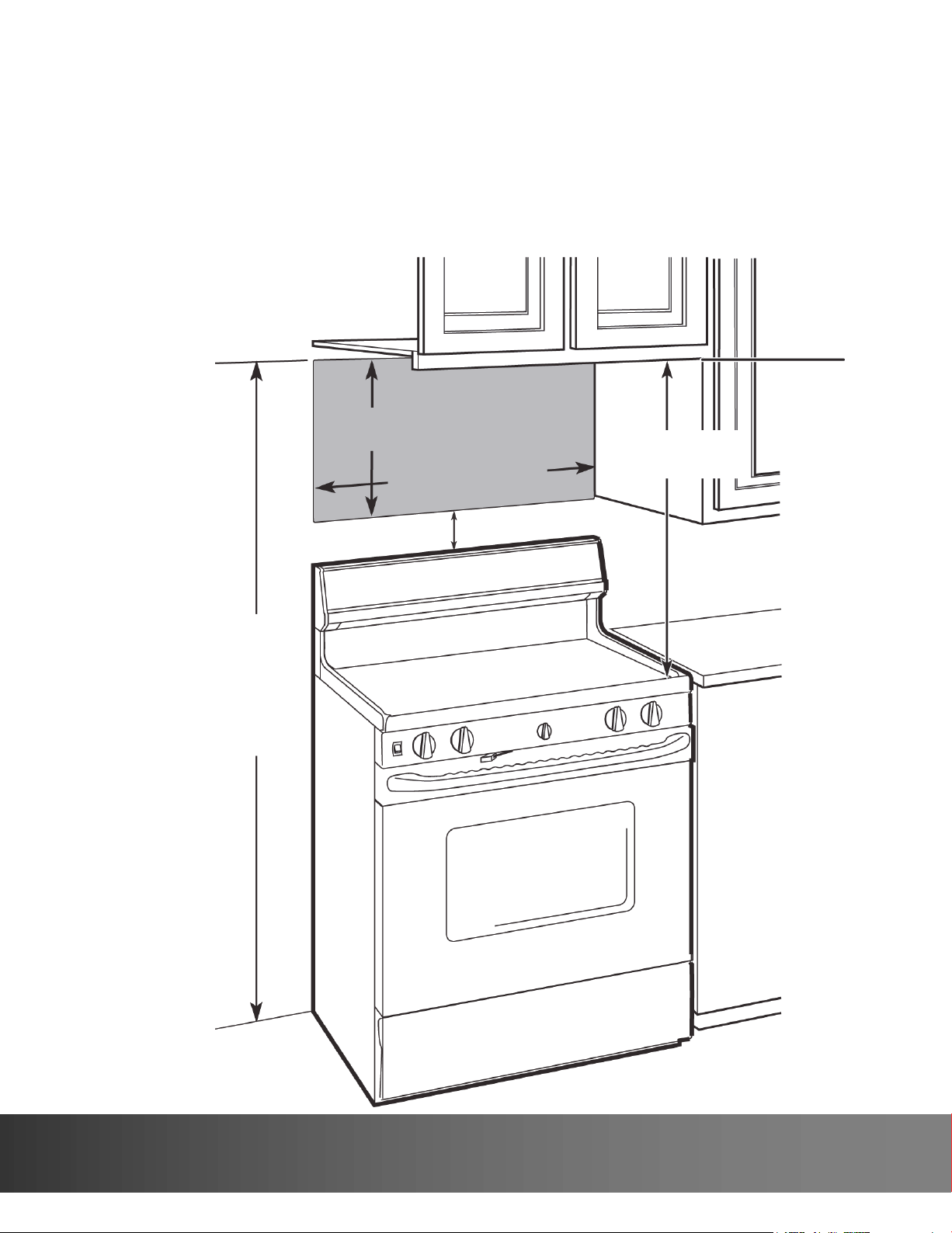
66 in. (167.6 cm) or more
from the floor to the top of
the microwave
16-1/2 in.
(41.9 cm)
3
0
i
n
.
(
7
6
.
2
cm)
30 in.
(76.2 cm)
2 in. (5.1 cm)
Mounting requirements
• The space between the cabinets must be 30 in. (76.2 cm) wide. If the space between
the cabinets is more than 30 in. (76.2 cm), you’ll need filler material to fill the gap
between the microwave and cabinets.
• This microwave is for installation over ranges up to 36 in. (91.4 cm) wide.
• If installing the microwave beneath smooth, flat cabinets, make sure that you leave
enough space for the power cord clearance.
• If you are going to vent your exhaust to the outside, see “Exhaust requirements” on
page 8 for exhaust duct preparation.
7
732 South Racetrack Road, Henderson, Nevada 89015
info@vinotemp.com
Exhaust requiremen
ts
Use this section if you plan to vent your microwave outside (top or back exhaust). If you plan
to recirculate the air back into the room, skip to “Removing your microwave” on page 9.
When installing exhaust vents:
• Use the most direct route with as few elbows/transitions as possible. This helps prevent
blockages and ensures
that the exhaust is being vented correctly.
• Your microwave is designed to mate with a standard 3-1/4” × 10” rectangular duct. If a
round duct is required, a
rectangular-to-round transition adapter must be used. Do not use a duct with a diameter
less than 6”.
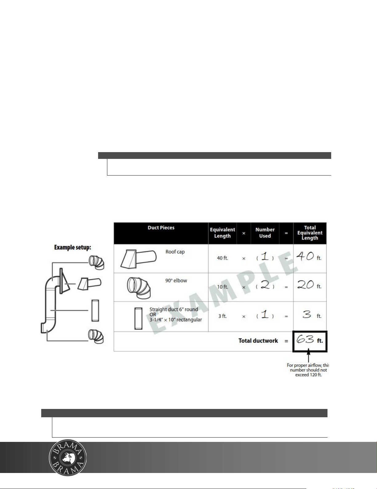
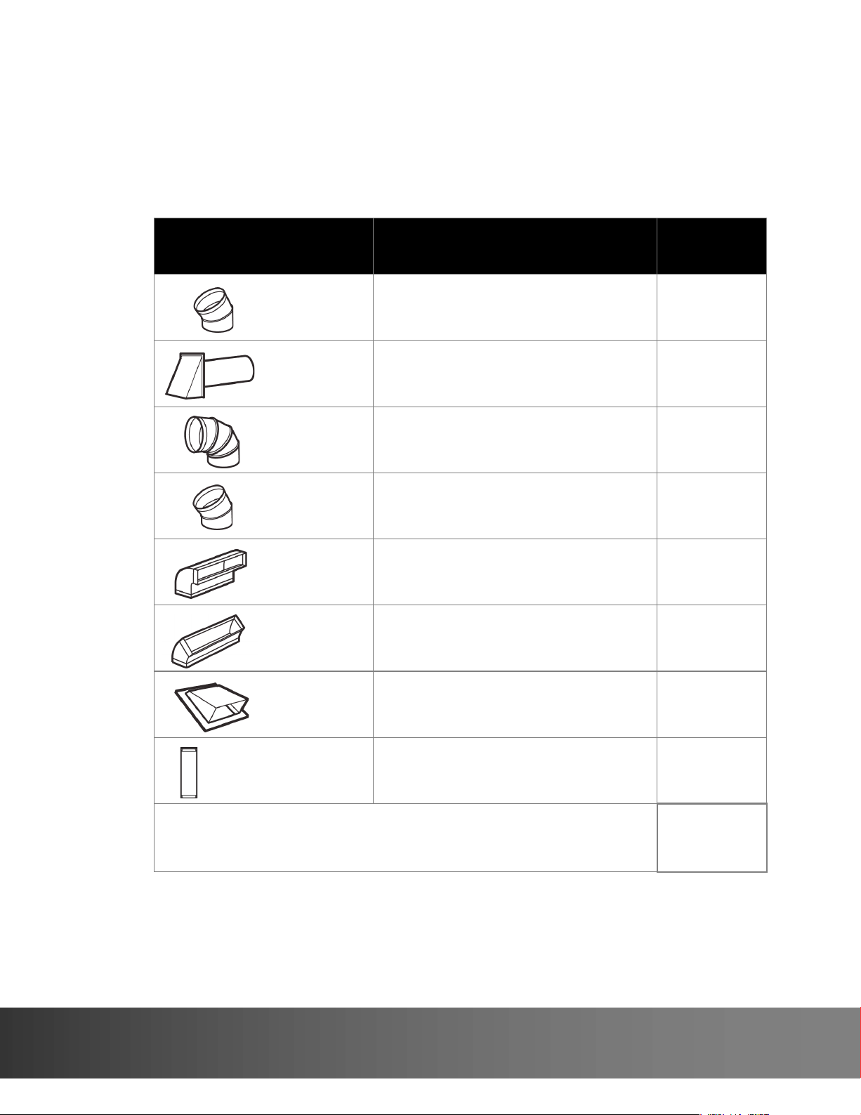
• Elbows, transitions, and wall/roof caps add resistance to airflow. Each of these pieces are equivalent to a section
of straight duct that is longer than their actual physical size. When calculating yo
ur duct length, add the
equivalent lengths of all the pieces together. For proper airflow, the equivalent airflow should not exceed 120 ft.
For example:
Note
If a rectangular-to-round transition adapter is used, you must cut the bottom
corners of the damper wih tin snips to let the damper have free movement.
Note
Equivalent lengths of duct pieces are based on actual tests and reflect
requirements for good venting performance with any vent hood.
Use the “Equivalent duct length table” on page 9 to calculate
the equivalent duct-work length for your setup.
8
WWW.VINOTEMP.COM
To calculate your equivalent duct length:
1 Write the number of sections used for each of the duct pieces.
2 Multiply the number used by the equivalent length for each duct piece.
3 Add the total equivalent lengths together. This number must be less than 120 ft.
Duct Pieces
Equivalent
Length
× Number Used =
Tot al
Equivalent
Length
5 ft. × ( ) = ft.
40 ft. × ( ) = ft.
10 ft. × ( ) = ft.
5 ft. × ( ) = ft.
25 ft. × ( ) = ft.
5 ft. × ( ) = ft.
24 ft. × ( ) = ft.
1 ft. × ( ) = ft.
Total ductwork =
ft.
(For proper airflow, this
number should not
exceed 120 ft.)
Rectangular-to-
round transition
adapter
Wall cap
90° elbow
45° elbow
90° elbow
45° elbow
Roof cap
Straight duct 6” round
OR
3-1/4” × 10” rectangular
Equivalent duct length table
9
732 South Racetrack Road, Henderson, Nevada 89015
info@vinotemp.com
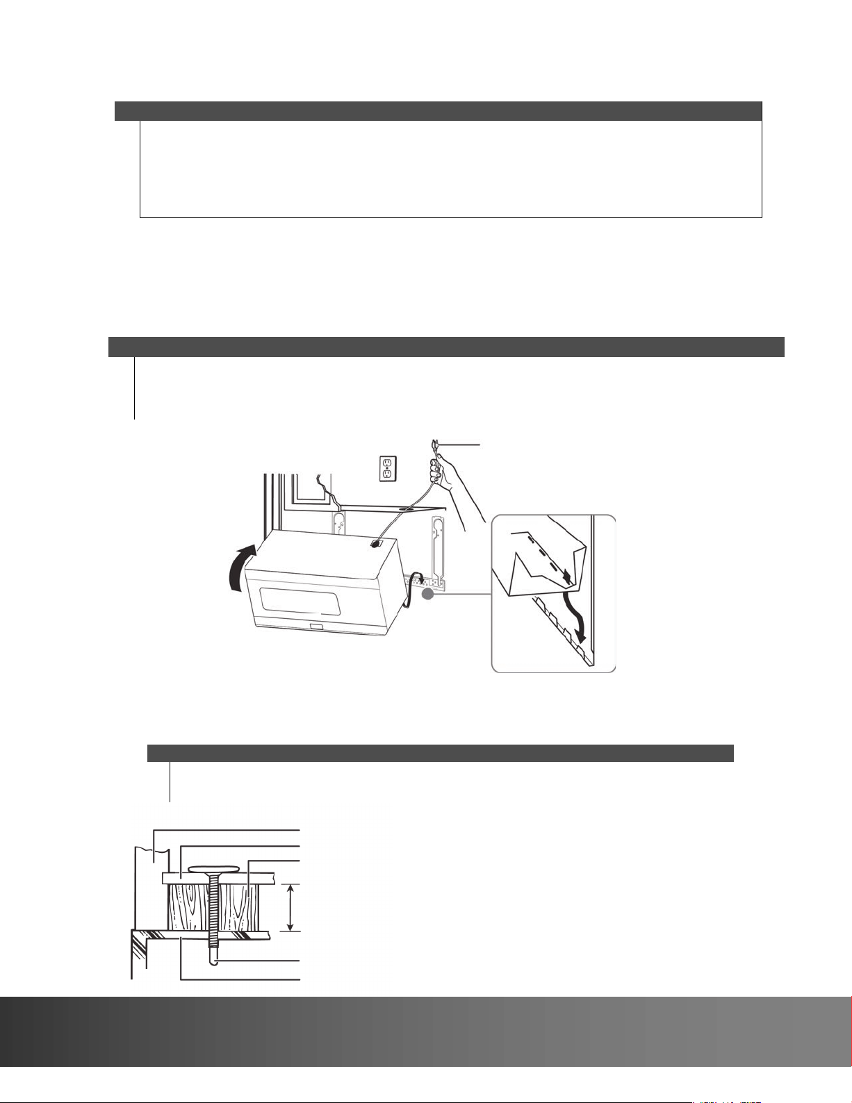
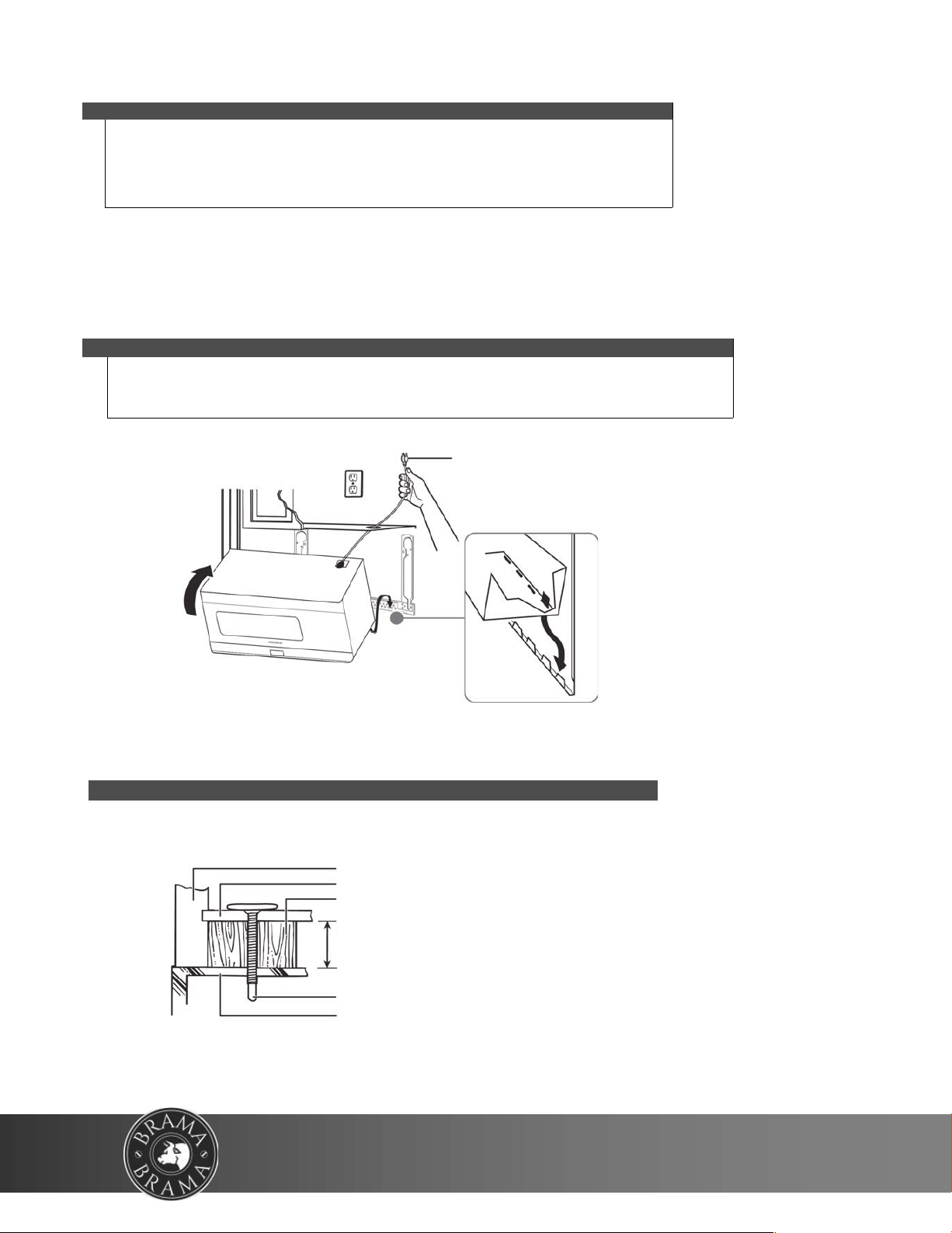
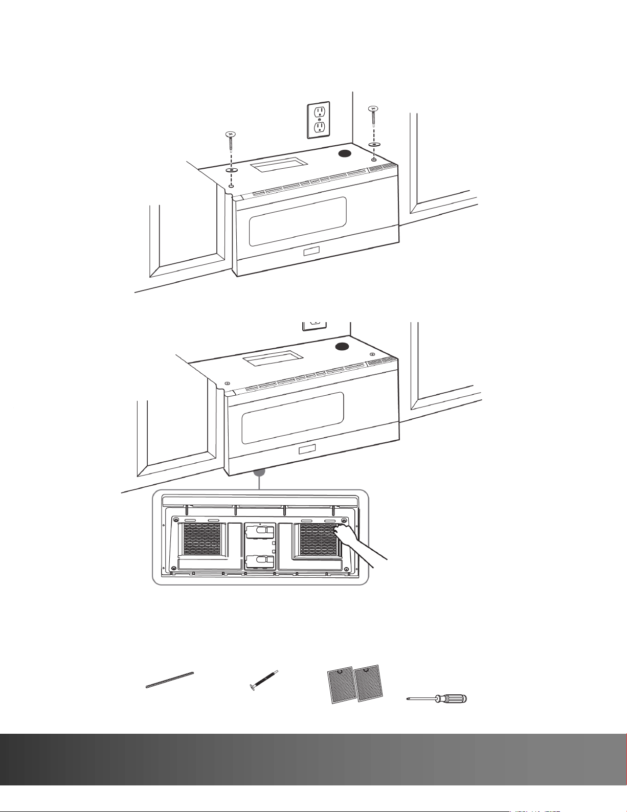
Removing y
our microwave
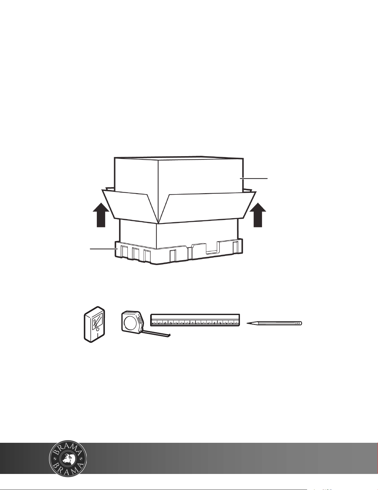
1 Remove the documentation, filters, glass tray, and hardware bag from
the box. Do not remove the Styrofoam protecting the front of your mi-
crowave.
2 Fold back all four box flaps, then carefully roll the microwave and box
over onto the top side. The microwave should be resting in the Styro-
foam.
3 Pull the box up and off the microwave.
4 Remove and throw away the plastic bags.
Styrofoam
Box
You’ll need:
Edge-to-edge stud finder
Ruler or tape measure Pencil
10
WWW.VINOTEMP.COM
Installing your microwave
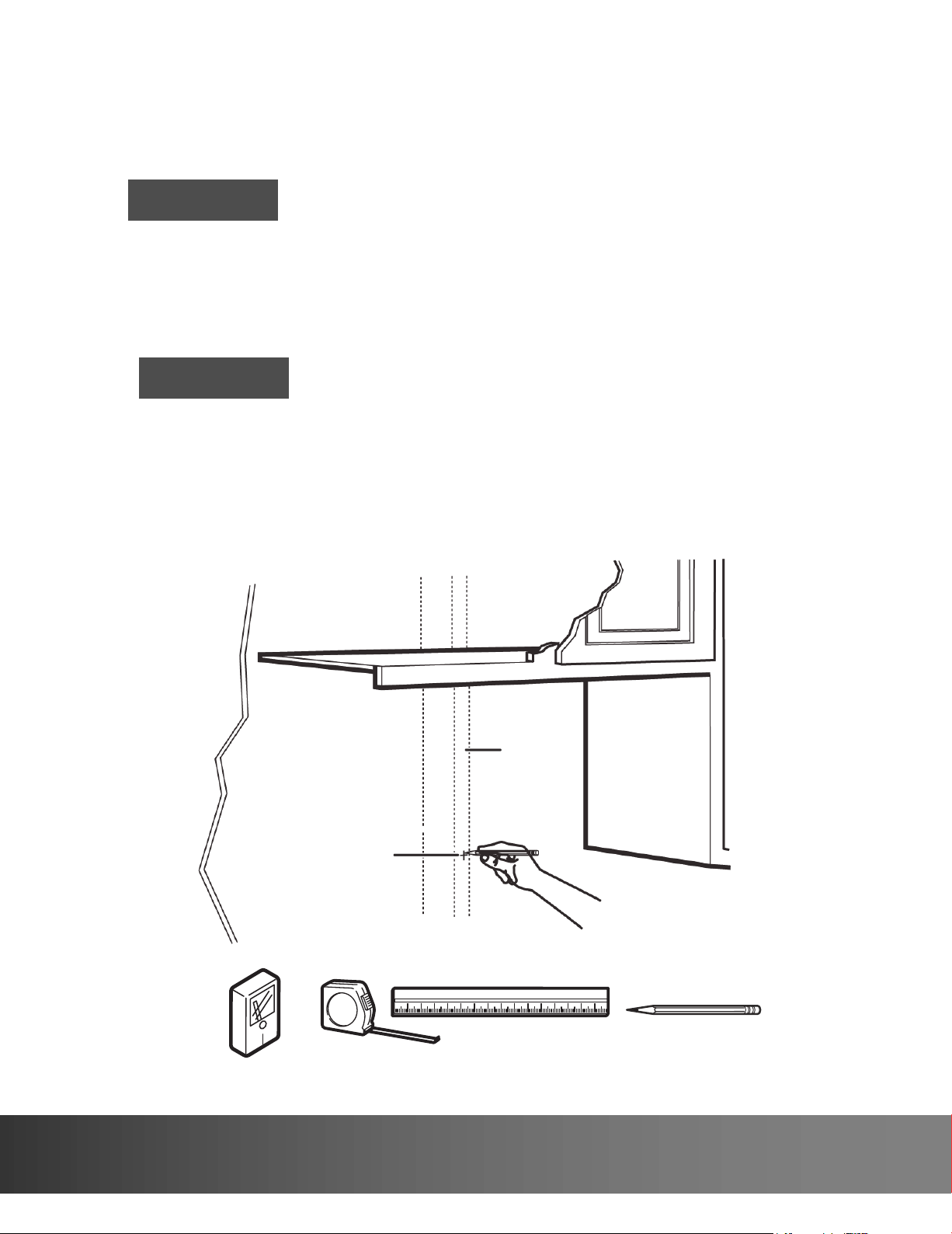
Step 1: Find the wall studs
1 Using an edge-to-edge stud finder, locate the edges of the
wall stud(s) within the opening.
2 Mark the center of each stud, and then draw a vertical line
down the center of each stud.
Warning
Your microwave must be connected to at least one wall stud.
The center of any adjacent wall studs should be 16" or 24" from this mark.
Wall
stud
Center of the
wall stud
Warning
You’ll need:
Edge-to-edge stud finder
Ruler or tape measure Pencil
11
732 South Racetrack Road, Henderson, Nevada 89015
info@vinotemp.com
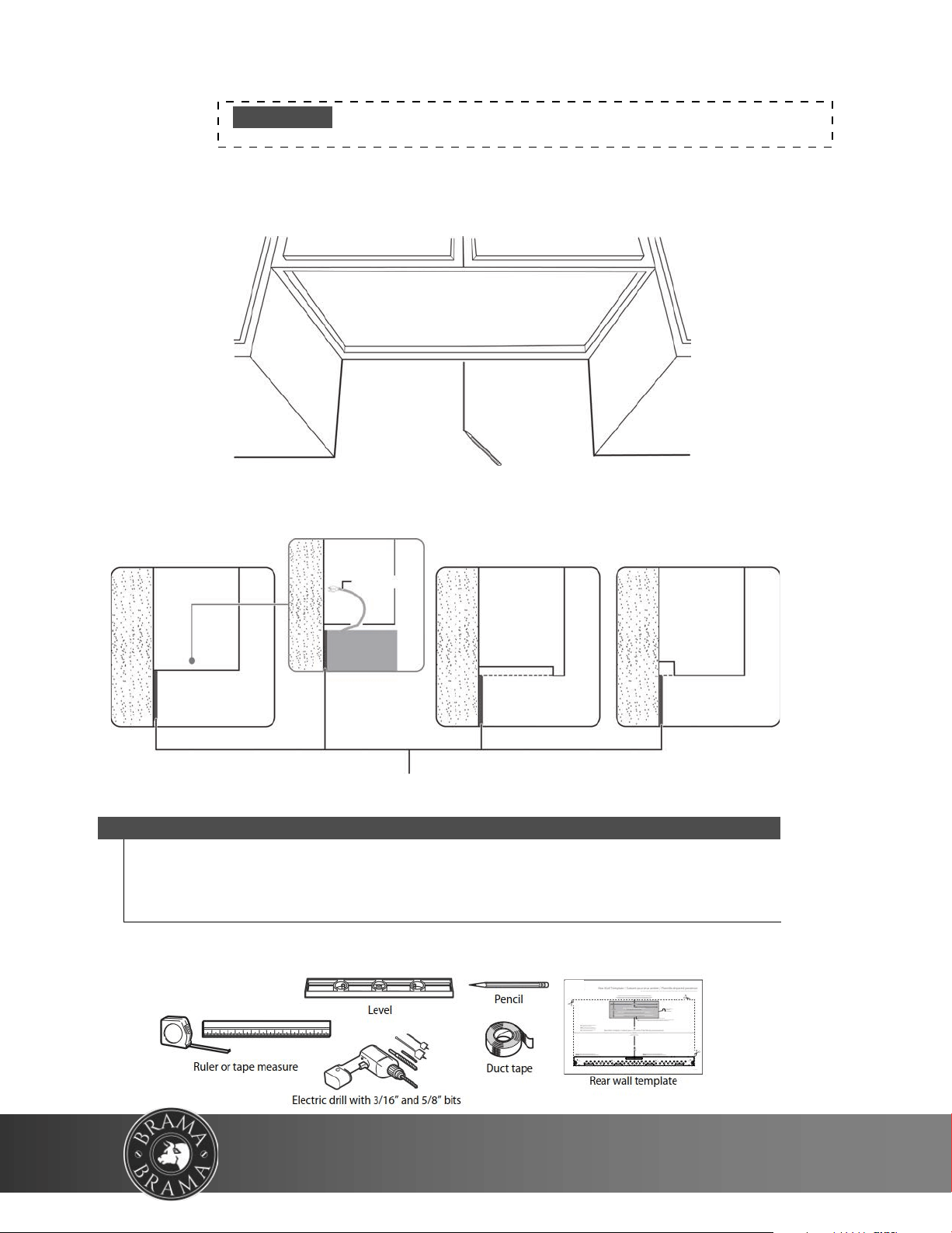
4 Trim the rear wall template along the dotted line.
Step 2: Align the rear wall template
If the rear wall template is damaged or unusable, see “Rear wall template
dimensions” on page 40 for dimensions.
Notes
• If installing the microwave beneath smooth, flat cabinets, make sure that you leave
enough space for the power cord cl
earance.
• If cabinets have decorative trim that interferes with the microwave installation,
remove the trim to install the microwave properly and to make sure that it is level.
Rear wall template
Power cord
Cabinet
Cabinet
Cabinet
Cabinet
W
A
L
L
W
A
L
L
W
A
L
L
Flat bottom:
Front overhang:
Recessed back:
NOTE:
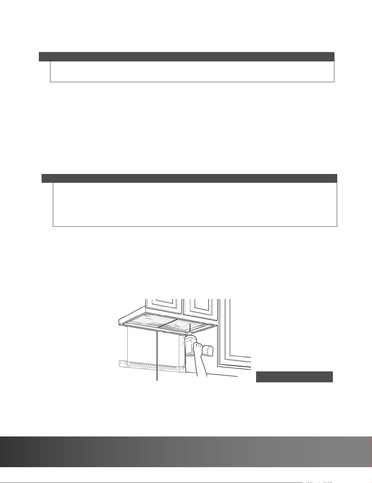
1 Use a level to make sure that the bottom of the cabinet is level.
2 Draw a vertical line down the center of the wall in the mounting space.
This is where the center of your template will be.
3 Draw a horizontal line at the height of the front of your cabinet. This is where the top of your template will
be. If the bottom of your cabinet is flat, make sure that you leave space for the power cord.
12
WWW.VINOTEMP.COM
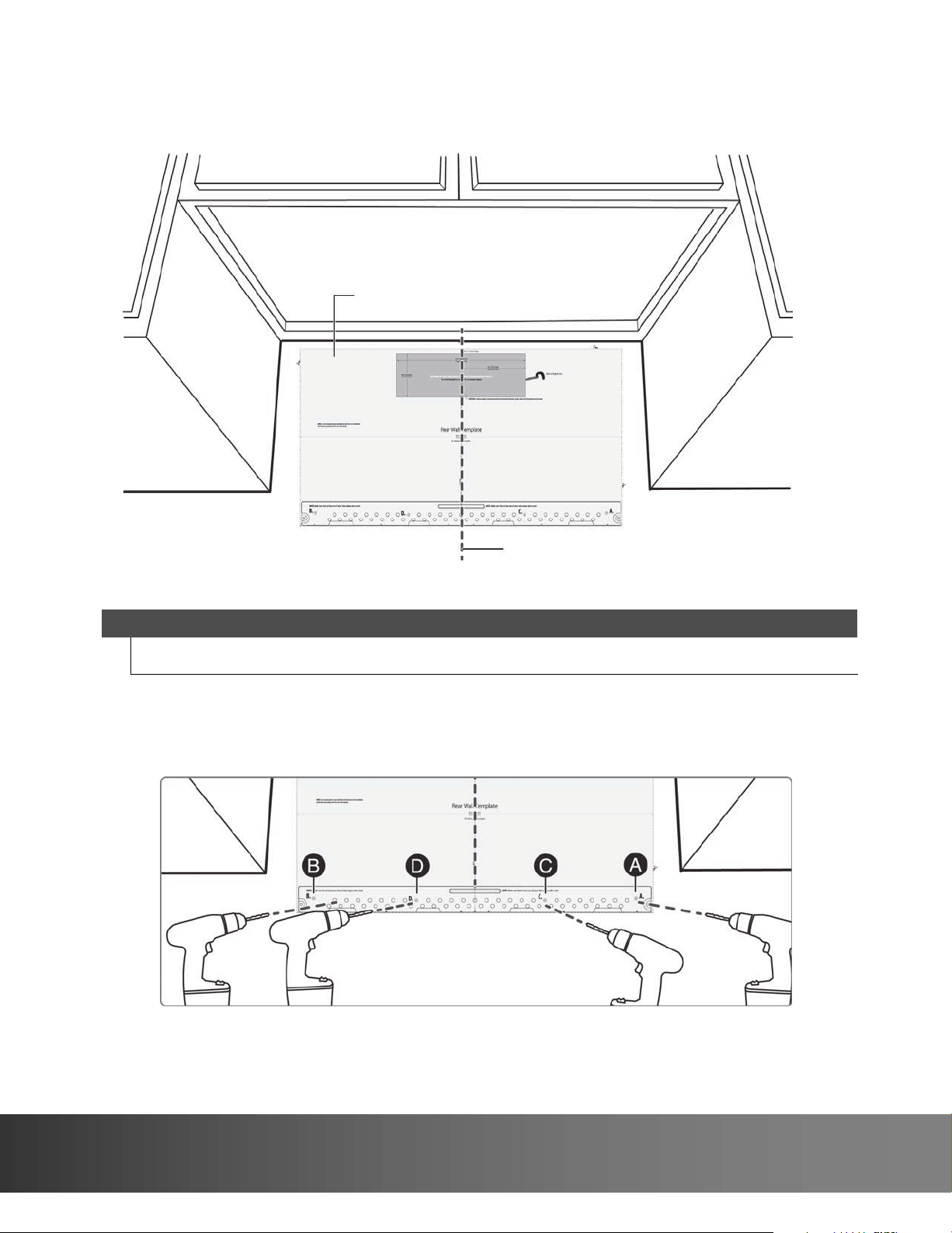
5 Tape the template in place so that it is centered on the vertical line and
the top edge is aligned with the horizontal line.
Vertical line in the center
Top of the template aligned
with the horizontal line
6 Find a hole that aligns with a stud (this is C or D).
CAUTION
You must mount to at least one stud.
7 Drill holes through the template at points A, B, and C or D. If the hole lines up
with a stud, drill a 3/16” hole. Otherwise, drill a 5/8" hole for the toggle bolts. You
must use at least three holes for mounting.
Note: Depending on your stud locations, your installation may look
different. You should mount to at least one stud.
13
732 South Racetrack Road, Henderson, Nevada 89015
info@vinotemp.com
Option A - Outside top exhaust (vertical duct):
Option B - Outside back exhaust (horizontal duct):
Option C - Recirculating (non-vented/ductless):
Step 3: Select a ventilation type
This microwave is designed for three types of ventilation. Select the type of ventilation you want to use, then go to
the corresponding page.
Note
This microwave is shipped assembled for recirculating ventilation.
Adapter
*Requires a charcoa
l
filter (included)
14
WWW.VINOTEMP.COM
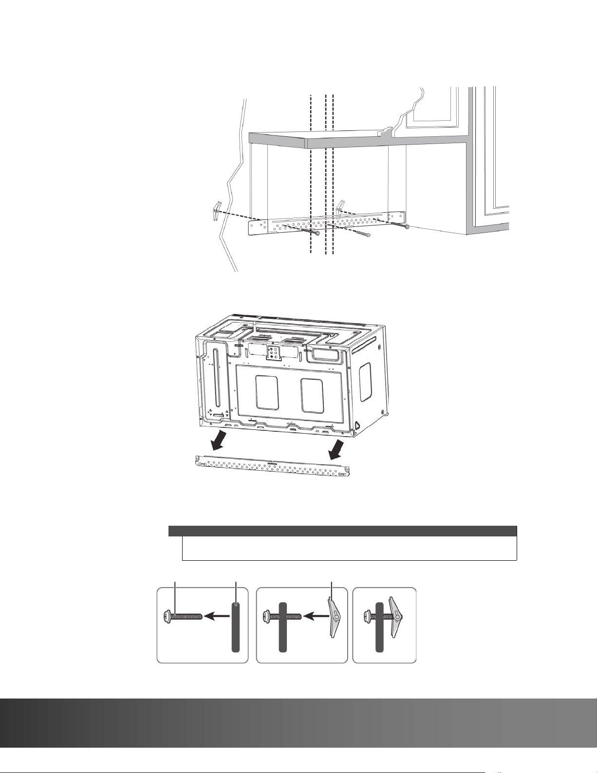
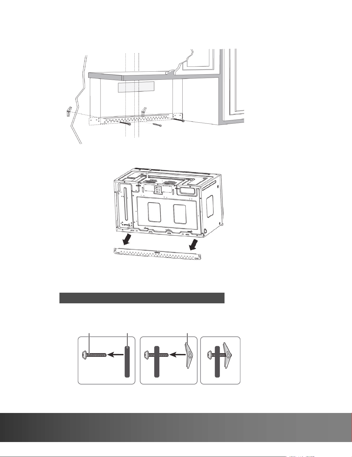
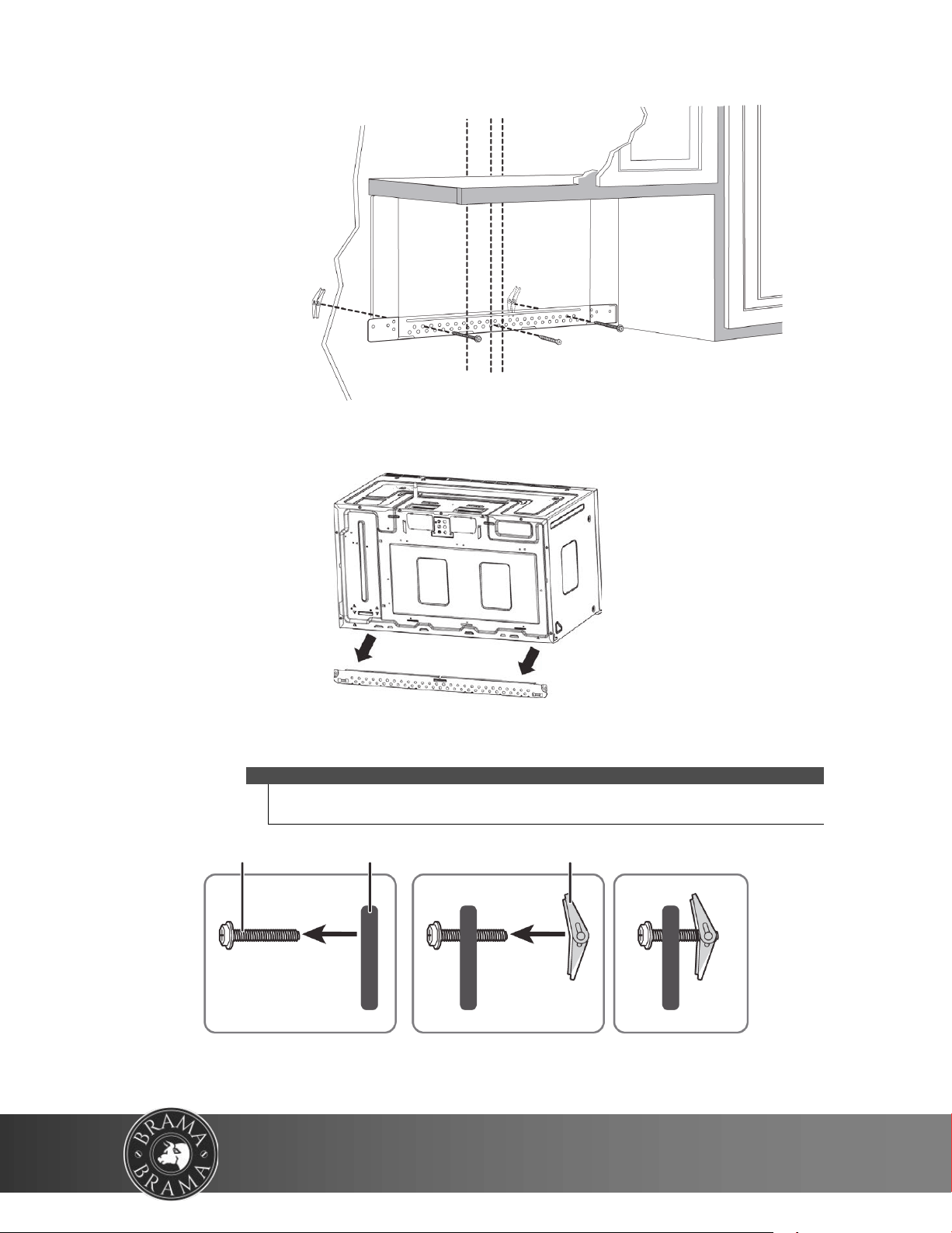
Step 4: Option A - Attach the mounting plate to the wall
1 Remove the rear wall template.
2 Remove the mounting plate from the back of your microwave using a Phillips screwdriver.
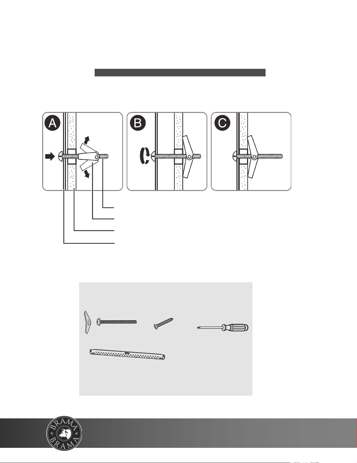
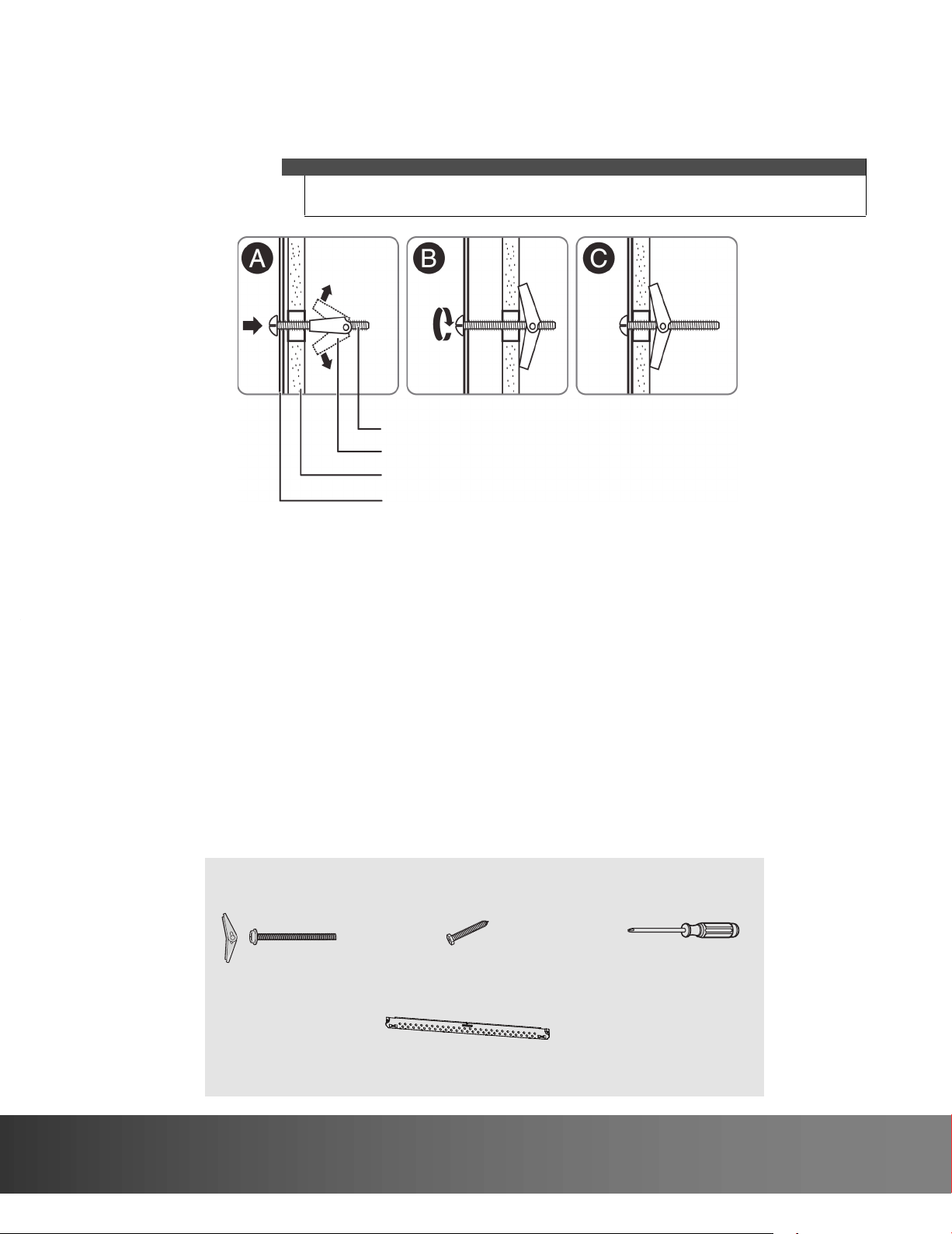
3 Insert the toggle bolt(s) through the front of the mounting plate into the hole(s) that are not going into a stud,
and then attach the toggle wings ¾" onto each bolt. Hold your mounting plate up to holes in your wall to
identify the correct position.
4 Place the mounting plate against the wall and insert the toggle wings into the holes you drilled in the drywall.
Pull the mounting plate away from the wall to help tighten the toggle wings.
Note
The top of the mounting plate is indicated with an arrow. The mounting plate’s
hooks are on the front.
Note: Depending on
your stud locations, your
installation may look
different. You should
insert toggle bolts into
drywall and wood screws
into studs.
Bolt
Wing
Mounting plate
15
732 South Racetrack Road, Henderson, Nevada 89015
info@vinotemp.com
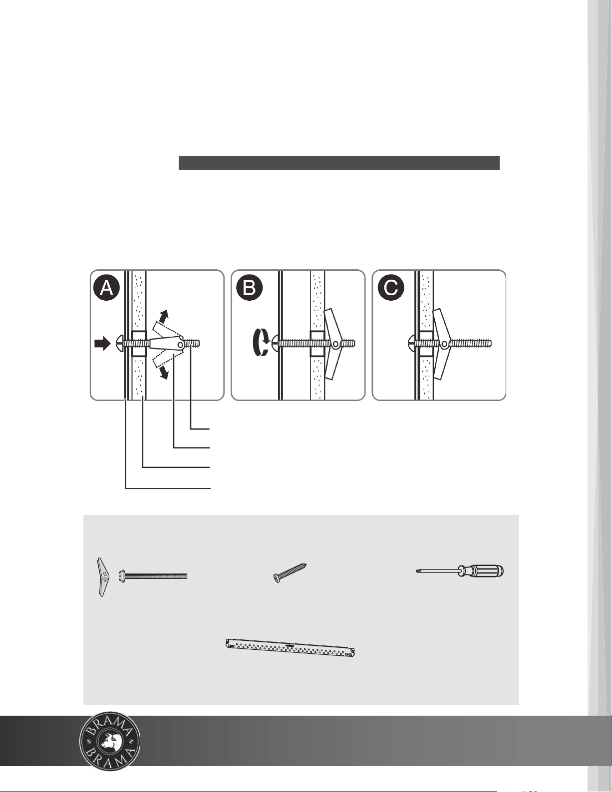
Mounting plate
Wall
Toggle wing
Toggle bolt
You’ll need:
Wood screws
Mounting plate (Qty. 1)
(ships attached to microwave)
Toggle bolts
Phillips screwdrivers
5 Insert wood screw(s) through the mounting plate and into the
hole(s) drilled in the stud(s), then tighten both the wood
screw(s) and toggle bolt(s) with a Phillips screwdriver to mount
the plate. Make sure that the plate is
centered before tightening fully.
Caution
Be careful to avoid pinching your fingers
between the back of the mounting plate
and the wall.
16
WWW.VINOTEMP.COM
Step 5: Option A - Preparing the top cabinet
Notes
If the top cabinet template is damaged or unusable, see “Top cabinet template
dimensions” on page 41 for dimensions.
You need to drill holes for the top support screws, a hole large enough for the power
cord to fit through, and a cutout large enough for the exhaust adapter.
1 Turn off the power to the outlet in the cabinet.
2 Remove everything from the cabinet.
3 Trim the Top Cabinet Template along the dotted line.
4 If the bottom of your cabinet is recessed and the template is too large, trim the edges
to fit. Your template should
fit snugly inside the space with no overhang.
Note
• Make sure that you keep the left and right sides even. For example, if you need
to
trim the sides by 1", cut 1/2" from the left side and 1/2" from the right side.
• Some cabinets have a small bracket or glue block between the overhang
and
the underside of the cabinet bottom. Cut the template to fit around these so it
lies flat on the bottom of the cabinet.
5 To position the Top Cabinet Template:
• Align the center line on the template with the center line that you drew on
the wall.
• Align the back edge of the template to the rear wall (smooth or flat bottom
cabinets) or to the back of the recess (recessed cabinets) to mak
e sure that
the holes cut into the upper cabinet align with the holes in the top of the
microwave.
6 Tape the template to the bottom of the cabinet.
7 Drill ½" holes through the template at points A, B, and C.
Center line
8 Cut a 2" diameter hole at point D for the power cord.
9 Cut out the shaded area G through the cabinet bottom.
CAUTION
Wear safety goggles when
drilling holes in the cabi-
net bottom.
17
732 South Racetrack Road, Henderson, Nevada 89015
info@vinotemp.com
10 If you have recessed cabinets:
• Make two filler blocks out of scrap wood pieces the size of shaded areas H.
They must be as thick as the
depth of the cabinet recess.
• Drill 5/8" holes in the filler blocks to align with points A and B.
11 Remove the template.
Filler blocks
You’ll need:
Top Cabinet Template
Electric drill with 1/2” and 5/8”
bits
Duct tape
Scissors
(recessed cabinets only)
Safety goggles
Saw
(saber, hole, or keyhole)
Ruler or tape measure
Filler blocks or scrap wood pieces
(for recessed cabinets only)
• Align the blocks with the corresponding holes in the cabinet. They
should be at the same level as the bottom edge of the cabinet frame.
18
WWW.VINOTEMP.COM
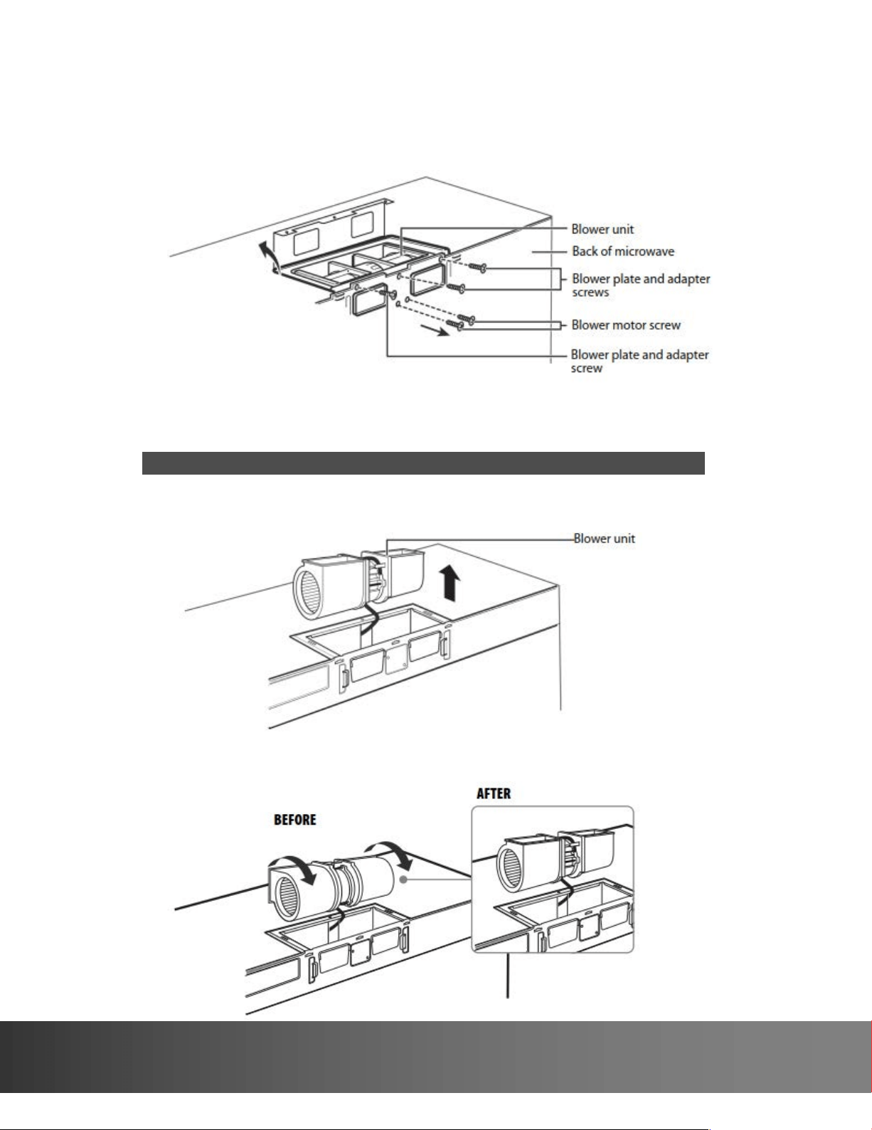
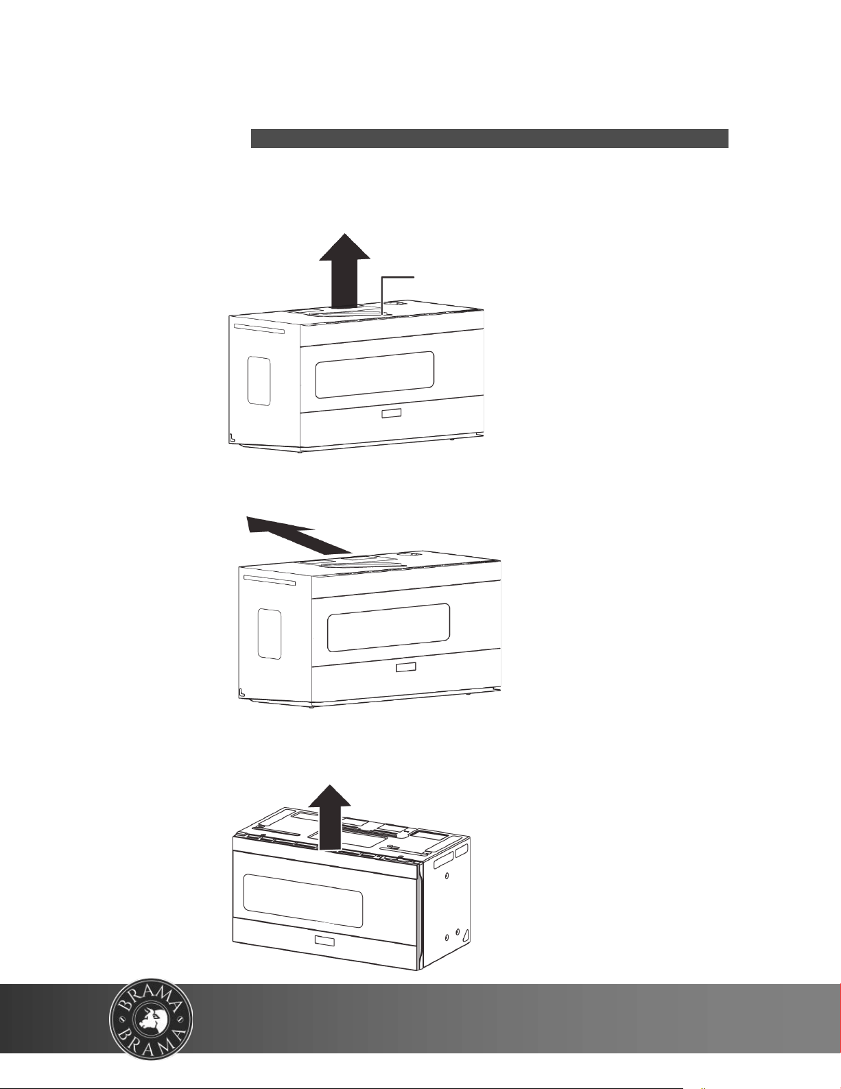
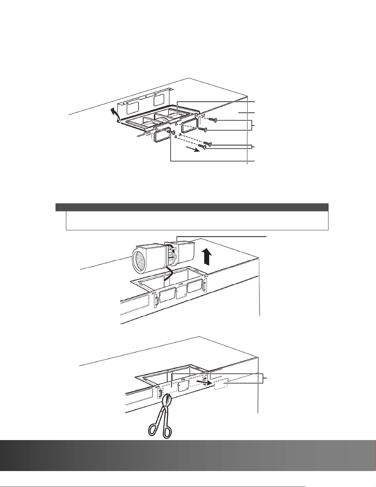
Step 6: Option A - Adapt the microwave blower for
outside top exhaust
1 Remove and save the five screws that hold the blower unit in the
microwave.
2 Carefully pull out the
blower unit. The wires will extend far enough
to let you adjust the blower unit. Do not disconnect the wires.
Warning
Do not pull or stretch the blower unit wiring. Make sure that the wires
are not pinched.
3 Turn the blower unit 90° so that the fan blade openings are facing out
the top of the microwave.
19
732 South Racetrack Road, Henderson, Nevada 89015
info@vinotemp.com
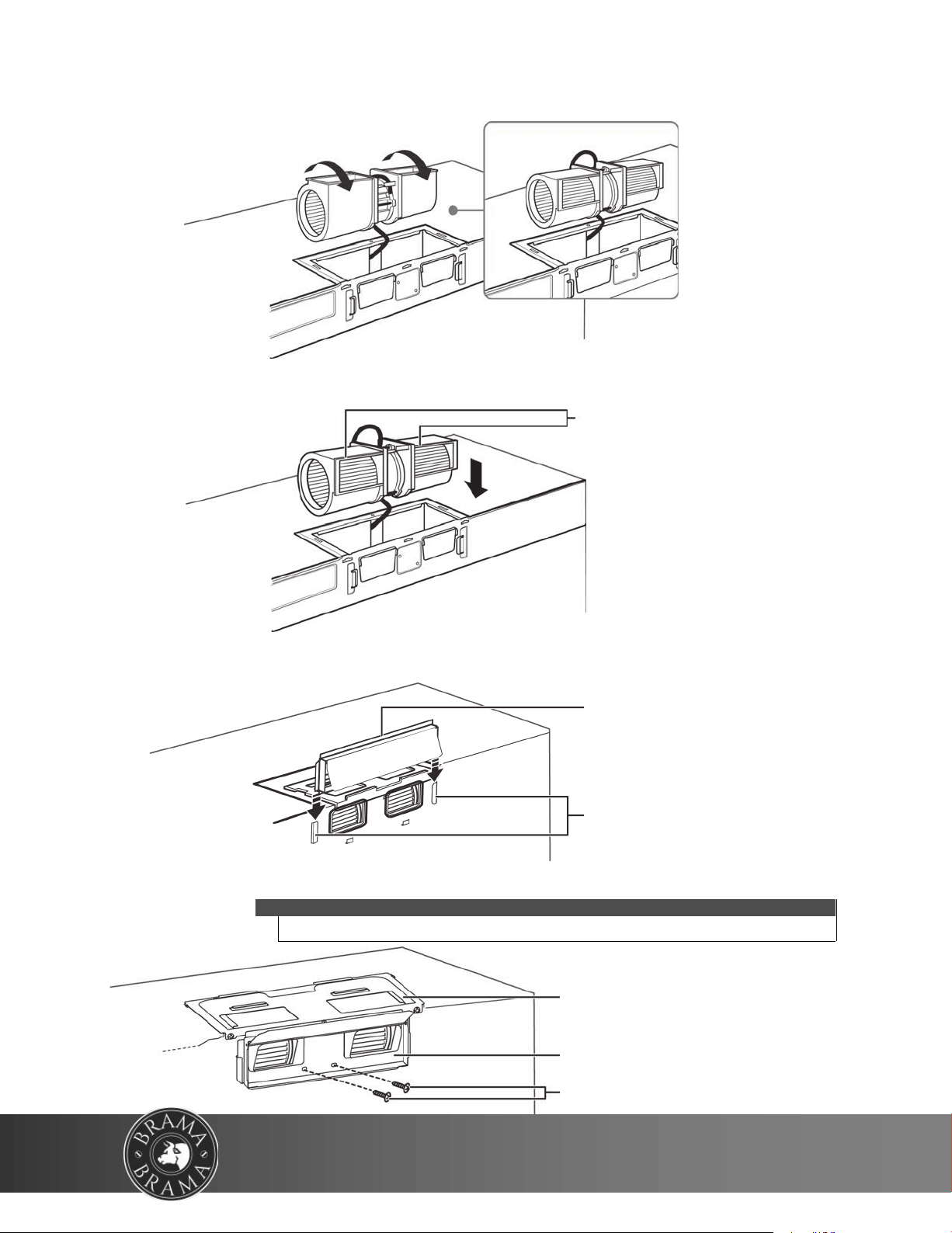
4 Place the blower unit back into the open
ing. The blower unit exhaust
openings should face upwards.
5 Slide the ex
haust adapter into the guides on the top of the microwave
until it is in the locking tabs.
Fan blade openings
facing upwards
Exhaust adapter
Locking tab
Guides
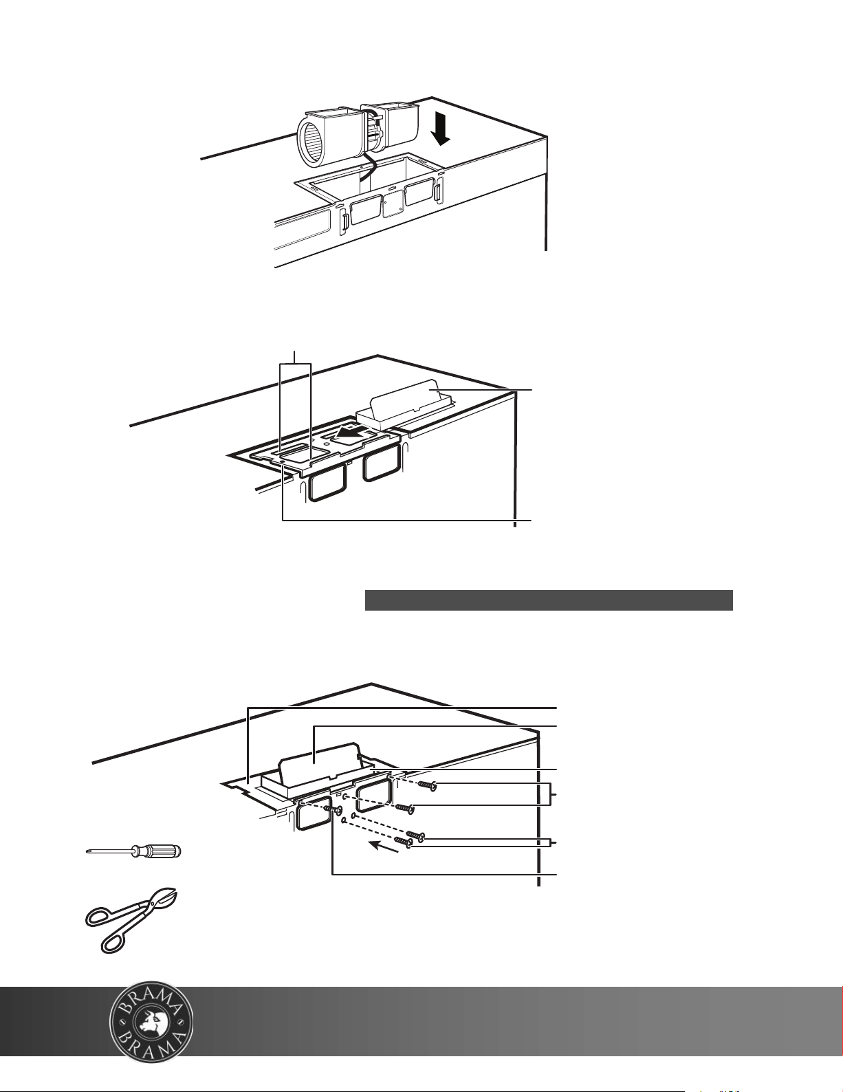
6 Secure the blower unit in the microwave with five of
the screws you previously removed.
Note
Make sure that the damper hinge is at
the top and that it can swing freely.
Exhaust adapter
Blower motor screw
Damper
Blower plate
Blower plate and adapter
screw
Blower plate and adapter
screws
You’ll need:
Phillips screwdrivers
Tin snips
20
WWW.VINOTEMP.COM
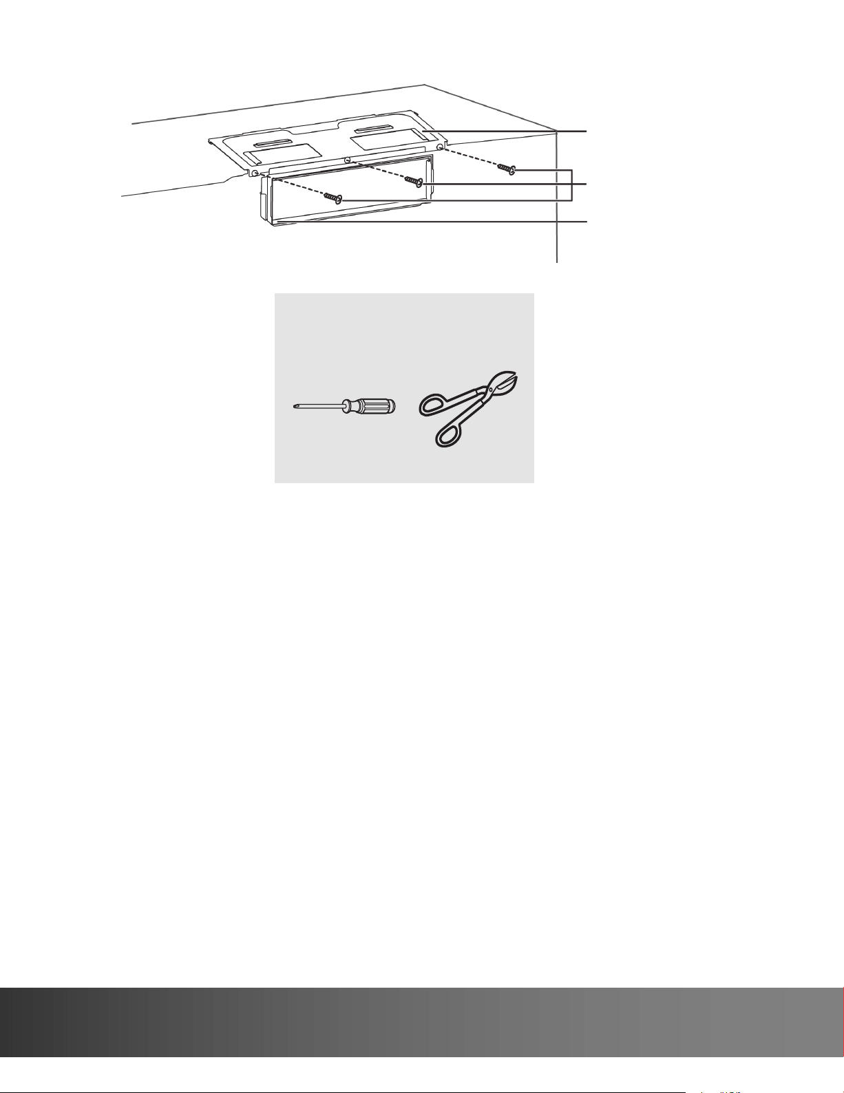
Step 7: Option A - Mount the microwave
CAUTION
• For easier installation and personal safety, we recommend that two people install this
microwave oven.
• Do not grip or use the handle during installation.
• To keep the power cord tight while mounting the microwave oven, thread the
power cord through the hole in the bottom of the cabinet.
1 If your cabinet is metal, insert the nylon grommet into the power cord hole to prevent
cutting the cord.
2 Lift the microwave, tilt it forward, and hook the slots on the back bottom edge onto the
four lower tabs of the mounting plate. Rotate the front of the microwave up against the bot-
tom of the cabinet.
Note
• We recommend using filler blocks if the front of the cabinet hangs below the cabinet’s
bottom shelf.
• If filler blocks are not used, damage may occur from over-tightening the screws.
Thread the power cord through the cable
hole in the top cabinet. Keep it tight
throughout steps 1-2.
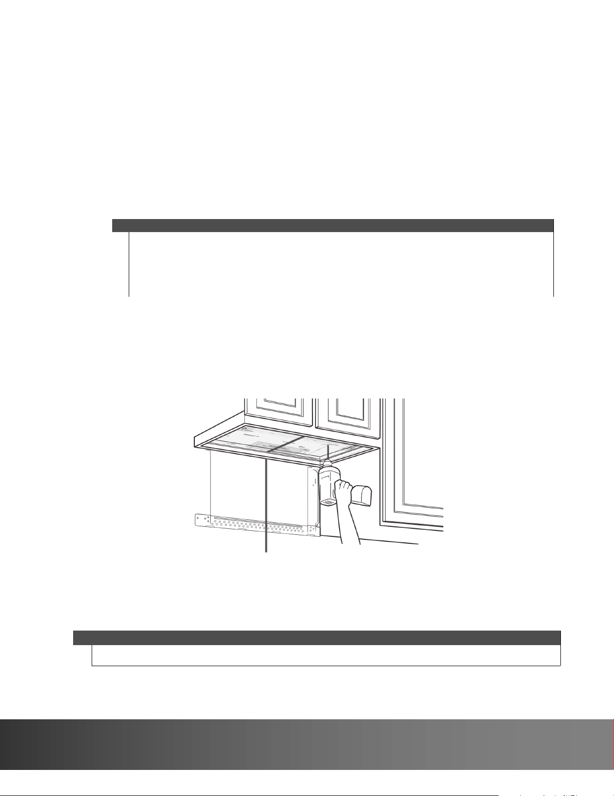
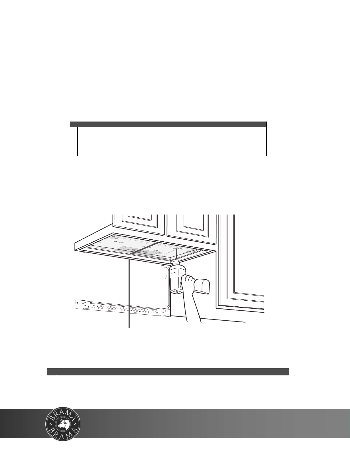
3 T
o temporarily hold the microwave in place, insert a self-aligning machine
screw through the top-center cabinet hole and rotate the screw at least
two full turns (it will be fully tightened later).
CAUTION
Be sure to keep the power cord tight. Do not pinch the cord, especially when
mounting flush to the bottom of the cabinet.
Front of cabinet
Bottom of cabinet
Filler block (optional)
Self-aligning machine screw
Top of microwave
Equivalent to depth of cabinet recess
4 To attach the microwave oven to
the top cabinet, insert two self-aligning
machine screws through the holes you
drilled in the bottom of the cabinet.
Turn each screw at least two full turns
(they will be fully tightened later).
21
732 South Racetrack Road, Henderson, Nevada 89015
info@vinotemp.com
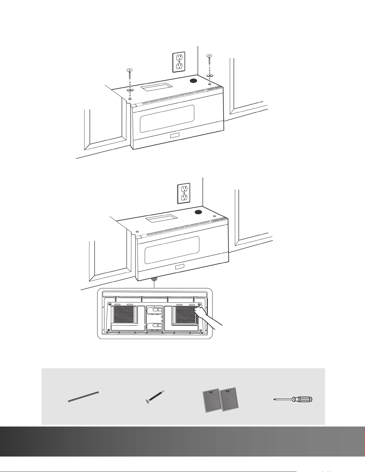
5 While holding t
he microwave up against the wall and cabinet, fully tighten
the top-center machine screw, then fully tighten the outer two screws.
6 Fit the two grease filters into the openings underneath
your microwave.
BOTTOM
You’ll need:
Nylon grommet
(for metal cabinets)
Self-aligning machine
screws
Grease filters
Phillips screwdrivers
22
WWW.VINOTEMP.COM
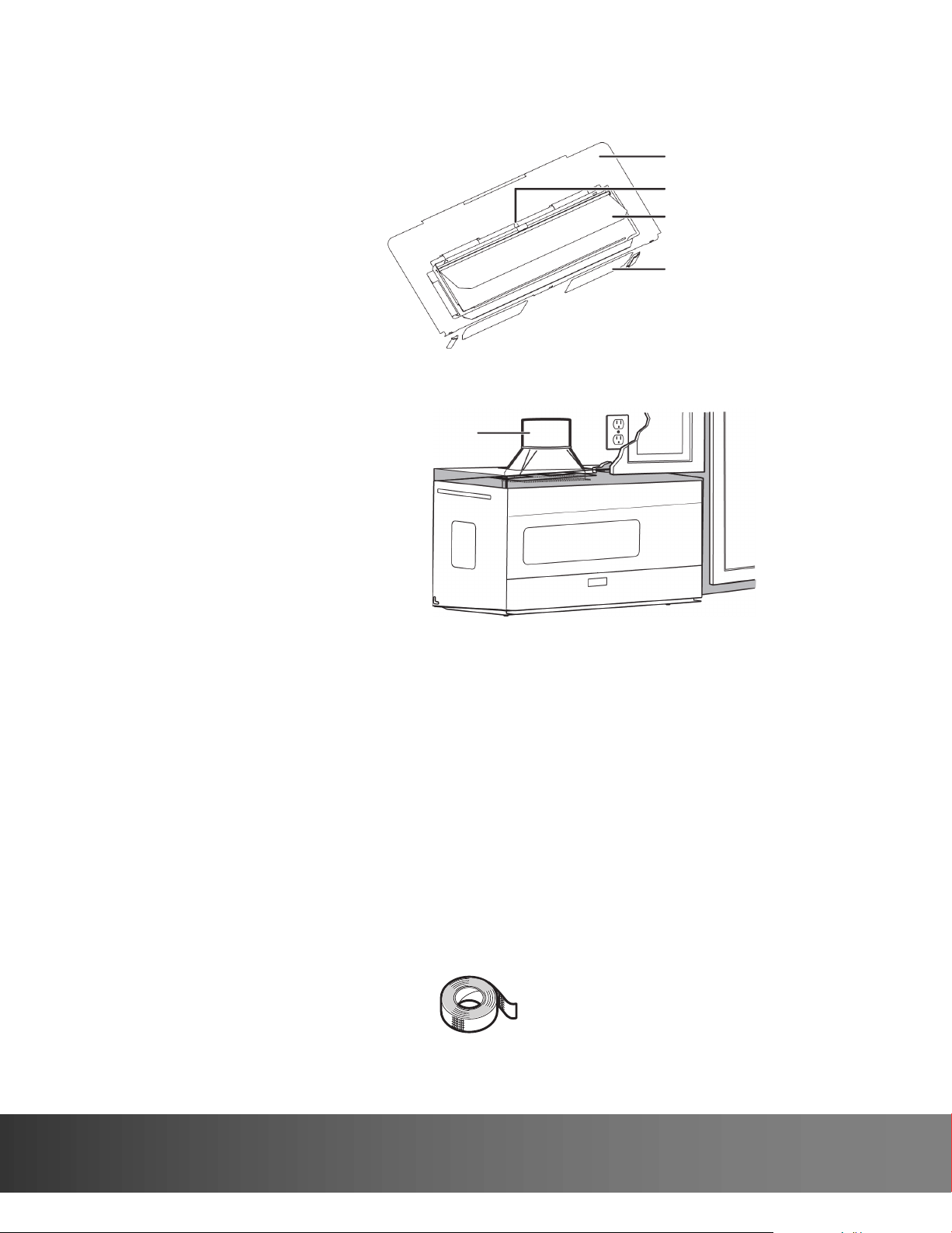
Step 8: Option A - Connecting ductwork
1 Open the cabinet and slide the exhaust adapter front-to-back or side-to-side to adjust.
2 Extend the house duct down to connect to the exhaust adapter.
3 Seal the exhaust duct joints with duct tape.
4 You’re finished! Skip to “Before using your microwave” on page 40.
Blower plate
Exhuast adapter
Damper
Back of microwave
House duct
You’ll need:
Duct tape
23
732 South Racetrack Road, Henderson, Nevada 89015
info@vinotemp.com
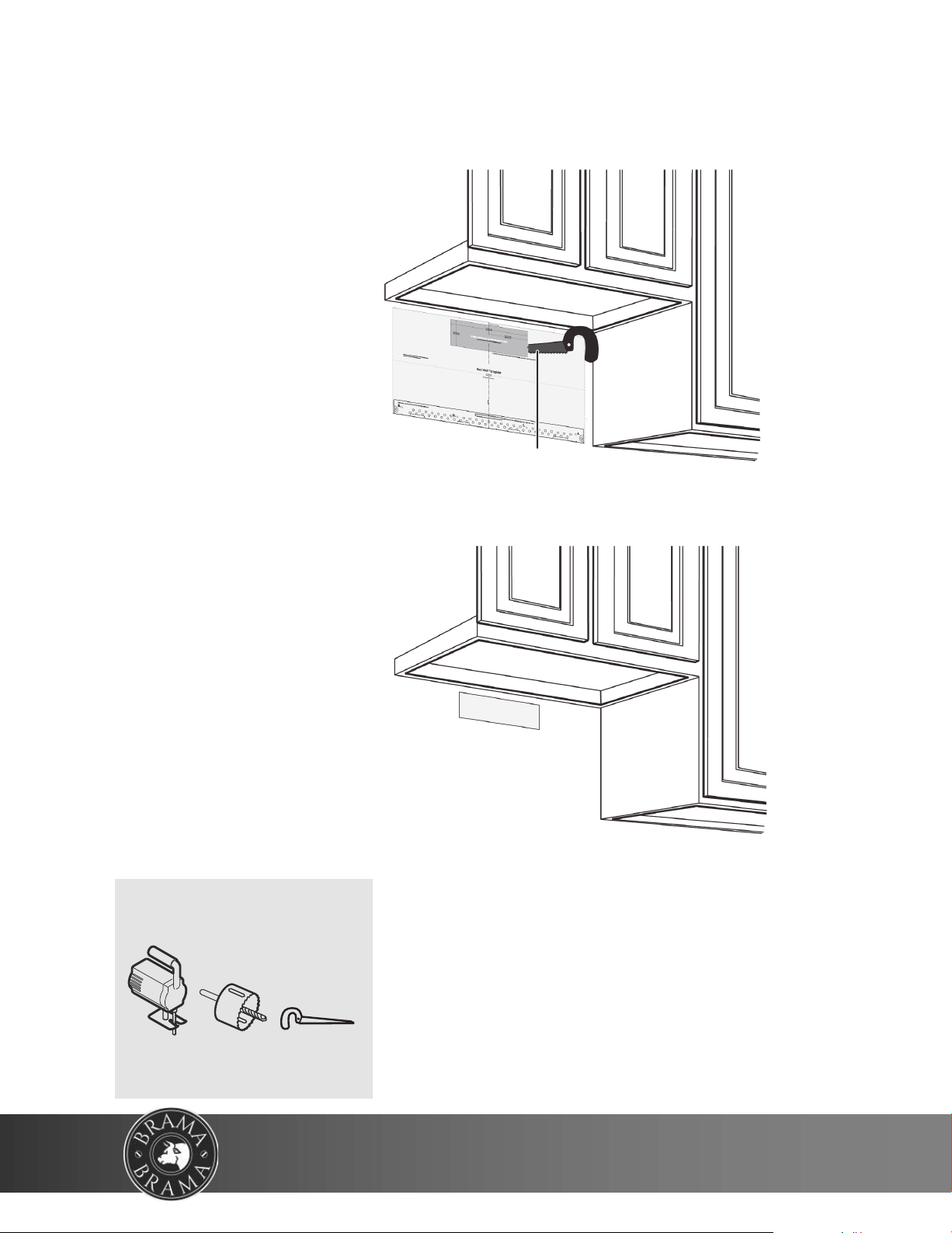
Step 4: Option B - Cutting a vent opening
1 Use a saber or keyhole saw to cut out the shaded area through the rear wall.
2 Remove the rear wall template.
Saw
You’ll need:
Saw
(saber, hole, or keyhole)
24
WWW.VINOTEMP.COM
1 Remove the rear wall template.
2 Remove the mount
ing plate from the back of your microwave using a Phillips screwdriver.
3 Insert the toggle bolt(s) through the front of the mounting plate into the hole(s) that
are not going into a stud,
and then attach the toggle wings ¾" onto each bolt. Hold
your mounting plate up to holes in your wall to identify the correct position.
4 Place the mounting plate against the wall and insert the toggle wings into the
holes you drilled in the drywall. Pull the mounting plate away from the wall to
help tighten the toggle wings.
Note
The top of the mounting plate is indicated with an ar-
row. The mounting plate’s hooks are on the front.
Note: Depending on
your stud locations,
your installation may
look different. You
should insert toggle
bolts into drywall and
wood screws into studs.
Bolt
Mounting plate
Wing
Step 5: Option B - A
ttach the mounting plate to the wall
25
732 South Racetrack Road, Henderson, Nevada 89015
info@vinotemp.com
5 Insert wood screw(s) through the mounting plate and into the hole(s) drilled in the
stud(s), then tighten both the wood screw(s) and toggle bolt(s) with a Phillips
screwdriver to mount the plate. Make sure that the plate is
centered before tightening fully.
Caution
Be careful to avoid pinching your fingers between the back
of the mounting plate and the wall.
Mounting plate
Wall
Toggle wing
Toggle bolt
You’ll need:
Wood screws
Mounting plate (Qty. 1)
(ships attached to microwave)
Phillips screwdrivers
Toggle bolts
26
WWW.VINOTEMP.COM
Step 6: Option B - Preparing the top cabinet
You need to drill holes for the top support screws and a hole large
enough for the power cord to fit through.
1 Turn off the power to the outlet in the cabinet.
2 Remove everything from the cabinet.
3 Trim the Top Cabinet Template along the dotted line.
4 If the bottom of your cabinet is recessed and the template is too large,
trim the edges to fit. Your template should fit snugly inside the space with
no overhang.
Note
• Make sure that you keep the left and right sides even. For example, if you need to
trim the sides by 1", cut 1/2" from the left side and 1/2" from the right side.
• Some cabinets have a small bracket or glue block between the overhang and the
underside of the cabinet bottom. Cut the template to fit around these so it lies flat
on the bottom of the cabinet.
5 T
o position the Top Cabinet Template:
• Align the center line on the template with the center line that you drew on the wall.
• Align the back edge of the template to the rear wall (smooth or flat
bottom cabinets)
or to the back of the recess (recessed cabinets) to make sure that the holes cut into
the upper cabinet align with the holes in the top of the microwave.
Center line
6 Tape the template to the bottom of the cabinet.
7 Drill ½" holes through the template at points A, B, and C.
8 Cut a 2" diameter hole at point D for the power cord.
CAUTION
Wear safety goggles when drilling holes in the cabinet bottom.
27
732 South Racetrack Road, Henderson, Nevada 89015
info@vinotemp.com
9 If you have recessed cabinets:
• Make two filler blocks out of scrap wood pieces the size of shaded areas H.
They must be as thick as the depth of the cabinet recess.
• Drill 5/8" holes in the filler blocks to align with points A and B.
Filler blocks
• Align the blocks with the corresponding holes in the cabinet. They
should be at the same level as the bottom edge of the cabinet frame.
10 Remove the template.
You’ll need:
Top Cabinet Template
Electric drill with 1/2” and 5/8”
bits
Duct tape
Scissors
(recessed cabinets only)
Safety goggles
Saw
(saber, hole, or keyhole)
Ruler or tape measure
Filler blocks or scrap wood pieces
(for recessed cabinets only)
28
WWW.VINOTEMP.COM
Step 7: Option B - Adapt the microwave blower for outside
back exhaust
1 Remove and save the five screws that hold the blower unit in the microwave.
2 Carefully pull out the blower unit. The wires will extend far enough to let you
adjust the blower unit. Do not disconnect the wires.
Blower plate and adapter
screws
Blower motor screw
Back of microwave
Blower unit
Blower plate and adapter
screw
Warning
Do not pull or stretch the blower unit wiring. Make sure that the wires are not
pinched.
3 Cut out the vent holes with tin snips.
Blower unit
Vent hole covers
29
732 South Racetrack Road, Henderson, Nevada 89015
info@vinotemp.com
4 Turn the blower unit 180° so that the fan blade openings are facing out the back of the microwave.
5 Place the blower unit back into the opening. The blower unit exhaust openings should match the exhaust
openings on back of the microwave.
6 Slide the exhaust adapter into the guides on the back of the microwave and push in until it is aligned with the
blower motor screw holes, then secure with the blower motor screws.
7 Secure the blower unit in the microwave with two of the screws you previously removed.
Note
Make sure that the damper hinge is at the top and that it can swing freely.
BEFORE
AFTER
Fan blade openings facing the
back
Exhaust adapter
Guides
Blower motor screw
Exhaust adapter
Blower plate
30
WWW.VINOTEMP.COM
8 Secure the blower plate and exhaust adapter with the remaining screws you removed previously.
Blower plate and adapter
screws
Exhaust adapter
Blower plate
You’ll need:
Phillips screwdrivers
Tin snips
31
732 South Racetrack Road, Henderson, Nevada 89015
info@vinotemp.com
Step 8: Option B - Mount the microwave
CAUTION
• For easier installation and personal safety, we recommend that two people install
this microwave oven.
• Do not grip or use the handle during installation.
• To keep the power cord tight while mounting the microwave oven, thread the
power cord through the hole in the bottom of the top cabinet.
1 If your cabinet is metal, insert the nylon grommet into the power cord hole to prevent
cutting the cord.
2 Lift the microwave, tilt it forward, and hook the slots on the back bottom edge onto the four
lower tabs of the mounting plate. Rotate the front of the microwave up against the bottom of
the cabinet.
Note
• We recomend using filler blocks if the front of the cabinet hangs below the
cabinet’s bottom shelf.
• If filler blocks are not used, damage may occur from over-tightening the screws.
Thread the power cord through the cable
hole in the top cabinet. Keep it tight
throughout steps 1-2.
3 T
o temporarily hold the microwave in place, insert a self-aligning machine
screw through the top-center cabinet hole and rotate the screw at least
two full turns (it will be fully tightened later).
CAUTION
Be sure to keep the power cord tight. Do not pinch the cord, espe-
cially when mounting flush to the bottom of the cabinet.
Front of cabinet
Bottom of cabinet
Filler block (optional)
Self-aligning machine screw
Top of microwave
Equivalent to depth of cabinet recess
4 To attach the microwave oven to the top cabinet, insert two self-aligning machine screws
through the holes you drilled in the bottom of the cabinet. Turn each screw at least two full
turns (they will be fully tightened later).
32
WWW.VINOTEMP.COM
5 While holding the microwave up against the wall and cabinet, fully tighten the
top-center machine screw, then fully tighten the outer two screws.
6 Fit the two grease filters into the openings underneath your microwave.
7 You’re finished! See “Before using your microwave” on page 40
BOTTOM
You’ll need:
Nylon grommet
(for metal cabinets)
Self-aligning machine
screws
Grease filters
Phillips screwdrivers
33
732 South Racetrack Road, Henderson, Nevada 89015
info@vinotemp.com
Step 4: Option C - Attach the mounting plate to the wall
Note: Depending on
your stud locations, your
installation may look
different. You should
insert toggle bolts into
drywall and wood screws
into studs.
1 Remove the rear wall template.
2 Remove the mounting plate from the back of your microwave using a Phillips screwdriver.
3 Insert the toggle bolt(s) through the front of the mounting plate into the hole(s) that are not going into a stud,
and then attach the toggle wings ¾" onto each bolt. Hold your mounting plate up to holes in your wall to
identify the correct position.
Note
The top of the mounting plate is indicated with an arrow. The mounting plate’s
hooks are on the front.
Bolt
Wing
Mounting plate
4 Place the mounting plate against the wall and insert the toggle wings into the holes
you drilled in the drywall. Pull the mounting plate away from the wall to help tighten
the toggle wings.
34
WWW.VINOTEMP.COM
5 Insert wood screw(s) through the mounting plate and into the hole(s) drilled in the stud(s), then tighten both the
wood screw(s) and toggle bolt(s) with a Phillips screwdriver to mount the plate. Make sure that the plate is
centered before tightening fully.
Caution
Be careful to avoid pinching your fingers between the back of the mounting plate
and the wall.
Mounting plate
Wall
Toggle wing
Toggle bolt
You’ll need:
Wood screws
Mounting plate (Qty. 1)
(ships attached to microwave)
Phillips screwdrivers
Toggle bolts
35
732 South Racetrack Road, Henderson, Nevada 89015
info@vinotemp.com
Step 5: Option C - Pr
eparing the top cabinet
You need to drill holes for the top support screws and a hole large enough
for the power cord to fit through.
1 Turn off the power to the outlet in the cabinet.
2 Remove everything from the cabinet.
3 Trim the Top Cabinet Template along the dotted line.
4 If the bottom of your cabinet is recessed and the template is too large, trim
the edges to fit. Your template should
fit snugly inside the space with no overhang.
Note
• Make sure that you keep the left and right sides even. For example, if you need to
trim the sides by 1", cut 1/2" from the left side and 1/2" from the right side.
• Some cabinets have a small bracket or glue block between the overhang and the
underside of the cabinet bottom. Cut the template to fit around these so it lies flat
on the bottom of the cabinet.
5 To position the Top Cabinet Template:
• Align the center line on the template with the center line that you drew on the wall.
• Align the back edge of the template to the rear wall (smooth or flat bottom cabinets)
or to the back of the recess (recessed cabinets) to make sure that the holes cut into
the upper cabinet align with the holes in the top of the microwave.
Center line
6 Tape the template to the bot
tom of the cabinet.
7 Drill ½" holes through the template at points A, B, and C.
8 Cut a 2" diameter hole at point D f
or the power cord.
CAUTION
Wear safety goggles when drilling holes in the cabinet bottom.
36
WWW.VINOTEMP.COM
9 If you hav
e recessed cabinets:
• Make two filler blocks out of scrap wood pieces the size of shaded areas
H. They must be as thick as the
depth of the cabinet recess.
• Drill 5/8" holes in the filler blocks to align with points A and B.
•
Align the block
s with the corresponding hole
s in the cabinet. They
should be at the same level as t
he bottom edge of the cabinet frame.
10 Remove the template.
Filler blocks
You’ll need:
Electric drill with 1/2” and 5/8”
bits
Duct tape
Scissors
(recessed cabinets only)
Safety goggles
Saw
(saber, hole, or keyhole)
Ruler or tape measure
Filler blocks or scrap wood pieces
(for recessed cabinets only)
Top Cabinet Template
37
732 South Racetrack Road, Henderson, Nevada 89015
info@vinotemp.com

Step 6: Option C - Mount the microwave
CAUTION
• For easier installation and personal safety, we recommend that two people install
this microwave oven.
• Do not grip or use the handle during installation.
• To keep the power cord tight while mounting the microwave oven, thread the
power cord through the hole in bottom of the top cabinet.
1 If your cabinet is metal, insert the nylon grommet into the power cord hole to prevent
cutting the cord.
2 Lift the microwave, tilt it forward, and hook the slots on the back bottom edge onto the
four lower tabs of the mounting plate. Rotate the front of the microwave up against the bot-
tom of the cabinet.
Note
• We recomend using filler blocks if the front of the cabinet hangs below the
cabinet’s bottom shelf.
• If filler blocks are not used, damage may occur from over-tightening the screws.
Thread the power cord through the cable
hole in the top cabinet. Keep it tight
throughout steps 1-2.
3 To temporarily hold the microwave in place, insert a self-aligning machine screw
through the top-center cabinet hole and rotate the screw at least two full turns (it
will be fully tightened later).
CAUTION
Be sure to keep the power cord tight. Do not pinch the cord, especially when
mounting flush to the bottom of the cabinet.
Front of cabinet
Bottom of cabinet
Filler block (optional)
Self-aligning machine screw
Top of microwave
Equivalent to depth of cabinet recess
4 To attach the microwave oven to the top cabinet, insert two self-aligning machine
screws through the holes you drilled in the bottom of the cabinet. Turn each screw at least
two full turns (they will be fully tightened later).
38
WWW.VINOTEMP.COM
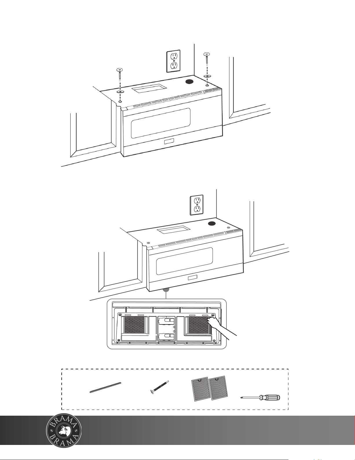
5 While holdin
g the microwave up against the wall and cabinet, fully tighten
the top-center machine screw, then fully tighten the outer two screws.
6 Fit the two grease filters into the openings underneath your microwave.
7 You’re finished! Skip to “Before using your microwave” on page 40.
BOTTOM
You’ll need:
Nylon grommet
(for metal cabinets)
Self-aligning machine
screws
Grease filters
Phillips screwdrivers
39
732 South Racetrack Road, Henderson, Nevada 89015
info@vinotemp.com
Before using your microwave
1 Make sure that all packing material has been removed from the microwave.
2 Install the turntable and ring inside your microwave. See your User Guide for
more information.
3 Plug the power cord into a dedicated 20 amp electrical outlet.
4 Turn your circuit breaker back on.
Specifications
Note
Keep these installation instructions for the local inspector’s use.
Model
Rated voltage 120V / 60 Hz
Rated input power 1550W
Rated output power 1000W
Microwave capacity 1.6 cu. ft.
Turntable diameter 13.5 in. (34.5 cm)
External dimensions (WxDxH) 31.3 x 15 x 16.4 in. (79.5 × 38.2 × 41. 7 cm)
Internal dimensions (WxDxH) 20.24 x 14.41 x 9.25 (51.4 × 36.6 × 23. 5 cm)
Certifications UL approved
Power cord length 3.3 ft. (1 m)
Net weight 56 lbs. (25.4 kg)
EM044K6BB(BR-MW OH16-S)
40
WWW.VINOTEMP.COM

Template dimensions
Rear wall template dimensions
If your rear wall template is unusable, drill using the dimensions below.
16.5 in.
(41.9 cm)
30 in.
(76.2 cm)
41
732 South Racetrack Road, Henderson, Nevada 89015
info@vinotemp.com
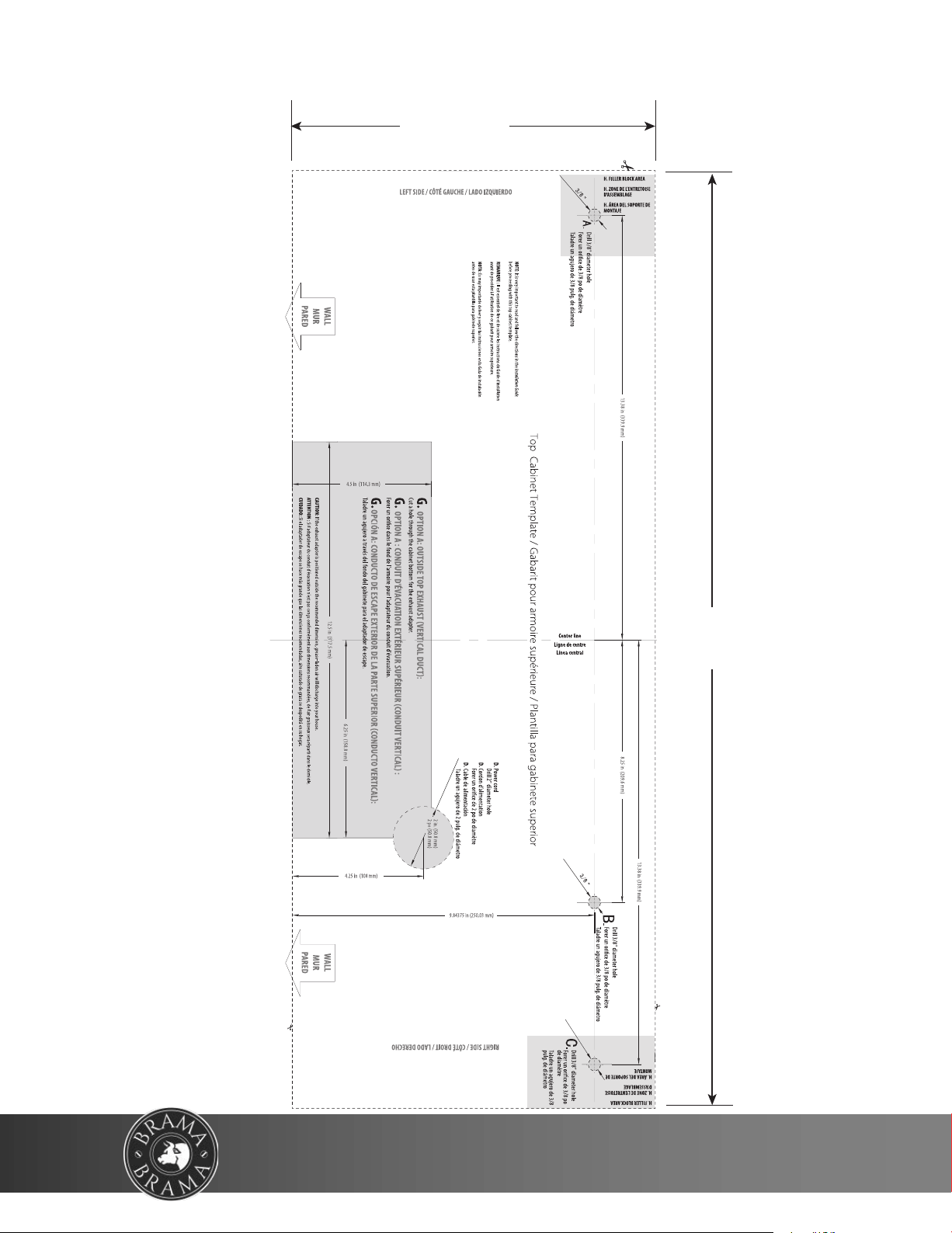
Top cabinet template dimensions
If your top cabinet template is unusable, drill/cut using the dimensions below.
11.8 in.
(30.0 cm)
29.5 in.
(75 cm)
42
WWW.VINOTEMP.COM

43
732 South Racetrack Road, Henderson, Nevada 89015
info@vinotemp.com
TERMS & CONDITIONS
Shipping/Delivery fees are the responsibility of the Purchaser. Seller is not responsible for the
carrier’s missed/Non delivery for any reason. Delivery is curbside. Optional upgrades in delivery
service is an additional fee. If upgraded delivery service cannot be performed properly, Purchaser
agrees to accept delivery curbside and the difference in upgraded cost will not be refunded. If item
with free shipping/freight is canceled in transit, a charge of 25% of the price of the unit/s plus freight
costs both ways will be charged. All damages must be noted at time of delivery on BOL and Seller
to be notified within 48 hours of delivery of such damage. Purchaser acknowledges if cancelation is
authorized by Seller, a 35% restocking fee and freight both ways will be charged. No cancelation or
refund on made-to- order products. If an order has been placed and production has not started,
cancellation fee of 15% of total amount will be charged. Cancelled orders paid by Credit Card will
have an additional fee of 3% deducted from the total refund. Refurbished units are sold as is.
Purchaser assumes risks to the quality and performance of goods and assumes the costs of all
necessary service or repair not covered herein.
(Box here for check mark) Accept Terms & Conditions
Vinotemp International Corp. (“Seller”) and the person or entity that acquires these goods from Seller
(“Purchaser”) hereby fully agrees to the following terms and conditions of the sale:
Shipping/Delivery fees are the responsibility of the Purchaser whether freight prepaid or freight
collect. Seller assumes responsibility for the goods sold to the Purchaser until the goods have
reached Purchaser’s delivery address (FOB Destination) and the delivery receipt is signed clear.
Seller is not responsible for the carrier’s late delivery, missed delivery, unpaved roads, remote
locations, stairs, elevators, narrow door openings and other such issues in attempting to fit or deliver
the goods into the Purchaser’s location. Delivery to remote locations may require additional fees.
Remote location may be defined at the discretion of the carrier as more or less than 50 miles from
the nearest major city. Purchaser assumes all responsibility for additional costs related to freight
such as access, measurement, installation, hookup, wiring, moving and storage of the goods, flight
of stairs, carrier’s inability to safely and/or adequately deliver, inability to use the building elevator to
lift the goods, narrow openings, along with any additional costs to deliver or redeliver the product
properly. Make sure to review access to the property and size of the product ordered. The
transportation of all goods is subject to the terms and conditions which the carrier imposes on
Purchaser. Installation is the responsibility of the Purchaser. If white glove delivery was ordered and
cannot be performed properly, or access is hindered in any way, Purchaser agrees to accept delivery
curbside (delivery service cannot be refunded). If Purchaser will-calls or pays for their own freight
responsibility transfers to the Purchaser when the Purchaser or Purchasers freight company picks
up the unit from Seller. Freight quoted are either curbside, threshold or white glove. Standard white
glove delivery is main floor, easy access and NO STAIRS, Doors, aligned feet attached (if necessary)
and removal of packaging, additional fees for additional requests. Each service has a different rate
and will require additional fees. If freight is not charged (Free Shipping or Freight Included) and the
order is cancelled after shipping, a freight charge of 25% of the cost of the unit, each direction will
be charged. Item swap outs are arranged as curbside delivery and pickup unless noted otherwise.
There is no white glove service for returns. Approved returns must have original and/or proper
packaging. Swap-outs (Delivery and Pick up are at the same time) Original unit must be packed and
ready for carrier pick up at time of delivery of new unit. Packaging of old unit must be adequate for
shipping, not oversized or on a pallet if unit was not originally delivered on a pallet. Carrier will not
drop off new unit if the original unit is not ready. If the carrier has to make a second attempt, customer
will be subject to additional charges for the attempted delivery and for any packaging issues.
Deliveries include ONE attempt by the shipping company to deliver the product to the consumer. If

44
WWW.VINOTEMP.COM
!
!
for any reason the customer is unavailable to accept the order and the product is undeliverable under
any circumstances, the customer will be responsible for any extra shipping and handling charges.
We are a manufacturer not a shipping company, deliveries are done by a 3rd party service. Email us
USA (excluding Alaska, Puerto Rico, Hawaii), cost is additional please email in[email protected] for
a quote.
California Proposition 65 Warning: The products sold on this ecommerce website and to the public
may contain chemicals and other substances known to the State of California to cause cancer and
birth defects and other reproductive harm.
Totes made of vinyl, imitation leather, and/or leather material contain lead and/or other substances
that are known to the State of California to cause cancer, birth defects and other reproductive harm.
Microfiber “Plastic microfiber” means a small synthetic particle that is fibrous in shape, less than 5
millimeters in length, and is released into water through the regular washing of textiles made from
synthetic material.
Composite wood: May contain formaldehyde.
Galvanized metal and some of its constituents contain lead and/or other substances that are known
to the State of California to cause cancer, birth defects and other reproductive harm.
Products made of vinyl contain lead, Diethyl Hexyl Phthalate (DEHP), and/or other substances that
are known to the State of California to cause cancer, birth defects and other reproductive harm.
Acrylic may contain Acrylic Acid and/or other substances that are known to the State of California to
cause cancer, birth defects, and other reproductive harm.
Appliances may contain tin or lead in either the paint or the controllers, and/or other substances that
are known to the State of California to cause cancer, birth defects, and other reproductive harm.
Our barware items may contain plastic, acrylic, enamel, crystal, metal and/or other substances that
are known to the State of California to cause cancer, birth defects, and other reproductive harm.
Appliances may contain Tin, Lead or Nickel
Damage: All damages must be noted at time of delivery. If a bill is signed that there is no damage,
buyer accepts delivery as free and clear. Any claim for damages of the goods, when FOB
Destination, that incurred during shipment by the carrier are insured and handled directly with the
carrier by the Seller if noted on the receipt and notified within 48 hours of delivery. OPEN AND
INSPECT YOUR DELIVERY. When FOB Destination, if the item is damaged by the freight company,
and Purchaser cancels rather than accepts a replacement, the order can be cancelled by paying for
freight costs both ways and a 35% restocking fee for stocked items. No cancellation or refunds on
custom/made or made to order products. When shipped 3rd Party (FOB Warehouse), Purchaser
assumes all responsibility for delivery, payment of freight and freight claims for damages during
shipment. Manufacture defects will be handled directly with Seller, subject to the limited warranty
below.
Fees: All sales are final. Unless authorized in writing by the Seller, Purchaser may not return the
goods under any circumstance. If Seller agrees in writing to take back stocked goods, there will be
a restocking/service fee that is 35% of the purchase price of the goods and freight both ways (product
must be new, unused, and in original packaging). If Purchaser returns goods claiming that the goods
are defective and goods are found to be in working condition by the Seller, Purchaser is liable for the
cost of freight both ways plus and a service fee that is 35% of the purchase price of the goods. Built
to Order and Custom products are nonreturnable, nonrefundable. Purchaser must notify Seller of
nonconforming goods within 48 hours of receipt, after which time all goods are deemed accepted by
the Purchaser. If an order has been placed and production has not started, cancellation of your order

45
732 South Racetrack Road, Henderson, Nevada 89015
info@vinotemp.com
will be a 15% charge. If Purchaser tenders payment with a check that has insufficient funds (NSF),
a collection fee plus NSF fee of $50 will be added to the invoice, which Purchaser agrees to pay
promptly. If Purchaser puts a stop payment on a check or credit card for any reason, Purchaser
agrees to pay for all costs associated with the Seller’s collection or litigation of such a claim, including,
without limitation, general and special damages, court costs and attorneys’ fees. Finance charges
begin the date of invoice. Title to the goods reverts back to the Seller in the case of nonpayment of
goods or services. All fees and costs to retrieve the product, cost of freight, legal costs, collection
fees and court fees, credit card fees and interest rate of 18% (annual rate) will be the responsibility
of the Purchaser. In a credit card dispute, Purchaser assumes and must immediately pay any “credit
card arbitration” fees and chargeback fees which the credit card companies charge at the time of the
chargeback. Cancelled orders using a Credit Card will have an additional fee of 3% deducted from
the refund. Any disputes not resolved within 30 days from the invoice date will be reported to credit
reporting agencies.
LIMITED WARRANTY: Seller warrants that the goods will be free of defects in materials and
workmanship as follows:
Furniture style (wood) wine cabinets made in the U.S.: all cooling unit parts only for a period of 1
(year) year; cabinetry and labor (uninstalled) for a period of 12 (twelve) Months (Model numbers
“Vino” and “Custom”.
Metal cabinet units (appliances) (compressor) (made in China and Denmark)(Model numbers start
with EL, VT, IL, or EP: parts and labor for cooling system and cabinetry for a period of 12 (twelve)
months.
Thermoelectric Units: 90 (ninety) days (including Wine and Beverage Coolers, Beer Dispensers,
Humidor, Portofino Wood Cellars, and Refrigerators). (Models start with EL, VT, IL or EP). WineMate
and Cellar Tec (WM, Wine Mate or CT)(Wine Cooling Units) Split and Ducted Systems and other
installed cooling units are parts only for 1 year, no labor. Self Contained WineMate Cooling Systems
are 1 year parts, 1 year labor. Removal and reinstallation of cooling units is not included.
Wine Accessories, Racking Systems, Parts and Other miscellaneous items is a 30 day warranty.
Il Romanzo units: Warranty 90 (ninety) days. Replacement part 12 (twelve) months from the date of
sale.
Brama: 1 year warranty from date of purchase.
Non-New Units (Scratch & Dent/Refurbished/Floor Models), warranty for compressor units is 90 days
from your dated invoice and 30 days for thermoelectric units (parts for function only, not cosmetic
defects). These units are refurbished and sold as is; Purchaser assumes risks to the quality and
performance of goods and assumes the costs of all necessary service or repair not covered herein.
Extended warranties via New Leaf may not be purchased on Non-New Units. Delivery is curbside.
Upgrades in delivery will require an additional fee.
Element Grills (via Element Products LLC), grills have a thirty day limited parts warranty on grill
accessories.
If a model is not listed here will have 90 day warranty on parts only if it’s a new item.
Parts and Repairs: Warranty on in-house repairs: 90 days parts and labor for compressor; 30 days
parts and labor for Thermoelectric; Customer is required to put down a labor deposit of $75 for
Thermoelectric units; $150 for compressor based Wine Coolers and $195 for WineMate units which
will be kept if a unit is found to be in good working condition. Customer is responsible for freight costs
to us.
Warranty on parts purchased: 30 days; if part fails within 30 days of purchase, customer is to ship
us back the part; upon inspection, if defective, VT will send replacement part at no charge.

46
WWW.VINOTEMP.COM
!
!
If a purchaser claims a product is “defective” with regards to refrigeration, Purchaser must obtain a
letter from a qualified refrigeration technician at the Purchaser’s cost to verify that the unit was
installed properly, with proper ventilation and the unit is truly malfunctioning due to a manufacturing
defect.
Removal or reinstallation of a unit is not included in warranted costs. Purchaser’s exclusive remedy
is limited at Seller’s option to repair or replace defective part[s] with either new or reconditioned
part[s]. Purchaser is responsible for shipping the unit prepaid to a designated facility and Seller will
pay return shipping charges in the continental United States for items repaired under warranty within
12 (twelve) months from date of sale. The returned unit must be packaged correctly, with enough
protection to ensure the unit is not further damaged. Oversized or lack of packaging is not permitted
and will be refused. Replacement or exchanged units will be returned to Purchaser through curbside
delivery only. Any redelivery fees are the Purchasers responsibility. Since the natural variation in
texture, density, grain, color, tone, and shade of wood is unavoidable; Seller does not guarantee the
texture, color, tone, or shade of the wood: nor does seller guarantee the colorfastness of wood or
against peeling, chipping, cracking, or scratching. Note: Unfinished wood is subject to warping; all
wood surfaces must be sealed before placing cellar into service. Make sure doors are aligned by
reviewing the owner’s manual. Improper repair or placement of the unit will void the warranty. Any
third party repair facility must be preapproved in writing by Seller, before providing replacement parts
under warranty. Change Orders: Custom units already in production that require a change will be
subject to a change order fee.
Storage Fees: When having an item serviced by a Vinotemp service technician at the Vinotemp
facility, Purchaser agrees to pick up their repaired item or make arrangements for return shipping
within a 30 day period once they have been notified by Vinotemp through phone call, email, or letter
that their unit is ready for pick up. If the item remains in the Vinotemp warehouse after 30 days but
no longer than 60 days, the Purchaser will incur additional storage fees of 2%. After 60 days in
storage, the item will become property of Vinotemp. For custom units with deposits: If product is not
picked up or shipped within 60 days of completion, Purchaser deposit is forfeited and product
becomes the property of Vinotemp. Warranty period is from the date of sale (not from shipping,
delivery, nor installation). All completed cabinetry, racking, or other custom work must be picked up
or shipped within a period of 14 days after Vinotemp has notified the Purchaser by phone call, email,
or letter. Any completed cabinetry, racking, or other custom work stored longer than 14 days will
incur an additional monthly storage fee. After 60 days, the product will become property of Vinotemp.
This Limited Warranty does not cover damage due to such things as accident, misuse, abuse,
mishandling, neglect, acts of God, fires, earthquakes, floods, high winds, government, war, riot or
labor trouble, strikes, lockouts, delay of carrier, unauthorized repair, or any other cause beyond the
control of the Seller, whether similar or dissimilar to the foregoing. Seller is not responsible for any
damages caused to Purchaser's property resulting from the goods. This limited warranty applies only
inside the Continental US (Alaska, Puerto Rico, Hawaii and other territories/countries are not
warranted). Purchaser understands and acknowledges that the goods sold here are wine cellars,
cigar humidors, and/or other similar units which house wine or cigars or other items. Purchaser
assumes all risk of using these units, including risk of spoilage, humidity variations, temperature
variations, leaks, fire, water damage, mold, mildew, dryness and similar and any other perils that
might occur. Seller is not responsible for incidental or consequential damages, and there are no
warranties, expressed or implied, which extend beyond the Limited Warranty described above.
Warranty and liability are nontransferable. The implied warranties of merchantability and of fitness
for a particular purpose are hereby expressly disclaimed. Some states do not allow the exclusion of
incidental or consequential damages, or a waiver of the implied warranties of fitness and/or
merchantability, so the above limitations may not apply to you. This warranty gives you specific legal
rights and you may also have other rights which vary from state to state. Seller disclaims any

47
732 South Racetrack Road, Henderson, Nevada 89015
info@vinotemp.com
indemnification for claims of infringement of any intellectual property of protectable nature. In the
event of any dispute between Seller and Purchaser arising out of or relating to these terms and
conditions or to the goods sold generally, Purchaser must first file a written claim with Seller within
ten days of the occurrence giving rise to the claim and wait an additional thirty days for a response
before initiating any legal action. The sale and all terms are subject to Nevada law. Any legal
proceeding arising out of or relating to these terms and conditions or to the goods sold Purchaser
shall bring, solely and exclusively in Clark County. In no event may Purchaser initiate any legal
proceeding more than six months after the occurrence of the event giving rise to the dispute. Seller
may make nonpayment claims until debt is paid in full. Any dispute or claim relating in any way to
these to the Terms and Conditions, the Website, or any products or services sold or distributed by
or through this Website, store, or catalog will be resolved by binding arbitration, rather than in court,
except that you may assert claims in small claims court if your claims qualify. The Federal Arbitration
Act and federal arbitration law apply to the Terms and Conditions. We each agree that any dispute
resolution proceedings will be conducted only on an individual basis and not in a class, consolidated
or representative action. If for any reason a claim proceeds in court rather than in arbitration we each
waive any right to a jury trial. Both parties agree to bring suit in court to enjoin infringement or other
misuse of intellectual property rights.
The above terms and conditions are the only ones governing this transaction and Seller makes no
oral representations of any kind. These Terms and Conditions can only be modified in writing, signed
by both Purchaser and Seller.
SPECIFIC WARRANTY BELOW for SCRATCH & DENT/OPEN BOX/ REFURBISHED/FLOOR
MODELS/ CLOSEOUTS, OVERSTOCK: TERMS AND CONDITIONS OF SALE
Vinotemp (and its brands Element, Wine Mate, Cellar Tec, Apex Wine Racks, Epicureanist Il
Romanzo, Brama(“Seller”) and the person of the entity that acquires these goods from Seller
(“Purchaser”) hereby fully aggress to the following terms and conditions of the sale:
1. Freight: Vinotemp is not a freight, moving or installation company, if Freight is arranged for t
he
Buyer, the Seller assumes no responsibility for the goods sold to the Purchaser once the goods have
le
ft t
he Seller’s premises, including, but not limited to, late delivery by the moving carrier, or for events
caused by any difficulty carrier incurs in attempting to fit the goods into the Purchaser’s place of
business or residence due to the size of the goods or otherwise, such as the disassembly
and
reassembly of the goods. Purchaser assumes all responsibility for delivery, payment of freight, extra
fees, a
ccess, measurement, installation, hook-up, moving and storage of the goods. The
transportation of all goods is subject to the terms and conditions which the moving carrier imposes
on Purchaser
including, but not limited to, additional charges imposed per flight of stairs, and/or
additional charges resulting from the carrier’s inability to safely and/or adequately use the buildi
ng
elevator to lift the goods to an upper floor. Any claim for damages incurred during shipment by the
carrier of the goods are insured
and handled directly with the carrier and must be noted at time of
delivery.
2. All sales are final, and unless authorized in writing by the Seller, Purchaser is not entitled to return
goods, under any circumstances. If Purchaser refuses to accept goods, the Purchaser is liable for
the retu
rn and cost of freight both directions and a restocking/service fee that is 35% of the purchase
price of the goods. Purchaser must notify Seller of non-conforming goods within four days of
delivery, after which time all goods are deemed accepted.
3. If Purchaser tenders payment with a check that has insufficient funds (NSF), or stops payment on
a check or credit card for any reason, Purchaser agrees to pay for all costs associated with the

48
WWW.VINOTEMP.COM
!
!
Seller’s connection or litigation of such a claim, including without limitation extra damages, court
costs, collection fees and attorney’s fees. Finance charges begin the date of invoice. Collection fees
plus NSF fee of $50 will be added to your invoice, which you agree to promptly pay. Title to the goods
does not pass until payment is received in full by Seller and Seller retains a security interest in the
goods until they are paid for in full. If the credit card dispute goes to arbitration, Buyer agrees to pay
for credit card arbitration fees.
4. LIMITED WARRANTY on Non-New Units (Scratch & Dent/Refurbished and Floor Models):
warranty for compressor units is 90 days from your dated invoice and 30 days for thermoelectric
units (parts for function only, not cosmetic defects). These units are refurbished and sold as is;
Purchaser assumes risks to the quality and performance of goods and assumes the costs of all
necessary service or repair not covered herein. Wine Accessories, Racking Systems and other items
not mentioned are not warranted. There is no warranty on parts purchased separately. Removal and
re-installation of unit is not included in warranted labor. Purchaser’s exclusive remedy is limited, at
Seller’s option; to repair or replace defective part[s] with either new or factory reconditioned part[s].
Purchaser is responsible for shipping the unit pre-paid to designated facility and Seller will pay return
shipping charges in the continental United States for items repaired under warranty. Since the natural
variation in texture, density, grain, color, tone and shade of wood is unavoidable; Seller does not
guarantee the texture, color, tone or shade of the wood: nor does seller guarantee the colorfastness
of wood or against peeling, chipping, cracking or scratching. Note: Unfinished wood is subject to
warping; all wood surfaces must be sealed before placing cellar into service. Improper placement of
the unit will void the warranty. By Vinotemp in writing, any 3rd party repair facility must be pre-
approved before providing parts free of charge.
5. Freight: If As-Is unit is shipped including freight and delivery is denied, customer is responsible fo
r
freight to and from buyer. Other costs Buyer is responsible for is storage, repackaging, and attempted
delivery f
ees.
6. Vinotemp does not cover damage due to such things as accident, misuse, abuse, mishandling,
neglect, acts of God, fires, earthquakes, floods, high winds, government, war, riot or labor trouble,
strikes, lockouts, delay of carrier, unauthorized repair, or any other cause beyond the control of the
Seller, whether similar or dissimilar to the foregoing. Seller is not responsible for any damages
caused
to Pur
chaser's property resulting from the good. This limited warranty applies only inside the
Continental US.
(Ala
ska, Puerto Rico and Hawaii are not warranted.)
7. Purchaser understands and acknowledges that the goods sold here are wine coolers, appliances,
cigar humidors, and/or other similar units which may house wine or cigars or other consumables.
Purchaser assumes all risk of using these units, including risk of spoilage, humidity variations,
temperature variations, leaks, fire, water damage, mold, mildew, dryness and similar perils that might
occur.
8.
UNLES
S OTHERWISE PROVIDED BY APPLICABLE LAW, SELLER IS NOT RESPONSIBLE
FOR INCIDENTAL OR CONSEQUENTIAL DAMAGES, AND THERE ARE NO WARRANTIES,
EXPRESS OR IM
PLIED, WHICH EXTEND BEYOND THE DESCRIPTION ON THE FACE
HEREOF; WARRANTY AND LIABILITY ARE NON-TRANSFERABL
E. THE I
MPLIED
WARRANTIES OF MERCHANTABILITY AND OF FITNESS FOR
A PARTICULAR PURPOSE ARE
HEREBY EXPRESSLY DISCLAIMED. SELLER DISCLAIMS ANY INDEMNIFICATION FOR
CLAIMS OF INFRINGEMENT OF ANY INTELLECTUAL PROPERTY OF PROTECTABLE
NATURE.

49
732 South Racetrack Road, Henderson, Nevada 89015
info@vinotemp.com
9. In the event of any dispute between Seller and Purchaser arising out of or relating to these terms
and conditions or to the goods sold generally, Purchaser must first file a written claim with Seller
within
thirty days of the occurrence giving arise to the claim and wait an additional thirty days for a
response before initiating any legal action. Any legal proceeding arising out of or relating to these
terms and conditions or to the goods sold generally shall be brought solely in Clark County. The
pr
evailing
party in any such proceeding is entitled to its attorney’s fees and costs. In no event may
Purchaser initiate any legal proceeding more than six months after the occurrence of the event giving
ri
se to th
e dispute.
10. Delivery is curbside. Upgrades in delivery will require an additional fee.
The above terms and conditions are the only ones governing this transaction and Seller makes no
oral representations of any kind. These Terms and Conditions can only be modified in writing, signed
by both Purchaser and Seller. 02/05/2019

SERVICE & IMPORTANT NOTICE
WARNING:
Please do not place the unit within reach of children.
For adult use only
Vinotemp is a registered trademark of Vinotemp International. All products, features, and services are subject to
change without notice. We cannot guarantee the accuracy of the contents of this document. We disclaim liability
for errors, omissions, or future changes.
© 2021 Vinotemp International. All rights reserved.