Operator's Manuam
CRAFTSMAN°
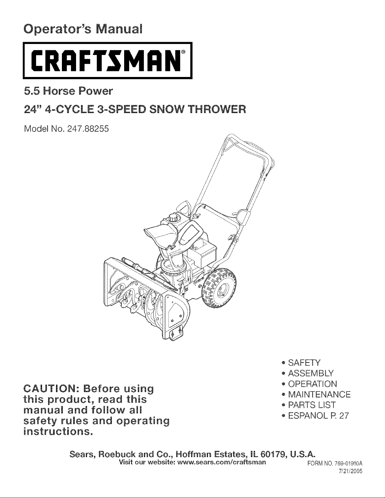
5.5 Horse Power
24" 4-CYCLE 3-SPEED SNOW THROWER
Model No. 247.88255
CAUTION: Before using
this product, read this
manual and follow aim
safety fumes and operating
o SAFETY
ASSEMBLY
OPERATION
MAINTENANCE
PARTS LIST
ESPANOL R 27
Sears, Roebuck and Co., Hoffman Estates, IL 60179, U.S.A.
Visit our website: www, sears,com/craftsman FORMNO,769=01910A
7/21/2005
Two-YearWarrantyonCraftsmanSnowThrower
Fortwoyearsfromthedateofpurchase,whenthisCraftsmanSnowThrowerismaintained,lubricatedandtunedupaccordingtotheinstructions
intheowner'smanual,Searswillrepair,freeofcharge,anydefectinmaterialandworkmanship,IfthisCraftsmansnowthrowerisusedfor
commercialorrentalpurposes,thiswarrantyapplbsforonly30daysfromthedateofpurchase,
Thiswarrantydoesnotcover:
, Expendabbitemswhichbecomewornduringnormaluse,suchasskidshoes,shaveplateandsparkplugs,
• Repairsnecessarybecauseofoperatorabuseornegligence,includingbentcrankshaftsandthefailuretomaintaintheequipmentaccording
totheinstructionscontainedintheowner'smanual
WARRANTYSERVICEISAVAILABLEBYRETURNINGTHECRAFTSMANSNOWTHROWERTOTHENEAREST
SEARSPARTS&REPAIRCENTERINTHEUNITEDSTATES,
ThiswarrantyapplbsonlywhilethisproductisinuseintheUnitedStates,
TOLOCATETHENEARESTSEARSPARTS&REPAIRCENTERORTOSCHEDULESERVICE,
SIMPLY"CONTACTSEARSAT1-800-4-MY-HOME®,
Thiswarrantygivesyouspecificlegalrightsandyoumayalsohaveotherrightswhichmayvaryfromstatetostate,
SEARS,ROEBUCKANDCO.,D/817WA,HOFFMANESTATES,IL60179
Repair Protection Agreements
Congratulationson makinga smart purchase,YournewCraftsman®
productis designedand manufacturedfor yearsof dependabbopera-
tion,But likeall products,it mayrequirerepairfrom time to time,That's
whenhavinga RepairProtectionAgreementcansaveyoumoneyand
aggravation,
Here'swhat'sincludedin the Agreement:
, Expertserviceby our 12,000professionalrepairspecialists
, Unlimitedserviceand nochargefor partsand laboron all covered
repairs
, Productreplacementif yourcoveredproductcan'tbe fixed
, Discountof 10%fromregularpriceof serviceandservice-related
partsnotcoveredby theagreement;also,10%off regularpriceof
preventivemaintenancecheck
• Fasthelp by phone- phonesupportfroma Searstechnicianon
productsrequiringin-homerepair,plus convenientrepair
scheduling
PurchaseaRepairProtectionAgreementnowand protectyourself
fromunexpectedhassleand expense,
Once youpurchasethe Agreement,a simplephonecall is all thatit
takesfor youto scheduleservice,Youcan call anytimeday ornight,or
schedub a serviceappointmentonline,
Searshasover12,000professionalrepairspecialists,who have
accessto over4,5millionquality partsand accessories,That'sthe
kindd
professionalismyou cancountonto helpprolongthe life of yournew
purchaseforyears to come,PurchaseyourRepairProtectionAgree-
menttoday!
Some limitations and exclusions apply. For prices and additional
information call 1-800o827o6655.
Sears Installation Service
ForSearsprofessionalinstallationof homeappliances,garagedoor
openers,waterheaters,andother majorhomeitems,in the U,S,A,call
1-800-4-MY-HOME®
Horse Power: 5.5
Engine Oil: SAE 5W_30
Fuel: Unleaded Gasoline
Spark Plug:
Engine: Tecumaeh LH195SP
Model Number .............................................................
Serial Number ..............................................................
Date of Purchase ..........................................................
Record the model number, serial number
and date of purchase above
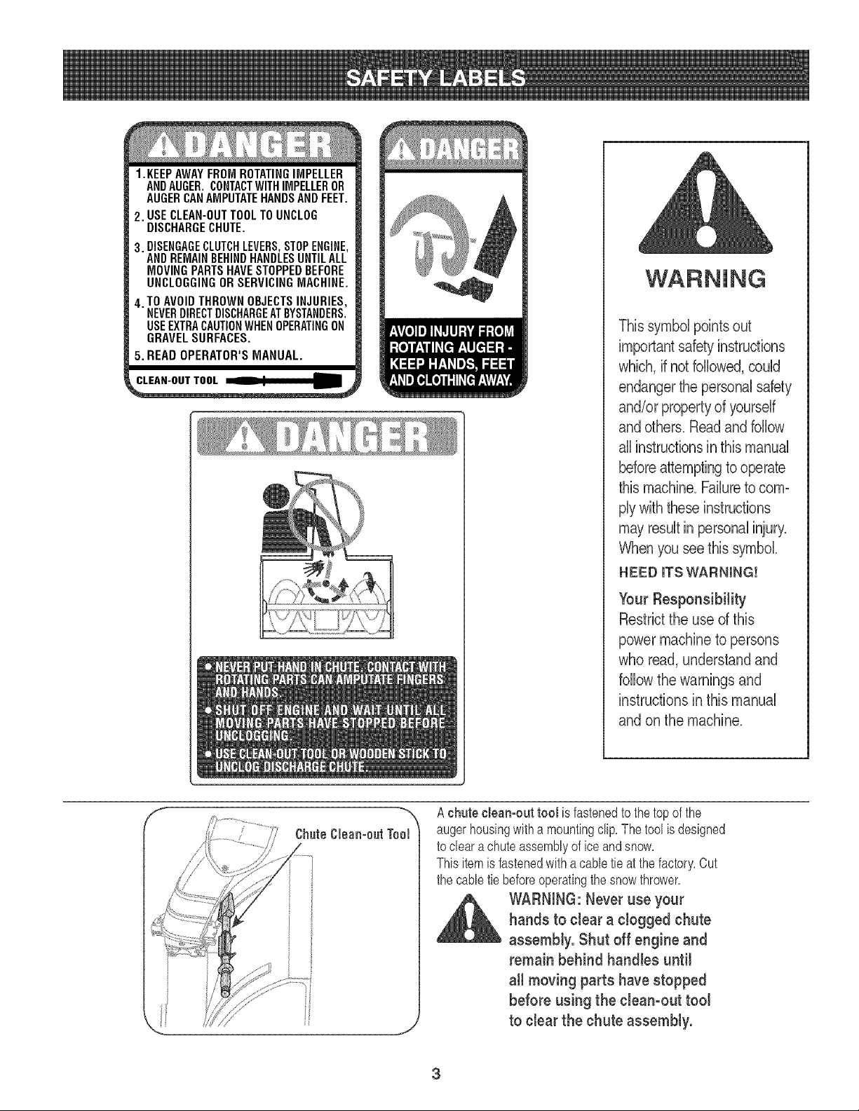
1.KEEPAWAYFROMROTATINGIMPELLER
ANDAUGER.CONTACTWITHIMPELLEROR
AUGERCANAMPUTATEHANDSANDFEET,
2. USECLEAN-OUTTOOLTOUNCLOG
DISCHARGECHUTE.
3. DISENGAGECLUTCHLEVERS,STOPENGINE,
ANDREMAINBEHINDHANDLESUNTILALL
MOVINGPARTSHAVESTOPPEDBEFORE
UNCLOGGINGOR SERVICINGMACHINE,
4. TO AVOIDTHROWNOBJECTSINJURIES,
NEVERDIRECTDISCHARGEATBYSTANDERS.
USEEXTRACAUTIONWHENOPERATINGON
GRAVELSURFACES.
5. READOPERATOR'SMANUAL.
This symbol points out
importantsafety instructions
which, if not followed,could
endangerthe personal safety
and/or propertyof yourself
and others. Readand follow
all instructionsin this manual
beforeattemptingto operate
this machine.Failureto com-
ply with these instructions
mayresult in personalinjury.
When you see this symbol.
HEED ITS WARNING!
Your Responsibility
Restrictthe use of this
power machineto persons
who read, understandand
follow the warnings and
instructions in this manual
and on the machine.
A chute cleamout tool is fastenedto the top of the
augerhousingwitha mountingclip,The tool is designed
to cleara chute assemblyof ice and snow,
Thisitemis fastenedwithacable tie at the factory,Cut
the cabletie beforeoperatingthe snowthrower,
,_ WARNING:Never use your
hands to clear a clogged chute
assembly. Shut off engine and
remain behind handles until
all moving parts have stopped
before using the clean-out tool
to clear the chute assembly.
3
WARNING:EngineExhaust,someofitsconstituents,andcertainvehiclecomponentscontainoremit
chemicalsknowntoStateofCaliforniatocausecancerandbirthdefectsorotherreproductiveharm.
DANGER:ThismachinewasbuilttobeoperatedaccordingtotherulesforsafeoperationinthismanualAswithanytype
ofpowerequipment,carelessnessorerroronthepartoftheoperatorcanresultinseriousinjury.Thismachineis capable
ofamputatinghandsandfeetandthrowingobjects.Failuretoobservethefollowingsafetyinstructionscouldresultin
seriousinjuryordeath.
WARNING:Thissymbolpointsoutimportantsafetyinstructionswhich,if notfollowed,couldendangerthe
personalsafetyand/orpropertyofyourselfandothers.Readandfollowallinstructionsinthismanualbefore
attemptingtooperatethismachine.Failuretocomplywiththeseinstructionsmayresultin personalinjury.
WhenyouseethissymbolHEEDITSWARNING!
YourResponsibility:Restricttheuseofthispowermachinetopersonswhoread,understandandfollowthewarnings
andinstructionsin thismanualandonthemachine.
Preparation
1. Thoroughlyinspectthe areawherethe equipmentisto be used. Remove
all doormats,newspapers,sleds, boards,wiresand otherforeignobjects,
whichcould be trippedoveror thrownbythe auger/impeller.
2. Alwayswearsafetyglassesor eye shields duringoperationandwhile
performingan adjustmentor repairto protectyoureyes.Thrownobjects
which ricochetcan causeserious injuryto the eyes.
3. Donot operatewithoutwearingadequatewinteroutergarments.Donot
wearjewelry,long scarvesor otherlooseclothing,whichcouldbecome
entangledin moving parts.Wear footwearwhichwill improvefootingon
slippery surfaces.
4. Usea groundedthree-wireextensioncord and receptaclefor all unitswith
electricstart engines.
5. Adjustcollector housingheightto clear gravelor crushedrock surfaces.
6. Disengageall controlleversbeforestartingthe engine.
7. Neverattemptto make anyadjustmentswhileengine is running,except
where specificallyrecommendedinthe operator'smanual.
8. Letengineand machineadjustto outdoortemperaturebefore startingto
clear snow.
9. To avoidpersonalinjury or propertydamageuse extremecare in handling
gasoline. Gasolineis extremelyflammableandthe vaporsareexplosive.
Seriouspersonalinjury can occurwhen gasolineis spilled on yourself
or yourclothes,which can ignite.Washyourskin andchangeclothes
immediately.
a. Useonlyan approvedgasolinecontainer.
b. Extinguishall cigarettes,cigars,pipes and othersourcesof ignition.
c. Neverfuelmachine indoors.
d. Neverremovegas capor addfuel whilethe engineis hot or running.
e. Allowengine to cool at least two minutesbefore refueling.
f. Neveroverfill fuel tank. Filltank to no morethan _J2inch belowbottom
of filler neckto providespacefor fuel expansion.
g. Replacegasolinecap andtighten securely.
h. If gasolineis spilled, wipeit offthe engineandequipment.Move
machineto anotherarea. Wait5 minutesbeforestartingthe engine.
Neverstore themachineor fuel container insidewherethere is an open
flame, sparkor pilot light (e.g.furnace,water heater,space heater,
clothesdryeretc.).
Allowmachineto cool at least5 minutesbeforestoring.
Training
1 Read,understand,andfollowall instructionson the machineand inthe
manual(s)beforeattemptingto assembleandoperate.Keepthis manualin
a safeplaceforfuture andregularreferenceandfor orderingreplacement
parts.
2. Be familiarwith all controlsandtheir properoperation.Knowhowto stop
themachineand disengagethem quickly.
3. Neverallowchildrenunder14 yearsoldto operatethis machine.Ohildren
14 yearsold andovershouldread andunderstandthe operationinstruc-
tionsand safetyrulesinthis manualandshouldbe trainedandsupervised
bya parent.
4. Neverallowadultsto operatethis machinewithoutproperinstruction.
5. Thrownobjectscan causeserious personalinjury'.Planyoursnow-throwing
patternto avoiddischargeof materialtowardroads,bystandersandthe like.
6. Keepbystanders,helpers,pets andchildrenat least 75 feetfrom the
machinewhileit is in operation.Stopmachineif anyoneentersthe area.
7. Exercisecautionto avoidslippingor falling,especiallywhenoperatingin
reverse.
4
Operation
1. Do not puthands orfeet nearrotatingparts, inthe auger/impellerhousing
orchute assembly.Contactwith the rotating partscan amputatehands
andfeet.
2. The auger/impellercontrolleveris a safetydevice.Neverbypassits
operation.Doingso makesthemachine unsafeand maycause personal
injury.
3. The control leversmust operateeasilyin both directionsand automatically
returnto the disengagedpositionwhenreleased.
4. Neveroperatewitha missingor damagedchute assembly.Keepall safety
devicesin placeand working.
5. Neverrunan engineindoorsor in a poorlyventilatedarea. Engineexhaust
containscarbonmonoxide,an odorlessanddeadlygas.
6. Do not operatemachinewhile underthe influenceof alcoholor drugs.
7. Mufflerand enginebecomehotand can causea burn. Donot touch.
8. Exerciseextremecautionwhen operatingon orcrossinggravel surfaces.
Stay alert forhiddenhazardsor traffic,
9. Exercisecautionwhenchangingdirectionandwhile operatingon slopes.
10.Plan yoursnow-throwingpatternto avoiddischargetowardswindows,
walls, carsetc.Thus, avoidingpossiblepropertydamageor personal
injurycausedby a ricochet.
11.Neverdirectdischargeat children,bystandersand petsor allowanyonein
front of the machine.
12.Do notoverloadmachinecapacityby attemptingto clearsnow at toofast
of a rate.
13.Neveroperatethis machinewithoutgood visibilityor light. Alwaysbe sure
of yourfootingand keepa firm holdon the handles.Walk, never run.
14.Disengagepowerto the auger/impellerwhen transportingor notin use.
15.Neveroperatemachineat hightransport speedson slipperysurfaces.
Lookdownand behindand use carewhen backingup.
16.If the machineshouldstart to vibrateabnormally,stop the engine,
disconnectthespark plugwire andground it againsttheengine.Inspect
thoroughlyfor damage.Repairany damagebeforestartingand operating.
17.Disengageall control leversandstop enginebeforeyou leavethe operat-
ing position(behindthe handles).Wait until theauger/impellercomes
to a completestop beforeuncloggingthechute assembly,makingany
adjustments,or inspections.
18.Neverput your hand inthe dischargeor collectoropenings.Alwaysuse
theclean-outtool providedto unclogthedischargeopening.Do notunclog
chuteassemblywhileengine is running.Shutoff engineand remain
behind handlesuntil allmoving partshavestoppedbeforeunclogging.
19.Use only attachmentsand accessoriesapprovedbythe manufacturer(e.g.
wheelweights,tire chains,cabs etc.).
20.If situationsoccurwhich are not coveredin this manual,use careand
goodjudgment. ContactyourSears ServiceCenterfor assistance.
Maintenance & Storage
1. Nevertamperwith safetydevices.Check their properoperationregularly.
Referto the maintenanceand adjustmentsectionsof this manual.
2. Beforecleaning, repairing,or inspectingmachinedisengageall control
leversand stop theengine.Wait until theauger/impellercometo a
completestop.Disconnectthe spark plugwire and groundagainstthe
engine to preventunintendedstarting.
3. Check bolts andscrewsfor propertightnessat frequentintervalsto keep
the machinein safeworkingcondition.Also, visuallyinspectmachinefor
any damage.
4. Donot changethe engine governorsettingor over-speedthe engine.The
governorcontrolsthe maximumsafeoperatingspeedof the engine.
5. Snowthrowershaveplatesandskid shoesaresubjectto wear and
damage.Foryour safetyprotection,frequentlycheck allcomponentsand
replacewithoriginal equipmentmanufacturer's(OEM)parts only."Useof
parts which donot meet the originalequipmentspecificationsmay leadto
improperperformanceand compromisesafety!"
6. Checkcontrols periodicallyto verifythey engageanddisengageproperly
and adjust,if necessary.Referto the adjustmentsectionin this operator's
manualfor instructions.
7. Maintainor replacesafetyand instructionlabels, as necessary.
8. Observeproperdisposallawsand regulationsfor gas, oil,etc. to protect
the environment.
9. Priorto storing,run machinea few minutesto clear snowfrom machine
and preventfreeze up of auger/impeller.
10.Neverstorethe machineor fuel containerinside wherethere is an open
flame, sparkor pilot light suchas a water heater,furnace,clothes dryer
etc.
11.Alwaysreferto the operator'smanualfor properinstructionson off-season
storage.
Do not modify engine
Toavoidseriousinjury'or death,do notmodifyenginein anyway.Tampering
withthe governorsettingcan leadto a runaway'engine andcauseit to operate
at unsafespeeds.Nevertamperwithfactorysettingof engine governor.
Notice regarding Emissions
Engineswhichare certifiedto complywith CaliforniaandfederalEPAemission
regulationsfor SORE(SmallOff RoadEquipment)are certifiedto operateon
regularunleadedgasoline,and may'includethefollowingemissioncontrol sys-
tems:EngineModification(EM)andThreeWayCatalyst(TWC)if so equipped.
Engine identification Decal
Thisdecal indicatestheengine'smodelnumber,specificationandthe dateof
manufacture.Pleaselook atthe decalon the engine ofyour equipmentand
recordthese informationforfuturereference.
The engineidentificationdecal also includesenginelifespecificationsfor the
emissions-relatedusefullifeperiodof the engine.This periodrelatesto the
emissioncompliancelife as certifiedby EPAand/orCARB.Tofind the lifeperiod
specificationof the engine,pleasereadthe enginedecaland locatethe letter
(enclosedbyquotationmarks)betweenthewordsModerateand LifePeriod.
Matchone of the followingletterswith theletter printedon yourdecal.For
example,HMSK80 modelsare designatedas:
"C"-- 250hours
"B"-- 500 hours
"A"-- 1000hours
IMPORTANT:This unitis shippedwith the enginefull of oil After
assembly,see page 10for fuel and oil details,
Removing From Carton
1, Cut the cornersof the cartonand lay the sidesflat on the ground,
Removeall packinginserts,
2, The upperhandleis packagedunattachedto the snowthrower,
thoughconnectedby canes, Movethe snowthrowerandupper
handleout of the carton,
3, Makecertainthe carton has beencompletelyemptiedbefore
discardingit,
Before Assembly
_lb ARNING:Disconnect the spark plug wire and Ground
itagainst the engine to prevent unintendedstarting.
NOTE: Referenceto right, left,frontor rearof the unitis from the
operatingpositionunlessotherwisestated,
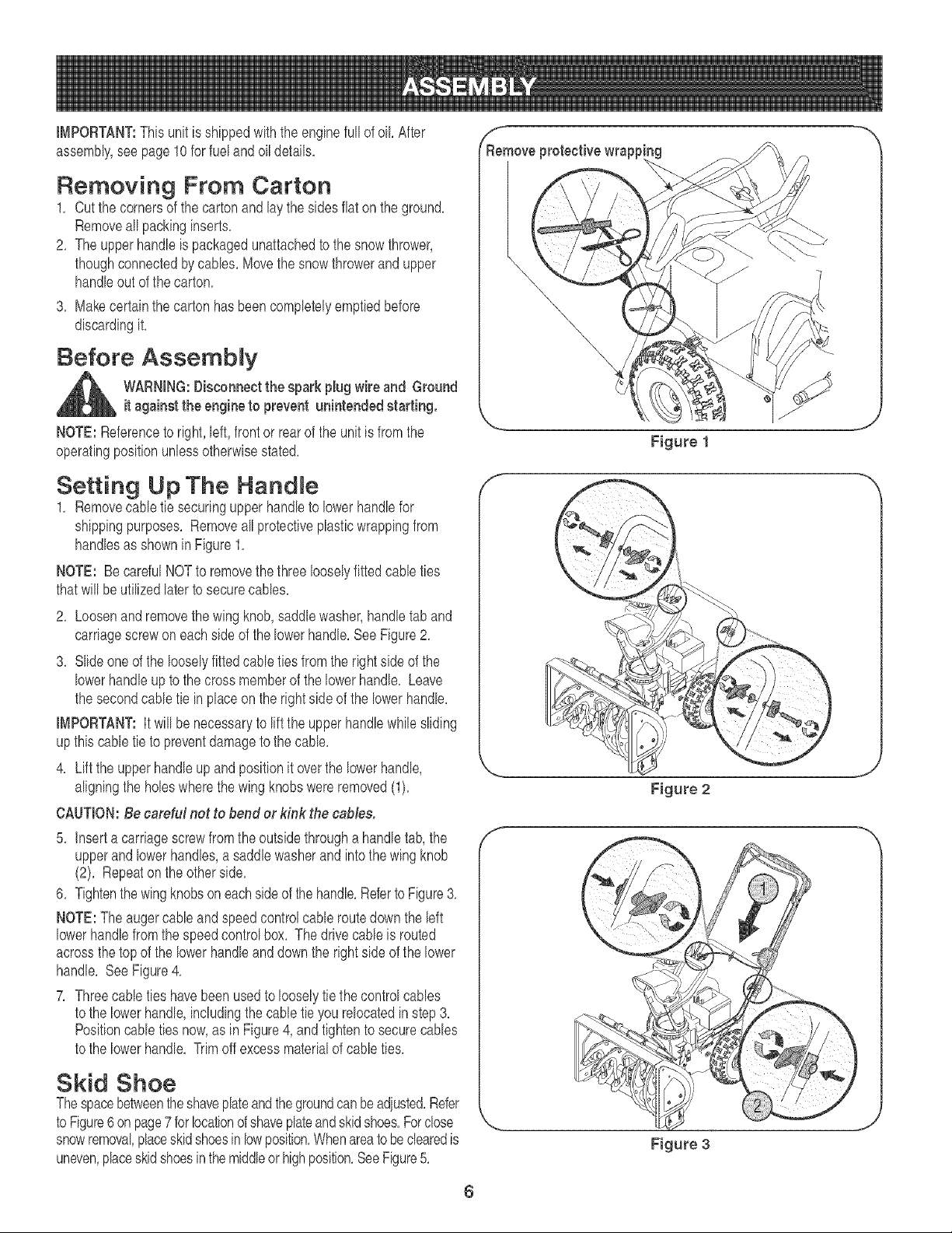
Setting Up The HandJe
1, Removecane tie securingupperhandleto lowerhandlefor
shippingpurposes, Removeall protectiveplasticwrappingfrom
handlesas shownin Figure1,
NOTE: BecarefulNOTto removethe threelooselyfittedcane ties
thatwill beutilizedlaterto securecanes,
2, Loosenand removethe wingknob,saddlewasher,handletab and
carriagescrewoneachside of the lowerhandle,SeeFigure2,
3, Slide one of the looselyfittedcane tiesfromthe rightside of the
lowerhandleup to the cross memberof the lowerhandle, Leave
the secondcane tie in placeon the rightside of the lowerhandle,
iMPORTANT:It will benecessaryto liftthe upperhandlewhilesliding
upthis cane tie to preventdamagetothe cane,
4, Lift the upperhandleup and positionit overthe lowerhandle,
aligningthe holeswherethe wing knobswereremoved(1),
CAUTION:Be careful net to bend er kink the came&
5, insert a carriagescrewfromthe outsidethrougha handletab, the
upperand lowerhandles,a saddlewasherand intothewing knob
(2), Repeaton the otherside,
6, Tightenthewingknobson eachsideof thehandle,Referto Figure3,
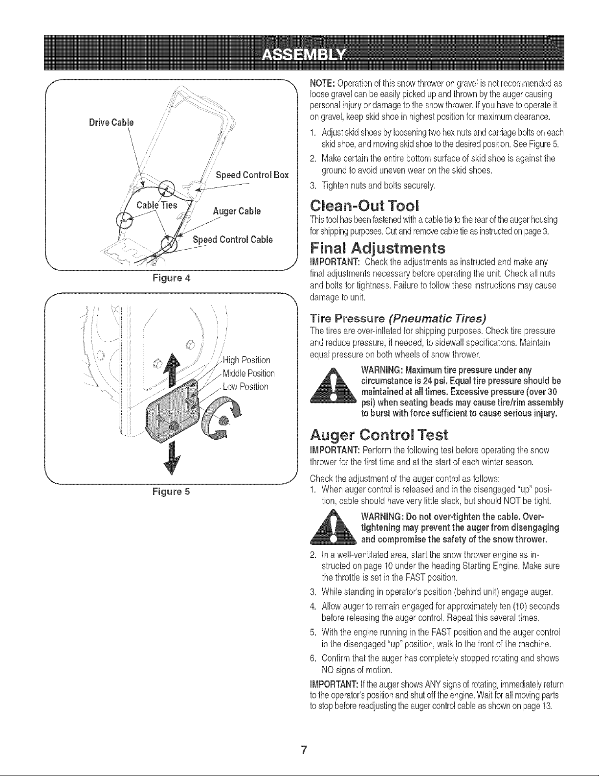
NOTE:The augercane and speedcontrolcane routedown the left
lowerhandlefromthe speedcontrolbox, The drivecane is routed
acrossthetop of the lowerhandleand downthe rightside of the lower
handle, SeeFigure4,
7, Threecane tieshavebeen usedto looselytie the controlcanes
to the lowerhandle,includingthe cane tie you relocatedinstep3,
Positioncane tiesnow,as in Figure4,and tightento securecanes
to the lowerhandle, Trimoff excessmaterialof cane ties,
Skid Shoe
Thespacebetweentheshaveplateand thegroundcanbe adiusted,Refer
to Figure6 on page7 forlocationofshaveplateandskidshoes,Fordose
snowremoval,placeskidshoesin lowposition,Whenareatobeclearedis
uneven,placeskid shoesin themiddleor highposition,SeeFigure5,
\
\
Figure 2
f
Figure 3
6
f -m
Drive Cable
Speed Control Box
f
Figure 4
Position
. MiddlePosition
. LowPosition
,... j
Figure 5
NOTE:Operationof thissnowthrowerongravelisnot recommendedas
loosegravelcanbeeasilypickedupandthrownbytheaugercausing
personaliniuryor damageto thesnowthrower.If you havetooperateit
on gravel,keepskidshoe in highestpositionfor maximumclearance.
1. Adiustskidshoesby looseningtwo hexnutsandcarriageboltson each
skidshoe,andmovingskidshoetothedesiredposition.SeeFigure5.
2. Makecertainthe entirebottomsurfaceof skidshoe is againstthe
groundto avoidunevenwearon theskid shoes.
3. Tightennuts and bolts securely.
C ean-Out TooR
Thistoolhasbeenfastenedwitha cabletietotherearoftheaugerhousing
forshippingpurposes.Cutandremovecabletieasinstructedonpage3.
FinaH Adjustments
IMPORTANT:Checkthe adiustmentsas instructedand makeany
final adjustmentsnecessarybeforeoperatingthe unit. CheckaIInuts
and boltsfor tightness.Failureto followthese instructionsmaycause
damageto unit.
Tire Pressure (Pneumatic Tires)
The tiresareover=inflatedfor shippingpurposes.Checktire pressure
and reducepressure,if needed,to sidewallspecifications.Maintain
equalpressureon bothwheelsof snow thrower.
WARNING:Ma×imumtire pressure underany
circumstanceis 24psi. Equaltire pressureshould be
maintainedat all times. Excessivepressure (over 30
psi) when seating beads maycausetire/rim assembly
to burst with force sufficient to causeserious injury.
Auger Contro Test
IMPORTANT:Performthe followingtestbeforeoperatingthe snow
throwerfor the firsttime and at the start of eachwinterseason.
Checkthe adiustmentof theaugercontrolas follows:
1. Whenaugercontrol is releasedand in thedisengaged"up"posi=
tion,cableshouldhavevery little slack, butshouldNOT be tight.
WARNING:Do not over-tighten the cable. Over-
tightening may preventthe auger from disengaging
and compromise the safety of the snow thrower.
2. ina well=ventilatedarea,startthe snowthrowerengineas in=
structedon page10underthe headingStartingEngine.Makesure
the throttleis set in the FASTposition.
3. Whilestandinginoperator'sposition(behindunit)engageauger.
4. Allowaugerto remainengagedfor approximatelyten (10)seconds
beforereleasingthe augercontrol Repeatthis severaltimes.
5. With the enginerunningin the FASTpositionand the augercontrol
inthe disengaged"up"position,walkto the frontof the machine.
6. Confirmthattheauger hascompletelystoppedrotatingandshows
NOsigns of motion.
IMPORTANT:If theaugershowsANYsignsof rotating,immediatelyreturn
to theoperator'spositionandshutofftheengine.Waitforall movingparts
to stopbeforereadjustingtheaugercontrolcableasshownonpage13.
7
Starter Rope
Gasoline Cap -.
Upper Chute
Drive
Control
Chute Assembly_
Clean-out Tool
Chute Handle
Chute Knob
,/
Shave Plate
Auger "_ SkidShoe
Figure 6
_ ARNING:Be familiar with all the controls on the snow thrower and their proper operation. Know bow to stop the machine
and disengage them quickly.
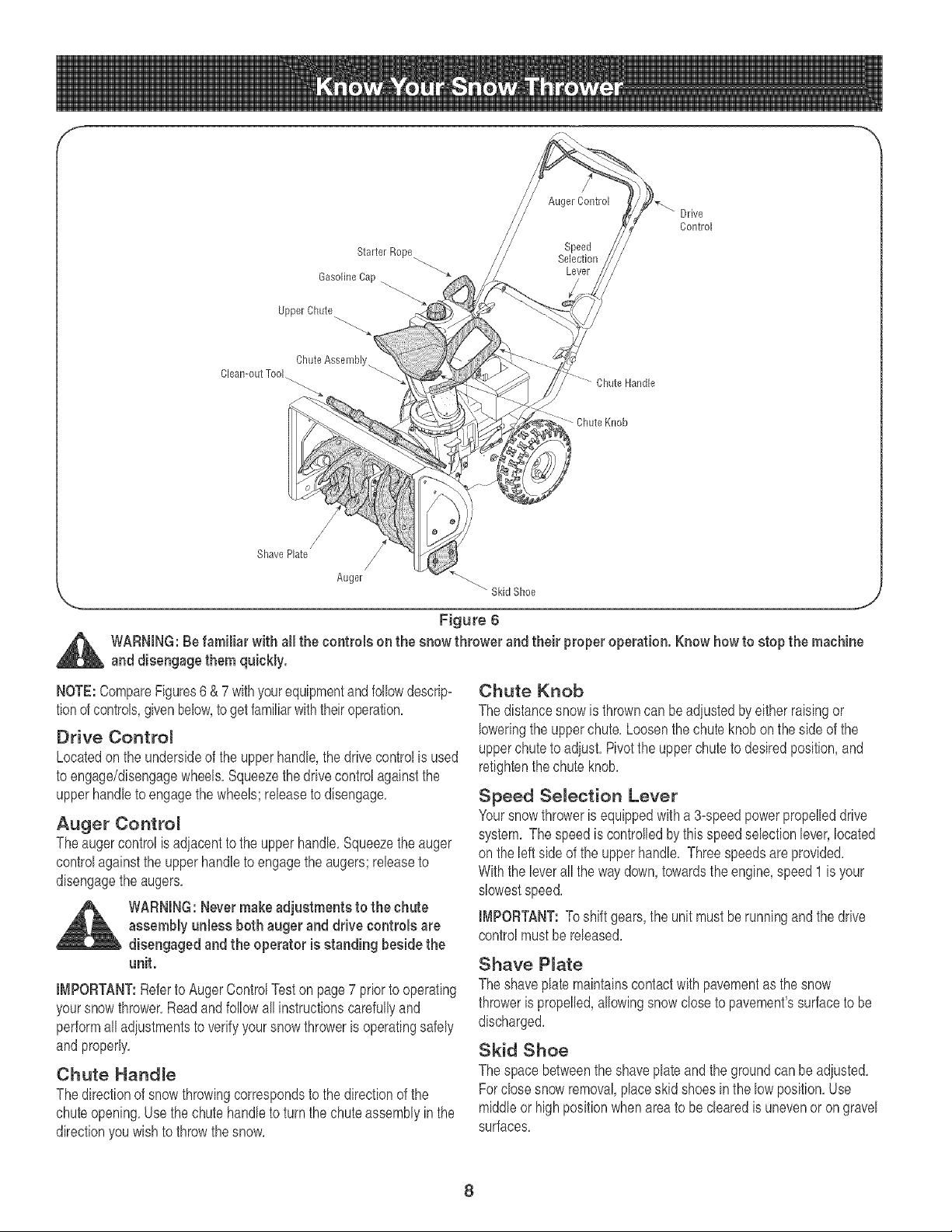
NOTE:CompareFigures6 & 7 withyourequipmentandfollowdescrip:
tionof controls,givenbelow,to getfamiliarwiththeiroperation.
Drive Controm
Locatedon the undersideof the upperhandle,the drivecontrolis used
to engage/disengagewheels.Squeezethe drivecontrolagainstthe
upperhandleto engagethe wheels;releaseto disengage.
Auger Contro_
Theauger controlis adiacentto the upperhandle.Squeezethe auger
controlagainstthe upperhandleto engagethe augers;releaseto
disengagethe augers.
WARNING:Nevermakeadjustments to the chute
assembly unless bothauger and drive controls are
disengaged and the operatoris standing beside the
unit.
IMPORTANT:Referto AugerControlTeston page7 priorto operating
yoursnow thrower.Readand followall instructionscarefullyand
performalladiustmentsto verifyyoursnow throweris operatingsafely
andproperly.
Chute HandJe
Thedirectionof snow throwingcorrespondsto the directionof the
chuteopening.Usethe chute handleto turnthe chute assemblyin the
directionyou wishto throwthe snow.
Chute Knob
The distancesnow is throwncan be adiustedbyeitherraisingor
loweringthe upperchute.Loosenthe chute knobonthe side of the
upperchuteto adiust.Pivotthe upper chuteto desiredposition,and
retightenthechute knob.
Speed Selection Lever
Yoursnowthroweris equippedwitha 3-speedpowerpropelleddrive
system. The speedis controlledby this speedselectionlever,located
on the leftside of the upperhandle. Threespeedsare provided.
Withthe leverall the way down,towardsthe engine,speed 1is your
slowestspeed.
iMPORTANT:Toshift gears,the unit mustbe runningand thedrive
controlmustbe released.
Shave P_ate
The shaveplatemaintainscontactwith pavementas the snow
throweris propelled,allowingsnow closeto pavement'ssurfaceto be
discharged.
Skid Shoe
The spacebetweentheshaveplate and the groundcan be adiusted.
Forclosesnow removal,placeskidshoesin the lowposition.Use
middleor high positionwhenareato beclearedis unevenor on gravel
surfaces.
8
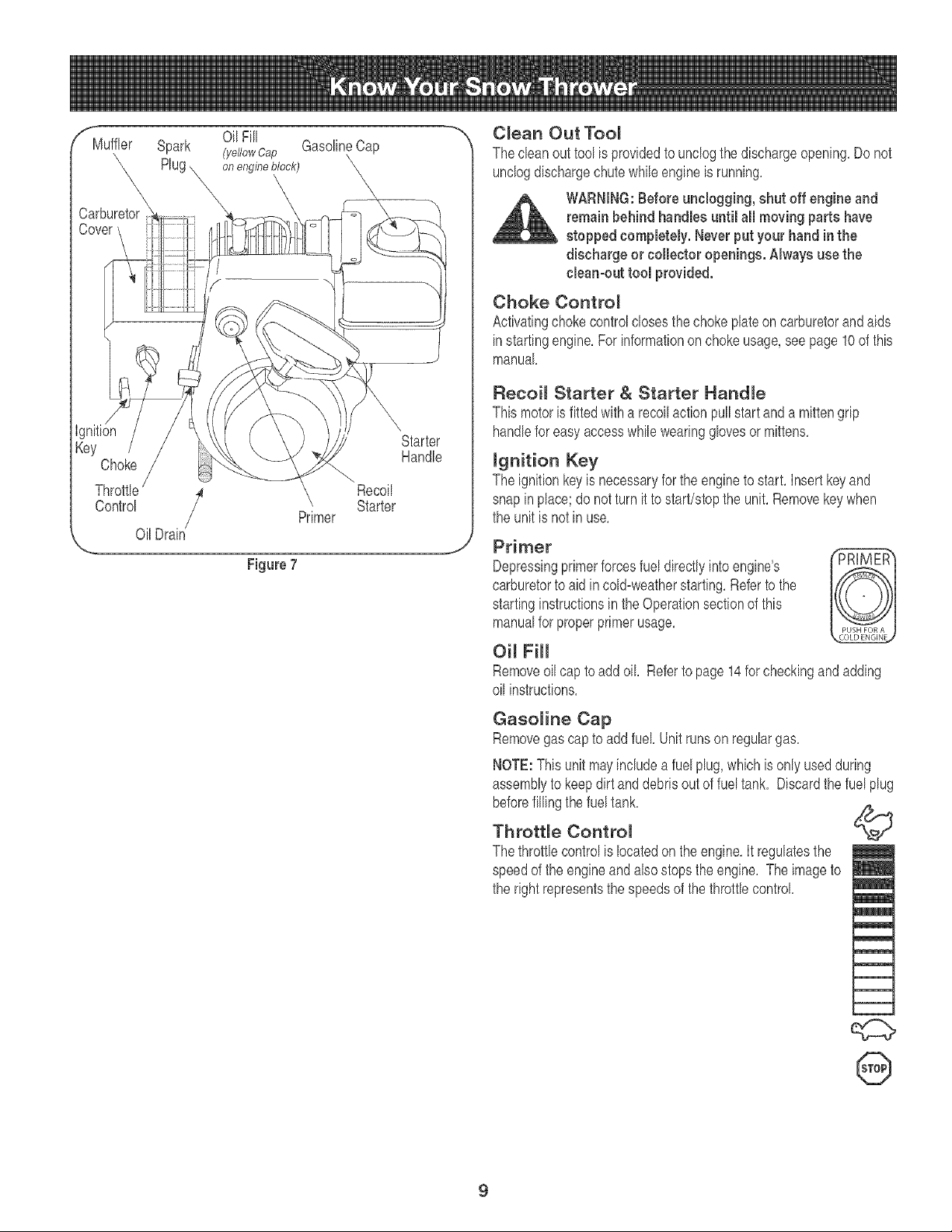
r_luffler
Carburetor
Cow
OilFill
Spark (ye//owcap GasolineCap
Rug onengineblock)
,\
\
Ignition
Key
Choke
Throttb /
Control
OilDrain
Figure 7
Recoil
Primer Starter
Starter
Handle
J
C_ean Out Too_
The cban out tool is providedto unclogthe dischargeopening,Do not
unclogdischargechute whileengineis running,
WARNING:Before unclogging, shut off engine and
remain behind handles until all moving partshave
stopped eompbtely. Never put your hand in the
discharge or collector openings. Always use the
chart-out tool provided.
Choke Contro_
Activatingchokecontrolclosesthe choke plateoncarburetorandaids
instartingengine,For informationonchokeusage,see page10 of this
manual
Recoi_ Starter & Starter Handme
Thismotoris fittedwith a recoilactionpullstartand a mittengrip
handlefor easyaccesswhilewearingglovesor mittens,
mgnition Key
The ignitionkeyis necessaryfor the engineto start, Insertkey and
snap inplace;do notturn it to start/stopthe unit, Removekeywhen
the unit is not in use,
Primer
Depressingprimerforcesfuel directlyinto engine's
carburetorto aid incold=weatherstarting,Referto the
startinginstructionsin the Operationsectionof this
manualfor properprimerusage,
Oi_ Fill
Removeoil capto addoil, Referto page 14for checkingand adding
oil instructions,
Gasoline Cap
Removegas capto add fuel,Unitrunson regulargas,
NOTE:This unit mayincludeafuel plug,which is only usedduring
assemblyto keepdirt and debrisoutof fueltank, Discardthe fuel plug
©
beforefillingthe fueltank,
Throttle Control
The throttb controlis locatedonthe engine,It regulatesthe
speedof the engineand abe stopsthe engine, The imageto
the right representsthe speedsof the throttb control,
@
9
Before Starting Engine
Engine OH
Theengine is shippedwith oil in it. Checkthe oil levelbeforefirst use.
Forsubsequentfill-ups,usethe gradeof engineoil specifiedon page
14.To add oil:
1. Removethe dipstickfromthe oilfill. Pourfreshoilslowlythrough
the plug.Replacedipstick.
2. Checkandmakesurethat the levelof oil is upto the FULLmarkon
the dipstick.
Gasoline
WARNING:Gasoline is flammable and caution must
be used when handling or storing it. Do not fill fuel
tank while the snow thrower is running,when it is
hot or when it is in an enclosed area.
WARNING:Keepyour snow thrower awayfrom any
open flame or an electrical spark and do not smoke
during fueling.
1. Neverfill the fueltankcompletely.Fill the tank to no morethan 1/2
inch belowbottomof filler neckto providespacefor expansionof
fuel
NOTE:This unit may includea fuel plug,whichisonly usedduring
assemblyto keepdirt and debrisout of fuel tank. Discardthefuel plug
beforefillingthe fuel tank.
2. Alwaysuseclean,fresh,unleadedgrade automotivegasoline.Fill
the fueltank outdoorsand usea funnelor spoutto preventspilling.
Makesurethat the containerfrom which you pourthe gasolineis
cleanand freefromrustor otherforeignparticles.Makesureto
wipeoff anyspilledfuel beforestartingthe engine.
3. At the end of theiob, emptythe fueltank if the snowthroweris not
goingto beusedfor 30 daysor longer.Storegasolinein a clean
containerand keepthe cap in placeon the container.
CAUTION:Never use engine or carburetor cleaner products in
the fuel tank.
To Start Engine
WARNING:Besure no oneother than the operator
is standing nearthe snow thrower while starting or
operating. Do not operate this snow thrower unless
the chute assembly has been properly installed and
is secured.
NOTE: Forlocationof all the enginecontrolsreferredto in this section,
referto Figure7.
For A Co_d Start
1. Makesurethataugeranddrivecontrolsare released.Attachspark
plugwireto spark plug.
2. Turnfuel valveon, if so equipped.
3. Movethrottlecontrolto FASTposition.
4. Pushkeyintotheignitionslotsothatitsnapsintoplace.Donotturnkey'.
5. Rotatechoke controlto FULLchoke position.
6. Pushprimerbuttonwhilecoveringthe venthole.Removeyour
fingerfrom the primerbetweenprimes.Donot primeif temperature
is above500F; primetwo timesbetween500F and 150F; and
primefour timesbelow150R
7. Graspstarterhandleand pull ropeout slowlyuntilengine reaches
start of compressioncycle (ropewill pullslightlyharderat this
point).Let the roperewindslowly.
8. Pull ropewith a rapid,continuous,full armstroke.Keepinga firm
gripon the starterhandle,let the rope returnto thestarterslowly.
Repeatuntilenginestarts.
9. As the enginewarmsup,rotate thechokeknobslowlyto OFF
position.If theenginefalters,returnto FULLchoke,thenslowly
moveto OFFchokeposition.
lO.Allowthe engineto warmupfor a fewminutesbecausethe engine
will not developfull poweruntilit reachesoperatingtemperature.
11.Operatethe engineat fullthrottle(FAST)whenthrowingsnow.
For A Warm Start:
1. if restartingan engineafter a temporaryshut- down,rotatechoke
to OFFinsteadof FULLanddo not prime.Pullstarterhandleas
instructedbefore.
Before Stopping
1. Runenginefora fewminutesto helpdryoff anymoistureonengine.
2. Toavoidpossiblefreeze-upof the starter,followthesesteps:
Reeoi_ Starter
a. Withthe enginerunning,pull thestarterrope with a rapid,
continuousfullarm strokethreeorfour times.
To Stop The Snow Thrower
1. Tostop the wheels,releasethe drivecontrol
2. Tostopthrowingsnow,releasetheaugercontrol
3. Tostopengine,pushthrottlecontrolleverto OFFandpullout the
key'.Do notturn key.
C earing The Snow
CAUTION:Checkthe area to be clearedforforeignobiects.Remove
foreignobiects,if any.
1. Startthe enginefollowingstartinginstructions.
2. Allowthe engineto warmupfor a fewminutesas the enginewill
not developfull poweruntilit reachesoperatingtemperature.
3. Rotatethe chuteassemblyto the desireddirection,awayfrom
bystandersand/or buildings.
4. Makingcertain no bystandersor obstaclesare in front of the unit,
squeezetheauger controlcompletelyagainstthe upperhandleto
fullyengagethe augers.
5. Whilethe augercontrolis engaged,squeezethe drivecontrol
completelyagainstthe upperhandletoengagethe wheels.Do not
"feather"the drh,'econtrol
10
6. As thesnowthrowerstartsto move,maintaina firm holdon the
handle,and guide the snowthroweralongthe pathto becleared.
7. Releasethe auger and drivecontrolsto stop the snowthrowing
actionandforwardmotion.
NOTE:Yourunit is equippedwith a clutch in the transmission.If the
wheelsstopturningwhiletryingto dischargelargevolumesof snow,
immediatelydisengagethe drivecontrolandallowthe rotatingaugers
to dischargesnowfromthe housing.Reducetheclearingwidthand
continueoperation.
8. On eachsucceedingpass,readiustthe chuteassemblyto the
desiredpositionand slightlyoverlapthe previouslyclearedpath.
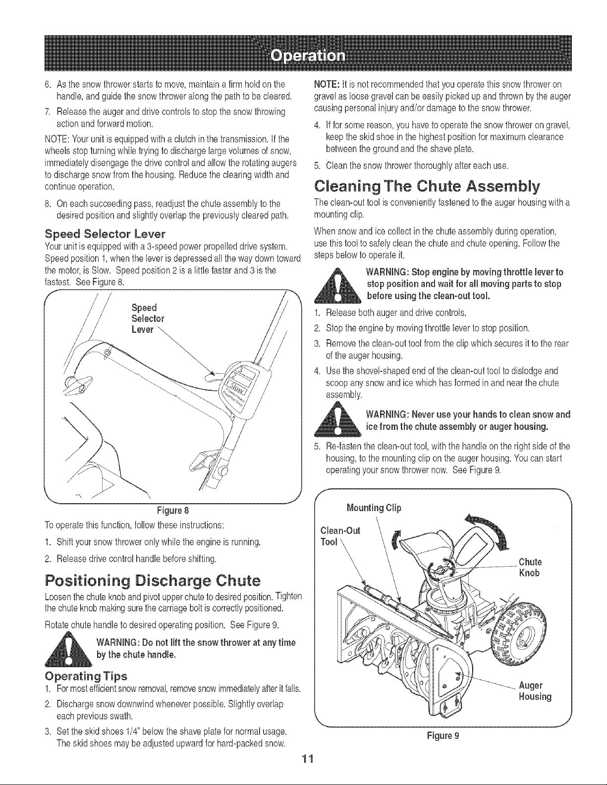
Speed Selector Lever
Yourunit is equippedwitha 3-speedpowerpropelleddrive system.
Speedposition1,whenthe leveris depressedall the way downtoward
the motor,is Slow. Speedposition2 is a littlefasterand 3 is the
fastest. SeeFigure8.
f
Speed
Selector
Lever _
\.,
Figure 8
To operatethis function,followthese instructions:
1. Shift yoursnowthroweronly whilethe engineis running.
2. Releasedrive controlhandlebeforeshifting.
Positioning Discharge Chute
Loosenthechuteknobandpk_otupperchuteto desiredposition.Tighten
thechuteknobmakingsurethecarriageboltis correctlypositioned.
Rotatechute handleto desiredoperatingposition. See Figure9.
_ll ARNING:Do not lift the snow thrower at any time
by the chute handle.
Operating Tips
1. Formostefficientsnowremoval,removesnowimmediatelyafterit falls.
2. Dischargesnowdownwindwheneverpossible.Slightlyoverlap
eachpreviousswath.
3. Set theskidshoes1/4" belowthe shaveplatefor normalusage.
Theskid shoes may be adjustedupwardfor hard-packedsnow.
11
NOTE:It is not recommendedthatyouoperatethissnowthroweron
gravelas loosegravelcan be easily pickedup and thrownbythe auger
causingpersonaliniuryand/or damageto the snowthrower.
4. if for somereason,you haveto operatethe snowthrowerongravel,
keepthe skid shoe in the highestpositionfor maximumclearance
betweenthe groundandthe shaveplate.
5. Cleanthe snowthrowerthoroughlyaftereachuse.
C eaning The Chute Assembly
The cleamouttoolis convenientlyfastenedto the auger housingwith a
mountingclip.
Whensnow and ice collectinthe chuteassemblyduringoperation,
usethis tool to safelyclean thechuteandchuteopening.Followthe
stepsbelowto operateit.
_L ARNING: Stop engine by moving throttle lever to
stop position and wait for all moving parts to stop
before using the clean-out tool.
1. Releasebothaugeranddrh,'econtrols.
2. Stoptheengineby movingthrottleleverto stopposition.
3. Removethe cleamouttool from the clipwhichsecuresit to the rear
of the augerhousing.
4. Usethe shovel_shapedend of the cleamouttoolto dislodgeand
scoopanysnow and ice whichhas formedin and nearthe chute
assembly.
WARNING:Neveruse your hands to clean snow and
icefrom the chute assembly or auger housing.
5. Re-fastenthe eleamouttool,withthe handleonthe rightside of the
housing,to the mountingclip onthe augerhousing.Youcan start
operatingyoursnowthrowernow. SeeFigure9.
f
Mounting Clip
Chute
Knob
Figure 9
Auger
Housing
GeneraR Recommendations
1, Alwaysobservesafetyruleswhen performingany maintenance,
2, Thewarrantyon this snowthrowerdoesnot coveritemsthat have
beensubiectedto operatorabuseor negligence,To receivefull
valuefromthe warranty,operatormust maintainthe snowthrower
as instructedin thismanual,
3, Periodicallycheckall fastenersand hardwareto makesure these
aretight,
WARNING: Before servicing, repairing, lubricating or
inspecting, disengage all controls and stop engine.
Wait until all moving parts have come to a complete
stop. Disconnectspark plug wire and ground itagainst
the engineto preventunintendedstarting.Alwayswear
safety glasses during operation or while performing
anyadjustmentsor repairs.
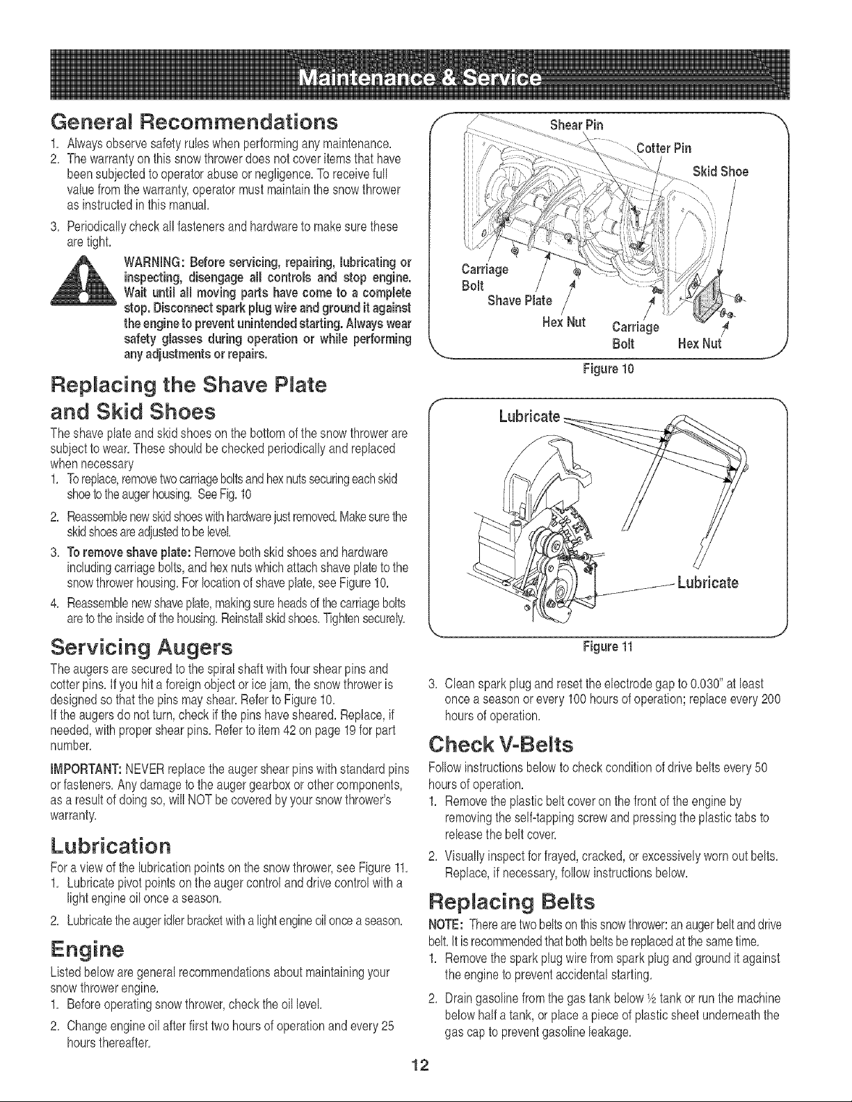
Replacing the Shave P ate
and Skid Shoes
Theshave plateand skid shoes on the bottomof the snowthrowerare
subiectto wear,These shouldbecheckedperiodicallyandreplaced
whennecessary
1, Toreplace,removetwo carriageboltsandhexnutssecuringeachskid
shoetotheaugerhousing,SeeFig,10
2, Reassemblenewskidshoeswithhardwareiustremoved,Makesurethe
skidshoesareadiustedtobe level
3, Toremoveshaveplate: Removebothskidshoesandhardware
includingcarriagebolts,and hexnutswhichattachshaveplateto the
snowthrowerhousing,Forlocationof shaveplate,see Figure10,
4, Reassemblenewshaveplate,makingsureheadsof thecarriagebolts
aretothe insideof thehousing,Reinstallskidshoes,Tightensecurely,
Servicing Augers
Theaugersaresecuredto the spiralshaftwithfourshearpins and
cotterpins, If you hit a foreignobject or iceiam,the snowthroweris
designedso that the pinsmayshear,Referto Figure10,
if the augersdo notturn,checkif the pinshavesheared,Replace,if
needed,with propershearpins,Referto item42on page19for part
number,
IMPORTANT:NEVERreplacetheauger shearpinswith standardpins
orfasteners,Anydamagetothe augergearboxorothercomponents,
as a resultof doingso,will NOTbe coveredby yoursnowthrower's
warranty,
Lubrication
Fora view of the lubricationpointson the snowthrower,see Figure11,
1, Lubricatepivot pointson the auger controland drivecontrolwitha
lightengine oil oncea season,
2, Lubricatetheaugeridlerbracketwitha lightengineoil oncea season,
Listedbeloware generalrecommendationsabout maintainingyour
snowthrowerengine,
1, Beforeoperatingsnow thrower,checkthe oil level
2, Changeengineoil afterfirst two hoursof operationandevery25
hoursthereafter,
f
Shear Pin
Cotter Pin
Skid Shoe
Carriage
Bolt / /
Shave Plate _
Hex Nut Carriage
Bolt HexNut
,.... j
Figure 10
Lubricate
Figure 11
3, Cleansparkplugand resetthe electrodegap to 0,030"at least
once a seasonor every100hoursof operation;replaceevery200
hoursof operation,
Check V-BeRts
Followinstructionsbelowto checkconditionof drivebeltsevery50
hoursof operation,
1, Removethe plasticbeltcoveron the frontof the engineby
removingthe self=tappingscrewand pressingtheplastictabs to
releasethe beltcover,
2, Visuallyinspectfor frayed,cracked,or excessivelywornout belts,
Replace,if necessary,followinstructionsbelow,
Replacing BeRts
NOTE:Therearetwo beltson thissnowthrower:anaugerbeltanddrive
belt,It isrecommendedthatbothbeltsbe replacedat thesametime,
1, Removethe sparkplugwirefrom spark plug and groundit against
the engineto preventaccidentalstarting,
2, Draingasolinefrom the gas tank below1/2tankor runthe machine
belowhalf a tank, or placeapieceof plasticsheetunderneaththe
gas cap to preventgasolineleakage,
12
f
f
f
Top Auger
.... ..... H?us!ngS e ,_j
/ i
Figure 12
Figure 13
\
Wood Block
J
Figure 14
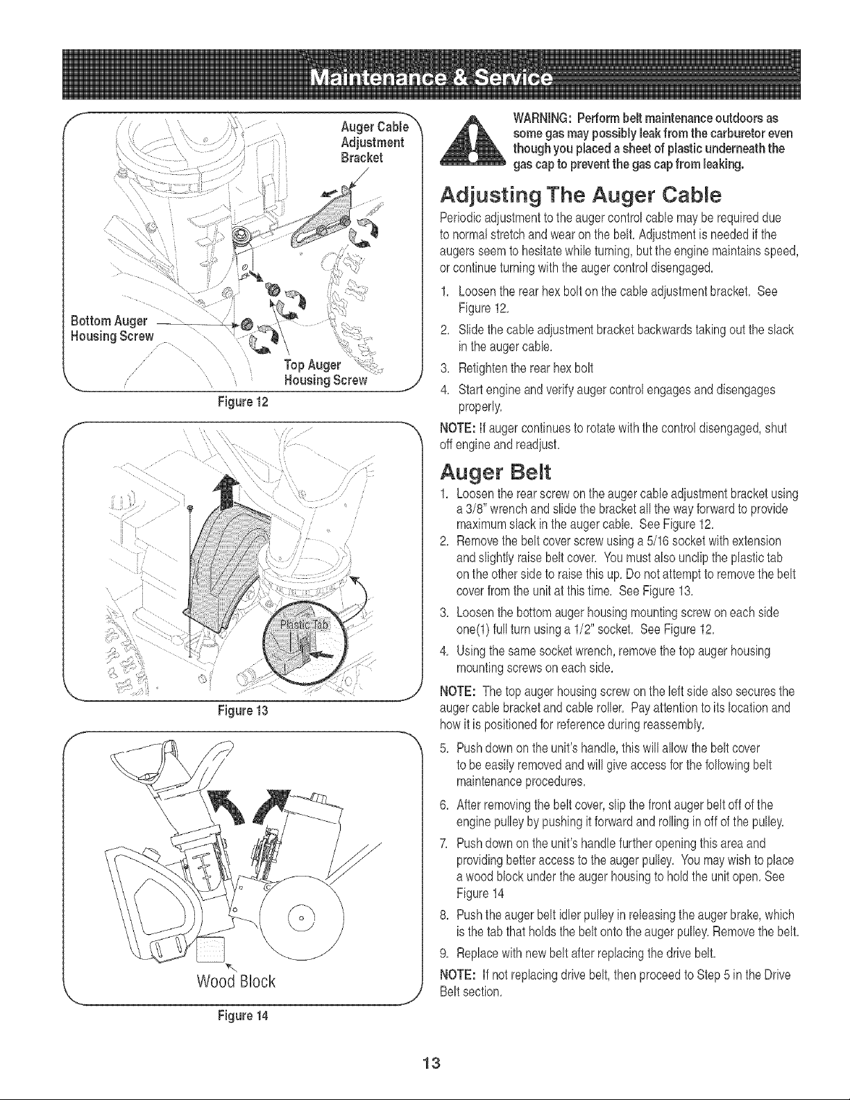
WARNING:Performbelt maintenanceoutdoors as
somegas maypossibly leakfrom the carburetor even
though you placeda sheet of plasticunderneaththe
gas cap to preventthe gascap from leaking.
Adjusting The Auger Cable
Periodicadiustmentto the augercontrol cablemayberequireddue
to normalstretchand wearonthe belt,Adiustmentis neededif the
augersseemto hesitatewhib turning,butthe enginemaintainsspeed,
or continueturningwith the augercontroldisengaged,
1, Loosenthe rear hex boltonthe cabb adiustmentbracket, See
Figure12,
2, Slidethecabb adiustmentbracketbackwardstakingout theslack
inthe augercabb,
3, Retightenthe rear hex bolt
4, Startengineandverifyaugercontrolengagesand disengages
properly,
NOTE:If augercontinuesto rotatewith the controldisengaged,shut
off engineandreadiust,
Auger Beret
1, Loosenthe rearscrewonthe augercableadjustmentbracketusing
a 3/8" wrenchandslidethe bracketall thewayforwardto provide
maximumslack inthe augercable, SeeFigure12,
2, Removethe belt coverscrewusinga 5/16 socketwith extension
andslightlyraisebelt cover, Youmustabe unclipthe plastictab
on theotherside to raisethis up, Donot attemptto removethe belt
coverfromthe unit at thistime, See Figure13,
3, Loosenthe bottomauger housingmountingscrewoneach side
one(l) fullturn usinga 1/2" socket, SeeFigure12,
4, Usingthe samesocketwrench,removethe topaugerhousing
mountingscrewson eachside,
NOTE: The topauger housingscrewonthe leftside abe securesthe
augercabb bracketand cabb roller, Payattentionto its locationand
howit is positionedfor referenceduring reassembly,
5, Pushdownon the unit'shandle,this willallowthe beltcover
to be easilyremovedand willgive accessfor the followingbelt
maintenanceprocedures,
6, After removingthe belt cover,slip thefrontaugerbeltoff of the
enginepulleyby pushingit forwardandrollingin offof the pulley,
7, Pushdownon the unit'shandlefurtheropeningthisareaand
providingbetteraccess to the augerpulley, Youmay wish to place
a woodblock underthe auger housingto holdthe unitopen,See
Figure14
8, Pushthe auger beltidlerpulleyin releasingthe augerbrake,which
isthe tab that holdsthe belt ontothe augerpulley,Removethe belt,
9, Replacewithnewbelt after replacingthe drivebelt,
NOTE: If not replacingdrivebelt,thenproceedto Step5 inthe Drive
Beltsection,
13
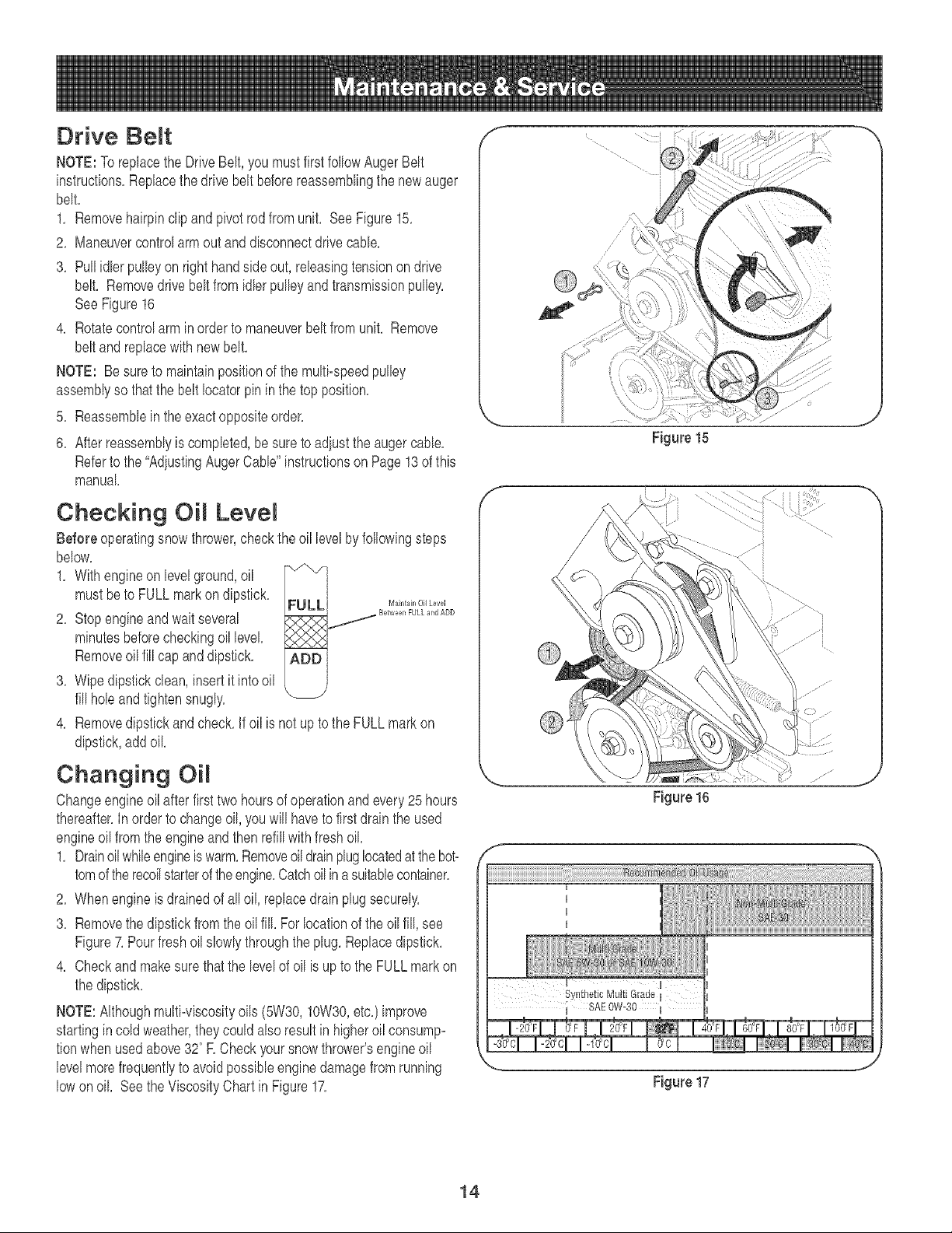
Drive Be t
NOTE:To replacethe DriveBelt, you mustfirstfollow AugerBelt
instructions,Replacethe drivebelt beforereassemblingthe newauger
belt,
1, Removehairpinclipand pivotrodfromunit, SeeFigure15,
2, Maneuvercontrolarmout anddisconnectdrivecable,
3, Pull idler pulleyon right handsideout, releasingtensionon drive
belt, Removedrivebelt from idlerpulleyandtransmissionpulley,
SeeFigure16
4, Rotatecontrolarm in orderto maneuverbelt from unit, Remove
beltand replacewith new belt,
NOTE: Besureto maintainpositionof the multi-speedpulley
assemblyso thatthe belt Iocatorpin in thetop position,
5, Reassemblein theexactoppositeorder,
6, After reassemblyis completed,be sureto adiustthe augercable,
Referto the "AdiustingAugerCable"instructionson Page13 of this
manual
Checking Lever
Before operatingsnow thrower,checkthe oil levelbyfollowingsteps
below,
1, With engineon levelground,oil '_/"'/
mustbe to FULLmarkon dipstick, FULL Maintair,OilLevel
2, Stopengineandwaitseveral
X P<'X _
minutesbeforecheckingoillevel......
Removeoil fill cap and dipstick, ADD
3, Wipedipstickclean,insertit intooil
fill holeandtightensnugly, '_
4, Removedipstickandcheck,If oil is not upto the FULLmarkon
dipstick,add oil
Changing OiR
Changeengineoil after firsttwo hoursof operationandevery25hours
thereafter,Inorder to changeoil,you will haveto firstdrain the used
engineoil fromthe engineandthen refillwith fresh oil,
1, Drainoilwhileengineis warm,Removeoil drainpluglocatedatthe bot-
tomof therecoilstarterof theengine,Catchoilina suitablecontainer,
2, Whenengineis drainedof alloil, replacedrain plugsecurely,
3, Removethe dipstickfromthe oilfill, For locationof theoil fill, see
Figure7,Pourfreshoilslowlythroughtheplug, Replacedipstick,
4, Checkandmakesurethat the levelof oil is upto the FULLmarkon
the dipstick,
NOTE:Althoughmulti-viscosityoils (5W30,10W30,etc,)improve
startingin cold weather,theycouldalso resultin higheroil consump-
tionwhen usedabove320R Checkyoursnowthrower'sengineoil
levelmorefrequentlyto avoidpossibleenginedamagefrom running
lowon oil Seethe ViscosityChart in Figure17,
f
f
/
//
Figure 15
Figure 17
14
2 3
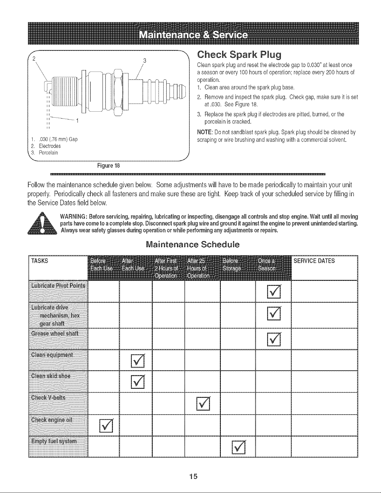
1, .030(.76 ram)Gap
2. Electrodes
L Porcelain
Check Spark PRug
Cleanspark plug and resetthe electrodegap to 0.030"at least once
a seasonor every100hoursof operation;replaceevery200 hoursof
operation.
1. Cleanarea aroundthesparkplugbase.
2. Removeand inspectthespark plug. Checkgap, makesureit is set
at .030. SeeFigure18.
3. Replacethe sparkplugif electrodesare pitted,burned,or the
porcelainis cracked.
NOTE:Donot sandblastspark plug. Sparkplug shouldbecleanedby
scrapingor wirebrushingand washingwith a commercialsolvent.
/
Figure 18
Followthe maintenance schedulegiven below, Some adjustmentswill have to be made periodicallyto maintainyour unit
properly, Periodicallycheck all fasteners and make sure these are tight, Keeptrack of your scheduled service by filling in
the Service Dates field below,
WARNING:Beforeservicing, repairing,lubricating or inspecting,disengageall controls andstop engine.Wait until all moving
partshavecome to a completestop. Disconnectspark plug wire and ground it againstthe engineto preventunintendedstarting.
Always wearsafety glassesduringoperation orwhile performingany adjustmentsor repairs.
Maintenance Schedule
TASKS SERVICEDATES
15
if the snowthrowerwill notbe usedfor 30daysor longer,or if it is the
endof the snowseasonwhenthe last possibilityof snowis gone,the
equipmentneedsto be stored properly,Followstorageinstructions
belowto ensuretop performancefromthesnow throwerfor many
moreyears,
Preparing Engine
NOTE: Referto the enginemanualfor moredetailedinformationon
preparingthe snowthrowerenginefor storage,
WARNING:Neverstore snow thrower with fuel in
tank indoors or in poorly ventilated areas,where
fuel fumes may reach an openflame, spark or pilot
light as on a furnace, water heater,clothes dryer or
gas appliance.
NOTE: It is importantto preventgumdepositsfromforming in
essentialfuelsystempartsof theenginesuchas the carburetor,fuel
filter,fuel hoseor tank duringstorage,
CAUTION:Alcohol blended fuels (called gasohd or using ethanol
or methanol) can attract moisture which leads to separation and
formation of acids during storage, Acidic gas can damage the
fuel system of an engine while in storage,
Toavoidengineproblems,thefuel systemshouldbe emptiedbefore
storagefor 80daysor longer,Followthese instructionsto prepareyour
snowthrowerfor storage:
WARNING:Drain fuel into an approved container
outdoors, awayfrom any open flame. Be certain
engine is cool. Do not smoke. Fuel left in engine
during warm weatherdeteriorates and will cause
serious starting problems.
1, Removeall gasolinefrom the carburetorand thefuel tankto
preventgum depositsfrom formingon these partsand harmingthe
engine,
2, Runthe engineuntil thefuel tank is emptyandit stops dueto lack
of fuel
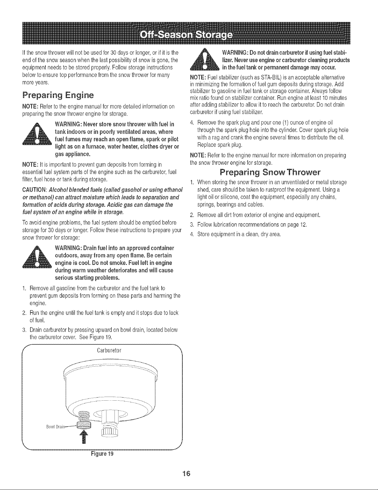
8, Draincarburetorby pressingupwardon bowldrain,locatedbelow
the carburetorcover, SeeFigure19,
S Carburetor -_
_L ARNING:Do not drain carburetor if usingfuel stabi-
lizer.Neveruse engineor carburetorcleaningproducts
inthe fuel tank or permanentdamagemay occur.
NOTE:Fuelstabilizer(suchas STA=BIL)is anacceptabb alternative
inminimizingthe formationof fuelgum depositsduringstorage,Add
stabilizerto gasolineinfuel tankorstoragecontainer,Alwaysfollow
mixratiofoundonstabilizercontainer,Runengine at bast 10 minutes
afteraddingstabilizerto allow it to reachthe carburetor,Do not drain
carburetorif usingfuelstabilizer,
4, Removethe spark plugand pourone (1) ounceof engineoil
throughthe sparkplug hob intothe cylinder,Coverspark plughob
witha ragandcrankthe engineseveraltimes to distributetheoil,
Replacesparkplug,
NOTE:Referto the enginemanualfor moreinformationon preparing
the snowthrowerenginefor storage,
Preparing Snow Thrower
1, Whenstoringthe snow throwerin an unventilatedor metalstorage
shed,careshouldbetakento rustprooftheequipment,Usinga
light oilor silicone,coat the equipment,especiallyanychains,
springs,bearingsand canes,
2, Removeall dirtfromexteriorof engineand equipment,
3, Follow lubrbationrecommendationson page 12,
4, Storeequipmentina clean,dry area,
Figure 19
16
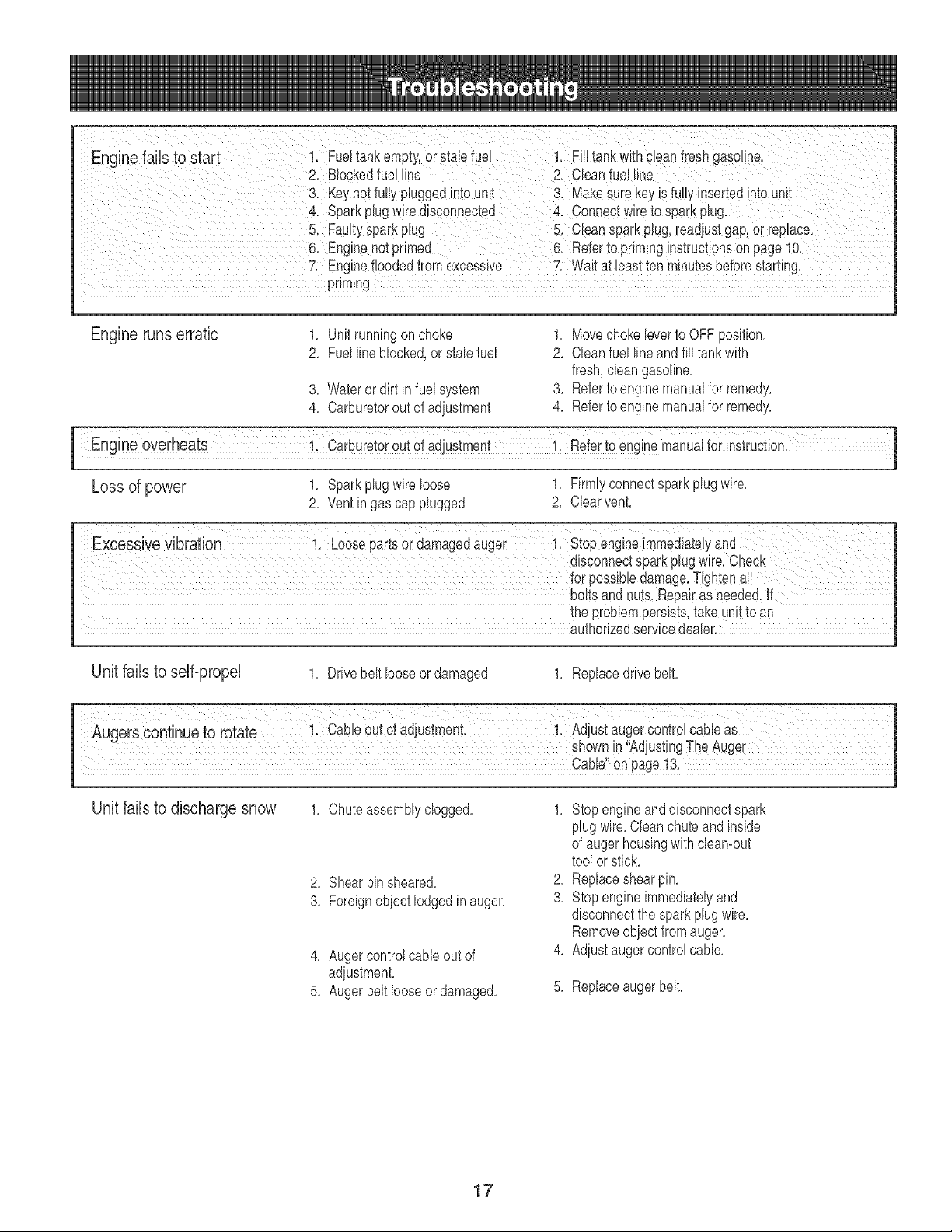
iiiiiiiill i i _ _ _i i i _ i ii_iii{ _ ii_i_ _ _i_ _i _ i_i xi_i i _x_ _i_ii_ ii_ _ _iii_i i_iii _ i_iilrill i ii_ii ii _
Enginefaib tOStart i: Fueltar]kemptY:or StaEefuel i. FiEItank With#ieanflesh gaSQ!!r]el
2. Blockedfuel line 2. Cleanfuel Line
3. Key net fullypBggedinto unit 3, Make Surekeyis fuElyinsertedinto unit
priming
Engine runs erratic 1. Unit runningon choke
2. Fuellineblocked,orstab fuel
3. Wateror dirt in fuel system
4. Carburetorout of adiustment
1. Movechoke leverto OFFposition.
2. Cleanfuel lineandfill tankwith
fresh,cban gasoline.
3. Referto enginemanualfor remedy.
4. Referto enginemanualfor remedy.
Loss of power 1. Spark plug wire loose 1. Firmly connect spark plug wire.
2. Vent in gas cap plugged 2. Char vent.
boltsand nuts,Repairas needed.If
the problempersists,take unitto an
authorizedservbe dealer.
Unit fails to self-propel
1. Drivebelt looseor damaged 1. Replacedrivebelt.
Unit fails to discharge snow 1. Chuteassemblyclogged.
2. Shear pin sheared.
3. Foreignobiect lodgedin auger.
4. Augercontrolcabb outof
adiustment.
5. Auger beltlooseor damaged.
1. Stopengineanddisconnectspark
plugwire.Cleanchuteand inside
of augerhousingwith cbamout
tool or stick.
2. Replaceshearpin.
3. Stopengineimmediatelyand
disconnectthespark plug wire.
Removeobject fromauger.
4. Adjust augercontrolcable.
5. Replaceaugerbelt.
17
18
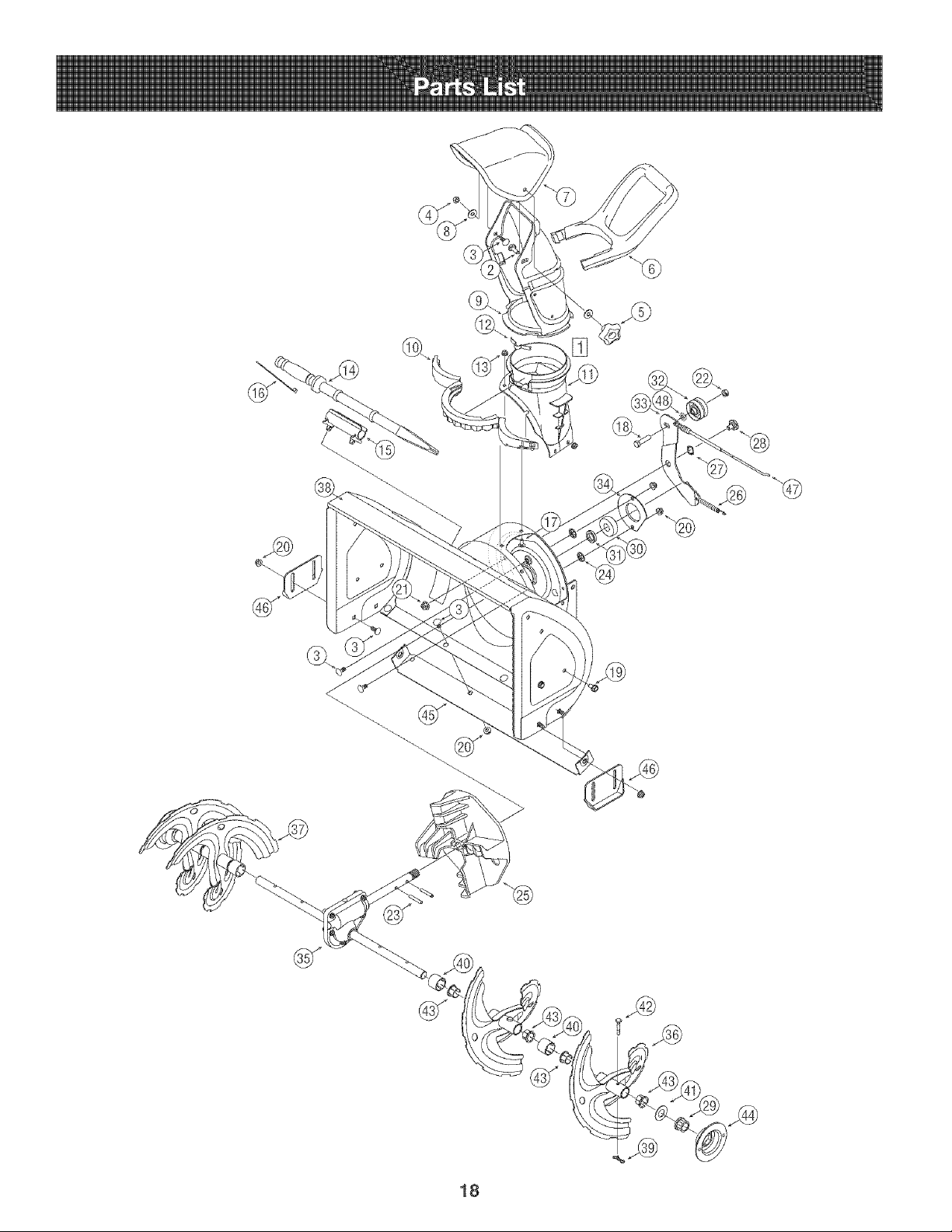
1
2
3
4
5
8
7
8
9
lO
11
12
13
14
15
18
17
18
19
2o
21
22
23
24
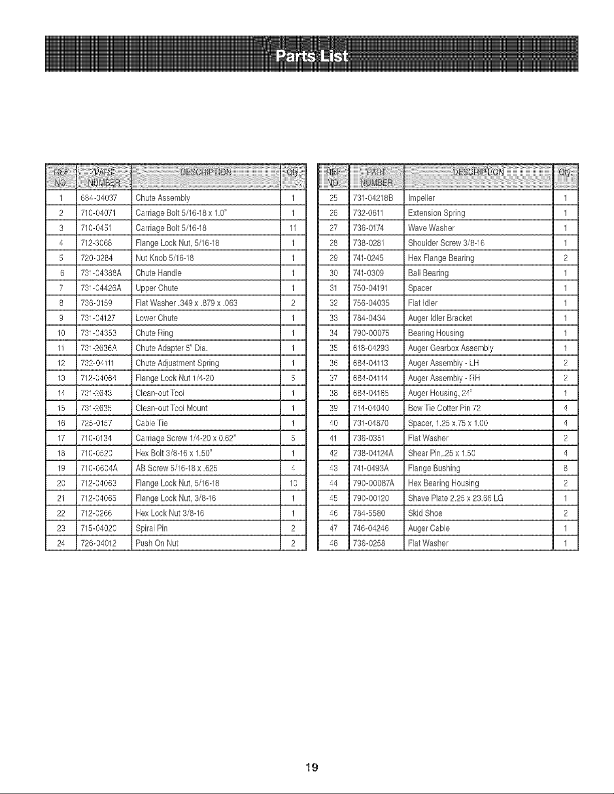
884-04037
71o-o4o71
71o-o451
712-3o88
720-0284
731-04388A
731-04428A
738-0159
731-04127
731-04353
731-2836A
732-04111
712-04084
731-2843
731-2835
725-0157
710-0134
710-0520
710-0604A
712-04063
712-04065
712-0268
715-04020
728-04012
ChuteAssembly
CarriageBolt 5/16-18x 1.0"
CarriageBolt 5/16-18
FlangeLock Nut, 5/16-18
Nut Knob5/16-18
ChuteHandle
UpperChute
FlatWasher.349x .879x .083
LowerChute
ChuteRing
ChuteAdapter5" Dia.
ChuteAdjustmentSpring
FlangeLock Nut 1/4-20
Clean-outTool
Clean-outTool Mount
CableTie
CarriageScrew1/4-20x 0.62"
HexBolt 3/8-16x 1.50"
AB Screw5/18-18x .825
FlangeLock Nut, 5/16-18
FlangeLock Nut, 3/8-16
HexLock Nut 3/8-16
SpiralPin
PushOn Nut
1 25 731-04218B
1 28 732-0811
11 27 738-0174
1 28 738-0281
1 29 741-0245
1 30 741-0309
1 31 750-04191
2 32 758-04035
1 33 784-0434
1 34 790-00075
1 35 618-04293
1 38 884-04113
5 37 884-04114
1 38 684-04165
1 39 714-04040
1 40 731-04870
5 41 736-0351
1 42 738-04124A
4 43 741-0493A
10 44 790-00087A
1 45 790-00120
1 48 784-5580
2 47 746-04248
2 48 736-0258
Impeller
ExtensionSpring
WaveWasher
Shoulder Screw3/8-16
HexFlangeBearing
BallBearing
Spacer
FlatIdler
Auger IdlerBracket
BearingHousing
Auger GearboxAssembly
AugerAssembly- LH
AugerAssembly- RH
Auger Housing,24"
BowTie CotterPin 72
Spacer,1.25x.75 x 1.00
FlatWasher
Shear Pin,.25x 1.50
FlangeBushing
HexBearingHousing
Shave Plate2.25 x 23.86LG
Skid Shoe
AugerCable
FlatWasher
1
1
1
1
2
1
1
1
1
1
1
2
2
1
4
4
2
4
8
2
1
2
1
1
19
[]
@
20
iiiii:ii @i !i!ii!i!i,i
iiiiiii@ !i!'ii'ii'ii'iiiiii:i i
1
2
3
4
5
6
7
8
9
lO
11
12
13
14
15
16
17
18
19
2o
21
22
23
24
25
26
27
28
29
3o
31
32
33
34
35
36
37
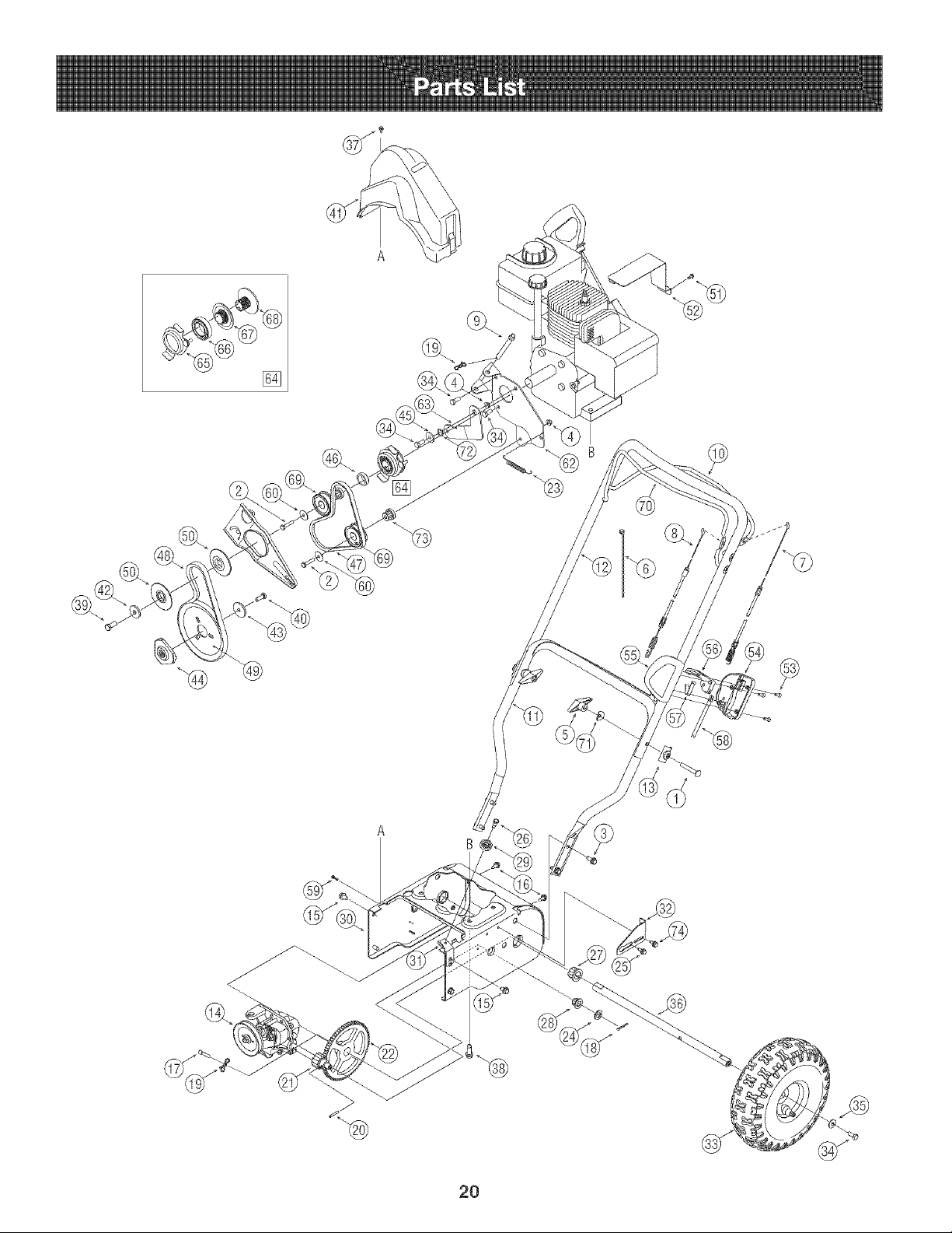
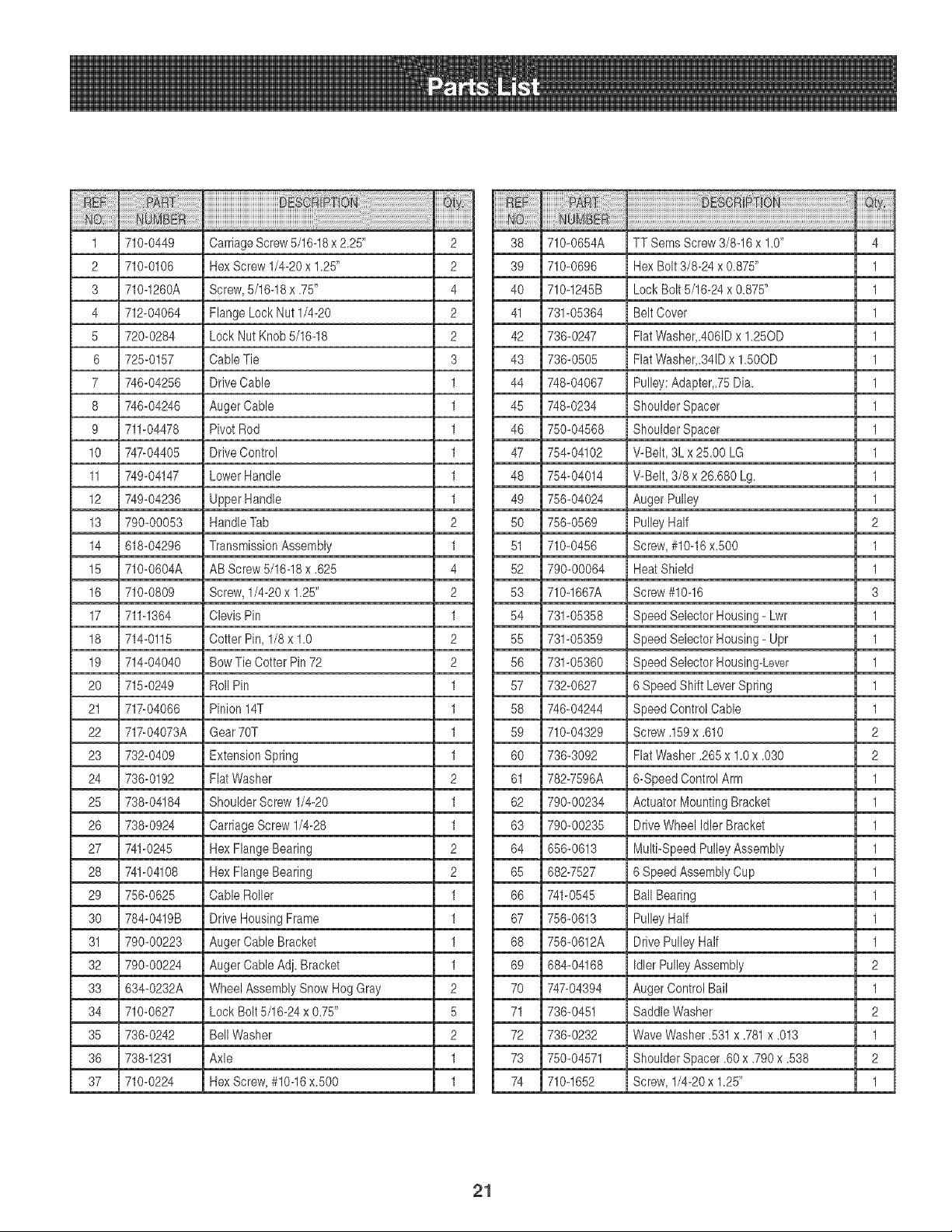
71o-o449 CarriageScrew5/16-18x 2.25" 2
710-0106 HexScrew1/4-20x 1.25" 2
710-1260A Screw,5/16-18x .75" 4
712-04064 FlangeLockNut 1/4-20 2
720-0284 Lock NutKnob 5/16-18 2
725-0157 Cable Tie 3
746-04256 DriveCable 1
746-04246 AugerCable 1
711-04478 PivotRod 1
747-04405 DriveControl 1
749-04147 LowerHandle 1
749-04236 UpperHandle 1
790-00053 HandleTab 2
618-04296 TransmissionAssembly 1
710-0604A AB Screw 5/16-18x .625 4
710-0809 Screw,1/4-20x 1.25" 2
711-1364 Clevis Pin 1
714-0115 Cotter Pin, 1/8x 1.0 2
714-04040 BowTie Cotter Pin 72 2
715-0249 Roll Pin 1
717-04066 Pinion14T 1
717-04073A Gear70T 1
732-0409 ExtensionSpring 1
736-0192 FlatWasher 2
738-04184 ShoulderScrew 1/4-20 1
738-0924 CarriageScrew1/4-28 1
741-0245 HexFlangeBearing 2
741-04108 HexFlangeBearing 2
756-0625 Cable Roller 1
784-0419B DriveHousingFrame 1
790-00223 AugerCable Bracket 1
790-00224 AugerCable Adj. Bracket 1
634-0232A Wheel AssemblySnow Hog Gray 2
710-0627 Lock Bolt5/16-24x 0.75" 5
736-0242 BellWasher 2
738-1231 Axle 1
710-0224 HexScrew,#10-16x.500 1
38
39
4O
41
42
43
44
45
46
47
48
49
5O
51
52
53
54
55
56
57
58
59
6O
61
62
63
64
65
66
67
68
69
70
71
72
73
74
710-0654A
710-0696
710-1245B
731-05364
736-0247
736-0505
748-04067
748-0234
750-04568
754-04102
754-04014
756-04024
756-0569
710-0456
790-00064
710-1667A
731-05358
731-05359
731-05360
732-0627
746-04244
710-04329
736-3092
782-7596A
790-00234
790-00235
656-0613
682-7527
741-0545
756-0613
756-0612A
684-04168
747-04394
736-0451
736-0232
750-04571
710-1652
TT SeresScrew3/8-16x 1.0" 4
HexBolt 3/8-24 x 0.875" 1
Lock Bolt 5/16-24x 0.875" 1
Belt Cover 1
FlatWasher,.4061Dx 1.25OD 1
FlatWasher,34JDx 1.50OD 1
Pulley:Adapter,75Dia. 1
ShoulderSpacer 1
ShoulderSpacer 1
V-Belt, 3L x25.00 LG 1
V-Belt, 3/8 x 26.680 Lg. 1
AugerPulley 1
PulleyHalf 2
Screw,#10-16x.500 1
Heat Shield 1
Screw#10-16 3
SpeedSelectorHousing- Lwr 1
SpeedSelectorHousing- Upr 1
SpeedSelectorHousing_Lever 1
6 SpeedShiftLeverSpring 1
SpeedControl Cable 1
Screw.159x .610 2
FlatWasher.265x 1.0x .030 2
6-SpeedControlArm 1
Actuator MountingBracket 1
DriveWheel IdlerBracket 1
Multi-SpeedPulleyAssembly 1
6 SpeedAssemblyCup 1
BallBearing 1
PulleyHalf 1
DrivePulley Half 1
IdlerPulley Assembly 2
Auger ControlBail 1
SaddleWasher 2
WaveWasher.531x .781x .013 1
ShoulderSpacer.60x .790x .538 2
Screw,1/4-20x 1.25" 1
21
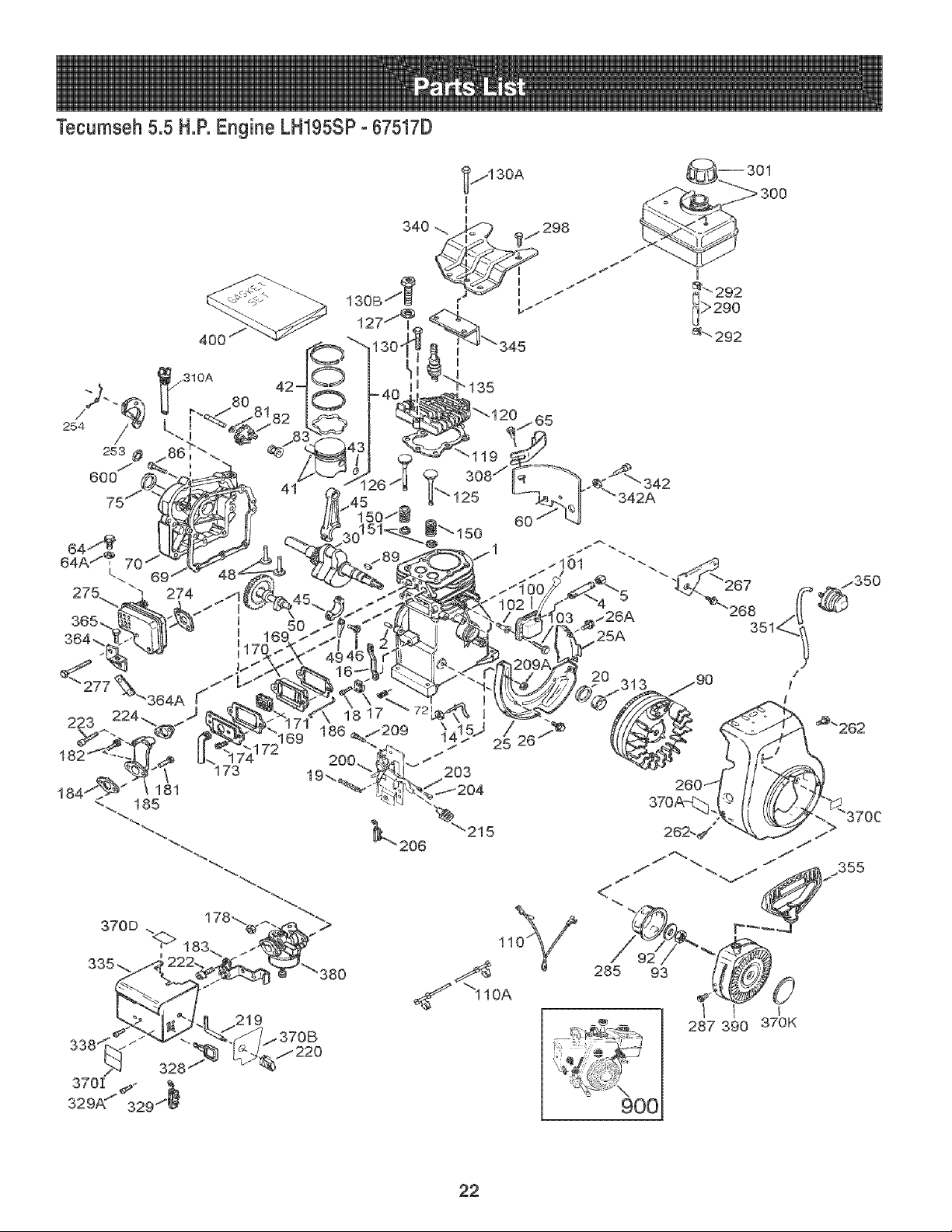
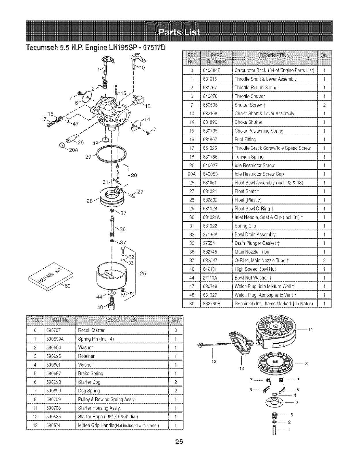
Tecumseh 5.5 H.R Engine LH195SPo67517D
400
310A
;;--,e
254 //
253 #
600
i
I
_._" 292
_>290
_" 292
22
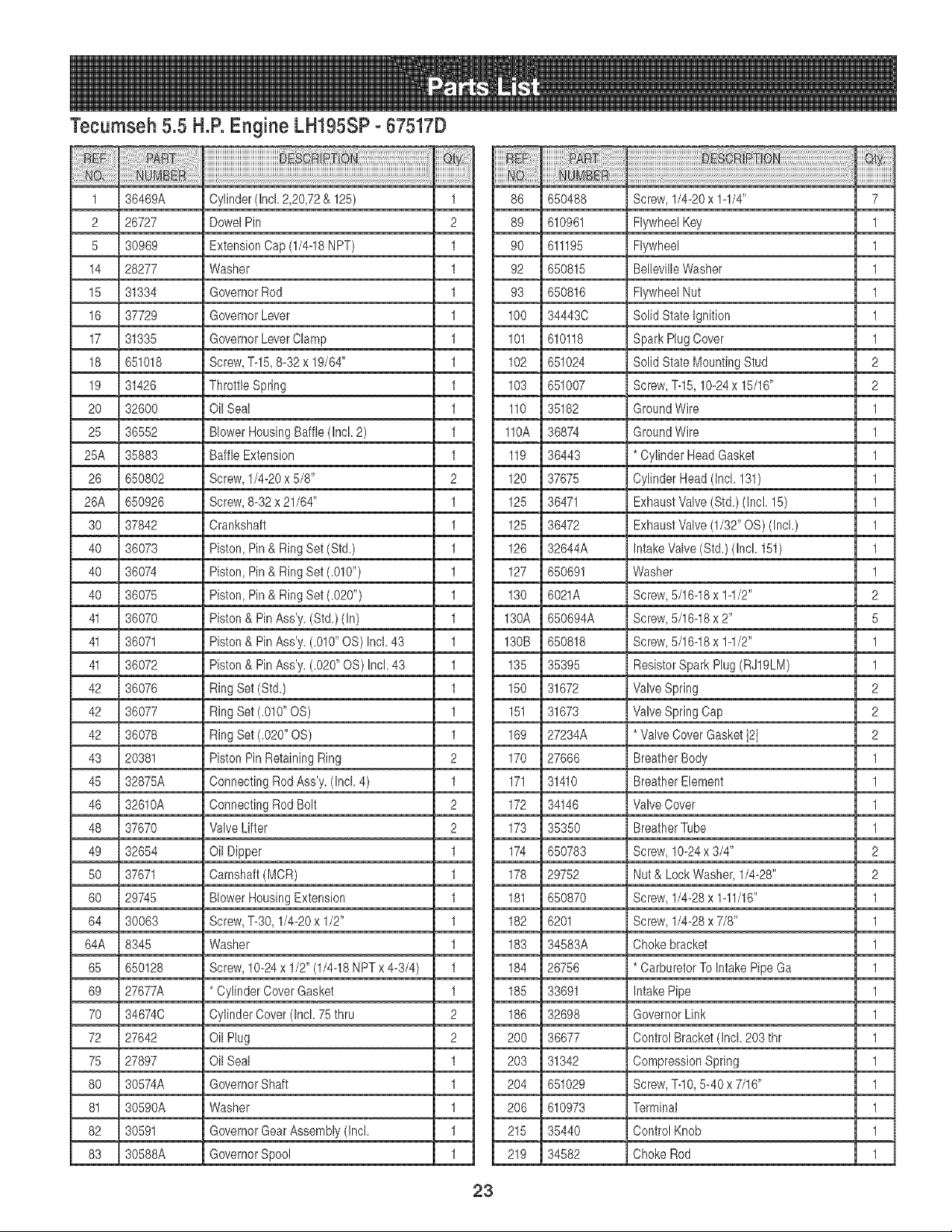
Tecumseh 5.5 H.P.Engine LH195SP- 67517D
iiiiiily!ii!i!!i ill
1 36469A Cylinder(Incl.2,20,72& 125) 1
2 26727 DowelPin 2
5 30969 ExtensionCap (1/4-18NPT) 1
14 28277 Washer 1
15 31334 GovernorRod 1
16 37729 GovernorLever 1
17 31335 GovernorLeverClamp 1
18 651018 Screw,T-15,8-32 x 19/64" 1
19 31426 ThrottleSpring 1
20 32600 Oil Seal 1
25 36552 BlowerHousingBaffle(Incl. 2) 1
25A 35883 BaffleExtension 1
26 650802 Screw,1/4-20x 5/8" 2
26A 650926 Screw,8-32 x 21/64" 1
30 37842 Crankshaft 1
40 36073 Piston,Pin& RingSet (Std.) 1
40 36074 Piston,Pin& RingSet (.010") 1
40 36075 Piston,Pin& RingSet (.020") 1
41 36070 Piston& PinAss'y.(Std.)(In) 1
41 36071 Piston& PinAss'y.(.010"OS) Incl.43 1
41 36072 Piston& PinAss'y.(.020"OS) Incl.43 1
42 36076 RingSet (Std.) 1
42 36077 RingSet (.010"OS) 1
42 36078 RingSet (.020" OS) 1
43 20381 PistonPin RetainingRing 2
45 32875A ConnectingRodAss'y. (1rick4) 1
46 32610A ConnectingRod Bolt 2
48 37670 Valve Lifter 2
49 32654 Oil Dipper 1
50 37671 Camshaft(MCR) 1
60 29745 BlowerHousingExtension 1
64 30063 Screw,T-30, 1/4-20x 1/2" 1
64A 8345 Washer 1
65 650128 Screw,10-24x 1/2"(1/4-18NPT x 4-3/4) 1
69 27677A * CylinderCoverGasket 1
70 34674C CylinderCover(Incl. 75thru 2
72 27642 Oil Plug 2
75 27897 Oil Seal 1
80 30574A GovernorShaft 1
81 30590A Washer 1
82 30591 GovernorGearAssembly(Incl. 1
83 30588A GovernorSpool 1
86
89
9O
92
93
100
101
102
103
110
110A
119
120
125
125
126
127
130
130A
130B
135
150
151
169
170
171
172
173
174
178
181
182
183
184
185
186
2OO
203
2O4
206
215
219
23
650488
610961
611195
650815
650816
34443C
610118
651024
651007
35182
36874
36443
37675
36471
36472
32644A
650691
6021A
650694A
650818
35395
31672
31673
27234A
27666
31410
34146
35350
650783
29752
650870
6201
34583A
26756
33691
32698
36677
31342
651029
610973
35440
34582
Screw,1/4-20x 1-1/4"
FlywheelKey
Flywheel
BellevilleWasher
FlywheelNut
SolidState Ignition
Spark PlugCover
SolidState MountingStud
Screw,T-15,10-24x 15/16"
GroundWire
GroundWire
* CylinderHeadGasket
CylinderHead(Incl.131)
ExhaustValve(Std.) (Incl. 15)
ExhaustValve(1/32" OS) (Incl.)
IntakeValve(Std.) (Incl. 151)
Washer
Screw,5/16-18x 1-1/2"
Screw,5/16-18x 2"
Screw,5/16-18x 1-1/2"
ResistorSpark Plug(RJ19LM)
Valve Spring
Valve SpringCap
*Valve CoverGasket121
BreatherBody
BreatherElement
Valve Cover
BreatherTube
Screw,10-24x 3/4"
Nut& LockWasher,1/4-28"
Screw,1/4-28x 1-11/16"
Screw,1/4-28x 7/8"
Chokebracket
* CarburetorTo IntakePipe Ga
IntakePipe
GovernorLink
ControlBracket (Incl.203thr
CompressionSpring
Screw,T-1O,5-40 x 7/16"
Terminal
ControlKnob
ChokeRod
7
1
1
1
1
1
1
2
2
1
1
1
1
1
1
1
1
2
5
1
1
2
2
2
1
1
1
1
2
2
1
1
1
1
1
1
1
1
1
1
1
1
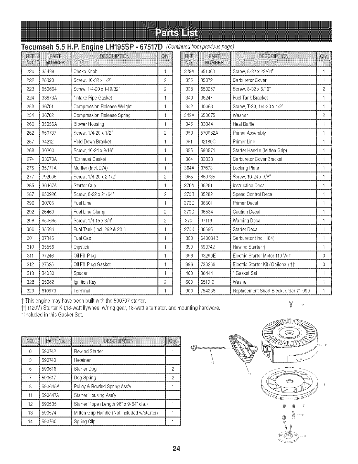
Tecumseh 5.5 H.R iine LH195SP- 67517D (Continuedfrompreviouspage)
220 35438 ChokeKnob 1 329A 651060 Screw,8-32 x 23/84" 1
222 28820 Screw,10-32x 1/2" 2 335 35072 CarburetorCover 1
223 650684 Screw,1/4-20x 1-19/32" 2 338 650257 Screw,8-32 x 5/18" 2
224 33873A *Intake Pipe Gasket 1 340 36247 FuelTankBracket 1
253 36701 CompressionReleaseWeight 1 342 30063 Screw,T-30, 1/4-20x 1/2" 1
254 36702 CompressionReleaseSpring 1 342A 650675 Washer 2
260 35858A BlowerHousing 1 345 33344 Heat Baffle 1
282 650737 Screw,1/4-20x 1/2" 2 350 570882A PrimerAssembly 1
287 34212 HoldDownBracket 1 351 32180C PrimerLine 1
268 30200 Screw,10-24x 9/16" 1 355 590574 Starter Handle(Mitten Grip) 1
274 33870A *Exhaust Gasket 1 384 33333 CarburetorCoverBracket 1
275 35771A Muffler(Incl. 274) 1 364A 37673 LockingPlate 1
277 792005 Screw,1/4-20x 2-1/2" 2 385 650735 Screw,10-24x 3/8" 1
285 36467A StarterCup 1 370A 36261 InstructionDecal 1
287 650926 Screw,8-32x 21/64" 2 370B 35282 SpeedControl Decal 1
290 30705 FuelLine 1 370C 36501 PrimerDecal 1
292 26460 FuelLineClamp 2 370D 36534 CautionDecal 1
298 650665 Screw,1/4-15x3/4" 2 370! 37119 WarningDecal 1
300 35584 FuelTank (Incl.292 & 301) 1 370K 36695 Starter Decal 1
301 37845 FuelCap 1 380 640084B Carburetor(Incl. 184) 1
310 35558 Dipstick 1 390 590742 RewindStartert 1
311 37248 Oil FillPlug 1 398 33290E Electric Starter Motor110Volt 0
312 27825 Oil FillPlug Gasket 1 398 730266 Electric StarterKit (Optional) 11 0
313 34080 Spacer 1 400 36444 * GasketSet 1
328 35062 IgnitionKey 2 800 651013 Washer 1
329 610973 Terminal 1 900 754336 ReplacementShort Block, order71-999 1
t This enginemayhavebeen builtwiththe 590707starter.
ff (12ov)StarterKit,18-wattflywheelw/ring gear,18-wattalternator,
* Includedin thisGasketSet.
0 590742 RewindStarter 1
3 590740 Retainer 1
8 590618 StarterDog 2
7 590617 DogSpring 2
8 590645A Pulley& RewindSpring Ass'y 1
11 590647A Starter HousingAss'y 1
12 590535 StarterRope(Length 98" x 9/64" dia.) 1
13 590574 MittenGrip Handle(Not includedw/starter) 1
14 590780 SpringClip 1
andmountinghardware.
13
..... 8
24
Tecumseh 5.5 H.R Engine LH195SP- 67517D
o
1
2
3
4
5
6
7
8
11
12
13
590707 RecoilStarter
590599A SpringPin (Incl.4)
590600 Washer
590696 Retainer
590601 Washer
590697 Brake Spring
590698 Starter Dog
590699 Dog Spring
590709 Pulley & RewindSpring Ass'y.
590708 Starter HousingAss'y.
590535 Starter Rope ( 98" X 9/64"dia.)
590574 Mitten GripHandle(Notincludedwithstarter}
0
1
1
1
1
1
2
2
1
1
1
1
25
o
1
2
6
7
lO
14
15
16
17
18
2o
20A
25
27
28
29
3O
31
32
33
36
37
40
44
47
48
6O
640084B Carburetor(Incl. 184of EngineParts List)
631615 ThrottleShaft & LeverAssembly
631767 Throttle ReturnSpring
640070 ThrottleShutter
650506 ShutterScrewt
632108 ChokeShaft & LeverAssembly
631890 ChokeShutter
630735 Choke PositioningSpring
631807 FuelFitting
651025 ThrottleCrack Screw/IdleSpeed Screw
630766 TensionSpring
640027 Idle RestrictorScrew
640053 Idle RestrictorScrewCap
631951 FloatBowl Assembly(Incl. 32 & 33)
631024 FloatShaft t
632802 Float(Plastic)
631028 FloatBowl O-Ring1
631021A InletNeedle,Seat& Clip (Incl. 31)1
631022 Spring Clip
27136A BowlDrainAssembly
27554 Drain PlungerGasket1
632745 MainNozzleTube
632547 O-Ring,MainNozzleTube1
640131 HighSpeedBowlNut
27110A BowlNutWasher1
630748 Welch Plug,Idle MixtureWell t
631027 Welch Plug,AtmosphericVentt
632760B Repairkit (Incl. Items Marked1 inNotes)
13 @--8
6
1
1
1
1
2
1
1
1
1
1
1
1
1
1
1
1
1
1
1
1
1
1
2
1
1
1
1
1

26
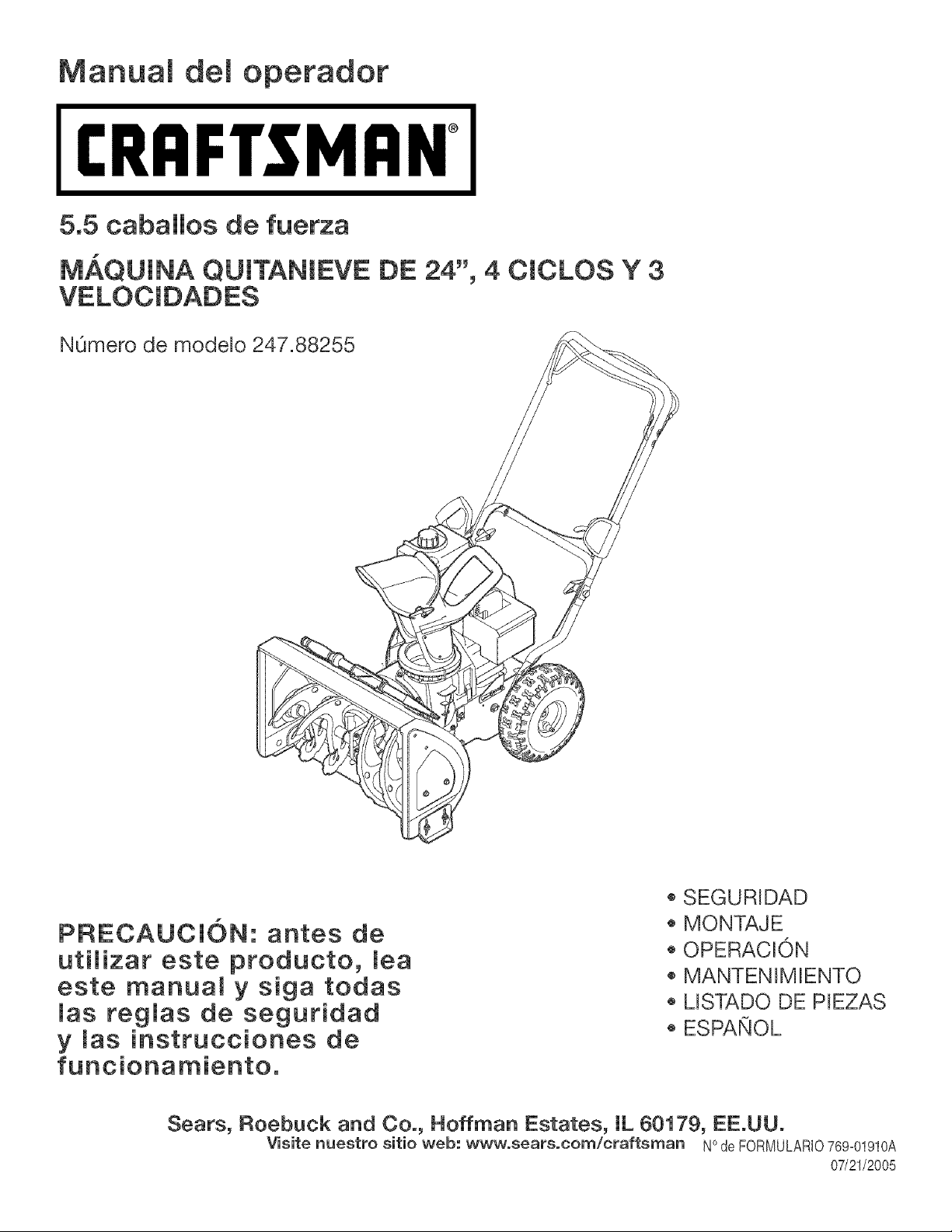
Manuam demoperador
CRAFTSMAN°
5.5 caballos de fuerza
M_,QUINA QUmTANIEVE DE 24", 4 CICLOS Y 3
NOmero de modelo 247.88255
PRECAUCI(DN: antes de
uti_izar este producto, mea
este manual y siga todas
mas regmas de seguridad
y mas instrucciones de
funcionamiento,
o SEGURRDAD
MONTAJE
OPERACION
MANTENIMENTO
MSTADO DE PEZAS
ESPANOL
Sears, Roebuck and Co., Hoffman Estates, IL 60179, EE.UU.
Visite nuestro sitio web: www.sears.corn/craftsman NOde FORNULARIO769_01910A
07/21/2005
Deciaraci6ndegarantia...........................PSgina2
Etiquetasdeseguridad............................PSgina3
Regiasdeoperaci6nsegura...................PSginas4-5
Configuraci6ny ajuste.............................PSginas6-7
ConozcasumSquinaquitanieve.............PSgina8-9
Operaci6n.................................................PSgina10-11
Mantenimientoy servicio......................Pagina12-15
AImacenamientofueradetemporadaysoluci6nde
problemas................................................PSgina16-17
Nqmerodeservicio...........................Cubiertaposterior
Garantiadedosariesparalam_quinaquitanbveCraftsman
Durantedosahosapartirdelafechadecompra,siemprequeaestam&quinaquitanieveselerealiceelserviciodemantenimiento,lubrbacbn
ypuestaapuntodeacuerdoalasinstruccionesdelmanualdelpropietario,SearsrepararAsincargocualqubrdefectodemateriabsomanode
obra.SiestamAquinaquitanieveCraftsmanseutilizaparaprop6sitoscomerciabsodealquiler,estagaranfiaseaplicas61odurante30diasa
partirdelafechadecompra.Estagarantianocubre:
• Ebmentosdesechabbsquesedesgastanperel usonormal,incluyendoentreotros,zapatasantideslizantes,placade raspadoy buifas.
Reparacionesnecesariasdebidoa abusoo negligenciadeloperador,incluyendoabolladuradel cigOehaly falla pornorealizarmantenimiento
delequipode acuerdocon las instruccionescontenidasenel manualdel propbtario.
EL SERVlCIODEGARANT[AESTADISPONiBLEPARALOSUSUARIOSQUELLEVENLA MAQUINAQUITANiEVECRAFTSMANAL
CENTRODE PARTESy REPARAClONSEARSMASCERCANODENTRODELOS ESTADOSUNIDOS.
Estagarantiaes validaOnicamentembntras el pro@do se utilicedentrode los EstadosUnidos.
PARAUBICAREL CENTRODE PARTESY REPARACiONSEARSM/_,SCERCANO0 PARAPROGRAMAREL SERVlCIOTECNICO,SIMPLE-
MENTECOMUNiQUESECON SEARSAL TELEFONO1-800-4-MY-HOME@.
Estagaranfiale otorgaderechoslegabs especfficos;usted tambienpuedetenerotrosderechos,los cuabs variande unestadoa otro.
SEARS,ROEBUCKAND CO., D/817WA,HOFFMANESTATES,IL 60179
Acuerdos de protecci6n sobre reparaciones
Felicitacionespor haberrealizadouna adquisici6n[nteligente,El
productoCraftsman@queha adquiridoestadisehadoy fabricadopara
brindarmuchosahosde funcionambntoconfiabb,
Perocomotodoslos productosa vecespuederequerirderepara-
clones,Esen esemomentocuandoel disponerde unacuerdode
protecci6nparareparacionesle puedeahorrardineroy probbmas,
A continuaci6nsedetallanlos puntos[ncluidosen elacuerdo:
, Servb[oexpertoprestadopernuestros12,000especialistasen
reparacionesprofesionabs
, Servbio [limitadosincargo paralas pbzas y la manede obraen
todaslas reparacionescubbrtas
, Reemplazodelproductos[ no esposibbrepararel productocubbrto
• Descuentode 10%delprec[onormaldel servb[o y de laspbzas
relacionadascon el mismoque no esten cubbrtas perel acuerdo;
ademb,s, 10%de descuentodel prec[onormalde la verificaci6nde
mantenimientopreventive
, Ayudar@idaporteldono- asistenciatebf6nicaa cargode un
t6cnicode Searspara losproductosquerequbren reparaci6na
domicil[o,adem_,sde unaprogramaci6nconvenbnteparalarepara-
c[6n,Adqubraahoraun acuerdode protecci6npara reparacionesy
prot6iasede probbmasy gastos[nesperados
Unavez adquiridoel acuerdo,puedeprogramarel servb[o con
tan s61orealizaruna Ilamadatelef6niea,PuedeIlamarencualquier
momentodel d[a o de la noche,o programarun servicioen linea.
Searsdisponedem_sde 12,000espeeialistasenreparaeiones
profesionabsque tienenaceesoa m_sde4,5 millonesdepiezas
y aceesoriosde gran ealidad,Este esel fipo de profesiona%moen
el quepuedeeonfiarparaque le ayudeaprolongarlavida 0til del
productorecientementeadquiridoenlos ahos porvenir,iAdquierahoy
su aeuerdodeprotecei6nparareparaciones!
Se aplican determinadas limitaciones y exelusiones. Paraobtener
precios e informaci6nadicional llameal 1-800-827o6655.
Servicio de instalaei6n de Sears
Sideseasolicitarla instalaci6nprofesionalde Searsde @arabs
dom6sticos,dispositivosparaabrir portones,calentadoresde aguay
otrosar%ulos domesticosimportantes,en losEstadosUnidosIlame
al 1-800-4-MY-HOME@
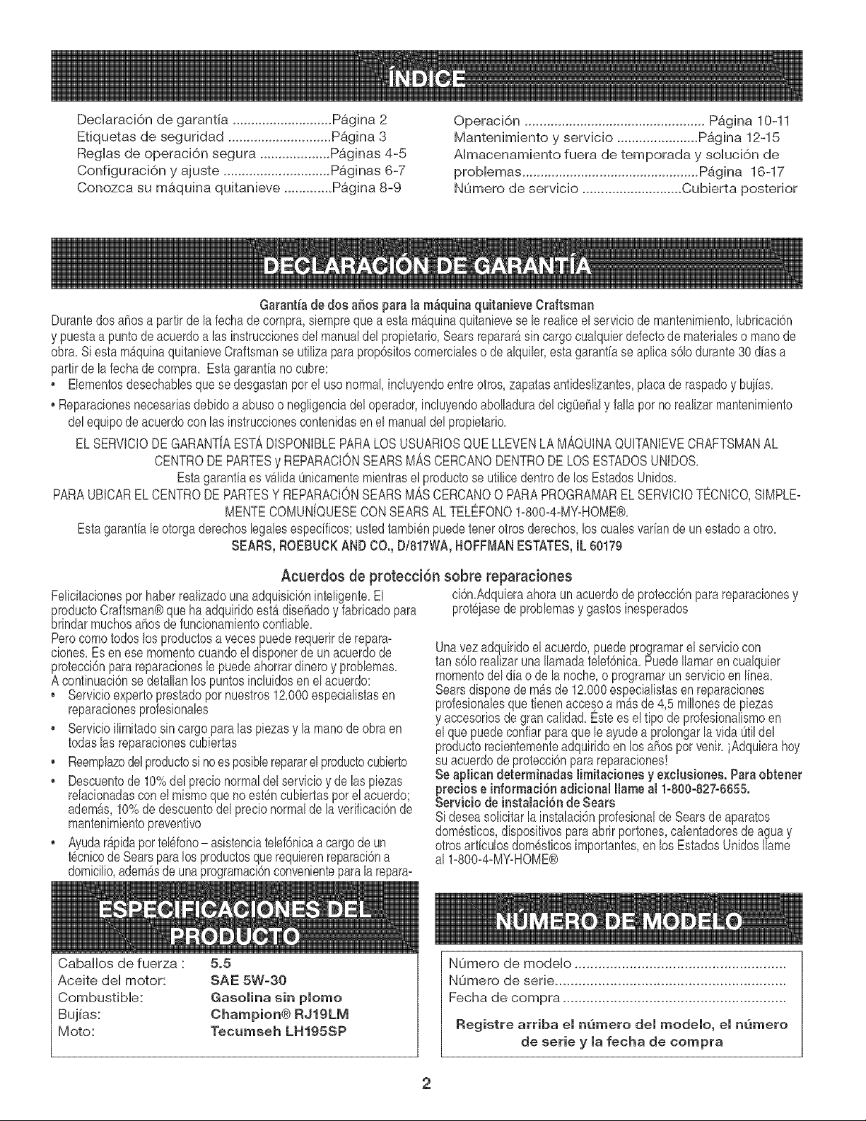
Cabaiios de fuerza :
Aceite del motor:
Combustible:
Bujias:
Moto:
5.5
SAE 5W=30
Gasolina sin plomo
Champion@ RJ19LIVI
Tecumseh LH195SP
NOmero de modeio ......................................................
NOmero de serie ...........................................................
Fecha de compra .........................................................
Registre arriba el nQmero del modelo, el nw3mero
de serie y la fecha de compra
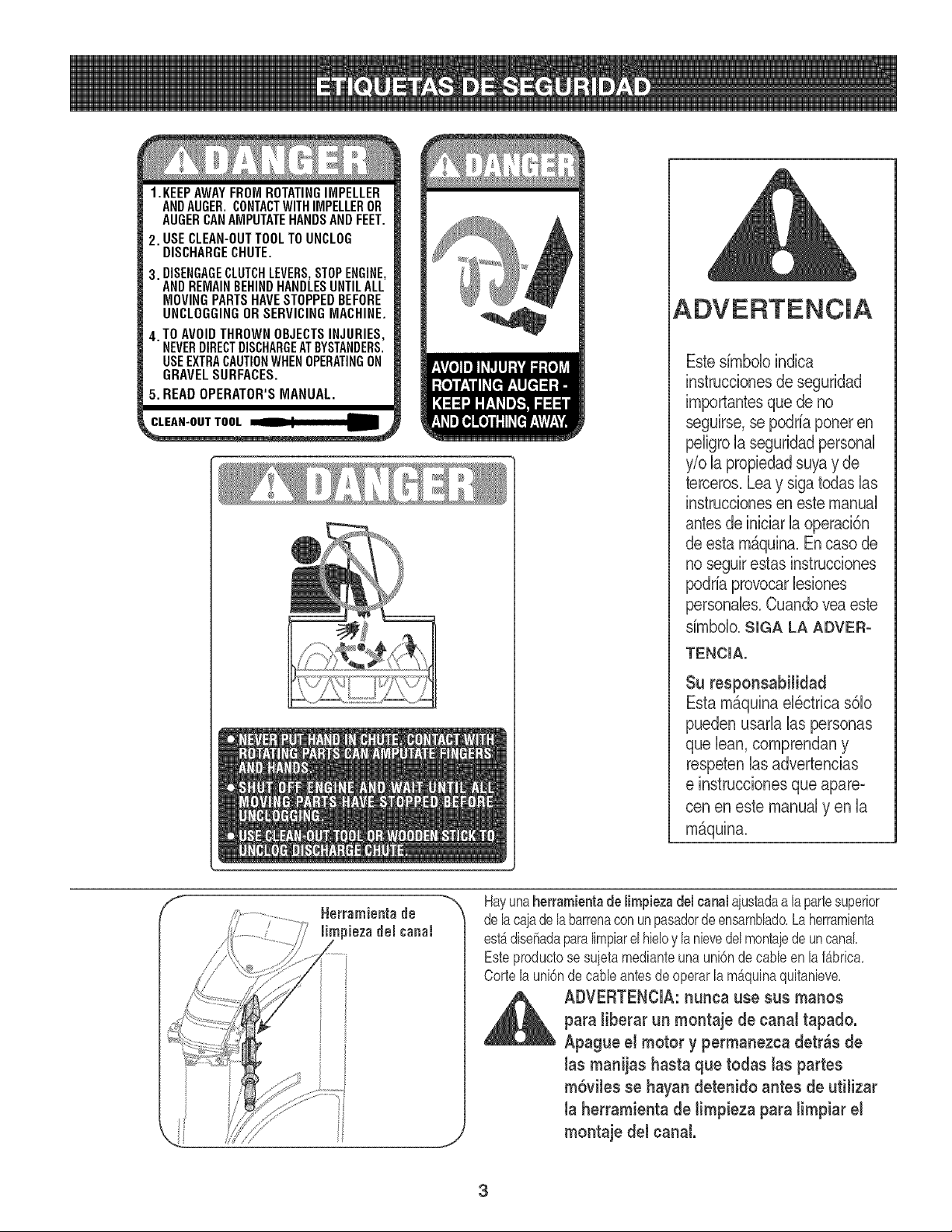
1.KEEPAWAYFROMROTATINGIMPELLER
ANDAUGER.CONTACTWITHIMPELLEROR
AUGERCANAMPUTATEHANDSANDFEET,
2. USECLEAN-OUTTOOLTOUNCLOG
DISCHARGECHUTE.
3. DISENGAGECLUTCHLEVERS,STOPENGINE,
ANDREMAINBEHINDHANDLESUNTILALL
MOVINGPARTSHAVESTOPPEDBEFORE
UNCLOGGINGOR SERVICINGMACHINE,
4. TO AVOIDTHROWNOBJECTSINJURIES,
NEVERDIRECTDISCHARGEATBYSTANDERS.
USEEXTRACAUTIONWHENOPERATINGON
GRAVELSURFACES.
5. READOPERATOR'SMANUAL.
Estesimbolo indica
instrucdones de seguridad
importantesque de no
seguirse,se podria poneren
peligrola seguridadpersonal
y/o b propiedadsuyay de
terceros.Lea y siga todas bs
instrucdones en este manual
antes de iniciarb operacbn
de esta m_quina.Encaso de
no seguirestas instrucdones
podrb provocar bsiones
personales.Cuandovea este
simbolo.SIGA LA ADVER-
TENCIA.
Su responsabitidad
Esta maquina el_ctrica s61o
pueden usarb bs personas
que lean, comprendan y
respetenbs advertencias
e instruccionesque @are °
cen en este manual y en la
maquina.
f
%
J
Hayunaherrarnientade lirnpiezadel canalaiustadaa lapartesuperior
delacajade la barrenacon unpasadordeensamblado,La herramienta
estadisehadaparalimpiarelhieloy b nievedel montaiede uncanal,
Esteproductose suietamedianteunaunbn de cane en lafabric&
Cortela uni6ndecane antesdeoperarlamAquinaquitanieve,
_lb DVERTENCIA: nunca use sus manos
para liberar un montaje de canal tapado.
Apague el motor y permanezca detr_s de
las manijas hasta que todas tas partes
m6viles se hayan detenido antes de utilizar
la herramienta de limpieza para limpiar el
montaje del canal.
3
DVERTENCIA:elescapedelmotordeesteproducto,algunosdesuscomponentesy algunoscompo-
nentesdelvehiculocontienenoemitenproductosquimicosqueelestadodeCaliforniaconsideraque
puedenproducirc£ncer,defectosdenacimientou otrosproblemasreproductivos.
PELIGRO:: estamaquinaestadiseiadaparaserutilizadarespetandolasreglasdeseguridadcontenidaseneste
manual.AIigualqueconcualquiertipodeequipoel_ctrico,undescuidoo errorperpartedeloperadorpuedeproducir
lesionesgraves.Estamaquinaescapazdeamputarmanosy piesy dearrojarobjetoscongranfuerza.Denorespetarlas
instruccionesdeseguridadsiguientessepuedenproducirlesionesgraveso lamuerte.
ADVERTENCIA:estesimboloindicainstruccionesdeseguridadimportantesquedenoseguirse,se
podriaponerenpeligrola seguridadpersonaly/olapropiedadsuyay deterceros.Leay sigatodaslas
instruccionesenestemanualantesdeiniciarlaoperaci6ndeestamaquina.Encasodenoseguirestas
instruccionespodriaprovocarlesionespersonales.CuandoyeaestesimboloSIGALAADVERTENOIA.
Suresponsablidad:estam£quinael6ctricas61opuedenusarlalaspersonasquelean,comprendany respetenlasad-
vertenciase instruccionesqueaparecenenestemanualy enlamaquina.
Preparativos
1. Inspeccioneminuciosamenteel £readonde utilizar£elequipo.Saquetodos
losfelpudos,peri6dicos,trineos,tablas,cablesy otrosobjetosextraF_oscon
los quepodr[atropezaro que podrianser arrojadosporla barrena/ motor.
2. Paraprotegerselos ojosutilice siempreanteojoso antiparrasde
seguridadmientrasopera la maquinao mientrasla ajustao repara.Los
objetos arrojadosque rebotanpuedenlesionargravementelavista.
3. Nooperela m£quinasinla vestimentaadecuada paraestaral aire libre en
invierno.[to utilicealhajas,bufandaslargasu otras prendassueltasque
podrian enredarseenlas partesmoviles.Utilice un calzadoespecialpara
superficiesresbaladizas.
4. Useun prolongadory untomacorrientede tres cablescon conexiona
tierra paratodas las unidadescon motoresde encendidoelectrico.
5. Ajuste laaltura de la caja del tomacorrientepara limpiarla gravao las
superficiescon piedrastrituradas.
6. Desengranetodas laspalancas de controlantes de arrancarel motor.
7. Nuncaintenterealizarajustesmientrasel motorest£ en marchaexcepto
en loscasos especlicamente recomendadosen el manualdel operador.
8. Dejequeel motory la maquinaseadaptena la temperaturaexteriorantes
de comenzara sacarla nieve.
9. Paraevitarlesionespersonaleso daF_osmaterialessea sumamente
cuidadosoal manipularlagasolina. La gasolinaes altamenteinflamabley
sus vaporespuedencausarexplosiones.Se puedelesionar gravemente
si derramagasolinasobre ustedo sobre la ropaya quese puede prender
fuego.Lavesela piely cambiesede ropa de inmediato.
a. Utilices61orecipientespara gasolinaautorizados.
b. Apaguetodosloscigarrillos,cigarros,pipasy otrasfuentesdecombusti6n.
c. Nuncacarguecombustibleen la maquinaen un espaciocerrado.
d. Nuncasaque la tapa del gas niagreguecombustiblemientrasel motor
est£ calienteo en marcha.
e. Dejeque el motorse enfr[eper Io menosdos minutesantesde volvera
cargar combustible.
f. Nuncarecargueel tanquede combustible.Lleneel tanqueno m;Jsde
1/2pulgadapor debajode la basedel cuello delfiltro paradejar espacio
para la dilataci6ndel combustible.
g. Vuelvaa colocar latapa de lagasolinay aj£stelabien.
h. Limpiela gasolinaderramadasobre el motory elequipo. Trasladela
m£quinaa otra zona. Espere5 minutosantesde encenderel motor.
i. Nuncaalmacenela m£quinao el recipientede combustibleen un
espaciocerrado dondehayafuego,chispaso luzpiloto (por ejemplo,
hornos,calentadoresde agua, calefactores,secadoresde ropa,etc.).
j. Dejequela m£quinase enfr[eperIo menos5 minutosantesde guardarla
Capacitaci6n
1. Lea,entienday cumplatodaslas instruccionesincluidasen la maquinay
en los manualesantes de montarlay utilizarla.Guardeestemanualen un
lugarseguroparaconsultasfuturasy regulares,as[ comepara solicitar
repuestos.
2. Familiaricesecon todoslos controlesy su funcionamientoapropiado.Sepa
comodetenerla m£quinay comodesengranarloscontrolesrapidamente.
3. Nopermitanuncaquelos niF_osmenoresde 14 afrosutilicenesta m£quina.
Los nJ_osde 14 a_osy masmayoresdebenleery comprenderlas
instruccionesde funcionamientoy las reglasde seguridadcontenidasen
estemanual,ytambiendebenser capacitadosy estar supervisadospor
unode lospadres.
4. Nuncapermitaquelos adultosutilicenestam£quinasin recibirantes la
instrucci6napropiada.
5. Losobjetosarrojadospor la m;Jquinapuedenproducirlesionesgraves.
Planifiqueel patronen el queva a ir arrojandonieveparaevitarque la
descargade materialse realicehacialos caminos,los observadores,etc.
6. Mantengaa losobservadores,ayudantes,mascotasy ni_osporIo menosa
75 pies de la maquinamientrasla mismaestAen funcionamiento.Detenga
la maquinasi alguienentraen la zona.
7. Seaprecavidoparaevitarpatinarseocaerse especialmentecuandooperala
maquinaen reversa.
4
Operaci6n
1 No pongalasmanos o los piescerca de las piezasrotatorias,en la caja
de la barrena/ motoro en el montajedel canalde descarga.El contacto
con las piezasrotatoriaspuedeproducirla amputaci6nde manosy pies.
2. Lapalancade control de la barrena/ motores un dispositivode seguri-
dad. Nuncapase poralto sufuncionamiento.De hacerlola operaci6nde
la maquinaes riesgosay puedeocasionarlesiones.
3. Laspalancasde controldebenfuncionarbienenambasdireccionesy
regresarautomaticamentea laposicionde desengranecuandose lassuelta.
4. Nuncaoperela maquinasi faltaun montajedel canalo si el mismoesta
dafiado.Mantengatodos losdispositivosde seguridadensu lugar y en
funcionamiento.
5. Nuncaenciendaun motoren espacioscerradoso en unazonacon poca
ventilaci6n.Elescapedel motorcontienemon6xidode carbono,un gas
inodoroy letal.
6. No utilicela maquinabajo la influenciadel alcoholo lasdrogas.
7. Elsilenciadory el motorse calientany puedenproducir quemaduras.No
lostoque.
8. Seasumamenteprecavidocuandooperela maquinasobre una superficie
con grava o cuandola cruce. Mantengasealerta pot si se presentan
peligrosocultoso transito.
9. Tengacuidado cuandocambiede direcci6n o cuandooperela maquina
en pendientes.
10.Planifiqueel patr6nen el que va air arrojandonieve paraevitar que
la descargade materialse produzcahacialas ventanas,las paredes,
los autom6viles,etc.y evitar as[ posiblesdaflos materialeso lesiones
producidaspor los rebotes.
11.Nuncadirija la descargahacialos niflos, losobservadoresy lasmascotas
ni dejeque nadiese pare delantede la maquina.
12.No sobrecarguela capacidadde la maquinatratandode sacarla nieve
muyrapidamente.
13.Nunca opereestamaquinasin buenavisibilidado iluminaci6n.Siempre
debe estarsegurode queesta bien afirmadoy sostengabien las manijas.
Camine,nuncacorra.
14.Corte lacorrientea la barrena/ motorcuando transportelamaquinao
cuandola mismano esta en uso.
15.Nunca operela maquinaa altavelocidad de desplazamientosobre
superficiesresbaladizas.Mirehacia abajoy haciaatras ytengacuidado
cuandovayamarchaatras.
16.Si la maquinacomenzaraavibrar de maneraanormal,detengael motor,
desconecteel cablede la bujiay p6ngalade maneraque hagamasa
contrael motor.Inspeccionela maquinaminuciosamenteparaver si esta
daflada.Reparetodos los dafiosantes de encendery operarla maquina.
17.Desengranetodas laspalancasde control y detengael motorantesde
dejar la posici6nde operaci6n(detrasde las manijas).Esperea que la
barrena/ motorse detengapor completoantes de destaparel montajedel
canalo realizarajustese inspecciones.
18.Nuncapongalasmanesen lasaberturasde descargao de recolecci6n.
Utilicesiemprela herramientade limpiezaquese adjuntaparadestaparla
aberturade descarga.Nodestapeel montajedelcanalmientrasel motor
estaen funcionamiento.Antesde destaparlo,apagueel motory permanezca
detr4sde las manijashastaquetodaslaspartesm6vilesse hayandetenido.
19.Use s61ounionesy accesoriosaprobadosper elfabricante(perejemplo,
pesaspara las ruedas,cadenasparalos neumaticos,cabinas,etc.).
20.Si se presentansituacionesque noestanprevistasen estemanual,sea
cuidadosoy useel sentidocomOn.Contactecon su centro de servicio
Sears paraobtener ayuda.
Mantenimiento y aimacenamiento
1. Nuncamanipulelosdispositivosde seguridaddemaneraimprudente.
Controleperi6dicamenteque funcionende formaadecuada.Rem[tasea
las seccionesde mantenimientoy ajustede este manual.
2. Antesde realizarlalimpieza,repararo revisarla maquina,desengrane
todas las palancasde controly detengael motor.Esperea que la barrena
/ motorse detengapercompleto.Desconecteel cable de la buj[ay
p6ngalode maneraque hagamasacontra el motorparaevitar quese
enciendade maneraaccidental.
3. Controlefrecuentementequetodos los pernosy tornillosesten bien
ajustadosparacomprobarquela maquinaseencuentraen condiciones
segurasde funcionamiento.Asimismo,realiceuna inspeccionvisual de la
maquinapara controlarsi la mismaesta daflada.
4. Nocambielaconfiguraci6ndelreguladordelmotorniaceleredemasiadoel
mismo.El reguladorcontrolala velocidadmaximaseguradeoperaci6ndelmotor.
5. Las placasde raspadoy laszapatas antideslizantesque se usancon la
maquinaquitanievese desgastany se daflan. Paraprotegersu seguridad,
verifiquefrecuentementetodos loscomponentesy reemplaceloss61ocon
partesde losfabricantesde equiposoriginales(OEM).'La utilizaci6n de
piezasque no cumplancon lasespecificacionesde equiposoriginales
podr[atenet como resultadoun rendimientoincorrecto,y ademasla
seguridadpodria estarcomprometida"
6. Reviselos controlesperi6dicamentepara verificarque engraneny desen-
granen adecuadamentey ajOstelossi esnecesario.Consultela secci6n
de ajustesen estemanualdel operadorpara obtenerinstrucciones.
7. Mantengao reemplacelas etiquetasde seguridade instruccionesseg0n
sea necesario.
8. Respetelas normasreferentesa ladisposici6ncorrectay las reglamenta-
cionessobre gas, combustible,etc. paraprotegerel medioambiente.
9. Antesde almacenarla m4quinaenciendalaunosminutosparasacarlanieveque
hayaquedadoenlamismay paraevitaras[quesecongelelabarrena/ motor.
10.Nuncaalmacenela maquinao el recipientede combustibleen un espacio
cerradodonde hayafuego,chispas o luzpiloto como potejemplo,
calentadoresde agua,hornos,secadoresde ropa,etc.
11.Consultesiempreel manual de funcionamientopara conocerlas instruc-
clonesadecuadaspara el almacenamientofuerade temporada.
No modifique e! motor
Paraevitarlesionesgraveso la muerte,no modifiqueel motorbajo ninguna
circunstancia.Si cambialaconfiguraci6ndel reguladorel motorpuededescon-
trolarsey operara velocidadesinseguras.Nuncacambielaconfiguraci6nde
fabricadel reguladordel motor.
Aviso referido a emisiones
Losmotoresqueestancertificadosy cumplencon las regulacionesde emisio-
nesfederalesEPAy de Californiapara SORE(EquiposSmall Off RoadEquip-
ment)estancertificadospara operarcon gasolinacom0n sinplomoy pueden
incluirlossiguientessistemasde controlde emisiones:Modificaci6nde motor
(EM)y catalizadorde tresv[as (TWO)si esta equipadode esamanera.
CaJcoman_a de identificaci6n de! motor
Estacalcomaniaindicael nOmerodel modelodel motor,lasespecificacionesy
lafechade fabricaci6n.Porfavor,mirela calcomaniaen el motorde su equipo
y registreesa informaci6npara referenciafutura.
Lacalcomaniade identificaci6ndel motortambi6nincluyeespecificaciones
sobre el periodode vida Otildel motorrelacionadocon las emisiones.Este
periodoestarelacionadocon lavida Otilen conformidadcon lasemisiones
segOnIocertificadopotEPAy/o CARB.Parahallarla especificaci6ndel
periododevida 0til del motor,pot favorlea lacalcomaniadel motory ub.ique
laletra(entre comillas)entrelaspalabrasModeradoy Periodode VidaUtil.
Conecteunade lassiguientesletrascon la letra impresaen su calcomania.
Porejemplo,a los modelosHMSK80 se losdesignacomo:
"C"-- 250horas
"B"-- 500 horas
"A"-- 1000horas
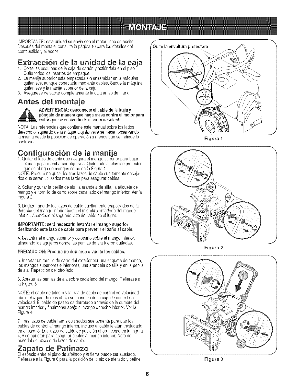
IMPORTANTE:esta unidadse env[acon el motorIlenode aceite,
Despu6sdel montaje,consultela pAg[na10paralos detallesdel
combustibley elace[te,
Extracci6n de la unidad de la cain
1, Corte lasesqu[nasde la caiade cart6ny ext[6ndalaen el p[so
Quitetodos los[nsertosdeempaque,
2, La manijasuperioresta empacadasin ensamNaren la m_quina
qu[tan[eve,aunqueconectadamed[antecanes, Saquela mAqu[na
quitanievey la maniiasuperiorde la cain,
3, AsegOresede vac[arcompletamentela ca]aantesde t[rarla,
Antes monta]e
ADVERTENClA:desconecteel cable de la buj[ay
p6ngalode maneraque haga masacontra el motor para
evitar quese eneiendade maneraaccidental.
NOTA:Las referenciasquecont[eneestemanualsobre loslados
derechoo [zquierdode lamb,quina quitanievese hacenobservando
la mismadesdela posici6nde operaci6na menosque se [ndiqueIo
contrario,
Configuraci6n de mamanija
1,Quitarel F_zode cane queasegurael mangosuperiorparabajar
el mangopara embarcarobjetivos,Quitetodo el plAst[coprotector
quese abr[gade mangoscomoen la Figura1,
NOTE:Procurenoqu[tarlostres lazosde cane sueltamenteenca]a-
dosque serAnut[l[zadosmAstarde paraasegurarcanes,
2, Soltary qu[tar la perillade ala, la arandelade silla, la et[quetade
mangoy el tornillode carrosobrecadalade del mangoinferior,Verla
Figura2,
3, Deslizaruno de los lazosde cane sueltamenteempotradosde la
derechadel mangoinferiorhastael miembroenfadadodelmango
inferior,Abandoneel segundolazode cane enel lugar,
IMPORTANTE:ser_ necesario levantar el mango superior
deslizando este lazo de cable para prevenir el daSoal cable.
4, Levantarel mangosuperiory colocarlosobreel mangoinferior,
al[neandolos agujerosdondelas per[llasde ala fueronqu[tadas,
PRECAUCION:Procure no doblarse o vuelta los cables.
5, Insertarun torn[llode carrodel exteriorpor unaetiquetade mango,
los mangossuperiorese [nferiores,unaarandeladesilla yen la perilla
deala, Repet[c[6ndel otro lado,
6, Apretarlasperillasde ala sobrecada ladedelmango,Refi6rasea
la Figura3,
NOTE:el camede taladroy laruta decane decontrolde velocidad
abajoel [zquierdomAsabajose manejande la caja de controlde
veloddad,Elcane depaseoes derrotadoa trav6sde lacumbredel
mangoinferiory finalmenteabajoel mangoderechoinferior,Verla
Figura4,
7,Treslazos de cane hans[do usadossueltamentepara atarlos
canes de controlal mangoinferior,[ndusoel cane le atantrasladado
enel paso3, Loslazosde cane depos[c[6nahora,comoenla F[gura
4, y se apr[etanparaasegurarcanes al mangoinferior,Netode
materialde excesode lazesde cane,
Zapato de Patinazo
Elespac[oentreel platode afe[tadoy la t[errapuede serajustado,
Refi6rasea la Figura6para laposici6ndelplatode afeitadoy paine
Qf_uitela envoltura protectora
\
\
\,
\
Fig_Jra 3
6
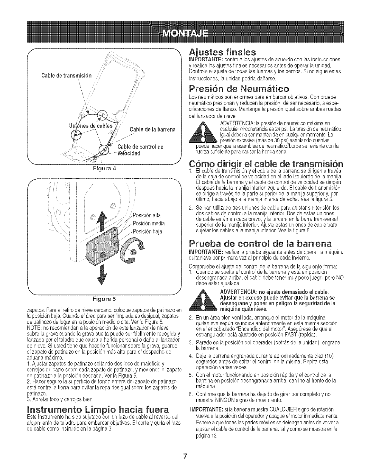
f
Cable de la barrena
f
Figura 4
J
iJ
,i f
ii i_ /
alta
, PosiciSnmedia
/ Posici6nbaia
Figura 5
zapatos.Parael retirede nievecercano,coloquezapatosde patinazoen
laposiciOnbaia.Cuandoel _reaparaser limpiadaesdesigual,zapatos
depatinazode lugarenlaposici6nmediao alta. Verla Figura5.
NOTE:no recomiendana la operaci6nde estelanzadorde nieve
sobrela gravacuandola gravasueltapuedeserfb,cilmenterecogiday
lanzadaper el taladroquecausaa heridapersonalo dahoal lanzador
de nieve.Si ustedtiene quehacerlofuncionarsobre la grava,guarde
elzapatode patinazoen la posici6nm_salta paraeldespachode
aduanam_ximo.
1.Aiustar zapatosde patinazosoltandodos Iocode maleficioy
cerrojosde carrosobrecadazapatode patinazo,y moviendoelzapato
de patinazoa laposici6ndeseada.Verla Figura5.
2. Hacersegurola superficiede fondoenteradel zapatodepatinazo
estb,contrala fierraparaevitarla ropadesigualsobrelos zapatosde
patinazo.
3. ApretarIocoy cerrojosbien.
Instrumento Limpio hacia fuera
Esteinstrumentohaside suietadocon un lazode cane al reversedel
alojamientode taladroparaembarcarobjetivos.El corte y quita el lazo
decane comeinstruidoenla p_gina3.
Aiustes finales
ORTANTE:controlelos ajustesde acuerdocon las instrucdones
y realicelosaiustesfinalesnecesariosantesdeoperarlaunidad.
Controleel aiustedetodaslas tuercasy los pernos.Si no sigueestas
instrucciones,la unidadpodriadaharse.
Presi6n de Neum tico
Losneum&ticosson enormesparaembarcarobjetivos.Compruebe
neum&ticopresionany reducenla presbn, de ser necesario,a espe-
cificacionesde fiance.Mantengalapresi6nigual sobreambasruedas
del lanzadorde nieve.
ADVERTENCIA:la presi6ndeneum_ticom_ximaen
cualquiercircunstanciaes24 psi.La presi6ndeneum_tico
igualdeberiasermantenidaen cualquiermemento.La
'm_sde30 asentandocuentas
_uuede ue se revientecon la
erzasufc enteparacausarla heridaseria.
C6mo dirigir el cable de transmisi6n
1. El cane de transmisi6ny el cane de la barrenase dirigena traves
de la cajade control de velocidaden el lade izquierdode la maniia.
Elcane de labarrenay el cablede control de velocidadse dirigen
des_,u6shaciala manilainferiorizquierda.El cablede transmisl6n
se dirigea travesde la parte superiorde la manijasuperiory,per
01time,haciaabaioala maniiainferiorderecha.Vea la figura5.
2. Sehartutilizadotres unionesde cane para ajustarsin tensi6nlos
dos canes de controla la maniiainferior.Dosde estasuniones
de cane est_nencadabraze,y la terceraen la barra transversal
superiorde la mania inferior.A uste estasunionesde cane para
suletar os cabes a a man a nferor.Vea a f gura 5.
Prueba de control de la barrena
IMPORTANTE:realicela pruebasiguienteantesde operarla m_quina
quitanieveperprimeravezal principiode cadainvierno.
Compruebeel ajustedelcontrolde labarrenade lasiguienteforma:
1. Cuandosesueltael controldela barrenay est_enposici6n
desengranadaarriba,el cane debetenermuy pocoiuego,peroNO
debeestaraiustada.
ADVERTENCIA:rio ajuste demasiado el cable.
Ajustar ene×ceso puede evitar que la barrenase
desengraney porter en peligro la seguridad de la
m_quina quitanieve.
2. Enunb,rea bien ventilada,arranqueel motorde la m&quina
quitanieveseg0nse indicaanteriormenteen esta mismasecci6n
en el encabezado"Encendidodel motor. Aseg0resede queel
estranguhdorest_ajustadoenposici6nFAST(rb,pida).
3. Paradeen laposici6ndeloperador(detr_sde launidad),engrane
labarrena.
4. Dee la barrenaengranadaduranteaproximadamentediez (10)
seguncIosantesdeso tar e centre de a m sma.Repta esta
operaclonvarlasveces.
5. Con el motorfuncionandoen posicbn r_piday el controlde la
barrenaen posici6ndesengranadaarriba,camineal frentede la
maquma.
6. Confirmeque la barrenaha dejadode girar per completey no
muestraNINGUNsignode movimiento.
IMPORTANTE:sila barrenamuestraCUALQUIERsignode retaci6n,
vuelvaa laposicbndeloperadory apagueelmotorinmediatamente.
Esperea quetodaslaspartesm6vilessedetenganantesde volvera
aiustarelcane decontroldelabarren&taly comese muestraenla
p_gina13.
7
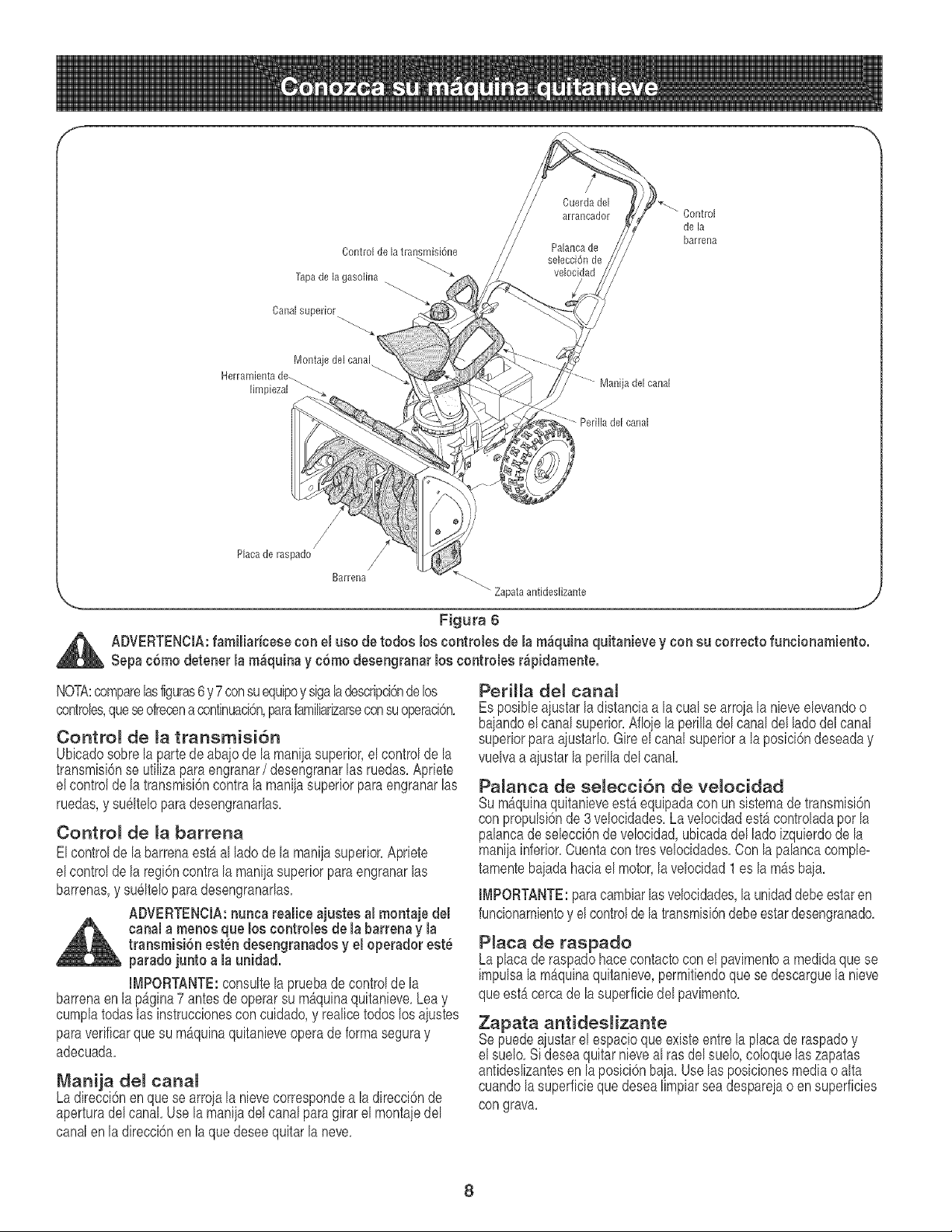
Control de la transmisi6ne
Tapade la gasolina
Canal superior..
Montaje del canal
Herramienta de.
limpiezal
....... Manija del canal
Perilla del canal
de la
barrena
,/
Placa de raspado
Barrena _.
" Zapata antideslizante
Figura 6
_ DVERTENCIA:familiariceee con el ueo de todoe los controlee de la m_quina quitanbve y con eu correeto funcionamiento.
Sepac6mo detener [a m_quinay c6mo deeengranar los contro[ee r_pidamente.
NOTA:comparelasfiguras6 y7consuequipoy sigaladescripcbndebs
controbs,queseofrecena continuad6n,parafamiliarizarseconsuoperad6n,
Control de la transmisi6n
Ubbado sobrela partede abajode la maniiasuperior,el controlde la
transmbi6nse utilizapara engranar/desengranarlas ruedas.Aprbte
elcontroldela transmisi6ncontrala maniiasuperiorparaengranarlas
ruedas,y su61teloparadesengranarlas.
Control de la barrena
Elcontrolde la barrenaestb,al lade de la maniiasuperior.Aprbte
elcontroldela regi6ncontrala maniiasuperiorpara engranarlas
barrenas,y su61teloparadesengranarlas.
ADVERTENCIA:nunca tea[ice ajuetee al montaje de[
canal a menoe que los controlee de la barrenay la
transmiei6n eeten deeengranadosy e[ operadoreet_
paradojunto a la unidad.
IMPORTANTE:consultela pruebade controlde la
barrenaenlapagina7antesdeoperarsu m_quinaquitanbve. Leay
cumplatodaslas instruccionescon cuidado,y realicetodos los ajustes
paraverificarque su m_quinaquitanbveopera de formaseguray
adecuada.
Manija del canal
Ladirecci6nenquese arrojala nbve correspondea ladirecci6nde
aperturadel canal. Use la maniiadel canalparagirarel montaiedel
canalen la direcci6nen la que @see quitarla neve.
Perilla del canal
Esposibleajustarladistaneiaa lacual se arroiala nbve elevandoo
bajandoel canalsuperior.Afloiela perilladelcanaldel lade del canal
superiorpara ajustarlo.Gire el canalsuperiora laposici6ndeseaday
vuelvaa aiustarlaperilladel canal
Pa[anea de se[ecci6n de velocidad
Sum_quinaquitanbve est_ equipadaconun sistemadetransmisi6n
con propulsi6nde 3 velocidades.La velocidadest_ controladapor la
palancade sebcci6n de velocidad,ubbada delladeizquierdode la
manijainferior.Cuentacon treevelocidades.Con lapalancacomple-
tamentebaiadahaciael motor,la velocidad1 es la m_s baia.
[MPORTANTE:paracambiarlasvelocidades,la unidaddebeestaren
funcionamientoy el controlde latransmisi6ndebeestardesengranado,
Plata de raspado
Laplacade raspadohacecontactocon el pavimentoa medidaquese
impulsala mSquinaquitanieve,permitbndoquese descarguela nbve
queest5cercade lasuperficiedel pavimento,
Zapata antideslizante
Sepuedeaiustarel espacioqueexisteentre la placade raspadoy
el suelo.Si deseaquitar nbve al ras del suelo,coloquelas zapatas
antideslizantesen la posici6nbaia. Use lasposbionesmediao alta
cuandola superficieque @sea limpiarsea despareiao ensuperficies
con grava,
8
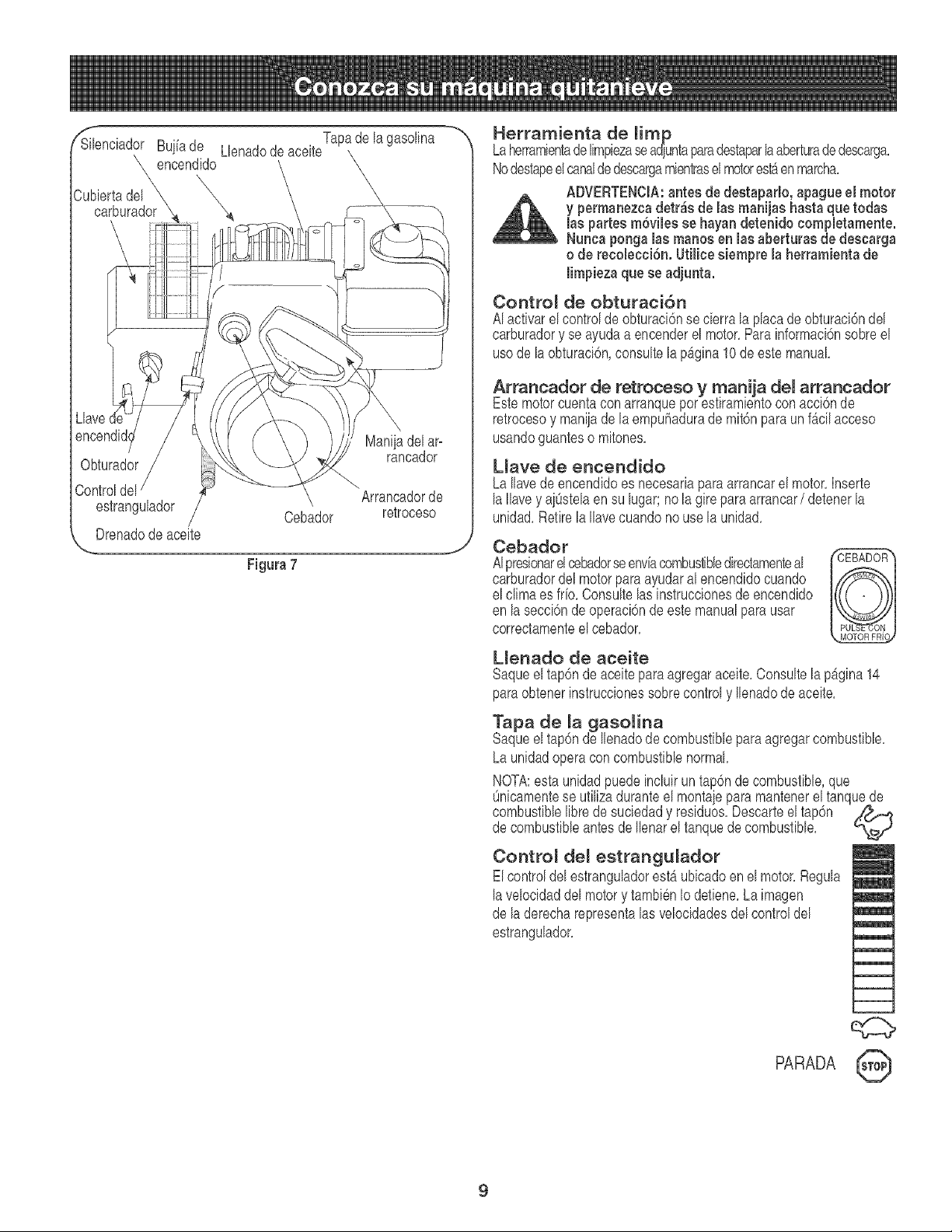
rSi_HenciadorBuj[ade Lbnadode aceiteTapade la gasolina
\ encendido X
Cubbrta del _,,
carburador
Llave
Obturador
Maniiadel ar-
rancador
Controldel \ Arrancadorde
estrangulador \,
/ Cebador retroceso
Drenadode aceite
Figura 7
J
Herramienta de mimp
Laherrambntadelimpbzaseadjuntaparadestaparlaaberturade descarga,
NodestapeeIcanaldedescargambntrasel motorestaen march&
ADVERTENCIA:antes de destaparlo, apague el motor
y permanezcadetr_s de las marqas hasta que todas
las partes m6viles se hayan detenido eompbtamente.
Nunea ponga las manosen las aberturas de descarga
o de reeobeci6n, Utiliee siempre la herramientade
limpieza que se adjunta.
Contro_ de obturaci6n
AI activarel controlde obturaci6nse cbrra la placadeobturaci6ndel
carburadory se ayudaa encenderel motor,Para informacbnsobreel
usode la obturaci6n,consultela pAgina10de estemanual
Arrancador de retroceso y manija del arrancador
Estemotorcuentacon arranquepor estirambntocon acci6nde
retroeesoy maniiade la empuhadurade mit6nparaunf_cilaeeeso
usandoguanteso mitones,
Llave de encendido
LaIlavedeencendidoes necesariapara arrancarel motor,Inserte
laIlavey aiOstelaen su lugar;no la gire paraarrancar/ detenerla
unidad,Retirela Ilaveeuandono usela unidad,
Cebador
AIpresionarelcebadorseenviacombustibbdirectamenteal
carburadordel motorpara ayudaral encendidocuando
el climaesfrio, Consultelas instruccionesde encendido
en lasecci6nde operaci6nde estemanualpara usar
correctamenteel cebador,
Llenado de aceite
Saqueeltap6nde aceitepara agregaraceite,Consultela p_gina 14
paraobtenerinstruccionessobrecontroly Ilenadode aceite,
Tapa de _a gasomina
Saqueeltap6nde Ilenadode combustibleparaagregarcombustible,
Launidadoperaconcombustibb normal,
NOTA:esta unidadpuedeincluiruntap6nde combustible,que
Onbamentese ufilizaduranteel montaiepara mantenerel tanquede
combustibblibredesucbdad y residuos,Descarteel tap6n _.f._
de combusfibbantesdeIlenarel tanquede combustible,
Contro_ de_ estrangu_ador
ElcontroldelestranguladorestAubbadoenel motor,Regula
lavelocidaddel motory tambi6nIo detbne, Laimagen
de laderecharepresentalasvelocidadesdel controldel
estrangulador,
m
q;z:>
PARADA 0
9
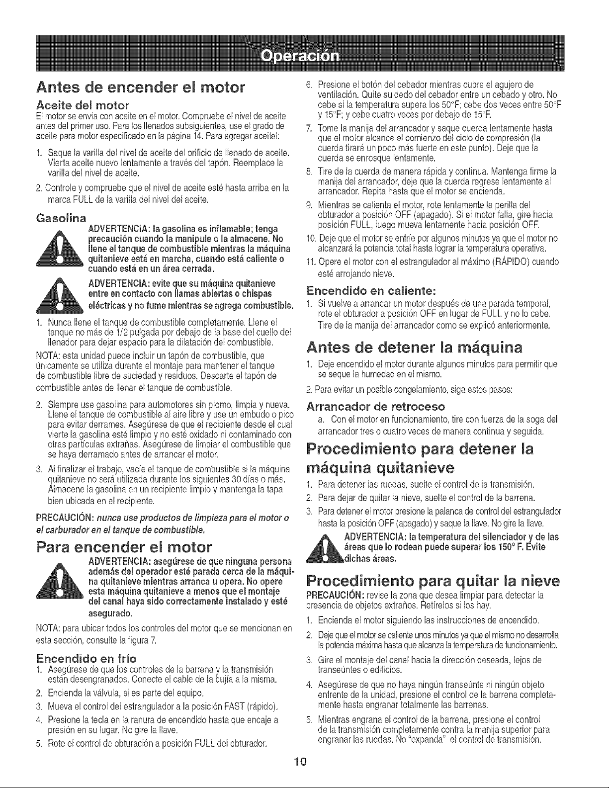
Antes de encender motor
Aceite del motor
Elmotorseenviaconaceiteen el motor,Compruebeel nivelde aceite
antesdelprimeruse,ParalosIlenadossubs[gu[entes,useel gradede
aceiteparamotorespecificadoenlap_gina14,Paraagregaraceitel:
1, Saquela var[lladel n[velde aceite del orificiode Ilenadode aceite,
V[ertaace[tonuevolentamentea trav6sdel tap6n,Reemplacela
varilladel nivelde aceite,
2, Controley compruebequeel n[veldeaceiteest6hastaarribaen la
marcaFULLde la varilladel niveldelaceite,
Gasolina
ADVERTENClA:la gasolina es inflamable;tonga
precauci6n cuando la manipule o la almacene. No
Ilene eltanque de combustible mientras la m_quina
quitanieve est_ en marcha,cuando est_ caliente o
cuando est_ en un _rea terraria.
ADVERTENCIA:evite que su m_quina quitanieve
entre encontaeto con llamasabiertae o chiegas
el_ctricae y no fume mientras eeagrega combustible.
1, NuncaIleneel tanquede combustiblecompletamente,Llene el
tanqueno m&sde 1/2 pulgadaper debajode la basedel cuellodel
Ilenadorparadeiar espac[opara la dilataci6ndel combustible,
NOTA:esta un[dadpuede[nclu[run tap6ndecombustible,que
_nicamentese ufil[zaduranteelmontajeparamantenereltanque
decombustiblelibredesuc[edady residues,Descarteel tap6nde
combustibleantesde Ilenarel tanquede combustible,
2, Siempreuse gasol[naparaautomotoressin plomo, I[mp[ay nueva,
Lleneel tanquede combustibleal aire librey use un embudoo pico
paraev[tarderrames,Aseg0resede que el recip[entedesdeel cual
viertelagasolinaeste limpioy no este oxidadon[ contaminadocon
otrasparticulasextrahas,Aseg0resede I[mp[arel combustibleque
se hayaderramadoantesde arrancarel motor,
3, AIfinal[zarel traba]o,vacieel tanquedecombustibles[la m&qu[na
quitanievenoser_ utilizadadurantelos siguientes30 dias o re&s,
AImacenela gasolinaenun recipientelimpioy mantengala tapa
bienubicadaen el recipiente,
PRECAUCION:nunca use preductos de Iimpieza para el meter e
el carburador en el tanque decombustible.
Para encender el motor
ADVERTENCIA:aseg_rese de que ninguna persona
_ dem_s del operador eet_ paradacerca de la m_qui-
na quitanieve mientrae arranca u opera. No opere
eeta m&quinaquitanieve a menos que el montaje
del canal hayaside correctamente instalado y eet_
asegurado.
NOTA:para ub[cartodos los controlesdel motorque se menc[onanen
estasecci6n,consultela figura7,
Encendido en fri'o
1, Aseg0resede que los controlesde la barrenay la transmisi6n
est_ndesengranados,Conecteel cablede labuiiaa la misma,
2, Enciendala v_lvula,s[es partedel equipo,
3, Muevael controldel estranguladora la posici6nFAST(rb,pido),
4, Presionela tecla en la ranurade encendidohastaqueencajea
presi6nen su lugar,No gire la Ilave,
5, Roteel controlde obturaci6na posici6nFULLdel obturador,
6, Pros[oneel bot6ndelcebadormientrascubreel aguierode
vent[lac[6n,Quitesu dedo del cebadorentre un cebadoy otro,No
cebe s[latemperaturasuperalos 50°F;cebedos vecesentre50°F
y 15°F;y cebe cuatrovecesperdebaiode 15°R
7, Tomela man[jadel arrancadory saquecuerdalentamentehasta
queel motoralcanceel comienzodel ciclo de compresi6n(la
cuerdat[rar_un pocomb,s fuerteen estepunto),Dejequela
cuerdase enrosquelentamente,
8, Tire de la cuerdademanerar&p[day continua.Mantengafirme la
manijadel arrancador,deieque la cuerdaregreselentamenteal
arrancador,Rep[tahastaque el motorse enc[enda,
9, M[entrasse cal[entael motor,rote lentamentelaper[lladel
obturadora posici6nOFF (apagado),S[el motorfalla,gire hacia
posici6nFULL,luego muevalentamentehaciaposici6nOFR
10,De]eque el motorse enfrieper algunosminutesyaque el motorno
alcanzar_lapotenciatotalhastaIograrla temperaturaoperat[va,
11,Opereel motorcon el estranguladoral m_x[mo(R,_RDO)cuando
estearroiandonieve,
Encendido en caHente:
1, s[ vuelvea arrancarun motordespuesde unaparadatemporal,
rote el obturadora posici6nOFFen lugarde FULLy no Iocebe,
Tire dela maniiadel arrancadorcomese explic6anteriormente,
Antes de detener la m quina
1, Dejeencendidoelmotordurantealgunosminutesparapermitirque
se sequela humedaden el mismo,
2, Paraevitarunposiblecongelamiento,sigaestospasos:
Arrancador de retroceso
a, Con el motorenfuncionamiento,tirecon fuerzade la sogadel
arrancadortres o cuatrovecesdemaneracontinuay seguida,
Procedimiento para detener
m quina quitanieve
1, Paradetenerlas ruedas,suelteel controlde la transm[si6n,
2, Para de]ardequ[tarla n[eve,suelteel control de la barrena.
3, Paradetenerel motorpros[onelapalancade controldel estrangulador
hastah posici6nOFF(apagado)y saquelaIhve,NogirelaIlave,
,_ADVERTENCIA: la temperatura del silenciador y de lae
_reas que Io rodean puedeeuperar los 1500F. Evite
dichae _reas.
Procedimiento para quitar la nieve
9RECAUClON:reviselazonaque desealimpiarpara detectarla
presenciade obietosextrahos,Refireloss[ los hay,
1, Enciendael motorsiguiendolas [nstrucc[onesdeencendido,
2, De]equeel motorsecalienteunosminutesyaqueelmismonodesarrolla
lapotenciam_ximahastaquealcanzalatemperaturadefuncionamiento,
3, Gire el montajedel canalhaciala direcci6ndeseada,leiosde
transe0nteso edificios,
4, Aseg0resede que no hayaning0ntranse0nten[n[ng0nobieto
enfrentede launidad,presioneel controlde labarrenacompleta-
montehastaengranartotalmentelas barrenas,
5, Mientrasengranael controlde la barrena,pros[oneel control
de latransmisi6ncompletamentecontra la manijasuperiorpara
engranarlas ruedas,No"expanda" el controlde transmisi6n,
10
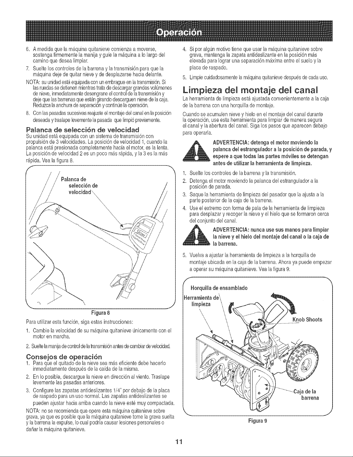
6. A medidaque lamb,quina quitanievecomienzaa moverse,
sostengafirmementela maniiay guie la m_quinaa Iolargodel
caminoquedesealimpiar.
7. Suelteloscontrolesde la barrenay la transm[s[6npara que la
m_quinadeje de quitar nievey de desplazarsehaciadelante.
NOTA:suunidadestaequipadaconunembragueen latransmisi6n.S[
lasruedassedetienenmientrastratadedescargargrandesvolOmenes
denieve,[nmediatamentedesengraneelcontroldelatransm[sbny
dejequehs barrenasqueestAng[randodescarguenn[evedelaca]a.
Reduzcala anchuradeseparaci6ny cont[nOelaoperad6n.
8. Conlaspasadassucesivasreaiusteel montaiedelcanalenh posicbn
deseaday traslapelevementelapasadaque limpi6previamente.
Palanca de selecci6n de velocidad
Suun[dadest_ equ[padaconun s[stemade transm[s[6ncon
propulsi6nde 3 velocidades.La posici6nde velocidad1,cuandola
palancaest_ pres[onadacompletamentehaciael motor,es la lenta.
Laposici6nde velocidad2 es unpoco mb,s r_pida,y la 3 es la m_s
r_pida.Veala figura8.
selecci6n de
velocidad_
\x
\
\
\
Figura 8
Paraufilizarestafunci6n,sigaestas [nstrucciones:
1. Cambiela velocidadde su m_quinaquitanieveOnicamenteconel
motoren march&
2. Sueltela maniadecontroldelatransmisi6nantesdecambiardeveloddad.
Conse]os de operaci6n
1. Paraque el quitadodela nieveseam_seficientedebe hacerlo
[nmed[atamentedespu6sdela caidade la m[sma.
2. En Io posible,descarguela nieveen direcci6nal viento.Traslape
levementelas pasadasanter[ores.
3. Configurelas zapatasantideslizantes1/4" pordebajode la placa
de raspadopara un uso normal Las zapatasantidesl[zantesse
puedenajustarhaciaarribacuandola nieveest6 muy compactada.
NOTA:no se recomiendaqueopereestam_quinaquitanievesobre
grava,ya quees pos[blequelam_qu[naqu[tan[evetomelagravasuelta
y labarrenalaexpulse,Iocualpodrfacausarlesionespersonaleso
daharlam_quinaquitanieve.
4. S[por algOnmot[vofieneque usarla m&quinaquitanievesobre
grava,mantengalazapataantideslizanteen laposici6nm4s
elevadapara Iograrunaseparaci6nm_ximaentreel suelo y la
placade raspado.
5. Limpiecuidadosamenteh m4quinaquitanievedespu6sdecadauso.
Limpieza deJ monta]e del canal
Laherramientade limpiezaest&aiustadaconvenientementea la caja
de labarrenacon unahorquillade monta]e.
Cuandose acumulennievey hieloen el montajedel canaldurante
laoperaci6n,useesta herramientapara limpiarde manerasegura
el canaly la aberturadel canal Sigalos pasosque aparecendebajo
paraoperarla.
ADVERTENClA:detenga el motor moviendo la
palancadel estrangulador a la posici6nde parada,y
espere a que todas las partes m6viles se detengan
antes de utilizar la herramienta de limpieza.
1. Sueltelos controlesde la barrenay la transm[si6n.
2. Detengael motormoviendolapalancadel estranguladora la
posici6nde parada.
3. Saquela herram[entade I[mp[ezadelpasadorque la a]ustaa la
parteposteriorde la caia de la barren&
4. Useel extremocon formade pala de la herram[entade I[mp[eza
paradesplazary recogerla nievey el hieloquese formaroncerca
del conjuntodel canal.
ADVERTENClA:nunca use sue manos para limpiar
la nieve y el hielo del montajedel canal o la caja de
la barrena.
5. Vuelvaa ajustar la herramientade limpiezaa la horquillade
montaieubicadaen la cajade labarrena.Ahorayapuede empezar
a operarsu maquinaquitanieve.Vealafigura9.
Figura 9
11
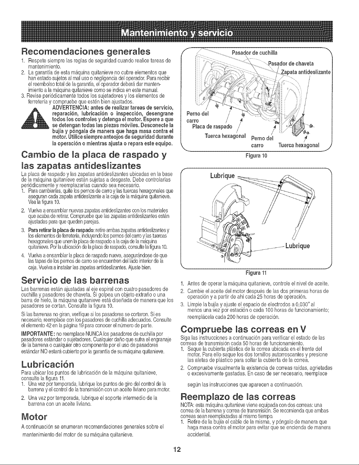
Recomendaciones generales
1, Respetesbmpre las reglasde seguridadcuandorealicetareasde
mantenimiento,
2, La garantiadeestamaquinaquitanbve no cubreebmentos que
hanestadosuietosal realusoo negligeneiadeloperador,Pararecibir
elreembolsototaldelagarantfa,el operadordeber_darmanten=
imbntoa lam_quinaquitanievecomose indieaen estemanuak
3, Reviseperi6dieamentetodos los suietadoresy los ebmentosde
ferreter[ay compruebeque esten bien aiustados,
ADVERTENCIA:antes de realizartareas de servbio,
reparaci6n, lubrbaci6n o inspecci6n, desengrane
todos los eontrobs y detenga el motor. Espere a que
se detengan todas las piezasm@ibs. Desconecte la
bqia y p6ngalade manera que haga masaeontra el
motor. Utilice siempre anteojos de seguridad durante
la operacien o mientras ajusta o repara esteequipo.
Cambio de p aca de raspado y
las zapatas antideslizantes
Laplacade raspadoy laszapatasantideslizantesubicadasen labase
dela mAquinaquitanieveestAnsu etas a desgaste,Debecontrolarlas
peri6dicamentey reemplazarlascuandosea necesario,
1, Paraeambiarlas,quitelosjoernosdecarroy lastuereashexagonabsque
asegurancadazapataantldeslizantea la caiade la m_quinaquitanieve,
Vealafigura10,
2, Vuelvaaensamblarnuevaszapatasantideslizantesconlosmateriabs
queacabade retirar,Compruebequelaszapatasantideslizantesest_n
aiustadasparaquequedenpareias,
3, Pararetirarlaplacaderaspado:retireambaszapatasantideslizantesy
loselementosdeferreteria,incluyendolospernosdelcarroylastuercas
hexagonabsqueunenlaphcade raspadoa lacaadelam_quina
quitanbve,Perlaubicaci6nde laplacaderaspado,consultelafigura10,
4, Vuelvaaensamblarlaplacade raspadonueva,asegur_.ndosede que
lastapasde lospernosde carroseencuentrendel ladeinteriordela
caja,Vuelvaa instalarlaszapatasantideslizantes,Ajustebien,
Servicio de barrenas
Las barrenasestAnaiustadasal eie espiralcon cuatropasadoresde
cuchillay pasadoresdechaveta,Sig@ea unobietoextrahoo una
barrade hielo,la m_quinaquitanieveestb,disehadade maneraque los
pasadoresse cortan,Consultela figura10,
Silasbarrenasnogiran,verifiquesi lospasadoresse cortaron,Sies
necesario,reemplaceconlospasadoresde euchillaadecuados,Consulte
elebmento42enlap_gina19paraconocerel nOmerode parte,
I[_IPORTANTE:noreemplaeeNUNCAlospasadoresdecuehillapor
pasadoresest_ndaro suietadores,Cualquierdahoquesufrael engranaie
delabarrenaoeualqubrotroeomponenteporel usodepasadores
est_ndarNOestar_eubiertoporla garantiadesum_quinaquitanieve,
Lubricaci6n
Paraubicarlos puntosde lubricaci6nde la mAquinaquitanieve,
consultela figura11,
1, Unavezper temporada,lubriquelospuntosde giro delcontrolde la
barrenay elcontrolde latransmisi6nconunaceitelivianoparamotor,
2, Unavezportemporada,lubriqueel soporteintermediode la
barrenacon unaceiteliviano,
Motor
A confinuaci6nseenumeranrecomendacionesgeneralessobreel
mantenimientodel motorde su m_quinaquitanieve,
Pernodel
earro / S
Placade raspado _-
Tuercahexagonal Pernodel
carro Tuercahexagonal
Figura 10
Lubrique
;_ue
Figura 11
1, Antesdeoperarlam_quinaquitanbve,controb el nivelde aceite,
2, Cambb el aceitedel motordespuesde las dosprimerashorasde
operaci6ny a partir de ah[ cada25 horasde operaci6n,
3, Limpb la bu iay a usteel espaciode electrodesa 0,030"al
menosunavezperestaci6no cada 100 horasdefuncionambnto;
reempl9celacada200 horasde operaci6n,
Compruebe correas en
V
Sigalas instruccionesa continuaci6nparaverificarel estadode las
correasde transmbi6ncada 50 horasdefuncionambnto,
1, Saquelacubbrta plAstbade lacorreaubbada en el frentedel
motor,Paraello saquelos dostornillosautorroscantesy presione
las abtas deplAstboparasoltarlacubbrta dela correa,
2, Compruebevisualmentela existenciade correas raidas,agrbtadas
o excesivamentegastadas,Encasede ser necesario,reemplace
segOnlas instruccionesqueaparecena continuaci6n,
Reemp azo de correas
NOTA:estam_quinaquitanbvevieneequipadacondoscorreas:una
correade la barrenay correadetransmisi6n,Se reeomiendaqueambas
correasseanreemplazadasal mismotiempo,
1, Retirede la buliaelcabb dela misma,y p6ngalode maneraque
hagamasacontrael motorparaevitarquese enciendade manera
accidental
12
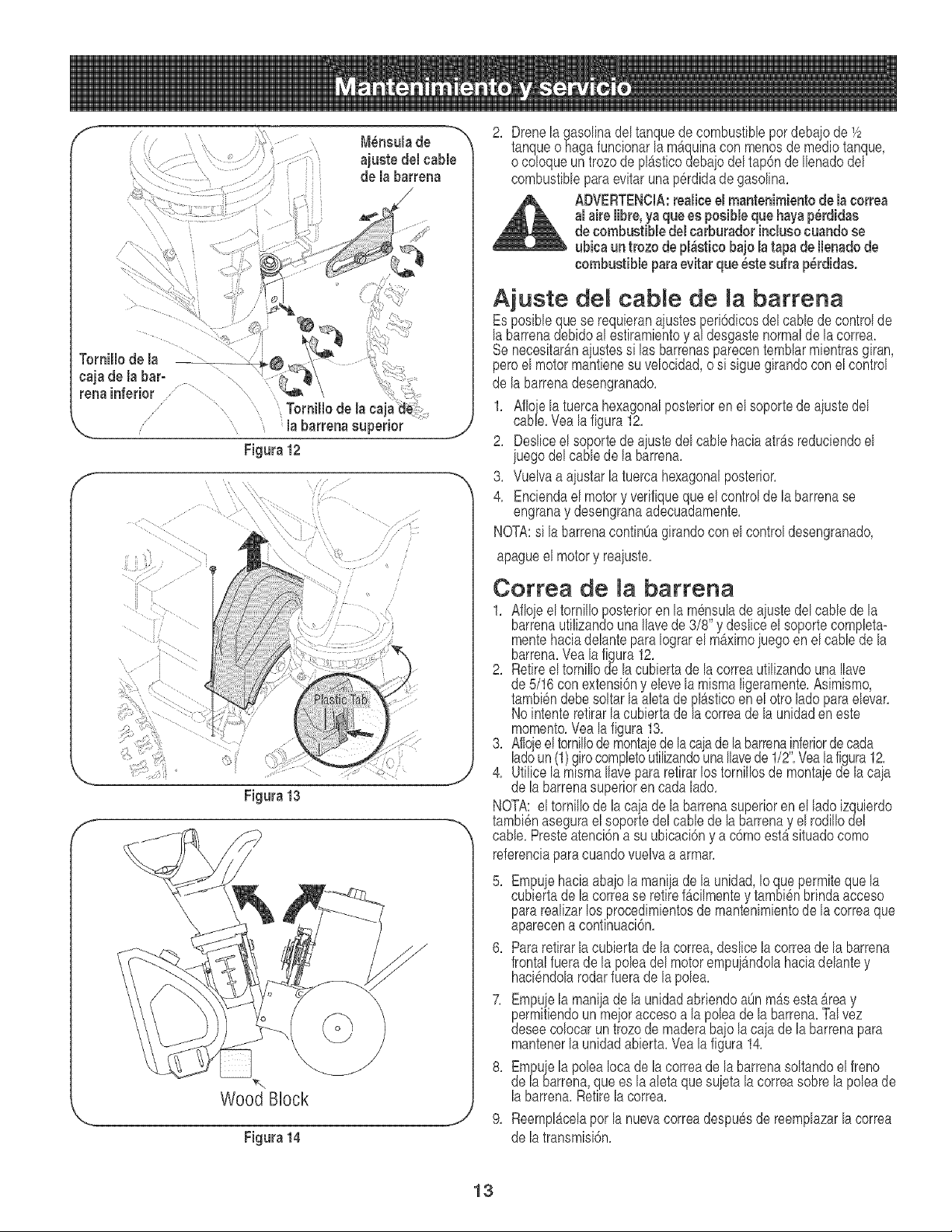
f
n
Mensulade "_
ajuste del cable
de la bacteria
/
f
Figuca12
f
Figuca13
J
\
Wood BHock
J
Figura 14
2. Drenela gasolinadel tanquedecombustiblepordebajode 1/2
tanqueohaga funcionarla m&quinacon menosde mediotanque,
o coloqueun trozode pl_sficodebaiodel tap6nde Ilenadodel
combustibleparaevitarunap6rdidade gasolina.
ADVERTENCIA:cealiceel mantenimientode la coccea
al aicelibre, yaque eeposibleque hayap_rdidae
de combustibledel carburadorinclueocuando se
ubicaun trozo de pl_etico bajo la tapa de Ilenadode
combustible paraevitacque _eteedra p_rdidae.
Aiuste del cable de Ja barrena
Esposiblequese requierana ustesperi6dicosdel cablede controlde
labarrenadebidoal estiramientoy a/desgastenormalde la correa.
Senecesitarb,n a ustessi las barrenasparecentemblarmientrasgiran,
peroe motormantenesu ve oc dad,o s s gue girandocon el control
de labarrenadesengranado.
1. Afioe la tuercahexagonalposterioren el soportedeaiustedel
cabe. Vea a f gura 12.
2. Desliceel soportede a uste del cable haciaatr_,sreduciendoel
iuegodel cablede la barrena.
3. Vuelvaa aiustarla tuercahexagonalposterior.
4. Enciendael motory verifiqueque el controlde la barrenase
engranay desengranaadecuadamente.
NOTA:sila barrenacontinOagirandoconel controldesengranado,
apagueel motory reaiuste.
Correa de Rabarrena
1. Afloe el tornilloposterioren la mensuladea ustedel cablede la
barrenautilizandounaIlavede 3/8' y desliceel soportecompleta-
mentehaciadelanteparaIograrel m_ximoiuegoenel cablede la
barrena.Vea la figura12.
2. Retireeltornillode la cubiertade la correaufilizandounaIlave
de 5/16con extensi6ny elevela mismaligeramente.Asimismo,
tambi6ndebesoltarlaaletade pl_sficoen el otroladeparaelevar.
Nointenteretirarlacubiertadeh correade la unidaden este
memento.Vealafigura 13.
3. Aflojeel tornillodemontaiedelacaiade la barrena,!nferiordecada
ladeun(1)girocompletoutilizandounaIlavede 1/2. Veala figura12.
4. Utilicela mlsmaIlavepararetirarlos tornillosde montaiede lacaia
de la barrenasuperioren cadalade.
NOTA:el tornillode lacaja dela barrenasuperioren el lade izquierdo
tambi6nasegurael soportedel cable de la barrenay el rodillodel
cable.Presteatenci6na su ubicaci6ny a c6moest_situadocome
referenciaparacuandovuelvaa armar.
5. Empuiehaciaabajola manijade la unidad,Io quepermitequela
cubiertade la correase retiref4cilmentey tambi6nbrindaacceso
pararealizarlos procedimientosde mantenimientode la correaque
aparecena confinuaci6n.
6. Pararetirarla cubiertade la correa,deslicela correade la barrena
frontalfuerade la poleadel motorempui_ndolahaciadelantey
haci6ndolarodarfuerade la polea.
7. Empue la mania de la unidadabriendoaOnmb,s esta_rea y
permitiendoun meieraccesoa la poleade labarrena.Talvez
deseecolocar un trozode maderabaio la caia de la barrenapara
mantenerlaunidadabierta.Veala figura14.
8. Empuiela polea Iocade la correade labarrenasoltandoelfreno
de h barrena,que es la aleta quesu eta la correasobrela poleade
labarrena.Retire la correa.
9. ReemplAcelaper la nuevacorreadespu6sdereemplazarla correa
de la transmisi6n.
13
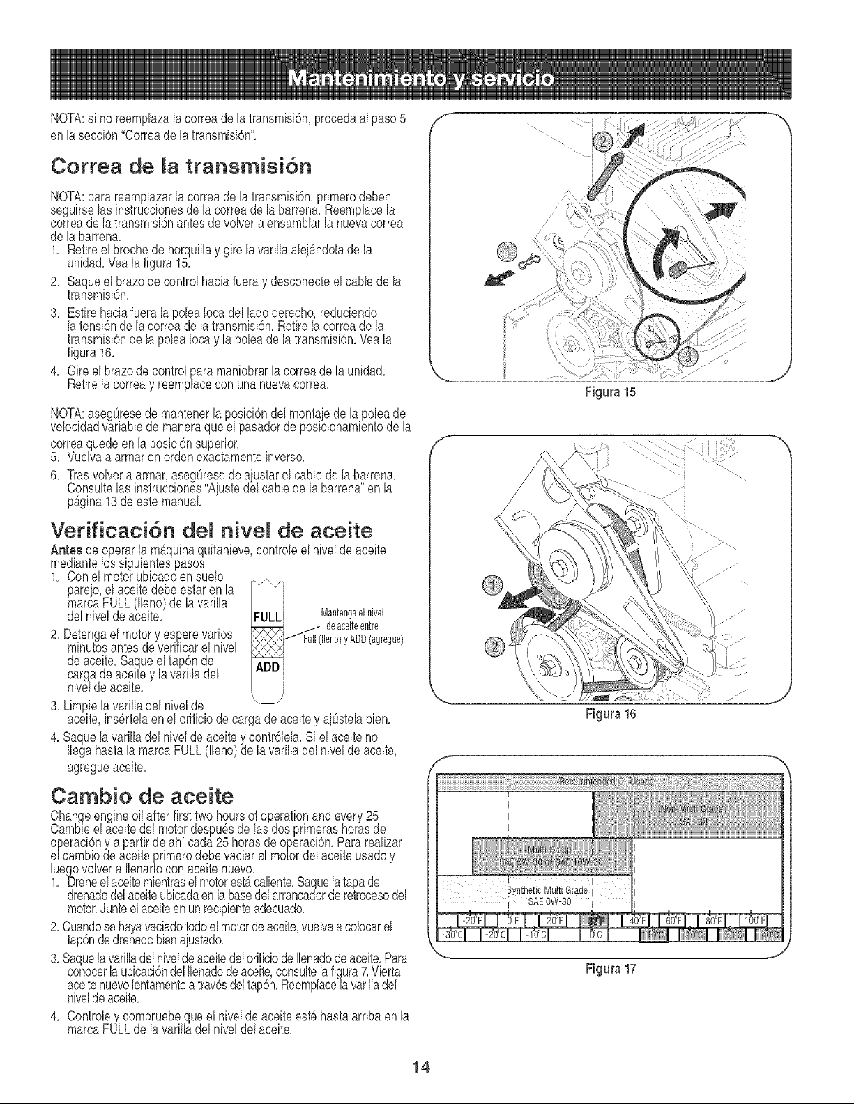
NOTA:si no reemplazala correadela transmisi6n,procedaal paso5
en lasecci6n"Correade la transmisi6n".
Correa de la transmisi6n
NOTA:para reemplazarla correadela transmisi6n,primerodeben
seguirselasinstruccionesde lacorreade la barren& Reemplacela
correade la transmisi6nantesde volvera ensamblarla nuevacorrea
de labarrena.
1. Retireel brochede horquillay gire la varillaaleiAndolade la
unidad.Vea la figura 15.
2. Saqueel brazode controlhaciafueray desconecteel cane de la
transmisi6n.
3. Esfire haciafuera la polea Iocadel ladoderecho,redudendo
la tensi6nde lacorreade la transmisi6n.Retirelacorreade la
transmisi6ndela poleaIocay la poleade la transmisbn.Veala
figura16.
4. Gire el brazode controlpara maniobrarla correade la unidad.
Retirela correay reemphce con una nuevacorrea.
NOTA:asegOresede mantenerla posici6ndel montae de la poleade
velocidadvariablede maneraque el pasadorde posicionamientode la
correaquede en la posici6nsuperior.
5. Vuelvaa armaren ordenexactamenteinverso.
6. Trasvolvera armar,asegOresede a ustarel cablede lab,arrena.
Consultelas instrucciones"Aiustedelcane de la barrena en la
p_gina13deeste manual
Verificaci6n del nivel de aceite
Antes de operarla mbquinaquitanieve,controleel nivelde aceite
mediantelos siguientespasos
1. Conel motorubicadoen suelo
pareio,el aceitedebe estar en la
marcaFULL(lleno)de lavarilla
delnivelde aceite. FULLi Mantengaelnivel
RF:2qR_ deaceiteentre
2. Detengael motory esperevarios _f Full(lleno)yADD(agregue)
minutesantesde verificarel nivel
deaceite.Saqueel tap6n de ADD
cargade aceite y la varilladel
nivelde aceite.
3. Limpiela varilladel nivelde
aceite,ins6rtelaen el orificiode cargade aceitey aiOstelabien.
4. Saquela varilladel nivelde aceitey contr61ela.Si el aceite no
Ilegahasta la marcaFULL (lleno)de la varilh del niveldeaceite,
agregueaceite.
Cambio de aceite
Changeengineoil after firsttwo hoursof operationandevery25
Cambieelaceitedel motordespuesde lasdos primerashorasde
operaci6ny a partirdeah[ cada25 horasdeoperaci6n.Pararealizar
elcambio deaceiteprimerodebe vaciar el motordel aceiteusadoy
luegovolvera Ilenarlocon aceitenuevo.
1. Dreneelaceitemientrasel motorest_caliente.Saquelatapade
drenadodelaceiteubicadaen la basedel arrancadorderetrocesodel
motor.Junteel aceiteen un recipienteadecuado.
2.Cuandose hayavaciadotodoel motorde aceite,vuelvaacolocarel
tap6ndedrenadobienaiustado.
3. Saquelavarilladel nivelde aceitedelorificiode Ilenadodeaoeite.Para
conocerlaubicaci6ndelIlenadodeaceite,consultela figura7.Vierta
aceitenuevolentamenteatrav6sdeltap6n.Reemplacela varilladel
nivelde aceite.
4. Controley compruebeque el nivelde aceiteest6hastaarribaen la
marcaFULLde la varilladel niveldelaceite.
14
f
f
Figura 15
Figura 17
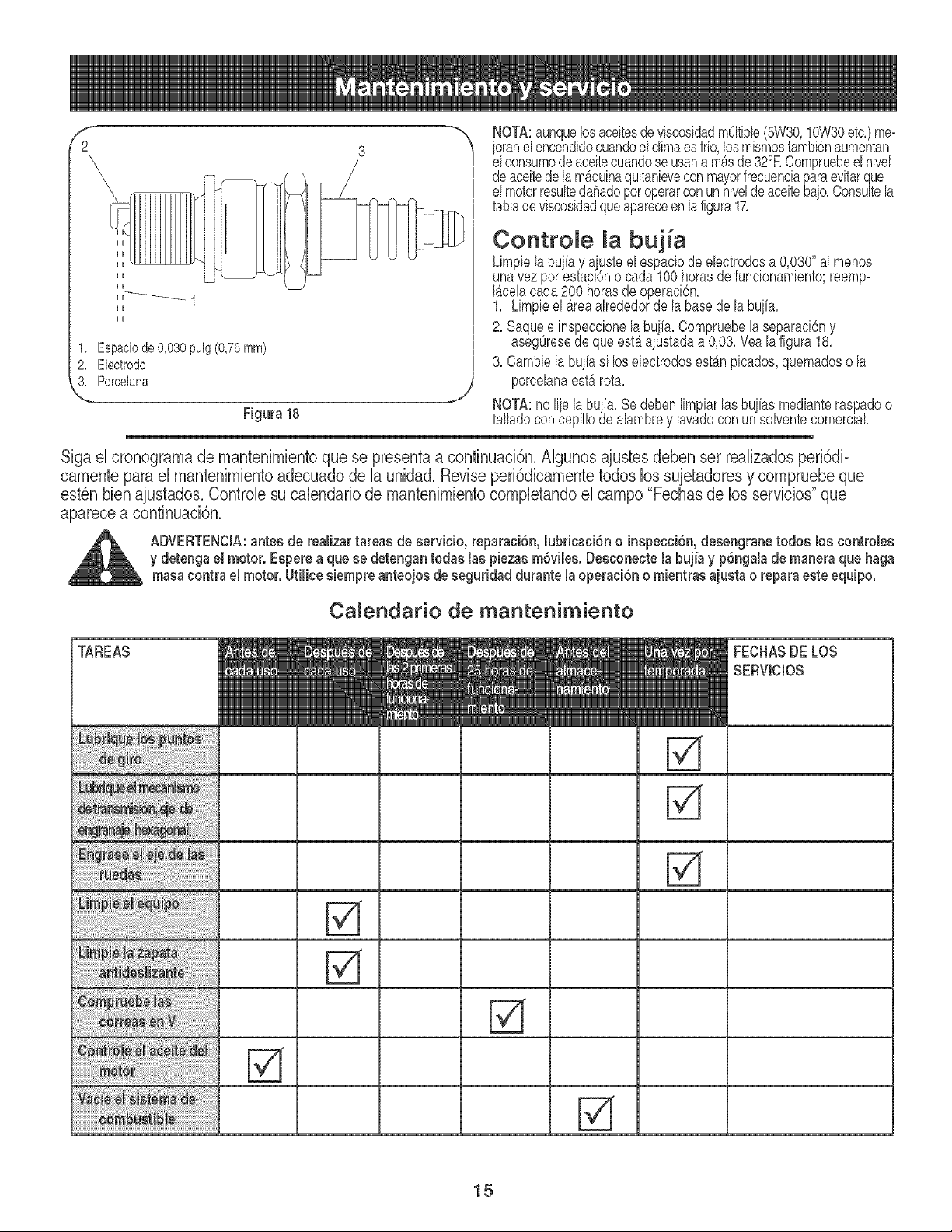
f
2
1, Espaciode 0,030 pulg (0,76ram)
2. Electrodo
L Porcelana
NOTA:aunquelosaceitesde viscosidadmOltiple(5W30,10W30etc.)me=
oranelencendidocuandoel climaes frfo,losmismostambienaumentan
e consumode acetecuandoseusana m&sde32°RCompruebee nve
deaceitedelam&quinaquitanieveconmayorfrecuenciaparaevitarque
el motorresultedahadoporoperarconun niveldeaceitebaio.Consultela
tablade viscosidadqueapareceenlafigura17.
Contro e bujia
Limpiela bui[ay ajusteel espaciodeelectrodosa 0,030"al menos
unavezpor estac_6no cada100horasde funcionamientcreemp=
I_celacada200 horasdeoperaci6n.
1. Limpieel _reaalrededorde la basede labuiia.
2. Saquee inspeccionela bujia. Compruebela separaciony
asegOresede queest_aiustadaa 0,03.Veala figura18.
3. Cambielabuiiasi los electrodosest_n picados,quemadoso la
porcelanaest_ rota.
"Y NOTA:no li e la bu ia. Se deben limpiarlas bu ias medianteraspadoo
Figura 18 talladocon cep o deaambrey avadocon unsovente comerc_a.
Siga el cronograma de mantenimientoque se presentaa continuaci6n, AIgunos ajustes deben ser realizados peri6di=
camente para el mantenimientoadecuado de la unidad, Revise peri6dicamente todos los sujetadores y compruebe que
est6n bienajustados, Controle su calendario de mantenimiento completandoel campo "Fechas de los servicios" que
aparece a continuaci6n,
ADVERTENCIA:antes de realizar tareas de servicio, reparaci6n, lubricaci6n o inepecci6n, deeengrane todoe los controlee
y detenga el motor. Eeperea queee detengantodae las piezasm6viles.Deeconectela bujia y p6ngalade maneraque haga
maeacontra el motor. Utilice siempre anteojos de seguridad durante la operaci6n o mientrae ajusta o repara este equipo.
Camendario de mantenimiento
1
1
1 1 1
1
Fa
Fa
Fa
FECHASDELOS
SERVICIOS
15
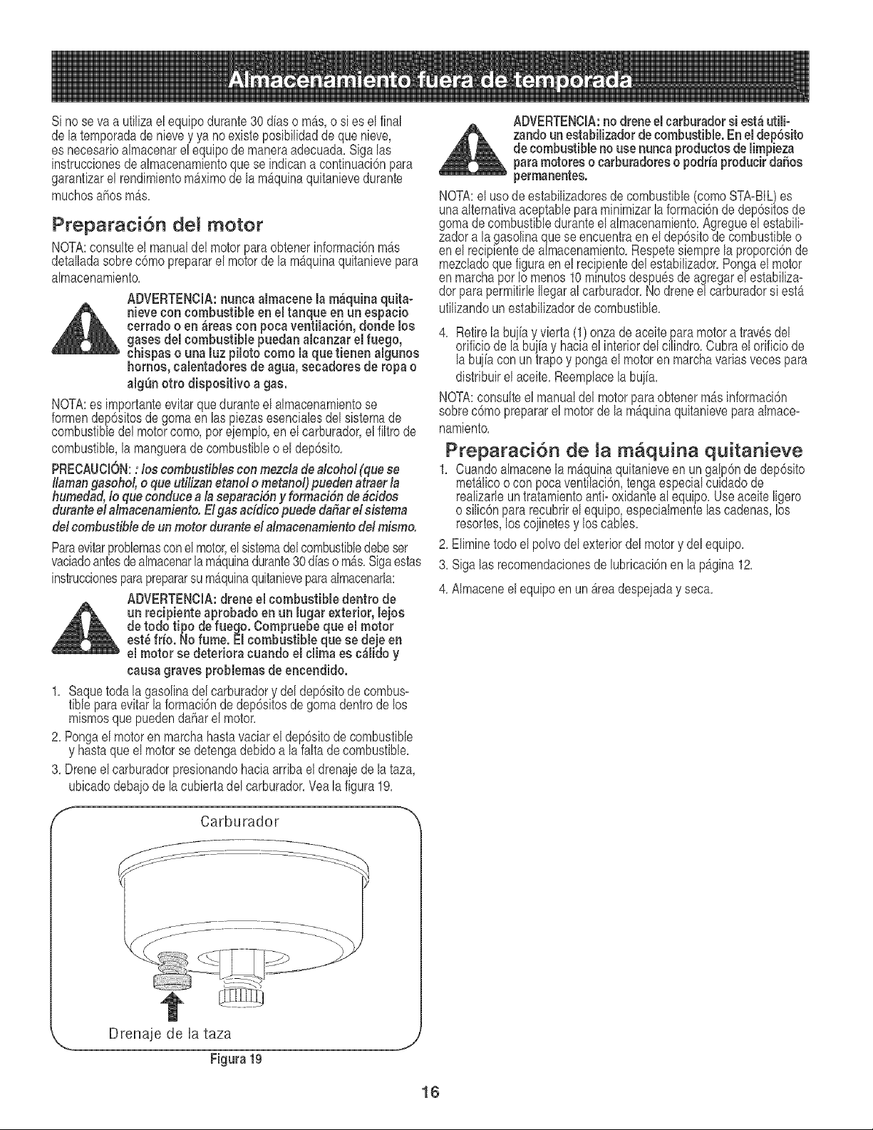
Si nose va a utilizael equipodurante30 diaso mb_s,o si es el final
de latemporadade nievey ya no existeposibilidadde que nieve,
es necesarioalmacenarel equipodemaneraadecuada.Siga las
instruccionesde almacenamientoque se indicana confinuaci6npara
garanfizarel rendimientom_ximode la m_,quinaquitanievedurante
muchosahos mAs.
Preparaci6n de! motor
NQTA:consulteel manualdel motorparaobtenerinformaci6nmb,s
detalladasobrec6moprepararel motordela mAquinaquitanievepara
almacenamiento.
ADVERTENCIA:nunca almacene la m_quina quita-
_lj ieve con combustible en el tanque en un espacio
cerrado o en _reas con pocaventilaciSn, deride los
gases del combustible puedan alcanzar el fuego,
chispas o una luz piloto come la que tienen algunos
homes, calentadores de agua, secadores de ropa o
alg_n otto dispositivo a gas.
NOTA:es importanteevitarqueduranteel almacenamientose
formendep6sitosde gomaen laspiezasesencialesdel sistemade
combustibledel motorcome,per eiemplo,en el carburador,el filtro de
combustible,la mangueradecombustibleo el dep6sito.
PRECAUCION:: los combustiblescon mezda dea/cehd (que se
Hamangasehd, e que utilizanetanefe metand) puedenatraer/a
humedad,/e queconducea/a separaeidny fermaddn de brides
duranteel afmaeenamiente.EIgas addiee puede dafiar el sistema
de/combustible deun meter duranted almacenamientedd misme,
Paraevitarproblemasconel motor,elsistemadelcombustibledebeser
vaciadoantesdealmacenarlamb,quinadurante30 d[aso mb,s. Sigaestas
instruccionesparaprepararsu m_quinaquitanieveparaalmacenarla:
ADVERTENCIA:drone el combustible dentro de
un recipiente aprobado en un lugar exterior, lejos
de todo tipo de fuego. Compruebe que el motor
est_frio. No fume. El combustible que se deje en
el motor se deteriora cuando el clima es c_lido y
causagraves problemasde encendido.
1. Saquetoda la gasolinadel carburadory del dep6sitode combus=
fiblepara evitar la formaci6nde dep6sitosde gomadentrode los
mismosque puedendaF_arel motor.
2. Pongael motoren marchahastavaciarel dep6sitode combustible
y hastaqueel motorse detengadebidoa la falta de combustible.
3. Droneel carburadorpresionandohaciaarribael drenajedela taza,
ubicadodebaiode la cubiertadel carburador.Vea la figura 19.
_" Carburador '_
ADVERTENCIA:no drone el carburadorsi est_utilio
zandoun estabilizadordecombustible. Enel dep6sito
decombustibleno use nuncaproductos de limpieza
paramotoreso carburadoreso podria producir daSos
permanentes.
NOTA:el usede estabilizadoresde combustible(comeSTA-BIL)es
unaalternativaaceptablepara minimizarla formaci6nde dep6sitosde
gomade combustibleduranteelalmacenamiento.Agregueel estabili=
zadora la gasolinaque se encuentraen el dep6sitodecombustibleo
en el recipientedealmacenamiento.Respetesiemprela proporci6nde
mezcladoque figuraenel recipientedelestabilizador.Pongael motor
en marchaperIo menos10minutesdespuesde agregare_estabiliza-
dor parapermitirleIlegaral carburador.Nodreneel carburadorsi est_
ufilizandounestabilizadorde combustible.
4. Retire la bu iay vierta (1)onza de aceite paramotora travesdel
orf c o de a buiay hacae nteror de c lindro.Cubrae or f c o de
la bujiacon untrapoy pongael motoren marchavariasveces para
distribuirel aceite.Reemplacelabujia.
NOTA:consulteel manualdel motorpara obtenerm&sinformaci6n
sobrec6mo prepararel motorde la m_quinaquitanieveparaalmace=
namiento.
Preparaci6n de la m quina quitanieve
1. Cuandoalmacenelamb,quinaquitanieveen un galp6nde dep6sito
moth,lice o con pocaventilaci6n,tongaespecialcuidadode
realizarleun tratamientoanti- oxidanteal equipo.Use aceite ligero
o silic6npararecubrirel equipo,especialmentelascadenas,los
resortes,los coiinetesy los cables.
2. Eliminetodoel polvodel exteriordel motory del equipo.
3. Sigalas recomendacionesde lubricaci6nenla pb,gina 12.
4. Almaceneel equipoen unb,rea despejaday seca.
Drenaje de [a taza
Figura 19
16
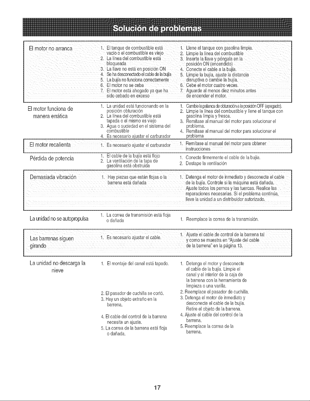
7. ElmotorestSahogadoyaqueha 7: Aguardealmenosdiezminutosantes
sido cebadoen exceso de encenderel motor.
El motor funciona de
1. La unidadestb,funcionandoen la
posici6nobturaci6n
2. Lalineadelcombustibleest_
tapadao el mismoes vie]o
3. Agua o suciedaden el sistemadel
combustible
4. Esnecesarioa[ustarelcarburador
1. Cambielapalancadeobturacbna h posici6nOFF(apagado).
2. Limpiela linea del combustibley Ileneeltanquecon
gasolinalimpiay fresca.
3. Remitaseal manualdel motor parasolucionarel
problema.
4. Rem[taseal manualdel motor parasolucionarel
problema
1. El cablede labui[aestb,floio 1. Conectefirmementeel cablede labuiia.
P6rdida de potencia 2. Laventilaci6nde la tapa de
gasolinaest5 obstruida 2. Destapela ventilaci6n
Demasiada vibraci6n i, Haypiezasqueestanfiojase la !. Detengael motorde inmediatoy desconecteelCable
barrenaest_da_ada de [a bujia.Controlesi la rnaquinaesta ddiada.
Ajustetodos lospemosy las tuercas.Realicelas
reparacionesnecesarias.Si el problemaContin8a,
Ilevelaunidada un distribuidorautorizado.
Launidadnoseautopropulsa
1. La correade transmisi6nest_floia
o daF_ada
1. Reemplacelacorreade la transmisi6n.
La unidad no descarga la
nieve
1. El montaiedel canalestb.tapado.
2. El pasadorde cuchillase cort6.
3. Hayun obietoextrahoen la
barrena.
4. El cabledel controlde la barrena
necesitaun aiuste.
5. La correade la barrenaest_ floia
o dahada.
1. Detengael motory desconecte
el cablede la buiia.Limpieel
canaly el interiorde la caia de
labarrenacon laherramientade
limpiezao unavarilla.
2. Reemplaceel pasadordecuchilla.
3. Detengael motorde inmediatoy
desconecteel cablede la bujfa.
Retireel obietode la barrena.
4. Aiusteelcable delcontrolde la
barrena.
5. Reemplacela correade la
barrena.
17

iiiiiiiiiiiiiiiiiiiiiiiiii?ii_....
iiiiiiiiiiiiii_,_,'
iiiiiiiiiiiiii
iiiiiiiiiiiiii
iiiiiiiiiiiiii
iiiiiiiiiiiiii
iiiiiiiiiiiiii
iiiiiiiiiiiiii
iiiiiiiiiiiiii
iiiiiiiiiiiiii
iiiiiiiiiiiiii
iiiiiiiiiiiiii
iiiiiiiiiiiiii
iiiiiiiiiiiiii
iiiiiiiiiiiiii
iiiiiiiiiiiiii
iiiiiiiiiiiiii
iiiiiiiiiiiiii
iiiiiiiiiiiiii
iiiiiiiiiiiiii
iiiiiiiiiiiiii
iiiiiiiiiiiiii
iiiiiiiiiiiiii
iiiiiiiiiiiiii
iiiiiiiiiiiiii
iiiiiiiiiiiiii
iiiiiiiiiiiiii
iiiiiiiiiiiiii
iiiiiiiiiiiiii
iiiiiiiiiiiiii
!_i_!jjjjjjjjjjjjjji_i_i
Your Home
For repair-in your home-of all major brand appliances,
lawn and garden equipment, or heating and cooling systems,
nomatterwhomade.. nomatterwho o,dit,
iiiiiiiiiiiiiiiiii
For the replacement parts, accessories and
owner's manuals that you need to do-it-yourself.
iiiiiiiiiiiiiHHi
For Sears professional installation of home appliances
and items like garage door openers and water heaters.
1-800-4-MY-HOME ® (1-800-469-4663)
Call anytime, day or night (U.S.A. and Canada)
www.sears.cor,www.sear .ca
OurHome
For repair of carry-in items like vacuums, lawn equipment,
and electronics, call or go on-line for the location of your nearest
Sears Parts & Repair Center.
1-800-488-1222
Call anytime, day or night (U.S.A. only)
www.sears.corn
To purchase a protection agreement (U.S.A.)
or maintenance agreement (Canada)on i product serviced by Sears:
1 800 827 6655 (U.S.A.) 1 800 361 6665 (Canada)
Pare pedir servicio de reparaciOn Au Canada pour service en frangais:
a domicilio, y para ordenar piezas: 1.800.LE.FOYERMC
1-888-SU-HOGAR SM 1 800 533 6937
(- - _ )
(1-888-784-6427) www.sears.ca
SeO/rS
TM SM
_) Registered Trademark / Trademark / Service Mark of Sears, Roebuck and Co,
TM SM
_3 Marca Registrada / Marca de Fabrica / Marca de Servicio de Sears, Roebuck and Co.
MC MD
Marque de commerce / Marque deposee de Sears, Roebuck and Co. (cbSears, Roebuck and Co.


