Loading ...
Loading ...
Loading ...
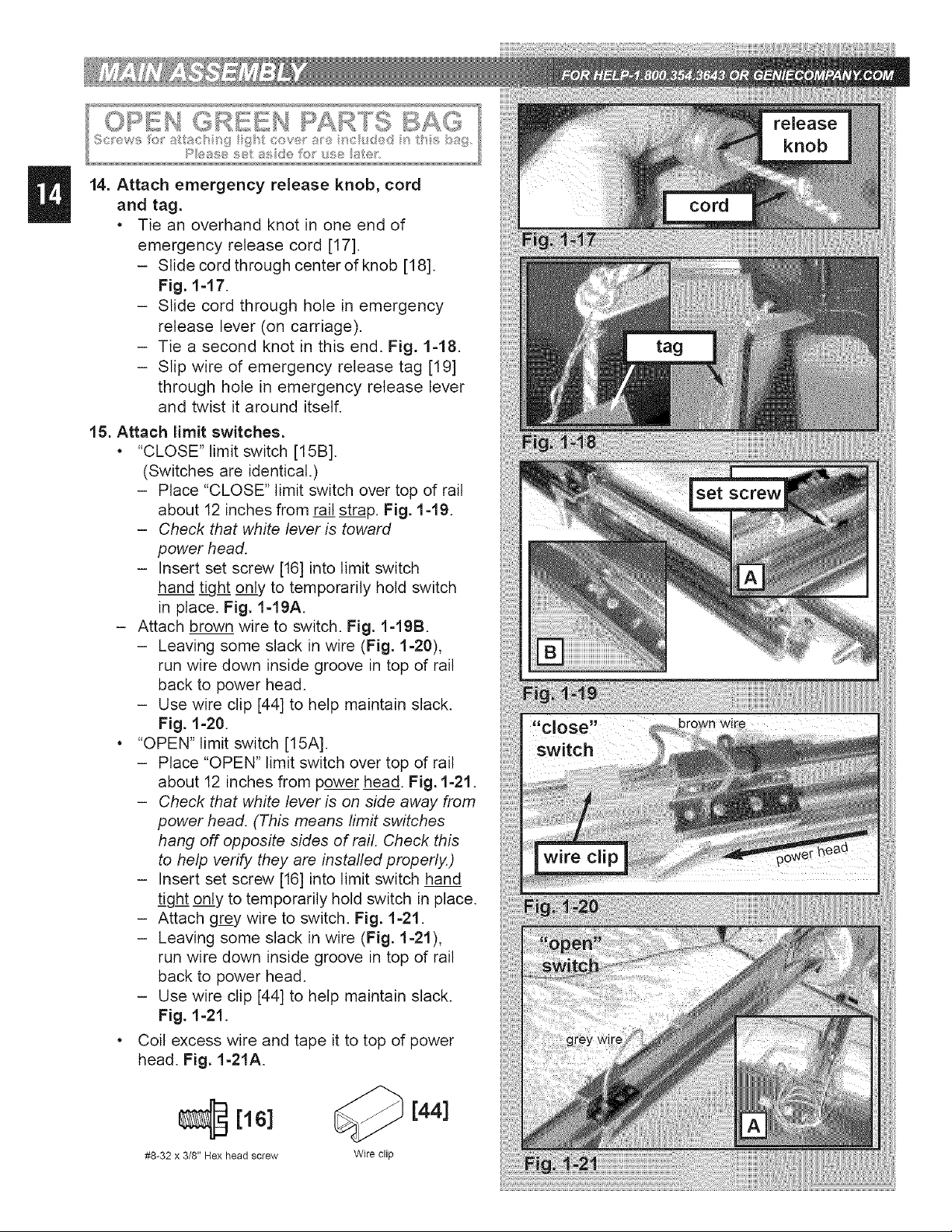
14. Attach emergency release knob, cord
and tag.
• Tie an overhand knot in one end of
emergency release cord [17].
- Slide cord through center of knob [18].
Fig. 1=17.
- Slide cord through hole in emergency
release lever (on carriage).
- Tie a second knot in this end. Fig. 1-18.
- Slip wire of emergency release tag [19]
through hole in emergency release lever
and twist it around itself.
15. Attach limit switches.
• "CLOSE" limit switch [15B].
(Switches are identical.)
- Place "CLOSE" limit switch over top of rail
about 12 inches from rail strap. Fig. 1-19.
- Check that white lever is toward
power head.
- Insert set screw [16] into limit switch
hand tight only to temporarily hold switch
in place. Fig. 1-19A.
- Attach brown wire to switch. Fig. 1-19B.
- Leaving some slack in wire (Fig. 1=20),
run wire down inside groove in top of rail
back to power head.
- Use wire clip [44] to help maintain slack.
Fig. 1=20.
"OPEN" limit switch [15A].
- Place "OPEN" limit switch over top of rail
about 12 inches from power head. Fig. 1=21.
- Check that white lever is on side away from
power head. (This means limit switches
hang off opposite sides of rail. Check this
to help verify they are installed properly.)
- Insert set screw [16] into limit switch hand
tight only to temporarily hold switch in place.
- Attach grey wire to switch. Fig. 1=21.
- Leaving some slack in wire (Fig. 1=21),
run wire down inside groove in top of rail
back to power head.
- Use wire clip [44] to help maintain slack.
Fig. 1-21.
Coil excess wire and tape it to top of power
head. Fig. 1-21A.
[16] [44]
#8-32 x 3/8" Hex head screw Wire clip
Loading ...
Loading ...
Loading ...