
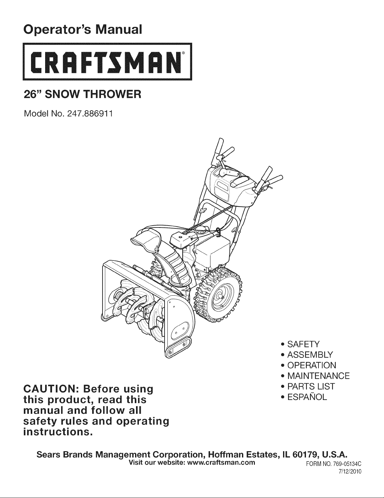
Operator's Manual
CRRFr MRN
26" SNOW THROWER
Model No. 247.886911
CAUTION: Before using
this product, read this
manual and follow all
safety rules and operating
instructions.
o SAFETY
ASSEMBLY
OPERATION
MAINTENANCE
PARTS LIST
o ESPANOL
Sears Brands Management Corporation, Hoffman Estates, IL 60179, U.S.A.
Visit our website: www.craftsman.com FORMNO.769-05134C
7/12/2010
WarrantyStatement.................... Page2
SafeOperationPractices.............. Pages3-6
SafetyLabels......................... Page7
Assembly......................... Pages8-13
Operation........................ Pages14-17
Service&Maintenance.............. Pages18-23
Off-SeasonStorage................... Page24
Troubleshooting...................... Page25
PartsList......................... Pages26-36
RepairProtectionAgreement............ Page41
Espa_ol............................. Page42
ServiceNumbers................... BackPage
CRAFTSMANTWOYEARFULL WARRANTY
FORTWOYEARSfromthedateofpurchase,thisproductiswarrantedagainstanydefectsinmaterialorworkmanship.Defectiveproductwill
receivefreerepairorfreereplacementifrepairisunavailable.
Thiswarrantyisvoidifthisproductiseverusedwhileprovidingcommercialservicesorifrentedtoanotherperson.
Forwarrantycoverage details to obtain repairor replacement,visit the website: www.craftsman.com
This warranty covers ONLYdefects in material and workmanship. Warranty coverage does NOTinclude:
• Expendableitemsthatcan wearoutfromnormalusewithinthewarrantyperiod,includingbut not limitedto augers,auger paddles,drift
cutters,skidshoes,shaveplate,shearpins, spark plug,air cleaner,belts,andoil filter.
• Standardmaintenanceservicing,oilchanges,or tune-ups.
• Tire replacementor repaircausedby puncturesfrom outsideobjects,such as nails,thorns,stumps,or glass.
Tireor wheelreplacementor repairresultingfromnormalwear,accident,orimproperoperationor maintenance.
Repairsnecessarybecauseof operatorabuse, includingbutnot limitedto damagecausedby over-speedingthe engine,or fromimpacting
objectsthat bendthe frame,augershaft,etc.
• Repairsnecessarybecauseof operatornegligence,includingbut not limitedto,electricalandmechanicaldamagecausedby improper
storage,failureto usethe propergradeandamountof engineoil, or failureto maintainthe equipmentaccordingto the instructionscontained
inthe operator'smanual.
• Engine(fuelsystem)cleaningor repairscausedbyfuel determinedto becontaminatedor oxidized(stale).In general,fuel shouldbeused
within30 daysof itspurchasedate.
Normaldeteriorationandwearof the exteriorfinishes,or productlabelreplacement.
Thiswarrantygivesyou specificlegal rights,andyou mayalso haveotherrightswhichvary from stateto state.
Sears Brands Management Corporation, Hoffman Estates, IL 60179
EngineOilType: SAE5W-30
EngineOilCapacity: 20ounces
FuelCapacity: 3 Quarts
SparkPlug: TorchF6RTC
SparkPlugGap: .020"to .030"
Model Number.................................................................
Serial Number.................................................................
Dateof Purchase .............................................................
Recordthe modelnumber,serialnumber
anddateof purchaseabove
© Sears Brands,LLC
2
Thissymbolpointsout importantsafetyinstructionswhich,if not
followed,couldendangerthepersonalsafetyand/orpropertyof
yourselfand others. Readandfollowall instructionsin thismanual
beforeattemptingto operatethismachine.Failureto complywith
theseinstructionsmayresultin personalinjury.Whenyou seethis
symbol,HEEDITSWARNING!
CALIFORNIA PROPOSITION 65
EngineExhaust,someof itsconstituents,andcertainvehicle
componentscontainoremit chemicalsknownto Stateof California
to cause cancerand birthdefectsorotherreproductiveharm,
Thismachinewas builtto beoperatedaccordingto the safeopera-
tion practicesin this manual.As with anytypeof powerequipment,
carelessnessor error on the partof the operatorcan resultin serious
injury.Thismachineis capableof amputatingfingers,hands,toes
andfeet and throwingdebris.Failureto observethe followingsafety
instructionscouldresultin seriousinjuryor death.
Your Responsibility--Restrict the useof this powermachineto
personswho read,understandand followthewarningsand instruc-
tionsin thismanualand on the machine,
SAVE THESE INSTRUCTIONS!
TRAiNiNG
• Read,understand,and followall instructionson the machineand
in themanual(s)beforeattemptingto assembleandoperate.
Failureto do socan resultinseriousinjuryto the operatorand/
orbystanders.Keepthismanualin a safeplaceforfutureand
regularreferenceandfor orderingreplacementparts. Forques-
tionscall, 1-800-4MY-HOME.
• Befamiliarwith all controlsand their properoperation.Knowhow
to stop the machineanddisengagethemquickly.
Neverallowchildrenunder 14yearsof age to operatethis
machine.Children14andover shouldreadandunderstandthe
instructionsand safe operationpracticesin thismanualand on
the machineand be trainedandsupervisedby anadult.
Neverallowadultsto operatethis machinewithoutproper
instruction.
• Thrownobjectscan causeseriouspersonalinjury.Planyour
snow-throwingpatternto avoiddischargeof materialtoward
roads,bystandersandthe like.
Keepbystanders,pets andchildrenat least75 feet from the
machinewhile itisin operation.Stopmachineifanyoneenters
the area.
Exercisecautionto avoidslippingor falling,especiallywhen
operatingin reverse.
PREPARATION
Thoroughlyinspecttheareawherethe equipmentis to beused.
Removeall doormats,newspapers,sleds,boards,wiresand other
foreignobjects,whichcouldbe trippedoverorthrownby the auger/
impeller.
Alwayswear safetyglassesor eyeshieldsduringoperationand
while performingan adjustmentor repairto protectyoureyes.
Thrownobjectswhichricochetcancauseseriousinjuryto the
eyes.
Donot operatewithoutwearingadequatewinteroutergarments.
Donot wearjewelry,longscarvesor otherlooseclothing,which
could becomeentangledinmovingparts.Wearfootwearwhich
will improvefooting on slipperysurfaces.
Usea groundedthree-wireextensioncordand receptaclefor all
machineswith electricstartengines.
Disengageall controlleversbeforestartingthe engine.
Adjustcollectorhousingheightto cleargravelorcrushedrock
surfaces.
Neverattemptto make anyadjustmentswhileengineis running,
exceptwherespecificallyrecommendedinthe operator'smanual.
Letengineandmachineadjustto outdoortemperaturebefore
startingto clearsnow.
3
Safe Handling of Gasoline
Toavoidpersonalinjuryor propertydamageuseextremecare in
handlinggasoline.Gasolineis extremelyflammableand the vaporsare
explosive.Seriouspersonalinjurycan occurwhengasolineis spilled
onyourselfor yourclotheswhichcan ignite.Washyour skinand
changeclothesimmediately.
• Useonly anapprovedgasolinecontainer.
• Extinguishall cigarettes,cigars,pipesandother sources
of ignition.
• Neverfuelmachineindoors.
• Neverremovegas capor addfuel whilethe engineis hot
or running.
• Allowengineto coolat leasttwo minutesbeforerefueling.
• Neveroverfill fueltank. Filltank to no morethan1/2inch
belowbottomof filler neckto providespacefor fuel
expansion.
• Replacegasolinecap and tightensecurely.
• If gasolineis spilled,wipeit offthe engineandequipment.
Movemachineto anotherarea.Wait5 minutesbefore
startingthe engine.
• Neverstorethe machineor fuel containerinsidewhere
thereis an open flame,sparkor pilotlight (e.g.furnace,
waterheater,spaceheater,clothesdryer etc.).
• Allowmachineto cool at least5 minutesbeforestoring.
• Neverfill containersinsidea vehicleor ona truckor trailer
bedwith a plasticliner.Alwaysplacecontainerson the
groundawayfromyourvehiclebeforefilling.
• If possible,removegas-poweredequipmentfrom thetruck
ortrailerand refuelit on the ground.If thisis not possible,
then refuelsuchequipmenton a trailerwitha portable
container,ratherthan from a gasolinedispensernozzle.
• Keepthe nozzleincontactwith the rimof the fueltank or
containeropeningat all timesuntil fuelingis complete.Do
notuse a nozzlelock-opendevice.
OPERATION
• Do not puthandsorfeet near rotatingparts,in the auger/impeller
housingor chuteassembly.Contactwith the rotatingpartscan
amputatehandsandfeet.
• Theauger/impellercontrolleveris a safetydevice.Neverbypass
itsoperation.Doingso makesthe machineunsafeandmaycause
personalinjury.
• Thecontrolleversmustoperateeasilyin bothdirectionsand
automaticallyreturnto the disengagedpositionwhenreleased.
• Neveroperatewith a missingor damagedchuteassembly.Keep
all safetydevicesin placeandworking.
• Neverrunan engine indoorsor ina poorlyventilatedarea. Engine
exhaustcontainscarbonmonoxide,an odorlessanddeadlygas.
• Do notoperatemachinewhileunder the influenceof alcoholor
drugs.
• Mufflerand enginebecomehotandcan causea burn.Do not
touch.Keepchildrenaway.
• Exerciseextremecautionwhenoperatingon orcrossinggravel
surfaces.Stay alertfor hiddenhazardsor traffic.
• Exercisecautionwhenchangingdirectionand whileoperatingon
slopes.
• Planyoursnow-throwingpatternto avoiddischargetowards
windows,walls,carsetc. Thus,avoidingpossibleproperty
damageor personalinjurycausedby a ricochet.
• Neverdirect dischargeat children,bystandersand petsor allow
anyoneinfront of the machine.
• Donot overloadmachinecapacityby attemptingto clearsnowat
too fastof a rate.
• Neveroperatethis machinewithoutgoodvisibility or light. Always
be sureof yourfootingand keepa firmholdon the handles.Walk,
neverrun.
• Disengagepowerto theauger/impellerwhentransportingor not
in use.
• Neveroperatemachineat hightransportspeedson slippery
surfaces.Lookdownand behindand usecare whenbackingup.
• If the machineshouldstart to vibrateabnormally,stopthe engine,
disconnectthe spark plugwire andgroundit againstthe engine.
Inspectthoroughlyfor damage.Repairanydamagebefore
startingandoperating.
• Disengageall controlleversandstop enginebeforeyouleave
the operatingposition(behindthe handles).Wait untilthe auger/
impellercomesto a completestopbeforeuncloggingthechute
assembly,makingany adjustments,or inspections.
• Neverput yourhandin the dischargeor collectoropenings.Do
not unclogchuteassemblywhileengineis running.Shutoff
engineand remainbehindhandlesuntilall movingpartshave
stoppedbeforeunclogging.
• Useonly attachmentsandaccessoriesapprovedby the manufac-
turer (e.g.wheelweights,tire chains,cabsetc.).
• Whenstartingengine,pull cord slowlyuntilresistanceis felt, then
pull rapidly.Rapidretractionof startercord(kickback)will pull
handand armtowardenginefasterthan youcan let go. Broken
bones,fractures,bruisesor sprainscould result.
• If situationsoccur whichare notcoveredinthis manual,use care
andgood judgment.ContactCustomerSupportfor assistance
andthe nameof your nearestservicingdealer.
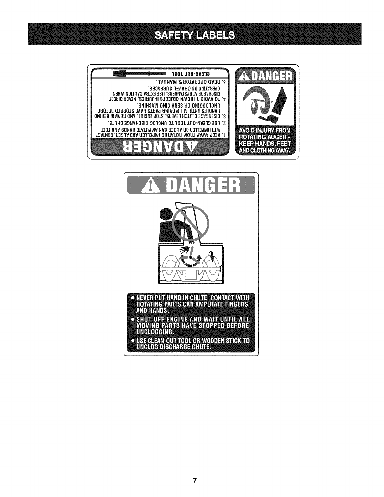
CLEARING A CLOGGED DISCHARGE CHUTE
Handcontactwith the rotatingimpellerinsidethe dischargechute
is the mostcommoncauseof injuryassociatedwith snowthrowers.
Neveruse yourhand to cleanout thedischargechute.
Toclear thechute:
1. SHUTTHEENGINEOFF!
2. Wait 10secondsto be surethe impellerbladeshavestopped
rotating.
3. Alwaysusea clean-outtool,not yourhands.
4
MAINTENANCE & STORAGE
• Nevertamperwithsafetydevices.Checktheirproperoperation
regularly.Referto the maintenanceand adjustmentsectionsof
thismanual.
• Beforecleaning,repairing,or inspectingmachinedisengageall
controlleversandstop the engine.Wait untilthe auger/impeller
cometo a completestop.Disconnectthe sparkplugwireand
groundagainsttheengineto preventunintendedstarting.
Checkboltsand screwsfor propertightnessat frequentintervals
to keepthe machineinsafe workingcondition.Also,visually
inspectmachinefor anydamage.
Do notchangetheenginegovernorsettingor over-speedthe
engine.Thegovernorcontrolsthe maximumsafeoperatingspeed
of the engine.
Snowthrowershaveplatesand skidshoesaresubjectto wear
anddamage.Foryoursafetyprotection,frequentlycheckall
componentsand replacewithoriginalequipmentmanufacturer's
(OEM)partsonly."Useof parts whichdo not meetthe original
equipmentspecificationsmayleadto improperperformanceand
compromisesafety!"
Checkcontrolleversperiodicallyto verifythey engageanddisen-
gageproperlyandadjust,if necessary.Referto the adjustment
sectioninthisoperator'smanualfor instructions.
Maintainor replacesafetyandinstructionlabels,as necessary.
• Observeproperdisposallawsand regulationsfor gas,oil,etc. to
protectthe environment.
Priorto storing,run machinea few minutestoclear snowfrom
machineand preventfreezeup of auger/impeller.
Neverstorethe machineor fuel containerinsidewherethereisan
openflame,sparkorpilot lightsuch as a waterheater,furnace,
clothesdryer etc.
Alwaysreferto the operator'smanualfor properinstructionson
off-seasonstorage.
Checkfuelline,tank, cap,andfittingsfrequentlyfor cracksor
leaks.Replaceif necessary.
Do notcrank enginewithsparkplugremoved.
Accordingto the ConsumerProductsSafetyCommission(CPSC)
andthe U.S.EnvironmentalProtectionAgency(EPA),this product
hasan AverageUsefulLifeof seven(7)years,or 60 hoursof
operation.At the endof theAverageUsefulLifehavethe machine
inspectedannuallybyan authorizedservicedealerto ensurethat
allmechanicalandsafetysystemsareworkingproperlyand not
wornexcessively.Failureto do so can resultinaccidents,injuries
ordeath.
DO NOT MODIFY ENGINE
Toavoidseriousinjuryor death,do not modifyengineinany way.
Tamperingwiththe governorsettingcanlead to a runawayengineand
causeit to operateat unsafespeeds.Nevertamperwithfactorysetting
of engine governor.
NOTICE REGARDING EMISSIONS
Engineswhich are certifiedtocomplywithCaliforniaandfederal
EPAemissionregulationsfor SORE(SmallOff RoadEquipment)are
certifiedto operateon regularunleadedgasoline,and mayinclude
the followingemissioncontrolsystems:EngineModification(EM),
OxidizingCatalyst(OC), SecondaryAir Injection(SAI)and ThreeWay
Catalyst(TWO)if so equipped.
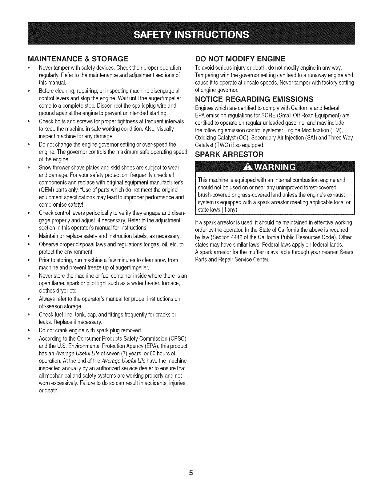
SPARK ARRESTOR
Thismachineisequippedwith an internalcombustionengineand
shouldnotbe usedonor nearany unimprovedforest-covered,
brush-coveredor grass-coveredlandunlessthe engine'sexhaust
systemisequippedwith a sparkarrestormeetingapplicablelocalor
statelaws(if any)
Ifa sparkarrestoris used, it shouldbe maintainedin effectiveworking
orderby theoperator.Inthe State of Californiathe aboveis required
bylaw (Section4442 of the CaliforniaPublicResourcesCode).Other
statesmayhavesimilarlaws. Federallawsapplyonfederallands.
A sparkarrestorfor the muffleris availablethroughyournearestSears
PartsandRepairServiceCenter.
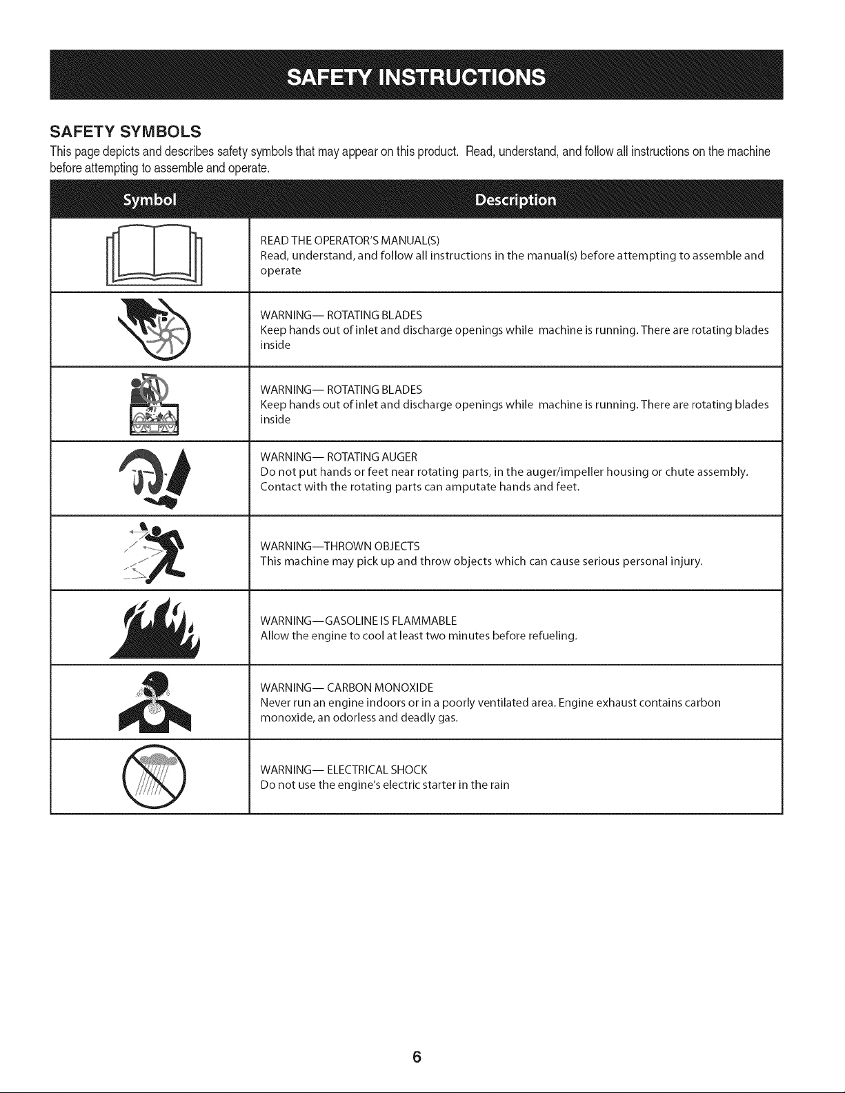
SAFETY SYMBOLS
Thispagedepictsand describessafetysymbolsthatmayappear on this product. Read,understand,and followall instructionson the machine
beforeattemptingto assembleandoperate.
. +
i
i
'JIp
READ THE OPERATOR'S MANUAL(S)
Read, understand, and follow all instructions in the manual(s) before attempting to assemble and
operate
WARNING-- ROTATING BLADES
Keep hands out of inlet and discharge openings while machine is running. There are rotating blades
inside
WARNING-- ROTATING BLADES
Keep hands out of inlet and discharge openings while machine is running. There are rotating blades
inside
WARNING-- ROTATING AUGER
Do not put hands or feet near rotating parts, in the auger/impeller housing or chute assembly.
Contact with the rotating parts can amputate hands and feet.
WARNING--THROWN OBJECTS
This machine may pick up and throw objects which can cause serious personal injury.
WARNING--GASOLINE IS FLAMMABLE
Allow the engine to cool at least two minutes before refueling.
WARNING-- CARBON MONOXIDE
Never run an engine indoors or in a poorly ventilated area. Engine exhaust contains carbon
monoxide, an odorless and deadly gas+
WARNING-- ELECTRICAL SHOCK
Do not use the engine's electric starter in the rain
6
1001 IIIO=NV]IO
"lVflNV_ S,UOIVU3dOQV3H"_
"S33VdUnS13MH9 NO9NilVU3dO
N3HMNOIIRVOVtdlX33SR"SU3ONVISIBlV 30UVHOSBO
13:IUIQH:IA:IN'S3iURrNi $13]F80 NMOUH1QiOAV01 "t_
7]NiHOV_ 9Ni31Atd_SUO9Nigoo13NI'I
:IUO:J3gQ3dd01S3MH SIUVd9HJAOI_1W lJlHn S31QNVH
QNIH38NiV_3UQNV'::lNiON::ldOlS'SH3A:rlH31R133_)VON:lSJ(]"_
":11AH33OSVHOSJQ90"13NI301 1001 lflO=NV:rl3 :lSfl"_
"l:GdQNV8OHVH:11Vlrld_VHVOU39flV}JO_13l13dL_lHIIM
IOVlN037d3911VQNV1:131"13dlAll9NilVlOldINOU:IIVMV d:13)t"L
7
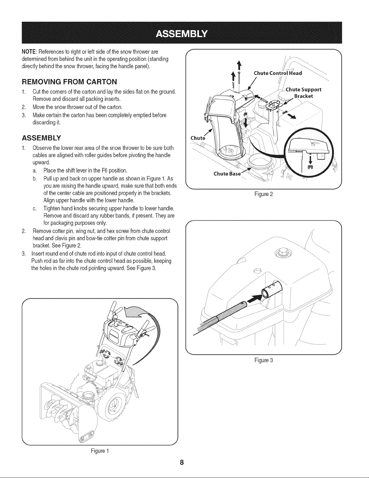
NOTE:Referencesto rightorleft sideof the snowthrowerare
determinedfrombehindthe unit in the operatingposition(standing
directlybehindthe snow thrower,facingthe handlepanel).
REMOVING FROM CARTON
1. Cut the cornersof thecartonandlay the sidesflaton the ground.
Removeand discard allpackinginserts.
2. Movethe snowthrowerout of thecarton.
3. Makecertainthe cartonhas beencompletelyemptiedbefore
discardingit.
ASSEMBLY
1. Observethe lowerreararea of the snowthrowerto besure both
cablesarealignedwith rollerguidesbeforepivotingthe handle
upward.
a. Placethe shiftleverin the F6position.
b. Pull up andbackon upperhandleas shownin Figure1.As
youare raisingthe handleupward,make surethat bothends
of the centercablearepositionedproperlyinthe brackets.
Alignupperhandlewith the lowerhandle.
c. Tightenhandknobssecuringupperhandleto lowerhandle.
Removeand discard any rubberbands,if present.Theyare
for packagingpurposesonly.
2. Removecotterpin,wing nut, and hexscrewfromchutecontrol
headand clevispin and bow-tiecotterpinfromchutesupport
bracket.SeeFigure2.
3. Insertroundendof chuterodinto inputof chute controlhead.
Pushrodas far intothe chutecontrolheadas possible,keeping
the holesin the chuterod pointingupward.SeeFigure3.
Chute Control Head
Support
Bracket
Chute Base"
Figure2
f
/
\
Figure3
_J
Figure1
8
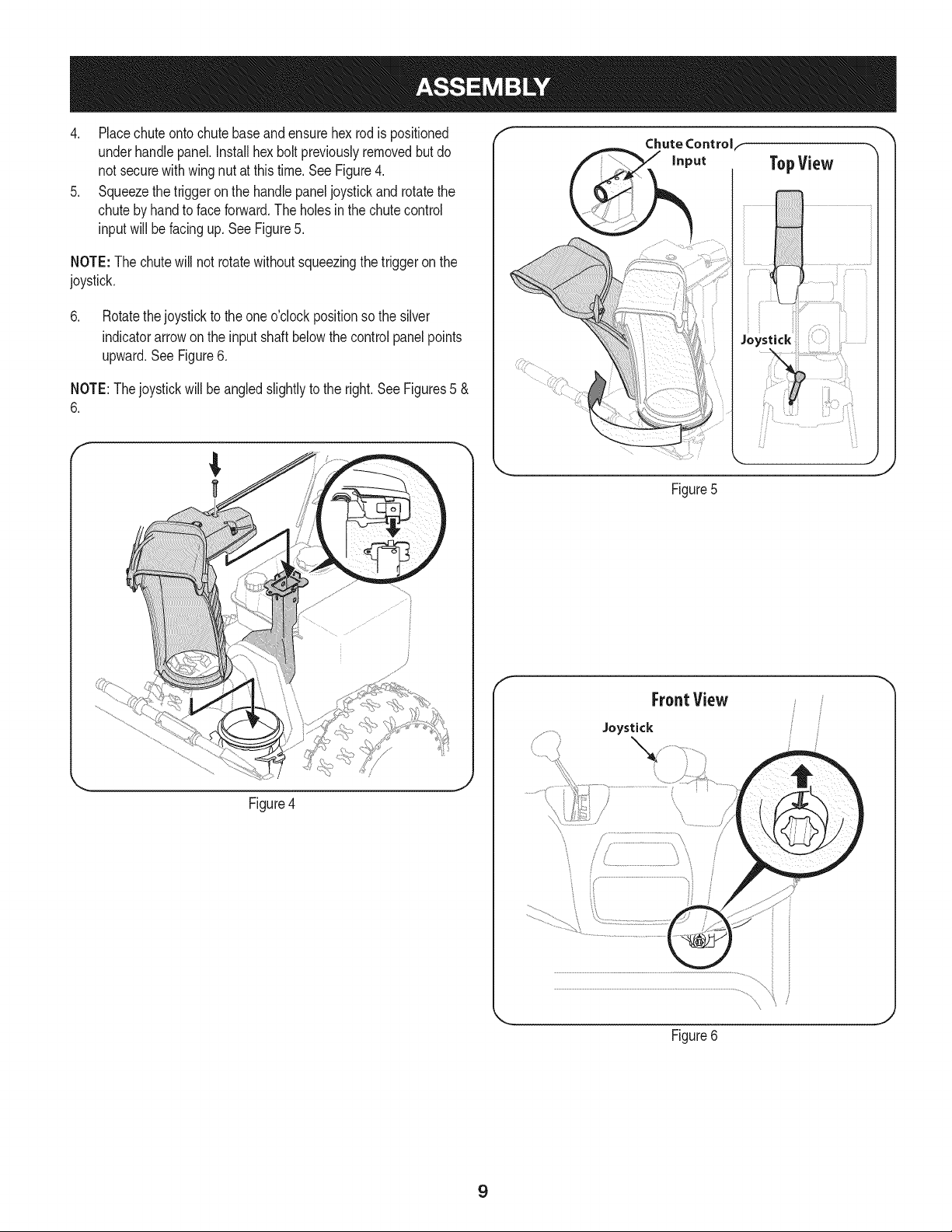
4. Placechuteontochutebaseandensurehexrodis positioned
underhandlepanel.Installhex boltpreviouslyremovedbut do
not securewith wingnut at this time.See Figure4.
5. Squeezethetriggeron the handlepaneljoystickand rotatethe
chutebyhand to faceforward.The holesin the chutecontrol
inputwill be facing up. SeeFigure5.
NOTE:The chutewill not rotatewithoutsqueezingthe triggeronthe
joystick.
6. Rotatethejoystickto the oneo'clockpositionso the silver
indicatorarrowonthe inputshaft belowthe controlpanel points
upward.SeeFigure6.
NOTE:Thejoystickwillbe angledslightlyto the right.SeeFigures5 &
6.
Figure4
f
Chute Controlf
Figure5
f
FrontView
Joystick
Figure6
J
9
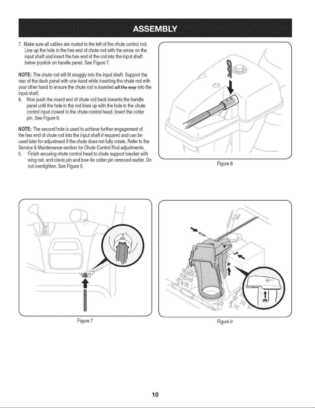
7. Makesureall cablesare routedto the leftof thechute controlrod.
Lineup the holeinthe hexendof chuterodwith the arrowonthe
inputshaftandinsert the hexendof the rod into the inputshaft
belowjoystickon handlepanel.SeeFigure7.
NOTE:Thechuterod will fit snugglyintothe inputshaft.Supportthe
rearof the dash panelwith onehandwhileinsertingthechuterod with
your otherhandto ensurethechuterod is insertedall the way intothe
inputshaft.
8. Nowpushthe roundend of chuterod backtowardsthe handle
paneluntilthe hole in the rod linesupwiththe holein the chute
controlinputclosestto the chutecontrolhead. Insertthe cotter
pin.SeeFigure8.
NOTE:The secondholeis usedto achievefurtherengagementof
the hex endof chuterodintothe inputshaft if requiredand can be
usedlaterforadjustmentif thechutedoesnot fullyrotate.Refertothe
Service& Maintenancesectionfor ChuteControlRodadjustments.
9. Finishsecuringchute controlheadto chutesupportbracketwith
wingnut,and clevispin and bow-tiecotter pinremovedearlier.Do
notovertighten.SeeFigure9.
/i _
.J
Figure8
/
/
' .....................................................i_"i
}
Figure7
Figure9
10
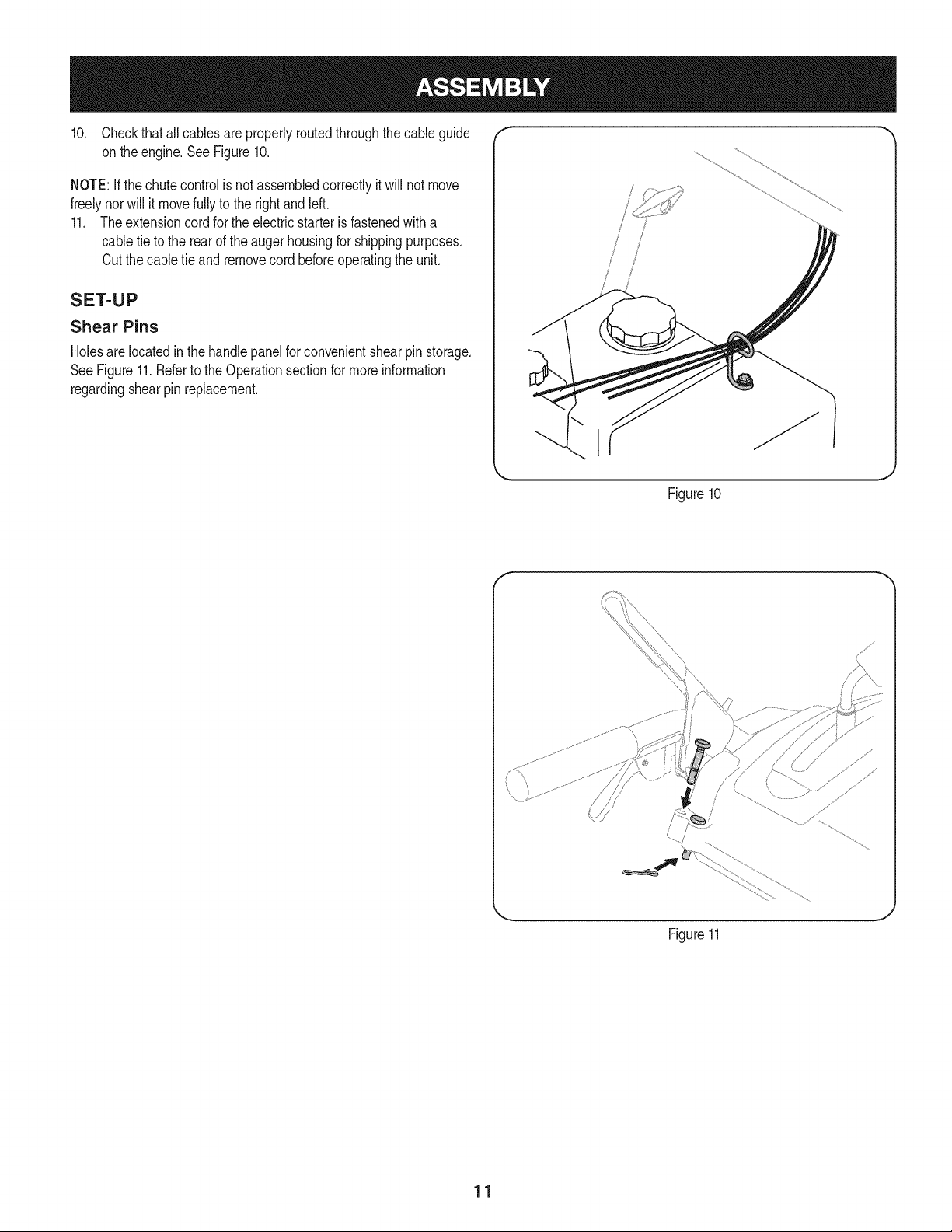
10. Checkthat allcablesareproperlyroutedthroughthecable guide "_
on theengine.SeeFigure10.
NOTE:Ifthe chutecontrolis not assembledcorrectlyit will not move
freelynorwill it movefullyto the rightandleft.
11. Theextensioncord forthe electricstarteris fastenedwitha
cabletie to the rearof the augerhousingfor shippingpurposes.
Cutthe cabletie and removecord beforeoperatingthe unit.
SET-UP
Shear Pins
Holesare locatedinthe handlepanelfor convenientshearpin storage.
SeeFigure11.Referto the Operationsectionfor moreinformation
regardingshearpin replacement.
/
i
/
/
I
Figure10
f
Figure11
J
11
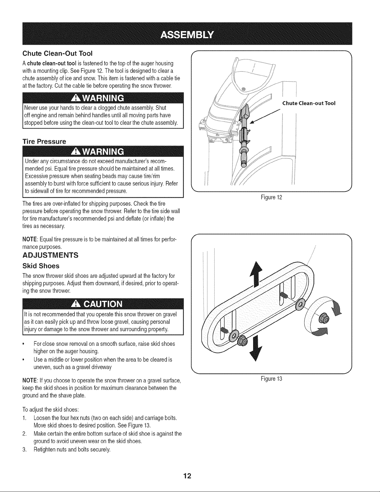
Chute Clean=Out Tool
Achute clean-out tool is fastenedto the top of the augerhousing
witha mountingclip.SeeFigure12.The tool is designedto cleara
chuteassemblyof ice andsnow.Thisitemis fastenedwitha cabletie
at the factory.Cut thecable tie beforeoperatingthe snowthrower.
loft _1 .allmovingpartshave
stoppedbeforeusingthe clean-outtool to clearthe chuteassembly.
Tire Pressure
Underanycircumstancedo notexceedmanufacturer'srecom-
mendedpsi. Equaltire pressureshouldbe maintainedat all times.
Excessivepressurewhenseatingbeadsmaycausetire/rim
assemblyto burst with forcesufficientto causeseriousinjury.Refer
to sidewallof tirefor recommendedpressure.
Thetiresare over-inflatedfor shippingpurposes.Checkthetire
pressurebeforeoperatingthe snowthrower.Referto the tire sidewall
for tiremanufacturer'srecommendedpsianddeflate(or inflate)the
tiresas necessary.
NOTE:Equaltire pressureis to be maintainedat alltimesfor perfor-
mancepurposes.
ADJUSTMENTS
Skid Shoes
The snowthrowerskid shoesare adjustedupwardat thefactory for
shippingpurposes.Adjustthemdownward,if desired,priorto operat-
ingthe snowthrower.
It is not recommendedthatyouoperatethis snowthrowerongravel
as it can easilypick up andthrowloosegravel,causingpersonal
njuryordamageto the snowthrowerand surroundng property.
• Forclosesnow removalon a smoothsurface,raiseskidshoes
higheronthe augerhousing.
• Usea middleor lowerpositionwhentheareato be clearedis
uneven,suchas a graveldriveway
NOTE:If youchooseto operatethe snowthrowerona gravelsurface,
keepthe skid shoesin positionfor maximumclearancebetweenthe
groundandthe shaveplate.
Chutedean=out Tool
Figure12
Figure13
Toadjustthe skid shoes:
1. Loosenthe four hexnuts(two on each side)andcarriagebolts.
Moveskidshoesto desiredposition.See Figure13.
2. Makecertainthe entirebottomsurfaceof skidshoeis againstthe
groundto avoidunevenwearonthe skidshoes.
3. Retightennutsand boltssecurely.
12
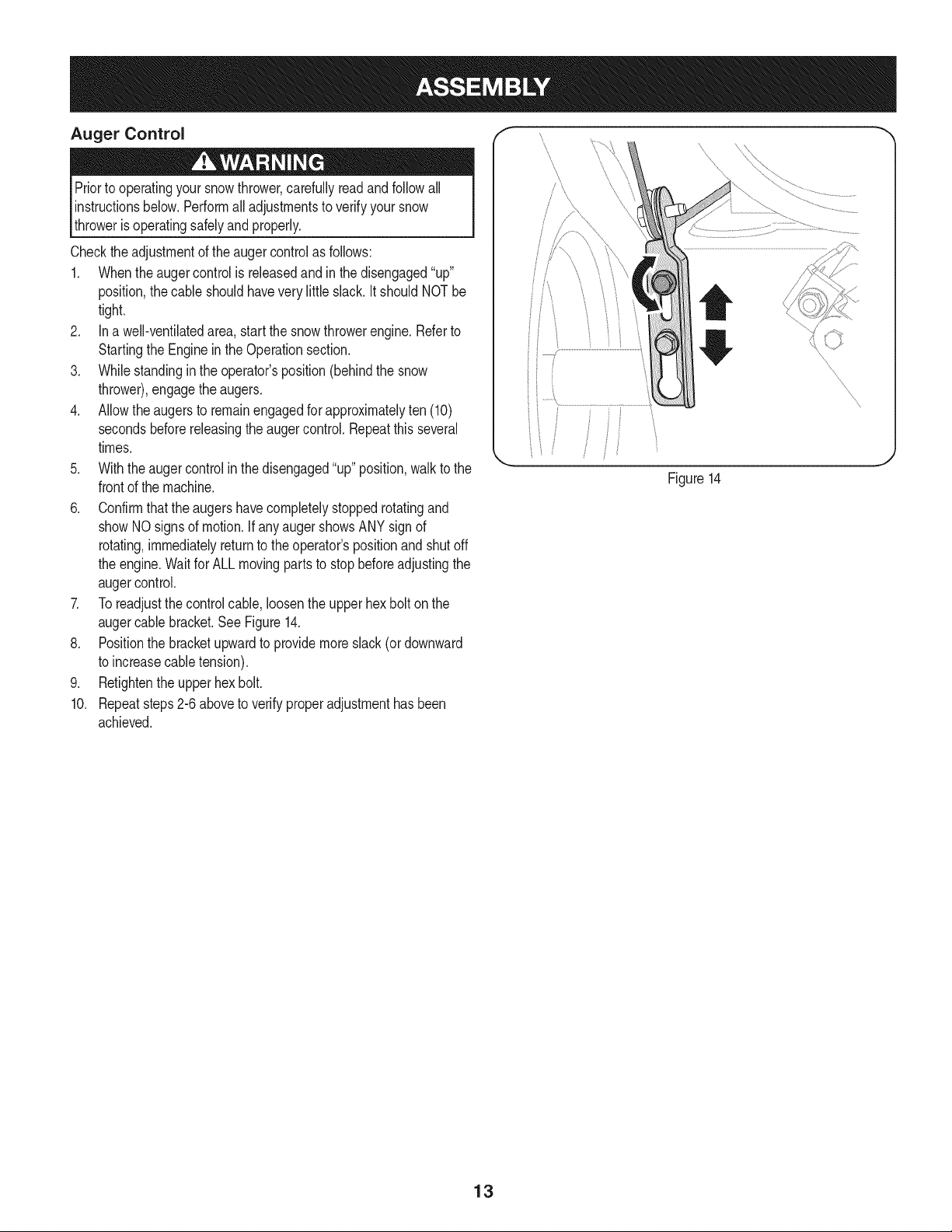
Priorto operatingyoursnowthrower,carefullyreadand followall
instructionsbelow.Performall adjustmentsto verifyyoursnow
throweris operatingsafelyandproperly.
Checktheadjustmentof the augercontrolas follows:
1. Whentheaugercontrolis releasedand in the disengaged"up"
position,the cableshouldhavevery littleslack. It shouldNOTbe
tight.
2. In a well-ventilatedarea,start the snowthrowerengine.Referto
Startingthe Enginein the Operationsection.
3. Whilestandingin the operator'sposition(behindthe snow
thrower),engagethe augers.
4. Allowtheaugersto remainengagedfor approximatelyten (10)
secondsbeforereleasingthe augercontrol.Repeatthisseveral
times.
5. With theauger controlin thedisengaged"up" position,walkto the
frontof the machine.
6. Confirmthatthe augershavecompletelystoppedrotatingand
showNOsignsof motion.If anyaugershowsANY signof
rotating,immediatelyreturnto the operator'spositionandshutoff
the engine.Waitfor ALL movingparts to stopbeforeadjustingthe
augercontrol.
7. Toreadjustthecontrolcable, loosentheupperhexbolt on the
augercablebracket.SeeFigure14.
8. Positionthe bracketupwardto providemoreslack(or downward
to increasecabletension).
9. Retightenthe upperhex bolt.
10. Repeatsteps2-6 aboveto verifyproperadjustmenthasbeen
achieved.
Figure14
13
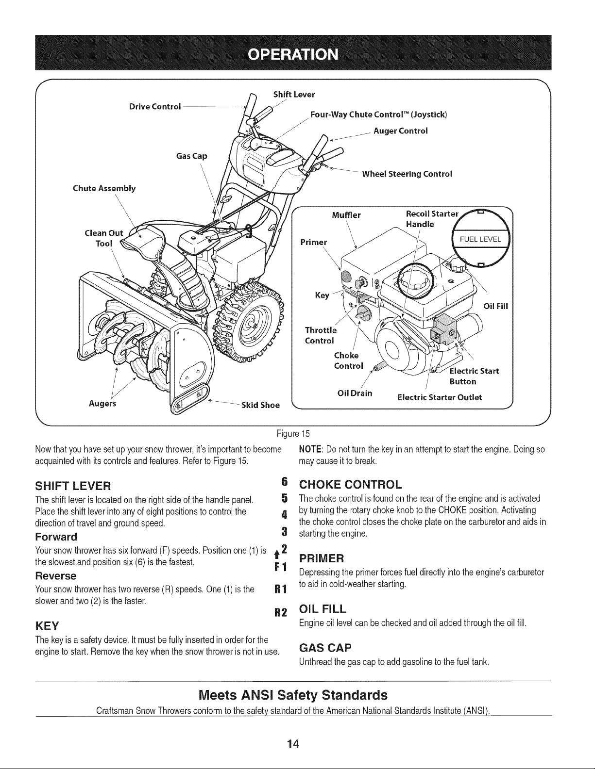
f
Drive Control
ChuteAssembly
\\\\
Clean Out
Tool
\
Augers
Gas Cap
Skid Shoe
Shift Lever
J
/ Four=WayChuteControP (Joystick)
/-
j_ Auger Control
"..........WheelSteeringControl
Primer
Muffler RecoilStarter
,\\ nd e
Key
Fill
Throttle
Control
Choke
Control
:lectric Start
Button
/
Oil Drain Electric Starter Outlet
J
Figure15
Nowthat youhavesetup yoursnowthrower,it'simportantto become NOTE: Donot turnthe keyinan attemptto startthe engine.Doingso
acquaintedwith itscontrolsand features.Referto Figure15. maycauseit to break.
SHIFT LEVER
The shiftleveris locatedonthe rightsideof the handle panel.
Placethe shiftleverinto anyof eightpositionsto controlthe
directionof travel and groundspeed.
Forward
6 CHOKE CONTROL
5 The chokecontrolisfoundon the rearof the engineand is activated
4 by turningthe rotarychokeknobto the CHOKEposition.Activating
the chokecontrolclosesthe chokeplateon thecarburetorand aids in
3 startingthe engine.
Yoursnowthrowerhas six forward(F) speeds.Positionone(1)is t 2
the slowestand positionsix (6) is the fastest. F 1
Reverse
Yoursnowthrowerhastwo reverse(R) speeds.One(1) is the
slowerandtwo (2) is the faster.
KEY
The keyisa safetydevice.It mustbefully insertedin orderfor the
engineto start. Removethe keywhenthe snowthroweris notin use.
PRIMER
Depressingthe primerforcesfueldirectlyintothe engine'scarburetor
to aid incold-weatherstarting.
OIL FILL
Engineoil levelcan becheckedandoiladdedthroughthe oil fill.
GAS CAP
Unthreadthe gas capto add gasolineto thefuel tank.
Meets ANSi Safety Standards
CraftsmanSnowThrowersconformto the safetystandardof the AmericanNationalStandardsInstitute(ANSI).
14
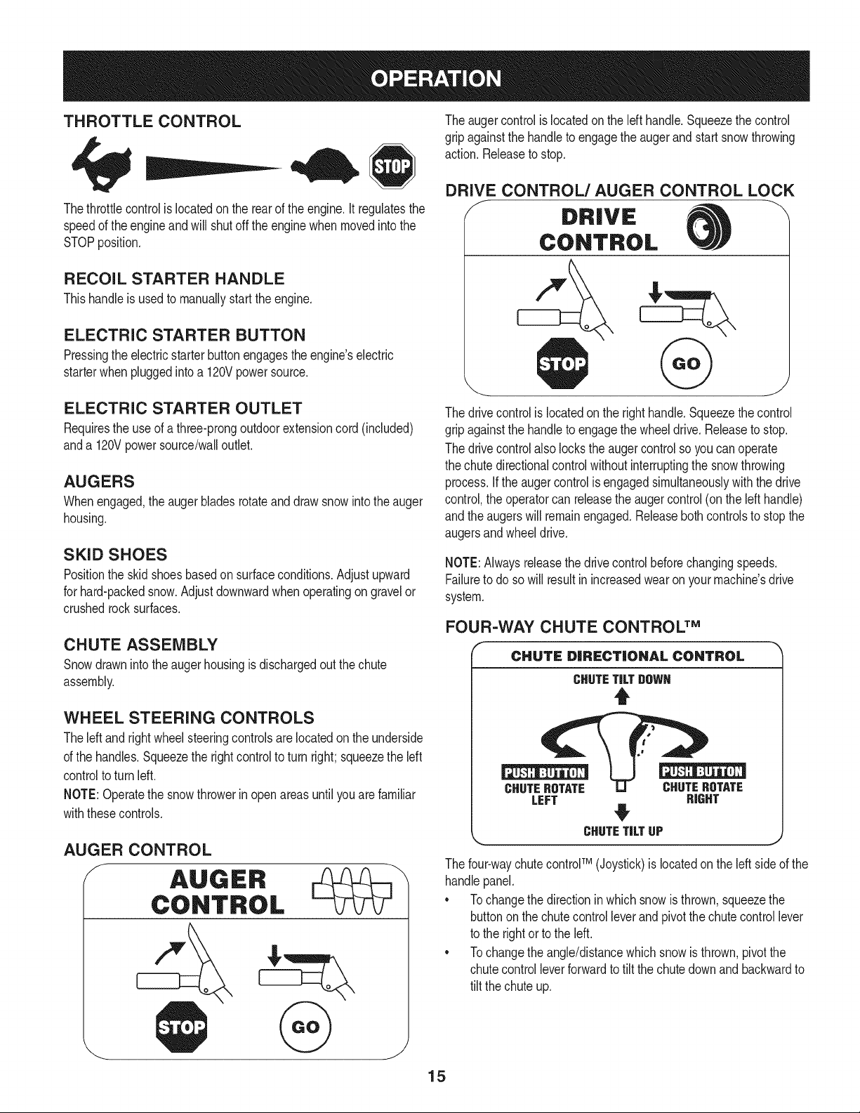
THROTTLE CONTROL
Thethrottlecontrolis locatedon the rearof the engine.It regulatesthe
speedof theengine andwill shutoff the enginewhenmovedintothe
STOPposition.
RECOIL STARTER HANDLE
Thishandleis usedto manuallystartthe engine.
ELECTRIC STARTER BUTTON
Pressingthe electricstarterbuttonengagesthe engine'selectric
starterwhenpluggedintoa 120Vpowersource.
ELECTRIC STARTER OUTLET
Requiresthe useof a three-prongoutdoorextensioncord(included)
anda 120Vpowersource/walloutlet.
AUGERS
Whenengaged,the augerbladesrotateand drawsnowintothe auger
housing.
SKID SHOES
Positionthe skid shoesbasedon surfaceconditions.Adjustupward
for hard-packedsnow.Adjustdownwardwhenoperatingon gravelor
crushedrocksurfaces.
CHUTE ASSEMBLY
Snowdrawninto theaugerhousingis dischargedout the chute
assembly.
WHEEL STEERING CONTROLS
Theleft andrightwheelsteeringcontrolsare locatedon theunderside
of the handles.Squeezethe rightcontrolto turn right;squeezethe left
controlto turn left.
NOTE:Operatethe snowthrowerinopen areasuntilyou arefamiliar
withthesecontrols.
AUGER CONTROL
The augercontrol is locatedon the lefthandle.Squeezethe control
gripagainstthe handleto engagethe augerand startsnowthrowing
action.Releaseto stop.
DRIVE CONTROL/AUGER CONTROL LOCK
DRIVE
CONTROL
The drivecontrolis locatedon the righthandle.Squeezethe control
gripagainstthe handleto engagethe wheeldrive.Releaseto stop.
The drivecontrolalso lockstheaugercontrolso youcan operate
the chute directionalcontrolwithoutinterruptingthe snowthrowing
process.If the augercontrolis engagedsimultaneouslywiththe drive
control,the operatorcan releasethe augercontrol (on the lefthandle)
andthe augerswill remainengaged.Releaseboth controlsto stopthe
augersandwheeldrive.
NOTE:Alwaysreleasethedrivecontrolbeforechangingspeeds.
Failureto do so will result in increasedwearon yourmachine'sdrive
system.
FOUR-WAY CHUTE CONTROL TM
CHUTE DiRECTiONAl CONTROL
CHUTETiLTgOWN
t
CHUTEROTATE CHUTEROTATE
LEFT RIGHT
#
CHUTETiLTUP J
The four-waychutecontroFM(Joystick)is locatedon theleft sideof the
handlepanel.
* Tochangethe directioninwhichsnowis thrown,squeezethe
buttononthe chutecontrolleverand pivotthe chutecontrol lever
to the rightor to the left.
* Tochangethe angle/distancewhichsnowisthrown,pivotthe
chutecontrolleverforwardto tiltthe chute downand backwardto
tilt the chuteup.
15
CLEAN-OUT TOOL
Neveruseyourhandsto cleara cloggedchuteassembly.Shut
loft engineand remainbehindhandlesuntil allmovingparts have
lstoppedbeforeusingtheclean-outtool to clearthe chuteassembly.
Thechuteclean-outtool is convenientlyfastenedto the rearof the
augerhousingwith a mountingclip. Shouldsnowandice become
lodgedin thechuteassemblyduringoperation,proceedas followsto
safelycleanthechuteassemblyand chute opening:
1. Releaseboththe AugerControlandthe DriveControl.
2. Stopthe engineby removingthe ignitionkey.
3. Removethe clean-outtoolfrom the clip whichsecuresit to the
rearof the augerhousing.
4. Use the shovel-shapedend of theclean-outtool to dislodgeand
scoopany snowand icewhichhasformedin andnearthechute
assembly.
5. Refastenthe clean-outtool to the mountingclip onthe rearof
theaugerhousing,reinsertthe ignitionkeyand startthe snow
thrower'sengine.
6. Whilestandingin the operator'sposition(behindthesnow
thrower),engagethe augercontrolfora fewsecondsto clear any
remainingsnowand ice fromthechute assembly.
BEFORE STARTING ENGINE
Read,understand,and followall instructionsandwarningson the
machineand inthismanualbeforeoperating.
Oil
Theunit was shippedwith oil inthe engine.Checkoil levelbefore
eachoperationto ensureadequateoil inthe engine.Forfurther
instructions,refertothe stepson page18.
NOTE:Besureto checkthe engineon a levelsurfacewiththe engine
stopped.
1. Removethe oil fillercap/dipstickandwipethe dipstickclean.
2. insertthe cap/dipstickintothe oil filler neck,butdo NOTscrewit
in.
3. Removethe oil fillercap/dipstick,ifthe levelislow,slowlyadd
oil (5W-30,with a minimumclassificationof SF/SG)untiloil level
registersbetweenhigh (H) andlow(L).
NOTE:Do notoverfill.Overfillingwith oil mayresultinenginesmoking,
hardstartingor sparkplugfouling.
4. Replaceand tighten cap/dipstickfirmlybeforestartingengine.
Gasoline
Useautomotivegasoline(unleadedor low leadedto minimizecombus-
tionchamberdeposits)with a minimumof 87octane.Gasolinewith
upto 10%ethanolor 15%MTBE(MethylTertiaryButyl Ether)canbe
used.Neverusean oil/gasolinemixtureor dirtygasoline.Avoidgetting
dirt,dust,or waterinthefuel tank. DO NOTuse E85gasoline.
• Refuelin a well-ventilatedareawith the enginestopped.Do not
smokeorallowflamesor sparksin the areawherethe engineis
refueledor wheregasolineisstored.
• Donot overfillthe fueltank.After refueling,makesurethe tank
cap is closedproperlyandsecurely.
• Be carefulnotto spillfuel whenrefueling.Spilledfuel orfuel vapor
mayignite,ifany fuelis spilled,makesurethe area isdry before
startingthe engine.
• Avoidrepeatedor prolongedcontactwithskinor breathingof
)or.
Useextremecarewhen handlinggasoline.Gasolineis extremely
flammableand thevaporsare explosive.Neverfuelthe machine
indoorsorwhilethe engineis hotor running.Extinguishcigarettes,
cigars,pipesandothersourcesof ignition.
1. Cleanaroundfuel fill beforeremovingcap to fuel.
2. A fuel levelindicatoris locatedin the fueltank. See Figure15
inset. Be carefulnotto overfill.Filltank untilfuel reachesthe fuel
level indicatorto allowspacefor fuel expansion.
STARTING THE ENGINE
Alwayskeep handsand feetclearof movingparts. Donot usea
pressurizedstartingfluid.Vaporsare flammable.
NOTE:Allowthe engineto warmup for a fewminutesafter starting.
The enginewill notdevelopfull poweruntilit reachesoperating
temperatures.
1. Makecertainboththe augercontroland drivecontrolare in the
disengaged(released)position.
2. insertkeyinto slot. Makesureit snaps intoplace. Donot attempt
to turn the key.
NOTE: Theenginecannot startwithoutthe keyfully insertedintothe
ignitionswitch.
Electric Starter
The optionalelectricstarteris equippedwith a groundedthree-wire
powercordandplug,and is designedto operateon 120voltAC
householdcurrent.It mustbeusedwitha properlygroundedthree-
prongreceptacleat all timesto avoidthe possibilityof electricshock.
Followall instructionscarefullyprior to operatingtheelectricstarter.
DONOTuse electricstarterin the rain.
Determinethat yourhome'swiringis a three-wiregroundedsystem.
Aska licensedelectricianif you are notcertain.
Ifyou havea groundedthree-prongreceptacle,proceedas follows.
Ifyou donot havethe properhousewiring, DONOT usethe electric
starterunderanyconditions.
1. Plugthe extensioncord intothe outlet locatedon the engine's
surface.Plugthe otherend of extensioncord intoa three-prong
120-volt,grounded,AC outlet in a well-ventilatedarea.
16
2. Movethrottlecontrolto FAST(rabbit)_J_" position.
3. Movechoketo the CHOKE I,'_1 position(coldenginestart).If
engineis warm,placechokein RUNposition.
4. Pushprimerthree (3) times, makingsureto coverventhole in
primerbulbwhen pushing.If engineis warm,pushprimeronly
once.Alwayscover ventholewhenpushing.Coolweathermay
requireprimingto be repeated.
5. Pushstarterbuttonto start engine.Oncethe enginestarts,im-
mediatelyreleasestarterbutton.Electricstarteris equippedwith
thermaloverloadprotection;systemwill temporarilyshut-downto
allowstarterto cool if electricstarterbecomesoverloaded.
6. As theenginewarms,slowlyrotatethe chokecontrolto RUN
position.If the enginefalters,restartengineandrunwithchoke
at half-chokepositionfor a shortperiodof time,andthen slowly
rotatethe chokeinto RUNposition.
7. After engineis running,disconnectpowercordfromelectric
starter.Whendisconnecting,alwaysunplugthe end at the wall
outletbeforeunpluggingtheoppositeendfrom the engine.
Recoil Starter
TO ENGAGE DRIVE
1. Withthe throttlecontrolin the Fast(rabbit) position,moveshift
leverinto oneof the six forward(F) positionsor tworeverse(R)
positions.Selecta speedappropriatefor thesnow conditionsand
a paceyou'recomfortablewith.
NOTE: When selectinga DriveSpeed,use the slowerspeedsuntil
you are comfortableand familiarwiththe operationof the snow
thrower.
2. Squeezethe drivecontrolagainstthe handleandthe snow
throwerwill move.Releaseit anddrive motionwill stop.
NOTE:NEVERrepositionthe shiftlever(changespeedsordirection
of travel)withoutfirst releasingthe drivecontroland bringingthe snow
throwerto a completestop.Doingsowill resultin prematurewearto
the snow thrower'sdrivesystem.
TO ENGAGE AUGERS
1. Toengagethe augersandstartthrowingsnow,squeezethe
augercontrolagainstthe lefthandle.Releaseto stop theaugers.
Do notpull the starterhandlewhilethe enginerunning.
1. Movethrottlecontrolto FAST(rabbit)_J_ position.
2. Movechoketo the CHOKE I_¢1 position(coldenginestart).If
engineis warm,placechokein RUNposition.
3. Pushprimerthree (3) times, makingsureto coverventhole when
pushing.Ifengine iswarm,push primeronlyonce. Alwayscover
ventholewhen pushing.Coolweathermayrequireprimingto be
repeated.
4. Pull gentlyon the starterhandleuntil it beginsto resist,then
pullquicklyand forcefullyto overcomethe compression.Engine
shouldstart.Donot releasethe handleandallow it to snapback.
ReturnropeSLOWLYto originalposition.If required,repeatthis
step.
5. As theenginewarms,slowlyrotatethe chokecontrolto RUN
position.If the enginefalters,restartengineandrunwithchoke
at half-chokepositionfor a shortperiodof time,andthen slowly
rotatethe chokeinto RUNposition.
To avoidunsupervisedengineoperation,neverleavethe machine
unattendedwiththe enginerunning.Turnthe engineoffafter useand
removekey.
STOPPING THE ENGINE
Afteryouhavefinishedsnow-throwing,runenginefora few minutes
beforestoppingto help dry offany moistureon the engine.
1. Movethrottlecontrolto OFFposition.
2. Removethekey.Removingthe keywill reducethe possibilityof
unauthorizedstartingof the enginewhileequipmentis notin use.
Keepthe key in a safeplace.The enginecannotstart withoutthe
key.
3. Wipeany moistureawayfrom the controlson theengine.
17
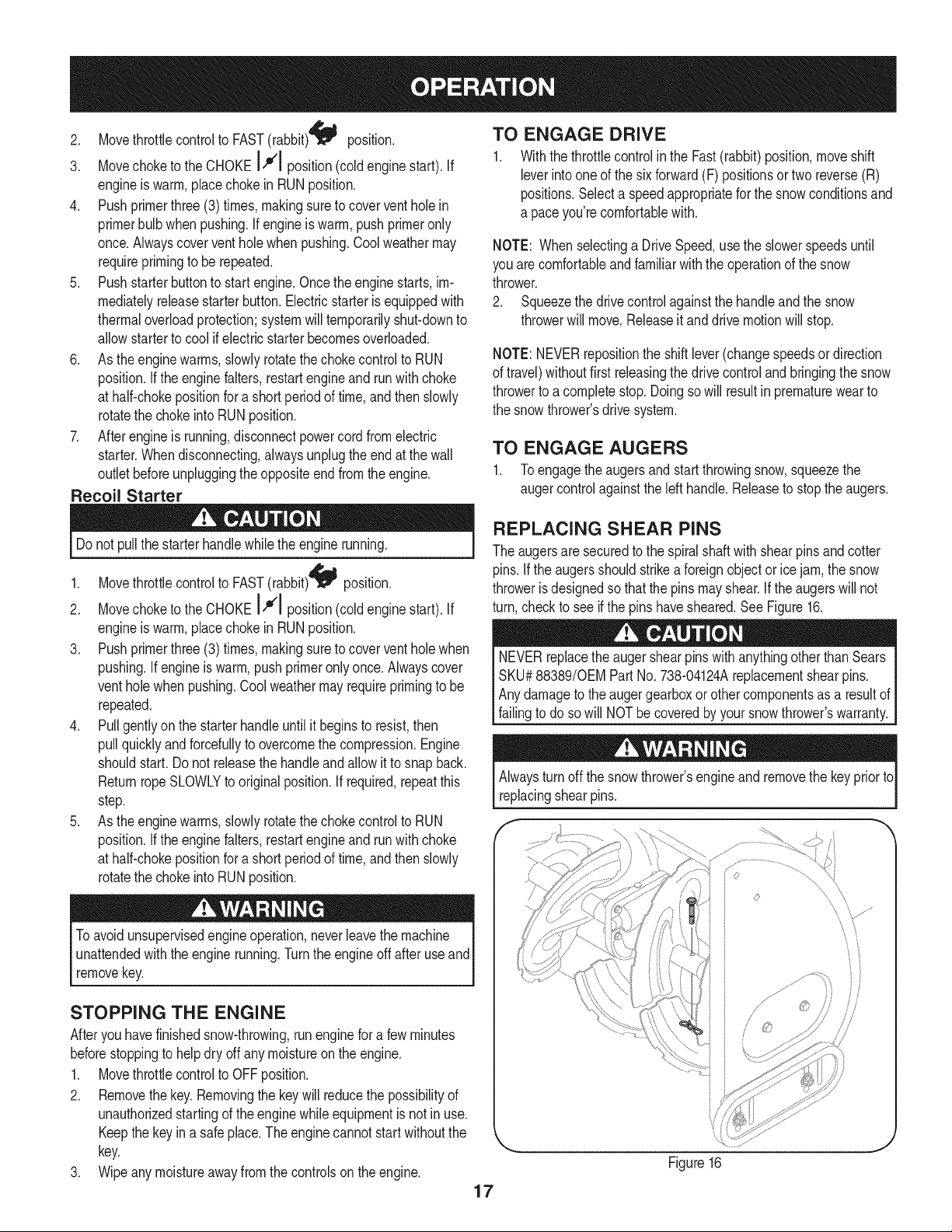
REPLACING SHEAR PiNS
The augersare securedto the spiralshaftwith shearpins andcotter
pins.If the augersshouldstrikea foreignobjectorice jam, the snow
throweris designedso that the pins mayshear.If theaugerswill not
turn,checkto see if the pins havesheared.See Figure16.
NEVERreplacethe augershearpinswithanythingotherthan Sears
SKU#88389/0EM PartNo.738-04124Areplacementshearpins.
Anydamageto theaugergearboxor other componentsas a resultof
failingto do sowill NOTbecoveredbyyour snowthrower'swarranty.
Alwaysturn off thesnowthrower'sengineand removethe key priorto
replacingshearpins.
f "
/
",,,\ _V_¸................
\\
_f
Figure16
MAINTENANCE SCHEDULE
Beforeperforminganytypeofmaintenance/service,disengageall
controlsand stoptheengine.Waituntilallmovingpartshavecometo
acompletestop.Disconnectsparkplugwireandgrounditagainstthe
enginetopreventunintendedstarting.Alwayswearsafetyglassesduring
operationor whileperforminganyadjustmentsor repairs.
EachUseandevery 5
hours
1st5 hours
Annuallyor 25 hours
Annuallyor 50 hours
Annuallyor 100hours
BeforeStorage
1. Engineoil level
2. Looseor missinghardware
3. Unit and engine.
1. Engineoil
1. Sparkplug
2. Controllinkagesand pivots
3. Wheels
4. Gear shaftandAugershaft
1. Engineoil
1. Sparkplug
1. Fuelsystem
Followthe maintenanceschedulegiven below.This chart describes
serviceguidelinesonly.Usethe ServiceLogcolumnto keeptrackof
completedmaintenancetasks.To locate the nearest Sears Service
Centeror to scheduleservice,simplycontactSearsat
1-800-4-MY-HOME®.
1. Check
2. Tightenor replace
3. Clean
1. Change
1. Check
2. Lubewith light oil
3. Lubewith multipurposeautogrease
4. Lubewith light oil
1. Change
1. Change
1. Runengineuntilit stopsfromlack
d fuel
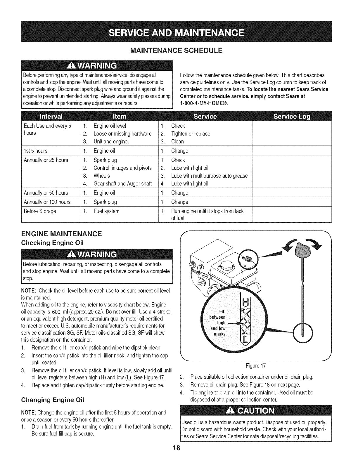
ENGINE MAINTENANCE
Checking Engine Oil
Beforelubricating,repairing,or inspecting,disengageall controls
Iandstop engine.Waituntilall movingpartshavecometo a complete
_stop.
NOTE: Checktheoil levelbeforeeachuseto besurecorrectoil level
is maintained.
Whenaddingoilto the engine,referto viscositychart below.Engine
oilcapacityis 600 ml (approx.20 oz.). Donot over-fill.Usea 4-stroke,
oran equivalenthighdetergent,premiumquality motoroil certified
to meet or exceedU.S.automobilemanufacturer'srequirementsfor
serviceclassificationSG, SR MotoroilsclassifiedSG, SFwill show
thisdesignationon the container.
1. Removethe oil fillercap/dipstickandwipethe dipstickclean.
2. Insertthe cap/dipstickintothe oilfiller neck,andtightenthe cap
until seated.
3. Removethe oil fillercap/dipstick.Iflevelislow, slowlyadd oiluntil
oil levelregistersbetweenhigh(H) andlow (L). SeeFigure17.
4. Replaceand tighten cap/dipstickfirmlybeforestartingengine.
Changing Engine Oil
NOTE:Changethe engineoilafter the first 5 hoursof operationand
oncea seasonorevery50 hoursthereafter.
1. Drainfuelfrom tank by runningengineuntilthe fuel tank isempty.
Besurefuel fill cap is secure.
J
Figure17
2. Placesuitableoil collectioncontainerunderoil drainplug.
3. Removeoil drainplug.SeeFigure18on nextpage.
4. Tip engineto drain oil intothe container.Usedoil mustbe
disposedof at a propercollectioncenter.
Usedoil isa hazardouswasteproduct.Disposeof usedoil properly.
IDo notdiscardwith householdwaste.Checkwithyour localauthori-
lties or SearsServiceCenterfor safe disposal/recyclingfacilities.
18
.
6.
Reinstallthe drainplugand tightenit securely.
Refillwiththe recommendedoil andcheckthe oil level.See
RecommendedOil Usagechart.Theengine'soil capacityis 20
ounces.
, ,
[
(%-40 °-20 o 0o 200 400
("c) -300 -200 -10° 0°
DO NOTuse nondetergentoilor 2-strokeengineoil. Itcould shorten
the engine'sservicelife.
Oil Drain
Plug
7. Reinstallthe oil fillercap/dipsticksecurely.
Figure18
Thoroughlywashyour handswithsoap andwateras soonas
possibleafterhandling usedoil.
Checking Spark Plug
DO NOTcheckfor sparkwithspark plug removed.DO NOTcrank
enginewith sparkplug removed.
Ifthe enginehas been running,the mufflerwill be very hot.Be careful
notto touch the muffler.
NOTE: Checkthe sparkplug oncea seasonorevery 25 hoursof
operation.Changethe sparkplugoncea seasonor every100hours.
Toensureproperengineoperation,the sparkplugmustbe properly
gappedandfreeof deposits.
1. Removethesparkplug bootand use a sparkplugwrenchto
removethe plug.See Figure19.
2. Visuallyinspectthe spark plug.Discardthe spark plugif thereis
apparentwear,or if the insulatoris crackedor chipped.Cleanthe
sparkplugwith a wirebrush if it is to be reused.
3. Measurethe pluggap with a feelergauge.Correctas necessary
by bendingsideelectrode.SeeFigure20. Thegap shouldbe set
to .02-.03inches(0.60-0.80ram).
4. Checkthatthe sparkplug washeris ingood conditionandthread
the sparkplug in by handto preventcross-threading.
5. After thespark plugis seated,tightenwitha sparkplugwrenchto
compressthe washer.
NOTE:Wheninstallinga newsparkplug,tighten1/2-turnafter the
sparkplugseatsto compressthe washer.Whenreinstallinga used
sparkplug,tighten1/8-to 1/4-turnafter the sparkplugseatsto
compressthe washer.
19
Spark Plug
O
J
SparkPlug Boot
Figure19
Electrode
.02=.03 in.
(0.60-0.80 ram)
Figure20
hotandcan ine.
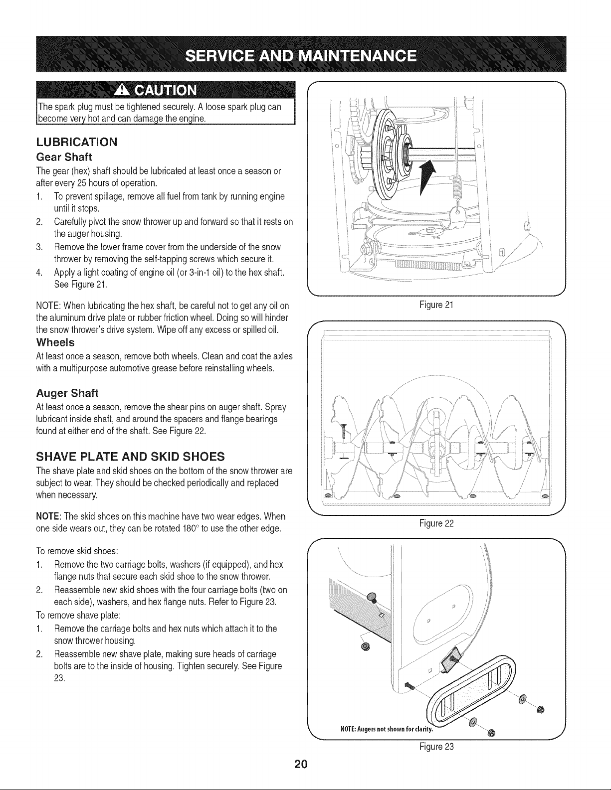
LUBRICATION
Gear Shaft
Thegear(hex)shaft shouldbe lubricatedat least oncea seasonor
afterevery25 hoursof operation.
1. Topreventspillage,removeall fuel fromtank by runningengine
until it stops.
2. Carefullypivotthe snowthrowerup and forwardso that it restson
theaugerhousing.
3. Removethe lowerframecover fromthe undersideof the snow
throwerby removingthe self-tappingscrewswhich secureit.
4. Applya lightcoatingof engineoil (or3-in-1oil) to the hexshaft.
SeeFigure21.
NOTE:Whenlubricatingthe hexshaft,be carefulnotto get any oil on
thealuminumdriveplateor rubberfrictionwheel.Doingsowill hinder
the snowthrower'sdrive system.Wipeoff anyexcessor spilledoil.
Wheels
At least oncea season,removebothwheels.Cleanand coat theaxles
witha multipurposeautomotivegreasebeforereinstallingwheels.
Auger Shaft
At least oncea season,removethe shearpinson augershaft.Spray
lubricantinsideshaft,andaroundthe spacersand flangebearings
foundat eitherend of the shaft.SeeFigure22.
SHAVE PLATE AND SKID SHOES
The shaveplateand skidshoesonthe bottomof the snowthrowerare
subjectto wear.Theyshouldbe checkedperiodicallyandreplaced
whennecessary.
NOTE:Theskidshoeson thismachinehavetwowearedges.When
onesidewears out, theycan be rotated1800to usethe otheredge.
To removeskid shoes:
1. Removethe two carriagebolts,washers(if equipped),andhex
flangenutsthat secureeach skidshoeto the snowthrower.
2. Reassemblenew skidshoeswith the fourcarriagebolts (two on
eachside),washers,and hex flangenuts.Referto Figure23.
To removeshaveplate:
1. Removethe carriageboltsand hexnutswhichattachit to the
snowthrowerhousing.
2. Reassemblenew shaveplate,makingsureheadsof carriage
boltsare to the insideof housing.Tightensecurely.SeeFigure
23.
o i
)
// "?X
/ .... )
{;:7/
7/' ................
Figure21
/
i
f
Figure22
J
Figure23
2O
ADJUSTMENTS
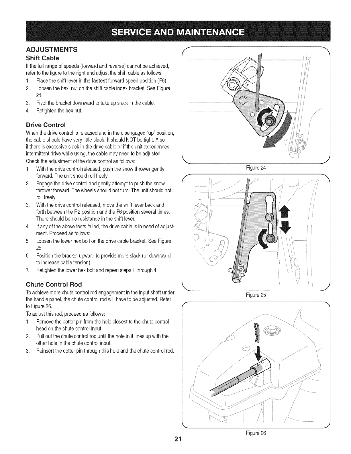
Shift Cable
If thefull rangeof speeds(forwardandreverse)cannotbe achieved,
referto the figureto the rightandadjustthe shift cableas follows:
1. Placethe shiftleverin thefastest forwardspeedposition(F6).
2. Loosenthe hex nuton the shiftcable indexbracket.See Figure
24.
3. Pivotthe bracketdownwardto takeup slack inthe cable.
4. Retightenthehex nut.
Drive Control
Whenthedrivecontrolis releasedand in thedisengaged"up"position,
the cableshouldhaveverylittle slack.It shouldNOTbetight. Also,
if thereis excessiveslackin thedrive cableor if the unitexperiences
intermittentdrivewhileusing,the cable mayneed to beadjusted.
Checktheadjustmentof the drivecontrolas follows:
1. Withthedrivecontrolreleased,pushthe snowthrowergently
forward.The unitshouldrollfreely.
2. Engagethe drivecontrolandgently attemptto pushthe snow
throwerforward.Thewheelsshouldnotturn.The unitshouldnot
rollfreely.
3. With thedrivecontrol released,movethe shift leverbackand
forthbetweenthe R2positionand the F6 positionseveraltimes.
Thereshouldbeno resistancein the shiftlever.
4. If anyof the abovetests failed,the drivecable is in needof adjust-
ment.Proceedas follows:
5. Loosenthe lowerhexbolt onthe drivecable bracket.See Figure
25.
6. Positionthe bracketupwardto providemoreslack(or downward
to increasecabletension).
7. Retightenthe lowerhex boltand repeatsteps1 through4.
Chute Control Rod
Toachievemorechutecontrolrodengagementin the input shaftunder
the handlepanel,the chute controlrodwill haveto beadjusted.Refer
to Figure26.
Toadjustthis rod,proceedas follows:
1. Removethecotterpin fromthe holeclosestto the chute control
headon thechutecontrolinput.
2. Pull outthe chutecontrolrod untilthe holein it lines upwith the
otherholein the chutecontrolinput.
3. Reinsertthe cotterpin throughthis holeandthechutecontrolrod.
f
.........
Figure25
J
\
\
/
/ ,
J
J
Figure26
21
Auger Control f "_
Referto the Assemblysectionfor instructionsonadjustingtheauger
controlcable. _'
Skid Shoes
Referto the Assemblysectionfor instructionsonadjustingthe skid
shoes.
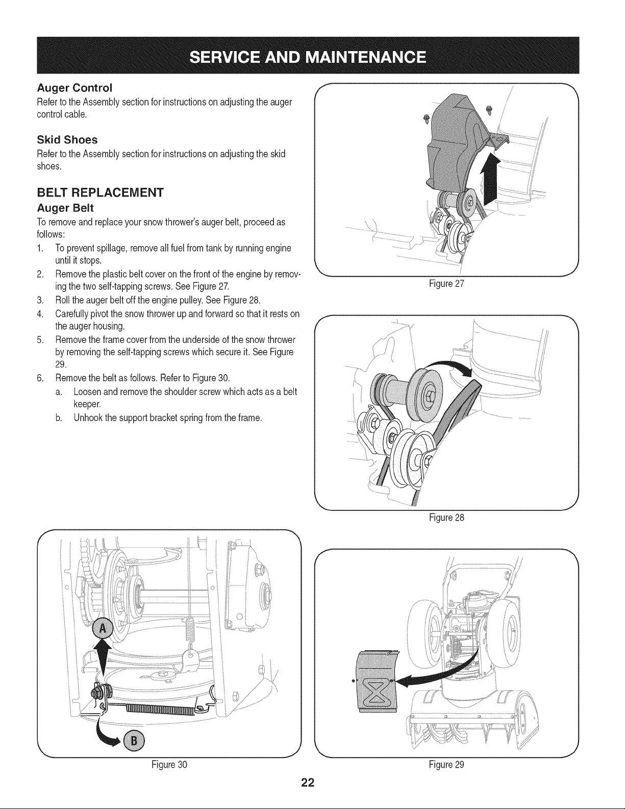
BELT REPLACEMENT
Auger Belt
To removeand replaceyoursnowthrower'saugerbelt, proceedas
follows:
1. Topreventspillage,removeall fuel fromtank by runningengine
until itstops.
2. Removethe plasticbelt coveronthe frontof the engineby remov-
ingthe twoself-tappingscrews.See Figure27.
3. Rollthe augerbeltoff theenginepulley.See Figure28.
4. Carefullypivotthe snowthrowerup and forwardso that itrestson
theauger housing.
5. Removethe frame coverfrom the undersideof the snow thrower
by removingthe self-tappingscrewswhich secureit. SeeFigure
29.
6. Removethe beltas follows.Referto Figure30.
a. Loosenand removethe shoulderscrewwhichactsas a belt
keeper.
b. Unhookthe supportbracketspringfromthe frame.
Figure27
J
f
Figure28
J
f
Figure30 Figure29
J
7. Removethebeltfromaroundtheaugerpulley,andslipthebelt
betweenthesupportbracketandtheaugerpulley.SeeFigure31.
8. Reassembleaugerbeltbyfollowingtheseinstructionsinopposite
orderandmannerofremoval.
9. PerformtheAugerControltestoutlinedintheAssemblysection
ofthismanual.
NOTE:DoNOTforgettoreinstalltheshoulderscrewandreconnect
thespringtotheframeafterinstallingareplacementaugerbelt.
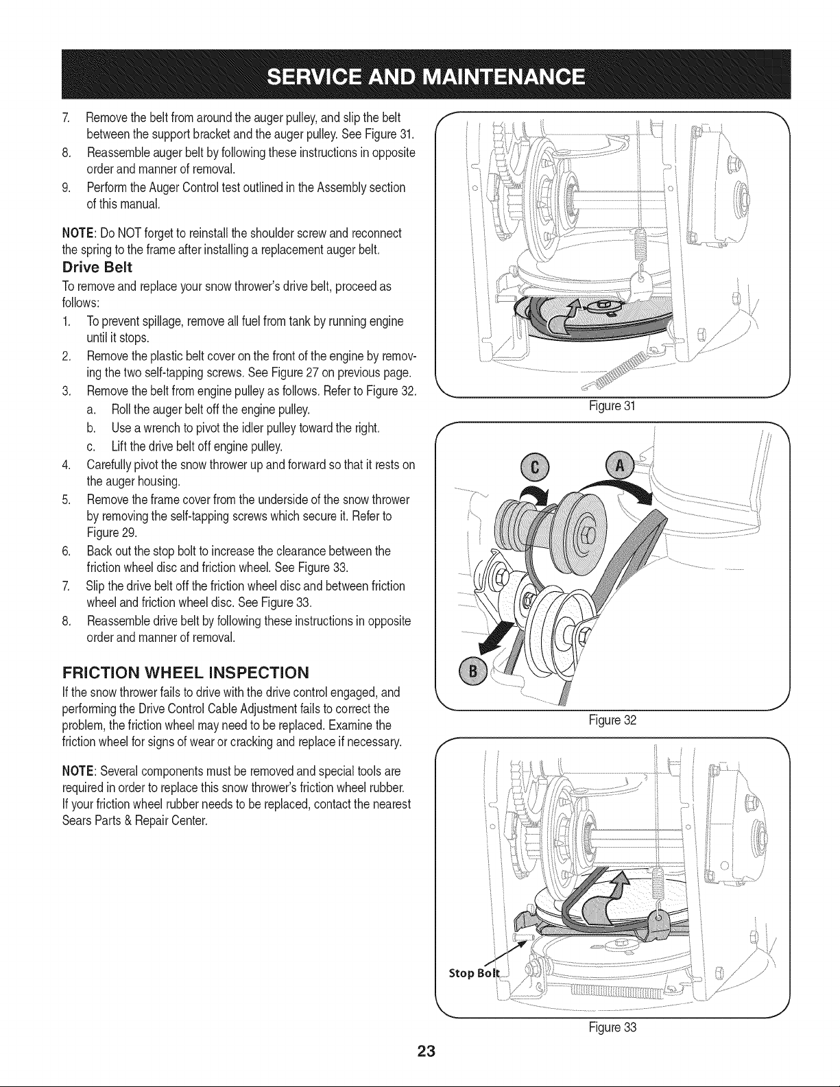
Drive Belt
Toremoveand replaceyoursnow thrower'sdrivebelt, proceedas
follows:
1. Topreventspillage,removeallfuel fromtank by runningengine
untilit stops.
2. Removetheplasticbelt coveronthe front of the engineby remov-
ingthe twoself-tappingscrews.See Figure27on previouspage.
3. Removethebelt from enginepulleyas follows. Referto Figure32.
a. Rollthe augerbeltoff theenginepulley.
b. Use a wrenchto pivotthe idlerpulleytowardthe right.
c. Liftthe drivebelt off enginepulley.
4. Carefullypivotthe snowthrowerup and forwardsothat itrestson
the augerhousing.
5. Removetheframecoverfrom the undersideof the snowthrower
by removingthe self-tappingscrewswhich secureit. Referto
Figure29.
6. Back outthe stopbolt to increasethe clearancebetweenthe
frictionwheeldisc and frictionwheel.See Figure33.
7. Slipthe drivebelt offthe frictionwheeldisc and betweenfriction
wheeland frictionwheeldisc.See Figure33.
8. Reassembledrive beltby followingtheseinstructionsin opposite
orderand mannerof removal.
FRICTION WHEEL INSPECTION
If the snowthrowerfailsto drivewith thedrivecontrolengaged,and
performingthe DriveControlCableAdjustmentfails to correctthe
problem,the frictionwheelmay needto be replaced.Examinethe
frictionwheelfor signsof wearor crackingand replaceif necessary.
NOTE:Severalcomponentsmustbe removedandspecialtools are
requiredinorder to replacethis snowthrower'sfrictionwheelrubber.
If yourfrictionwheel rubberneedsto be replaced,contact the nearest
SearsParts& RepairCenter.
iO i
Figure31
f
Figure32
J
Stop Bol
Figure33
23
Ifthe snowthrowerwillnot be usedfor30 daysor longer,or if it is the endof the snowseasonwhenthe lastpossibilityof snowis gone,the
equipmentneedsto bestoredproperly.Followstorageinstructionsbelowto ensuretop performancefrom the snowthrowerfor manymoreyears.
PREPARING ENGINE
Enginesstoredover30 daysneedto be drainedof fuel to prevent
deteriorationandgumfrom formingin fuel systemor onessential
carburetorparts.If thegasolineinyourenginedeterioratesduring
storage,youmay needto havethe carburetor,and otherfuel system
components,servicedor replaced.
1. Removeall fuel fromtank by runningengineuntil it stops.Donot
attemptto pourfuel fromthe engine.
2. Changethe engineoil.
3. Removesparkplugand pour approximately1 oz. (30 rnl)of clean
engineoil intothe cylinder.Pullthe recoilstarterseveraltimesto
distributetheoil, and reinstallthe sparkplug.
4. Cleandebrisfromaroundengine,and under,around,and behind
muffler.Applya lightfilm of oilon anyareasthatare susceptible
to rust.
• Storein a clean,dry andwellventilatedarea awayfrom anyap-
pliancethat operateswithaflameor pilotlight,suchas a furnace,
waterheater,or clothesdryer.Avoidany areawitha spark
producingelectricmotor,or wherepowertools are operated.
Neverstoresnowthrowerwith fuel intank indoorsor inpoorlyventi-
latedareas,wherefuel fumesmay reachan openflame,sparkor pilol
lightas ona furnace,waterheater,clothesdryer orgas appliance.
• If possible,avoidstorageareaswith high humidity.
• Keepthe enginelevelin storage.Tiltingcan causefuel oroil
leakage.
PREPARING SNOW THROWER
Whenstoringthe snowthrowerin anunventilatedormetal stor-
age shed,careshouldbetakento rustprooftheequipment.Using
a light oilor silicone,coat theequipment,especiallyanychains,
springs,bearingsandcables.
• Removealldirt fromexteriorof engineand equipment.
• Followlubricationrecommendations.
• Storeequipmentin a clean,dry area.
24
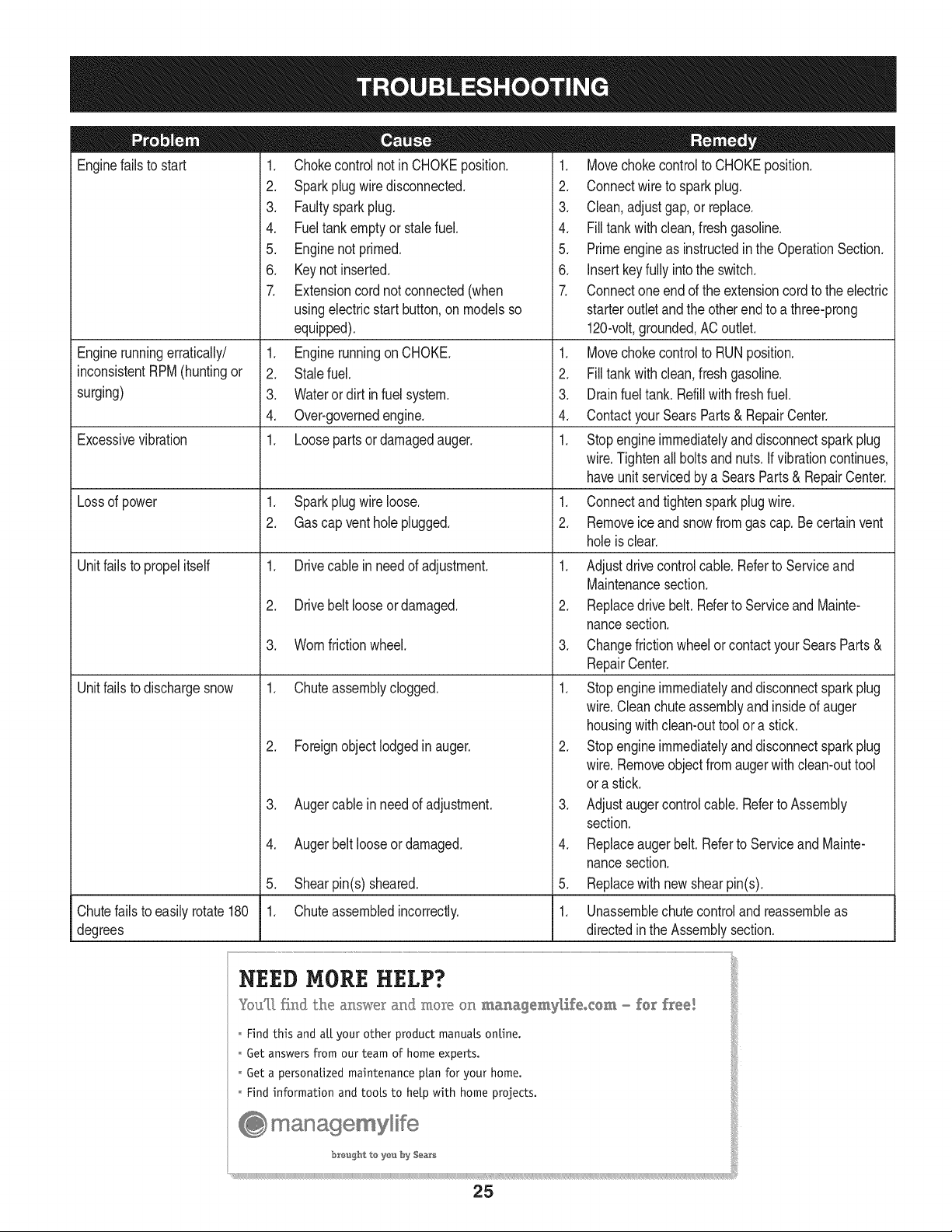
Enginefailsto start
Enginerunningerratically/
inconsistentRPM(huntingor
surging)
Excessivevibration
Lossof power
Unitfailsto propelitself
Unitfailsto dischargesnow
1. Chokecontrolnot inCHOKEposition.
2. Sparkplugwire disconnected.
3. Faultysparkplug.
4. Fueltank emptyor stalefuel.
5. Enginenot primed.
6. Keynot inserted.
7. Extensioncordnot connected(when
usingelectricstartbutton,on modelsso
equipped).
1. Enginerunningon CHOKE.
2. Stalefuel.
3. Wateror dirt in fuel system.
4. Over-governedengine.
1. Loosepartsor damagedauger.
1. Sparkplugwire loose.
2. Gascap venthole plugged.
1. Drivecable inneed of adjustment.
2. Drivebelt looseor damaged.
3. Wornfrictionwheel.
1. Chuteassemblyclogged.
2. Foreignobjectlodgedin auger.
3. Augercablein needof adjustment.
4. Augerbelt looseordamaged.
5. Shearpin(s) sheared.
1. Chuteassembledincorrectly.
1. Movechokecontrolto CHOKEposition.
2. Connectwireto sparkplug.
3. Clean,adjustgap,or replace.
4. Filltank with clean,freshgasoline.
5. Primeengineas instructedinthe OperationSection.
6. Insertkeyfully intothe switch.
7. Connectoneend of the extensioncordto the electric
starteroutletand the otherendto a three-prong
120-volt,grounded,ACoutlet.
1. Movechokecontrolto RUNposition.
2. Filltank with clean,freshgasoline.
3. Drainfueltank. Refillwithfreshfuel.
4. ContactyourSearsParts & RepairCenter.
1. Stopengineimmediatelyand disconnectsparkplug
wire.Tightenall boltsand nuts.If vibrationcontinues,
haveunit servicedbya SearsParts& RepairCenter.
1. Connectandtightenspark plugwire.
2. Removeiceand snowfromgascap. Becertainvent
holeis clear.
1. Adjustdrivecontrolcable. Referto Serviceand
Maintenancesection.
2. Replacedrive belt.Referto Serviceand Mainte-
nancesection.
3. Changefrictionwheelor contactyour SearsParts&
RepairCenter.
1. Stopengineimmediatelyand disconnectsparkplug
wire.Cleanchute assemblyand insideof auger
housingwith clean-outtoolor a stick.
2. Stopengineimmediatelyand disconnectsparkplug
wire.Removeobjectfromaugerwith clean-outtool
ora stick.
3. Adjustaugercontrolcable. Referto Assembly
section.
4. Replaceauger belt. Referto Serviceand Mainte-
nancesection.
5. Replacewith newshearpin(s).
Chutefailsto easilyrotate180 1. Unassemblechute controland reassembleas
degrees directedinthe Assemblysection.
NEED MORE HELP?
YouT[ fk@ the al_swe_:and moR÷ on _a_agemyl,ifeocem _ fo_ flee!
o Hnd this and aLLyour other product manuals online.
o Get answers from our team of home experts.
Get a personalized maintenance plan for your home.
Find information and tools to help with home projects.
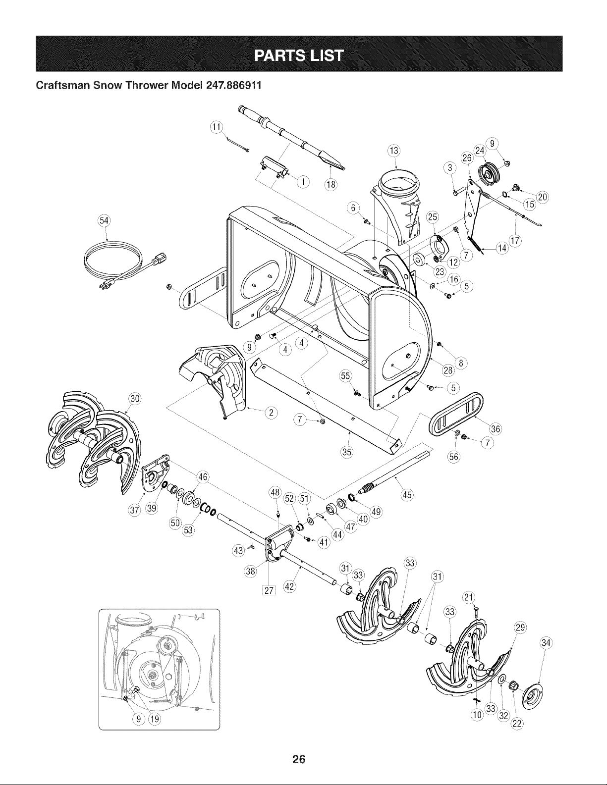
Craftsman Snow Thrower Model 247.886911
26
Craftsman Snow Thrower IViodel 247.886911
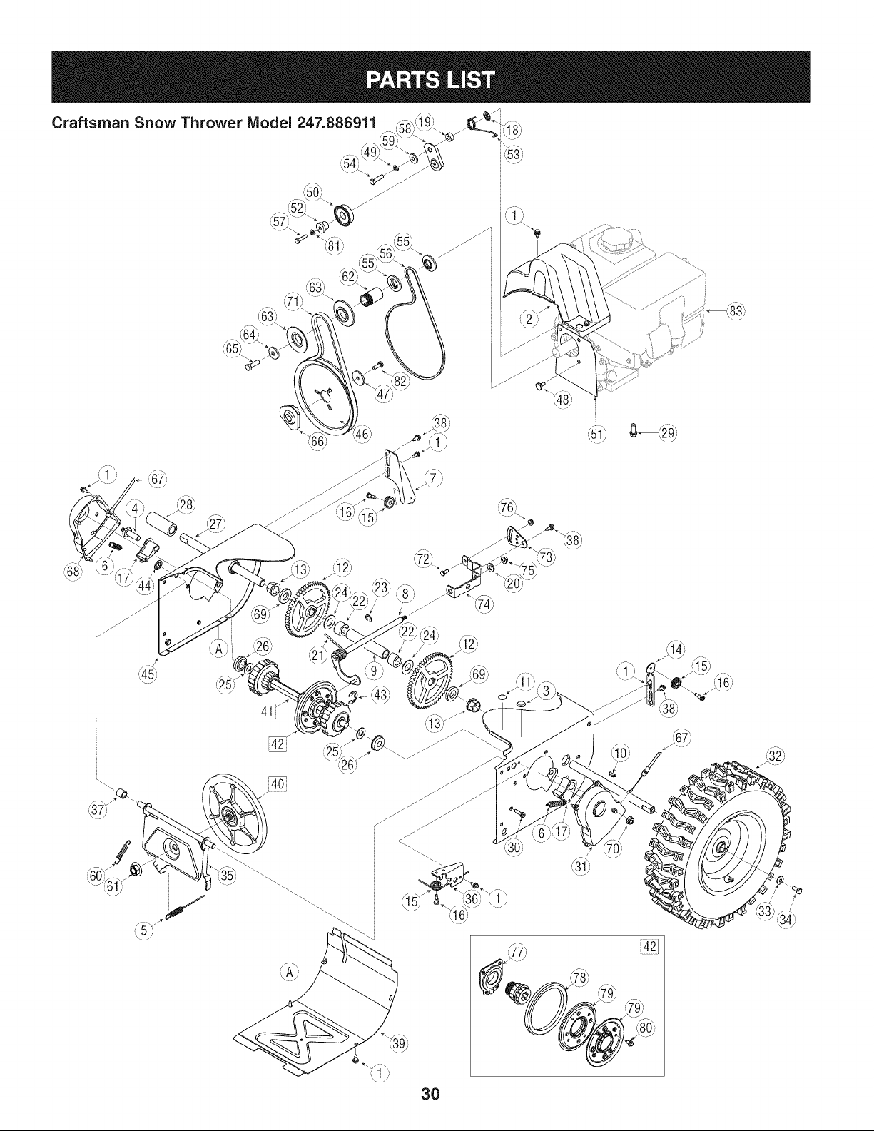
D = 0 0
731-2635 SnowRemovalToolMount
2. 684-04057A-0637 ImpellerAssembly,12"Dia.
3. L710-0347 LHex Screw,3/8-16,1.75,Gr5
4. 710-0451 Bolt,Carriage,5/16-18,.750Grl
5. 710-04484 Screw, 5/16-18,0.750
6. 710-0703 Screw,Carriage,1/4-20,.750,Gr5
7. 712-04063 Nut, FlangeLock,5/16-18,Nylon
8. 712-04064 Nut, FlangeLock,1/4-20,Nylon
9. 712-04065 Nut, FlangeLock,3/8-16,Nylon
10. 714-04040 CotterPin,Bow-tie
11. 725-0157 Cable,Tie, 3/16x .05x 7.4
12. 926-04012 Nut, Push-on,.25 Dia
13. 731-07525 Chute,Adapter5" Dia
14. 732-04460 Spring,Extension,.38OD x 4.59
15. 736-0174 Washer,Wave,.625x .885x .015
16. 736-0242 Washer,Bell, .340x .872x .060
17. 746-04230 ClutchCable,Auger,47.23"
18. 931-2643 SnowRemovalTool
19. .738-0143 J Screw,Shoulder,.498x .34,3/8-16
20. 938-0281 Screw,Shoulder,.625x .17,3/8-16
21. 738-04124A ShearPin, .25x 1.50
22. 941-0245 Bearing,HexFlangex .75ID
23. 941-0309 Bearing,Ball,.75 ID x 1.85OD
24. 756-04224 Flat Pulley,Idler, 2.75OD
25. 790-00075 Housing,Bearing,1.85ID
26. 790-00080A-0637 Bracket,Auger Idlerw/ Brake
27. J 918-04172B J GearboxAssembly,Auger,26"
28. 684-04264-0721 HousingAssembly,Auger26"
D = O O
SpiralAssembly,LH
30. SpiralAssembly,RH
31. Spacer,1.25OD x .75ID x 1.00
32. Washer,Flat,.76x 1.49x .06
33. Bushing,Flange,.80ID x .91OD
34. Housing,1"HexBearing
684-04107-0637
684-04108-0637
731-04870
736-0188
741-0493A
790-00087A-0637
35. 790-00121-0721
36. 731-05984A
37. 918-0123A
38. 918-0124A
39. 921-0338
40. 741-0662
41. 710-0642
42. 711-04284
ShavePlate,2.25 x 25.66
SlideShoe
Housing,Auger,RH Reduced
Housing,Auger,LH Reduced
Seal,Oil, .750x 1.00x .125
Bearing,Flange,.75x 1.0x .59
Screw,Self-tapping,1/4-20,0.750
Axle,Auger,26"
43. 914-0161 Key,Hi-pro3/16x 5/8
44. 715-04021 Pin, Dowel,.25 ODx 1.2
45. 917-04126 Shaft,Worm .75OD
46. 717-04861 Gear,Worm20T
47. 718-04071 Collar,Thrust
48. 721-0325 Plug, 1/4x .437
49. 721-0327 Seal,Oil, .75x 1 x .131
50. 936-0351 Washer,Flat,.760ID x 1.50D
51. 736-3084 Washer,Flat,.51x 1.12
52. 741-0663 Bearing,Flange,.75x 1.0x .925
53. 741-0661A Bearing,Flange,.75x 1.00x .975
54. 929-0071A ExtensionCord,110V
55. 710-0276 Screw,Carriage,5/16-18x 1.00
56. 936-0159 Washer,Fiat,.349x .879x .063
27
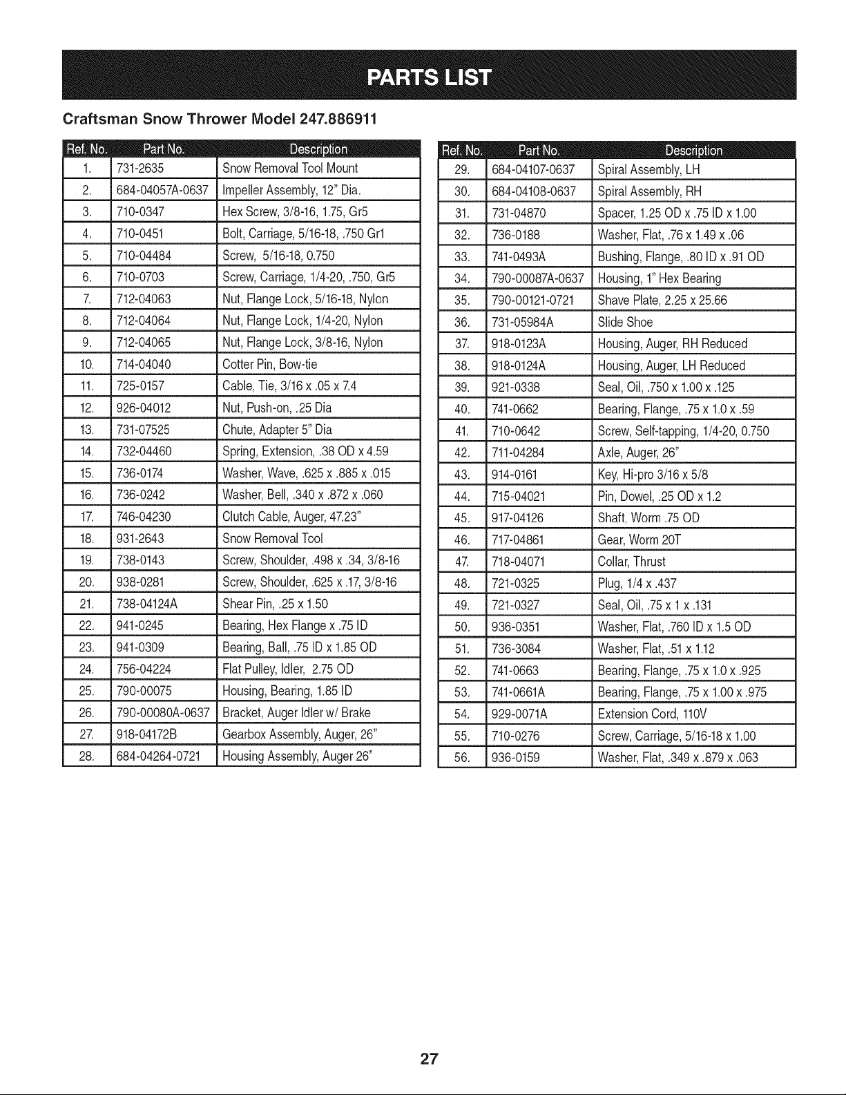
Craftsman Snow Thrower IViodel 247.886911
28
i
['_.
_..................................;;.................7!+:....................._7.................
7
[]
Craftsman Snow Thrower IViodel 247.886911
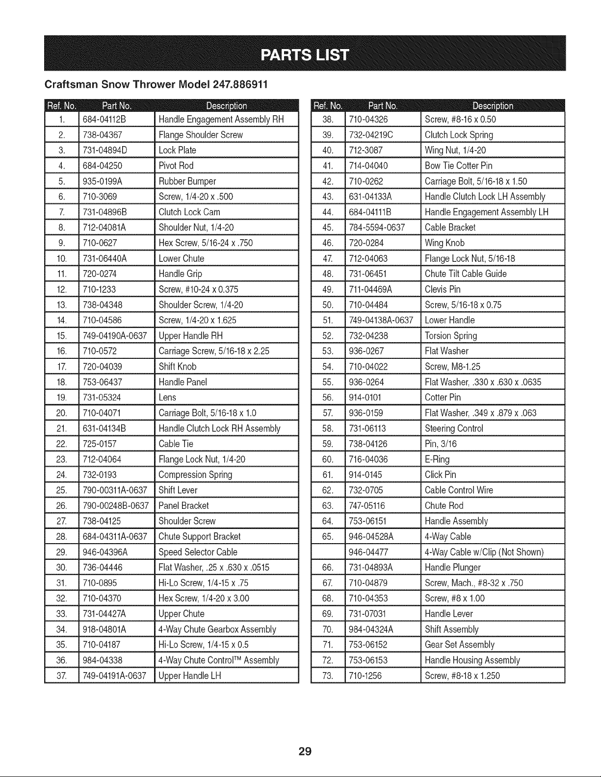
684-04112B HandleEngagementAssemblyRH
2. 738-04367 FlangeShoulderScrew
3. 731-04894D LockPlate
4. 684-04250 PivotRod
5. 935-0199A RubberBumper
6. 710-3069 Screw,1/4-20x .500
7. 731-04896B ClutchLock Cam
8. 712-04081A ShoulderNut, 1/4-20
9. 710-0627 HexScrew,5/16-24x .750
10. 731-06440A LowerChute
11. 720-0274 HandleGrip
12.
710-1233 Screw,#10-24x 0.375
13. 738-04348 ShoulderScrew,1/4-20
14. 710-04586 Screw,1/4-20x 1.625
15. 749-04190A-0637 UpperHandleRH
16. 710-0572 CarriageScrew,5/16-18x 2.25
17. 720-04039 Shift Knob
18. 753-06437 HandlePanel
19. 731-05324 Lens
20. 710-04071 CarriageBolt,5/16-18x 1.0
21. 631-04134B HandleClutchLockRHAssembly
22. 725-0157 CableTie
23. 712-04064 FlangeLockNut, 1/4-20
24. 732-0193 CompressionSpring
25. 790-00311A-0637 Shift Lever
26. 790-00248B-0637 PanelBracket
27. 738-04125 ShoulderScrew
28. 684-04311A-0637
29. 946-04396A
30. 736-04446
31. 710-0895
32. 710-04370
33. 731-04427A
34. 918-04801A
35. 710-04187
36. 984-04338
3_ 749-04191A-0637
ChuteSupportBracket
SpeedSelectorCable
FiatWasher,.25x .630x .0515
Hi-LoScrew,1/4-15x .75
HexScrew,1/4-20x 3.00
UpperChute
4-WayChuteGearboxAssembly
Hi-LoScrew,1/4-15x 0.5
4-WayChuteControlTM Assembly
UpperHandleLH
D = W O
710-04326 Screw,#8-16x 0.50
39. 732-04219C ClutchLock Spring
40. 712-3087 Wing Nut, 1/4-20
41. 714-04040
42. 710-0262
43. 631-04133A
44. 684-04111B
45. 784-5594-0637
46. 720-0284
4_ 712-04063
48. 731-06451
BowTie CotterPin
CarriageBolt,5/16-18x 1.50
HandleClutchLock LHAssembly
HandleEngagementAssemblyLH
Cable Bracket
Wing Knob
FlangeLock Nut,5/16-18
ChuteTilt CableGuide
49. 711-04469A ClevisPin
50. 710-04484 Screw,5/16-18x 0.75
51. 749-04138A-0637 LowerHandle
52. 732-04238 TorsionSpring
53. 936-0267 FiatWasher
54. 710-04022 Screw,M8-1.25
55. 936-0264 FiatWasher,.330x .630x .0635
56. 914-0101 CotterPin
57. 936-0159 FiatWasher,.349x .879x .063
58. 731-06113 SteeringControl
59. 738-04126 Pin,3/16
60. 716-04036 E-Ring
61. 914-0145 Click Pin
62. 732-0705 CableControlWire
63. 747-05116 Chute Rod
64. 753-06151 HandleAssembly
65. 946-04528A 4-WayCable
946-04477 4-WayCablew/Clip (NotShown)
66. 731-04893A HandlePlunger
67. 710-04879 Screw,Mach.,#8-32 x .750
68. 710-04353 Screw,#8 x 1.00
69. 731-07031 HandleLever
70. 984-04324A ShiftAssembly
71. 753-06152 Gear SetAssembly
72. 753-06153 HandleHousingAssembly
73. 710-1256 Screw,#8-18x 1.250
29
Craftsman Snow Thrower IViodel 247.886911 _dJ_' _ i_o_
F__\\'_v/_"_/'_ i"_
42_
i4o;
/
3O
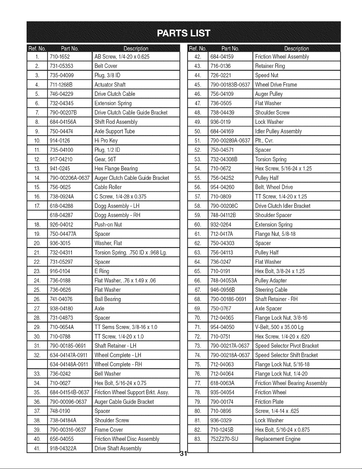
D_ i B O ¸
710-1652 AB Screw,1/4-20x 0.625
2. 731-05353 BeltCover
3. 735-04099 Plug,3/8 ID
4. 711-1268B ActuatorShaft
5. 746-04229 DriveClutchCable
6. 732-04345 ExtensionSpring
7. 790-00207B DriveClutchCableGuideBracket
8. 684-04156A ShiftRodAssembly
9. 750-04474 AxleSupportTube
10. 914-0126 Hi Pro Key
11. 735-04100 Plug,1/2 ID
12. 917-04210 Gear,56T
13. 941-0245 HexFlangeBearing
14. 790-00206A-0637 AugerClutchCableGuideBracket
15. 756-0625 CableRoller
16. 738-0924A C Screw,1/4-28x 0.375
17. 618-04288 DoggAssembly-LH
618-04287 DoggAssembly- RH
18. 926-04012 Push-onNut
19. 750-04477A Spacer
20. 936-3015 Washer,Fiat
21. 732-04311 TorsionSpring,.750IDx .968 Lg.
22. 731-05297 Spacer
23. 916-0104 E Ring
24. 736-0188 FiatWasher,.76x 1.49x .06
25. 736-0626 FiatWasher
26. 741-04076 BallBearing
27. 938-04180 Axle
28. 731-04873 Spacer
29. 710-0654A TT SeresScrew,3/8-16x 1.0
30. 710-0788 TT Screw,1/4-20x 1.0
31. 790-00185-0691 Shaft Retainer- LH
32. 634-04147A-0911 WheelComplete-LH
634-04148A-0911 WheelComplete-RH
33. 736-0242
34. 710-0627
35. 684-04154B-0637
36. 790-00096-0637
3_ 748-0190
38. 738-04184A
39. 790-00316-0637
40. 656-04055
41. 918-04322A
BellWasher
HexBolt,5/16-24x 0.75
FrictionWheelSupportBrkt.Assy.
AugerCableGuide Bracket
Spacer
ShoulderScrew
FrameCover
FrictionWheelDiscAssembly
DriveShaftAssembly
31
m _ O
684-04159 FrictionWheelAssembly
43. 716-0136 RetainerRing
44. 726-0221 SpeedNut
45. 790-00183B-0637 WheelDrive Frame
46. 756-04109 AugerPulley
47. 736-0505 FiatWasher
48. 738-04439 ShoulderScrew
49. 936-0119 LockWasher
50. 684-04169 IdlerPulleyAssembly
51. 790-00289A-0637 Pit.,Cvr.
52. 750-04571 Spacer
53. 732-04308B TorsionSpring
54. 710-0672 HexScrew,5/16-24x 1.25
55. 756-04252 PulleyHalf
56. 954-04260 Belt,WheelDrive
57. 710-0809 TT Screw,1/4-20x 1.25
58. 790-00208C DriveClutchIdlerBracket
59. 748-04112B ShoulderSpacer
60. 932-0264 ExtensionSpring
61. 712-0417A FlangeNut,5/8-18
62. 750-04303 Spacer
63. 756-04113 PulleyHalf
64. 736-0247 FiatWasher
65. 710-0191 HexBolt,3/8-24x 1.25
66. 748-04053A PulleyAdapter
67. 946-0956B SteeringCable
68. 790-00186-0691 ShaftRetainer- RH
69. 750-0767 Axle Spacer
70. 712-04065 FlangeLockNut,3/8-16
71. 954-04050 V-Belt,.500x 35.00 Lg
72. 710-0751 HexScrew,1/4-20x .620
73. 790-00217A-0637 SpeedSelectorPivotBracket
74. 790-00218A-0637 SpeedSelectorShiftBracket
75. 712-04063 FlangeLockNut,5/16-18
76. 712-04064 FlangeLockNut, 1/4-20
77. 618-0063A FrictionWheelBearingAssembly
78. 935-04054 FrictionWheel
79. 790-00174 FrictionPlate
80. 710-0896 Screw,1/4-14x .625
81. 936-0329 LockWasher
82. 710-1245B HexBolt,5/16-24x 0.875
83. 752Z270-SU ReplacementEngine
Craftsman Engine IViodel 270-SU For Snow Thrower IViodel 247.886911
84
26
\
23
26 84 56 70
\_ 27 78
126 125
!L-J
121
I
2_128
1 1
i /
11
\
1815
32
\
26 26
32
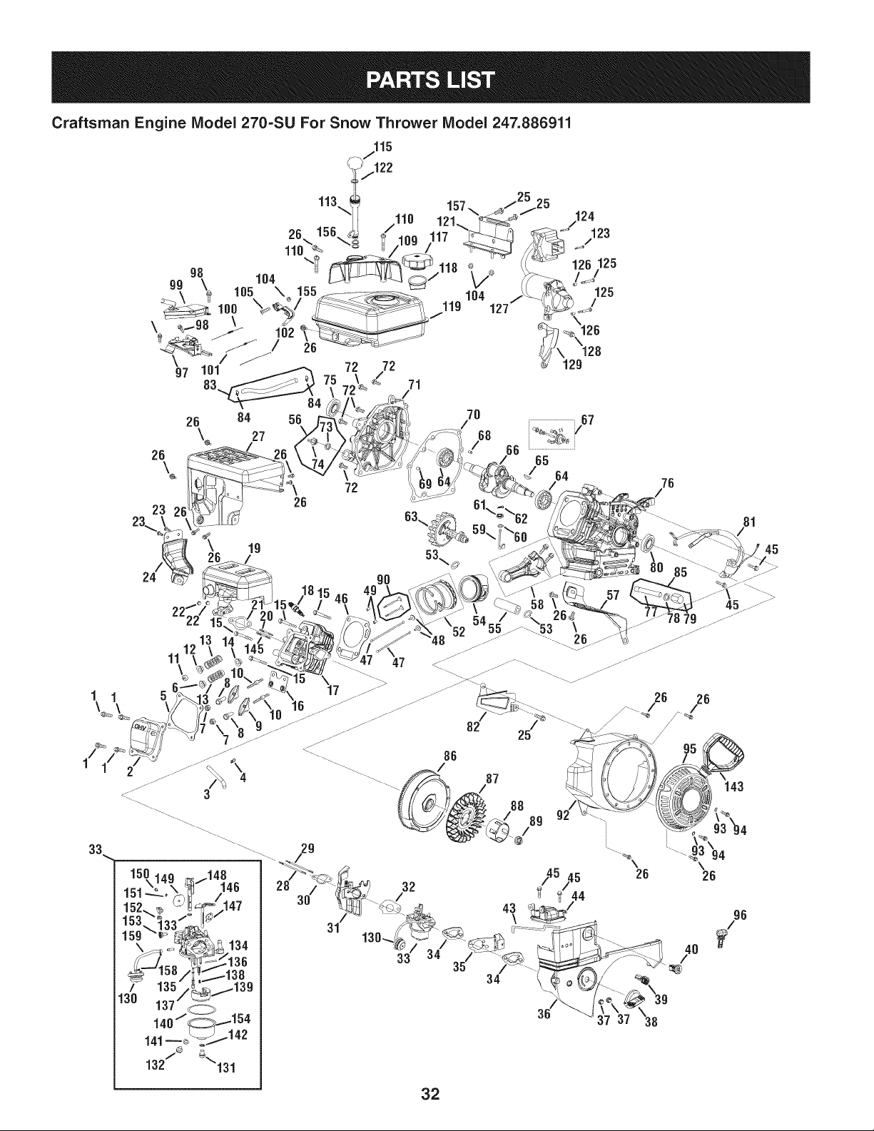
Craftsman Engine IViodel 270=SU For Snow Thrower IViodel 247.886911
m
1
2
3
4
7
8
10
15
18
19
20
21
22
23
24
25
26
27
28
29
33
35
36
37
38
39
40
43
44
45
47
49
57
59
60
62
64
65
68
69
710-04968
951-11054
731-07059
726-04101
751-11124
751-11123
710-04902
710-04933
951-10292
951-11282
710-05001
951-11289
712-04214
710-04914
951-11111
710-04940
710-04915
951-10642A
710-04939
710-04910
951-10638A
951-11112
951-10634
712-04213
951-11284
951-10757
951-10637
951-10640
951-10635
710-04919
951-10648
715-04090
951-11113
951-11356
736-04461
714-04074
951-11369
951-10307
715-04092
715-04096
D = I! O
Bolt
ValveCover
BreatherHose
HoseClamp
PivotLockingNut
ValveAdjustingNut
PivotBolt
Bolt
SparkPlug
MufflerAssembly
Stud
MufflerGasket
Nut
Bolt
ExhaustPipe Shield
Bolt
Bolt
MufflerShroud
Stud,M6x117
Stud,M6x 105
CarburetorAssembly
ChokeControlBracket
EngineShroud
Nut
ChokeKnob
ThrottleControlKnob
IgnitionSwitch
ChokePushRod
HeaterBox
Bolt
PushRod Kit(incl. intakeandexhaustrod)
DowelPin
Air Shield
GovernorArm Shaft
Washer
CotterPin
RadialBall Bearing
FlywheelKey
DowelPin,7 x 14
DowelPin,9 x 14
70
72
75
78
8O
81
82
83
84
85
86
87
88
89
90
92
93
94
95
96
97
98
99
100
101
102
104
105
109
110
113
115
117
118
119
121
122
123
124
125
951-11371
710-04932
951-11368
736-04440
951-11370
951-10646
951-11110
951-10650
951-11731
951-10641
951-10805
951-10909
951-10911
712-04209
951-10647
951-10663A
736-04455
710-04974
951-10658
731-05632
951-10758
710-05103
951-11108
751-11935
951-10664
951-10665
712-04212
710-04908
951-10662
710-04905
751-11913
751-11912
951-10649
951-11933
951-10653B
951-11114
751-11934
710-04965
710-04935
710-05182
D = I! O
CrankcaseCoverGasket
Bolt
OilSeal
Washer
OilSeal
ignitionCoil
AirFlow Shield
FuelLine Kit (incl.clampsandfuel line)
HoseClamp
OilDrainAssembly,includes77,78,79
Flywheel
CoolingFan
StarterCup
Nut
ValveKit (incl.intakeand exhaustvalve)
BlowerHousing
Washer
Bolt
RecoilStarterAssembly
Key
ThrottleControlAssembly
Bolt
GovernorShield
GovernorSpring
ThrottleReturnSpring
GovernorRod
Nut
Bolt
Engine/DipstickCover
Bolt
DipstickTube
Dipstick
FuelCapAssembly
FuelLevelindicator
FuelTank
SwitchHousingMountingBracket
O-Ring
Bolt,M4x 55
Bolt,M4x 60
Bolt
33
Craftsman Engine IViodel 270=SU For Snow Thrower IViodel 247.886911
126
127
128
129
130
131
132
143
155
156
157
m
33
130
131
132
133
134
135
136
137
138
139
140
141
142
146
147
148
149
150
151
152
153
154
158
159
715-04088
951-10645A
710-04979
951-11109
951-10639A
710-04945
710-04938
731-05696
951-11106
951-11903
951-11680
951-10651
952Z270-SU
951-10638A
951-10639A
710-04945
710-04938
m
m
m
951-11589
951-11349
951-11348
m
m
m
m
m
m
m
m
m
751-11906
751-12006
|= o o e
DowelPin
ElectricStarter
Bolt
BlowerHousingShield
Primer
Bolt
Drain Bolt
StarterHandle
GovernorArm Bracket
O-Ring
WireClip
FuelTankNipple(Not Shown)
Engine,Complete
CarburetorAssembly
Primer 1
Bolt 1
Drain Bolt 1
Gasket,ThrottlePlate 1
FloatPin 1
EmulsionTube 1
NeedleValve 1
MainJet 1
NeedleValveSpring 1
Float 1
FuelBowlGasket 1
FuelDrain PlugGasket 1
FuelBowlGasket 1
ChokeShaft 1
ChokePlate 1
ThrottleShaft 1
ThrottlePlate 1
Screw,M3x5 1
LockWasher 1
Idle Jet Assembly 1
Idle SpeedAdjustingScrew 1
FuelBowl 1
HoseClamp 2
PrimerHose 1
D = W O
-- 951-11060A ShortBlockAssembly(Not Shown) --
5 951-11565 HeadCoverGasket 1
21 951-11289 MufflerGasket 1
30 951-11567 CarburetorInsulatorGasket 1
31 751-11896 CarburetorInsulatorPlate 1
46 951-11572 CylinderHeadGasket 1
48 751-11899 Tappet 2
49 715-04090 DowelPin 2
52 951-11253 PistonRingSet 1
53 951-11632 PistonPinSnap Ring 2
54 751-12007 Piston 1
55 951-11633 PistonPin 1
58 951-11573 ConnectingRodAssembly 1
59 951-11356 GovernorArmShaft 1
60 736-04461 Washer 1
61 751-11902 GovernorSeal 1
62 714-04074 CotterPin 1
63 951-11575 CamshaftAssembly 1
64 951-11369 RadialBall Bearing 2
65 951-10307 FlywheelKey 1
66 -- CrankshaftAssembly 1
67 951-11576 GovernorGear/ShaftAssembly 1
68 715-04092 DowelPin,7 x 14 1
69 715-04096 DowelPin,9 x 14 1
70 951-11371 CrankcaseCoverGasket 1
71 -- CaseCover 1
72 710-04932 Bolt 7
73 951-11577 O-Ring 1
74 -- Oil Fill Plug 1
75 951-11368 OilSeal 1
76 -- Crankcase 1
77 951-11350 OilDrainPipe 1
78 736-04440 Washer 1
79 710-04906 OilDrainPlug 1
80 951-11370 OilSeal 2
145 951-10657 MufflerStudAssembly
20 710-05001 Stud 2
34
Craftsman Engine IViodel 270-SU For Snow Thrower IViodel 247.886911
|= 0= |= 0=
-- 951-11021 CarburetorKit, Major(Not Shown) -- -- 951-10668A CylinderHeadAssembly(NotShown) --
133 -- Gasket,ThrottlePlate 1 5 951-11565 HeadCoverGasket 1
134 -- Float Pin 1 6 751-12000 intakeValveSpringSeat 1
135 -- EmulsionTube 1 7 751-11124 PivotLockingNut 2
136 -- NeedleValve 1 8 751-11123 ValveAdjustingNut 2
137 -- MainJet 1 9 751-11893 RockerArm 2
138 -- NeedleValveSpring 1 10 710-04902 PivotBolt 2
139 -- Float 1 11 751-12002 ExhaustValveAdjuster 1
140 -- Fuel BowlGasket 1 12 751-12003 ExhaustValveSpringSeat 1
141 -- Fuel DrainPlugGasket 1 13 751-12004 ValveSpring 2
142 -- Fuel BowlGasket 1 14 751-11894 intakeValveSeal 1
-- 951-10661B GasketKit,External(Not Shown) -- 16 751-11895 PushRodGuide Plate 1
5 951-11565 HeadCoverGasket 1 17 -- CylinderHead- Complete 1
21 951-11289 MufflerGasket 1 21 951-11289 MufflerGasket 1
30 951-11567 CarburetorinsulatorGasket 1 30 951-11567 CarburetorinsulatorGasket 1
31 751-11896 CarburetorInsulatorPlate 1 31 751-11896 CarburetorinsulatorPlate 1
32 751-11569A CarburetorGasket 1 46 951-11572 CylinderHeadGasket 1
34 751-11897 CarburetorGasketPlate 2 90 951-10647 ValveKit 1
78 736-04440 Washer 1 -- 951-11059A GasketKit, Complete(NotShown) --
-- 951-11246 CrankcaseCoverKit (NotShown) -- 5 951-11565 HeadCoverGasket 1
64 951-11369 RadialBali Bearing 1 21 951-11289 MufflerGasket 1
70 951-11371 CrankcaseCoverGasket 1 30 951-11567 CarburetorinsulatorGasket 1
71 -- Case Cover 1 31 751-11896 CarburetorinsulatorPlate 1
72 -- Cover Bolts 7 32 751-11569A CarburetorGasket 1
73 -- O-Ring 1 34 751-11897 CarburetorGasketPlate 2
74 -- Oil Fill Plug 1 46 951-11572 CylinderHeadGasket 1
75 951-11368 Oil Seal 1 60 736-04461 Washer 1
-- 951-11247 CrankshaftKit (NotShown) -- 61 751-11902 GovernorSeal 1
64 951-11369 RadialBall Bearing 2 62 714-04074 CotterPin 1
65 951-10307 FlywheelKey 1 70 951-11371 CrankcaseCoverGasket 1
66 -- CrankshaftAssembly 1 75 951-11368 Oil Seal 2
75 951-11368 Oil Seal 1 78 736-04440 Washer 1
80 951-11370 Oil Seal 1 80 951-11370 OilSeal 1
-- 951-11249 CrankcaseKit (NotShown) -- -- 951-11063 ValveCoverKit (Not Shown) --
61 751-11902 GovernorSeal 1 2 951-11054 ValveCover 1
64 951-11369 RadialBall Bearing 1 5 951-11565 HeadCoverGasket 1
70 951-11371 CrankcaseGasket 1 56 951-11283 Oil Fill PlugAssembly --
76 -- Crankcase 1 73 951-11577 O-Ring 1
80 951-11370 Oil Seal 1 74 -- Oil Fill Plug 1
35
Craftsman Snow Thrower Model 247.886911
777S32636
1001 lnO'HV310
'WnNV_ S,UOIVU3dOQV3U"_
"830V_UR813AVUONO9HIIVU3dO
N3HMNOJlnVOVUJX33Sn'8U3ONVIS191V3OHVHOSIQ
103UIOU3A3N'S31UnrNI$133rt]0 NMOUH1QIOAV01 '_
"3NIHOVW_]NIOIAU3S80 9Nl_90lONn
3UO_t38Q3ddOIS3AVHSlUVd9NIAOl_1IV "lllNnS3]QNVH
{]NiH3gNiVIN3_lONV'3NIGH3d018 'SU3A3"IHOln]339VSN38iQ"_
'311]H33_I_VH3SJQ9013NR01 "lO0],lllO-NV_133Sn"Z
"133:1QNV80NYH31±VJ.r6JlNVNV3_139NV_lOU3TI3dWIHIIM
13VlN09'_O_}l]VONV_13]'l]dl_l 9NllVlO_tI_lOU:l,_VMVct_13)l"
W_
777Dl1443
777S32236
J
777122339
777Dl1431
777D12683
777122363
777D12657
777i22430
777X43688
DOHOT
USEE85 ORFgEL
COHTAMNGMORE
THAN10% ETHANOL
777D13768
36

37
MTD CONSUMER GROUP INC (MTD), the California Air Resources Board (CARB)
and the United States Environment Protection Agency (U. S. EPA)
Emission Control System Warranty Statement
(Owner's Defect Warranty Rights and Obligations)
EMISSIONCONTROLSYSTEMCOVERAGEIS APPLICABLETOCERTIFIEDENGINESPURCHASEDINCALIFORNIAIN2005ANDTHERE-
AFTER,WHICHARE USEDINCALIFORNIA,ANDTO CERTIFIEDMODELYEAR2005AND LATERENGINESWHICHARE PURCHASEDAND
USEDELSEWHEREIN THE UNITEDSTATES.
Californiaandelsewherein the UnitedStatesEmissionControlDefectsWarrantyCoverage
The CaliforniaAir ResourcesBoard(CARB),U.S. EPAandMTDarepleasedto explaintheemissionscontrol systemwarrantyon your modelyear
2006and latersmalloff-roadengine.In California,new smalloff-roadenginesmustbe designed,builtand equippedto meet theStatesanti-smog
standards.Elsewhereinthe UnitedStates,newnon-road,spark-ignitionenginescertifiedfor model2005and later,mustmeetsimilarstandardsset
forthby the U. S. EPA.MTDmustwarrantythe emissioncontrolsystemonyourenginefor the periodof timelistedbelow,providedtherehasbeen
noabuse,neglector impropermaintenanceof your smalloff-roadengine.
Youremissioncontrolsystemmayincludepartssuch as the carburetor,fuel-injectionsystem,the ignitionsystem,andcatalyticconverter,fueltanks,
fuel lines,fuel caps,valves,canisters,filters,vaporhoses,clamps,connectors,and otherassociatedemission-relatedcomponents.
Wherea warrantableconditionexists,MTDwill repairyoursmalloff-roadengineat nocost to yourincludingdiagnosis,partsand labor.
MANUFACTURER'S WARRANTY COVERAGE:
Thisemissionscontrolsystemis warrantedfor twoyears.If anyemission-relatedpart onyourengine is defective,the part will berepairedor
replacedby MTD.
OWNER'S WARRANTY RESPONSIBILITIES:
As the smalloff-roadengineowner,youare responsibleforthe performanceof the requiredmaintenancelisted inyour Owner'sManual.MTD
recommendsthatyou retainall yourreceiptscoveringmaintenanceson yoursmalloff-roadengine,but MTDcan not denywarrantysolelyfor the
lackof receiptsor foryour failureto ensurethe performanceto allscheduledmaintenance.
As the smalloff-roadengineowner,youshouldhoweverbe awarethat MTDmaydenyyour warrantycoverageif yoursmall off-roadengine or part
hasfaileddue toabuse,neglect,impropermaintenanceor unapprovedmodifications.
Youare responsiblefor presentingyour smalloff-roadengineto an AuthorizedMTDServiceDealeras soonas a problemexists.Thewarranted
repairsshouldbe completedina reasonableamountof time,notto exceed30 days.
Ifyou haveanyquestionsregardingyourwarrantyrightsand responsibilities,you shouldcontacta MTDServiceRepresentativeat 1-800-800-7310
andaddressis MTDCONSUMERGROUP,RO.Box361131,ClevelandOH,44136-0019.
DEFECTS WARRANTY REQUIREMENTS FOR 1995 AND LATER SMALL OFF-ROAD ENGINES:
Thissectionappliesto 1995andlater smalloff-roadengines.The warrantyperiodbeginsonthe datethe engineor equipmentis deliveredto an
ultimatepurchaser.
(a) GeneralEmissionsWarrantyCoverage
MTDmustwarrantto the ultimatepurchaserandeachsubsequentpurchaserthat the engineis:
(1)Designed,built,andequippedsoas to conformwith all applicableregulationsadoptedby the Air ResourcesBoardpursuantto itsauthorityin
Chapters1 and2,Part5, Division26of the Healthand SafetyCode;and
(2) Freefromdefectsin materialsand workmanshipthat causethe failureof a warrantedpart to be identicalin all materialrespectsto the partas
describedin theenginemanufacturer'sapplicationfor certificationfora periodof twoyears.
(b)The warrantyon emissions-relatedpartswill be interpretedas follows:
(1)Anywarrantedpart thatis not scheduledfor replacementas requiredmaintenancein the writteninstructionsrequiredby Subsection(c)
mustbe warrantedfor the warrantyperioddefinedinSubsection(a)(2). Ifany suchpartfailsduringthe periodof warrantycoverage,it mustbe
repairedor replacedby MTDaccordingto Subsection(4)below.Anysuch part repairedor replacedunderthewarrantymustbe warrantedfor
the remainingwarrantyperiod.
(2)Any warrantedpartthat is scheduledonlyfor regularinspectionin the writteninstructionsrequiredby Subsection(c) must bewarrantedfor
thewarrantyperioddefinedin Subsection(a)(2).A statementinsuchwritteninstructionsto the effectof "repairor replaceas necessary"will
not reducethe periodof warrantycoverage.Anysuch part repairedor replacedunderwarrantymustbe warrantedforthe remainingwarranty
period.
(3) Anywarrantedpartthat whichis scheduledfor replacementas requiredmaintenancein the writteninstructionsrequiredby Subsection(c)
mustbe warrantedfor the periodof timepriorto the first scheduledreplacementpointforthat part.Ifthe part fails priorto thefirst scheduled
replacement,the part mustbe repairedor replacedby MTDaccordingto Subsection(4) below.Any suchpart repairedor replacedunder
warrantymustbe warrantedfor the remainderof the periodpriorto the first scheduledreplacementpointfor the part.

(4)Repairorreplacementofanywarrantedpartunderthewarrantyprovisionsofthisarticlemustbeperformedatnochargetotheownerata
warrantystation.
(5)NotwithstandingtheprovisionsofSubsection(4)above,warrantyservicesorrepairsmustbeprovidedatallMTDdistributioncentersthat
arefranchisedtoservicethesubjectengines.
(6)Theownermustnotbechargedfordiagnosticlaborthatleadstothedeterminationthatawarrantedpartisinfactdefective,providedthat
suchdiagnosticworkisperformedatawarrantystation.
(7)Theenginemanufacturerisliablefordamagestootherenginecomponentsproximatelycausedbyafailureunderwarrantyofanywarranted
part.
(8)Throughouttheengine'swarrantyperioddefinedinSubsection(a)(2),MTDwillmaintainasupplyofwarrantedpartssufficienttomeetthe
expecteddemandforsuchparts.
(9)Anyreplacementpartmaybeusedintheperformanceofanywarrantymaintenanceorrepairsandmustbeprovidedwithoutchargetothe
owner.SuchusewillnotreducethewarrantyobligationsofMTD.
(10)Add-onormodifiedpartsthatarenotexemptedbytheAirResourcesBoardmaynotbeused.Theuseofanynon-exemptedadd-onor
modifiedpartsshallbegroundsfordisallowingawarrantyclaimmadeinaccordancewiththisarticle.Theenginemanufacturershallnotbe
liableunderthisarticletowarrantfailuresofwarrantedpartscausedbytheuseofnon-exemptedadd-onormodifiedpart.
(c) MTDwill includea copyof the followingemissionwarrantypartslist with each newengine,usingthoseportionsof the listapplicableto the
e__&gine.
(1)FuelMeteringSystem
• Coldstart enrichmentsystem(soft choke)
,,Carburetorandinternalparts
• Fuel Pump
• FuelTank
(2)Air InductionSystem
• Air cleaner
• Intakemanifold
(3) IgnitionSystem
• Sparkplug(s)
• MagnetoIgnitionSystem
(4)ExhaustSystem
Catalyticconverter
• SAI (Reedvalve)
(5) MiscellaneousItemsUsedin AboveSystem
Vacuum,temperature, position,timesensitivevalvesand switches
Connectorsandassemblies
(6) Evaporativecontrol
• Fuel Hosecertifiedfor ARBevaporativeemissionof 2006.
• Fuel HoseClamps
Tetheredfuel cap
Carboncanister
Vaporlines
GD0C-100174Rev.B
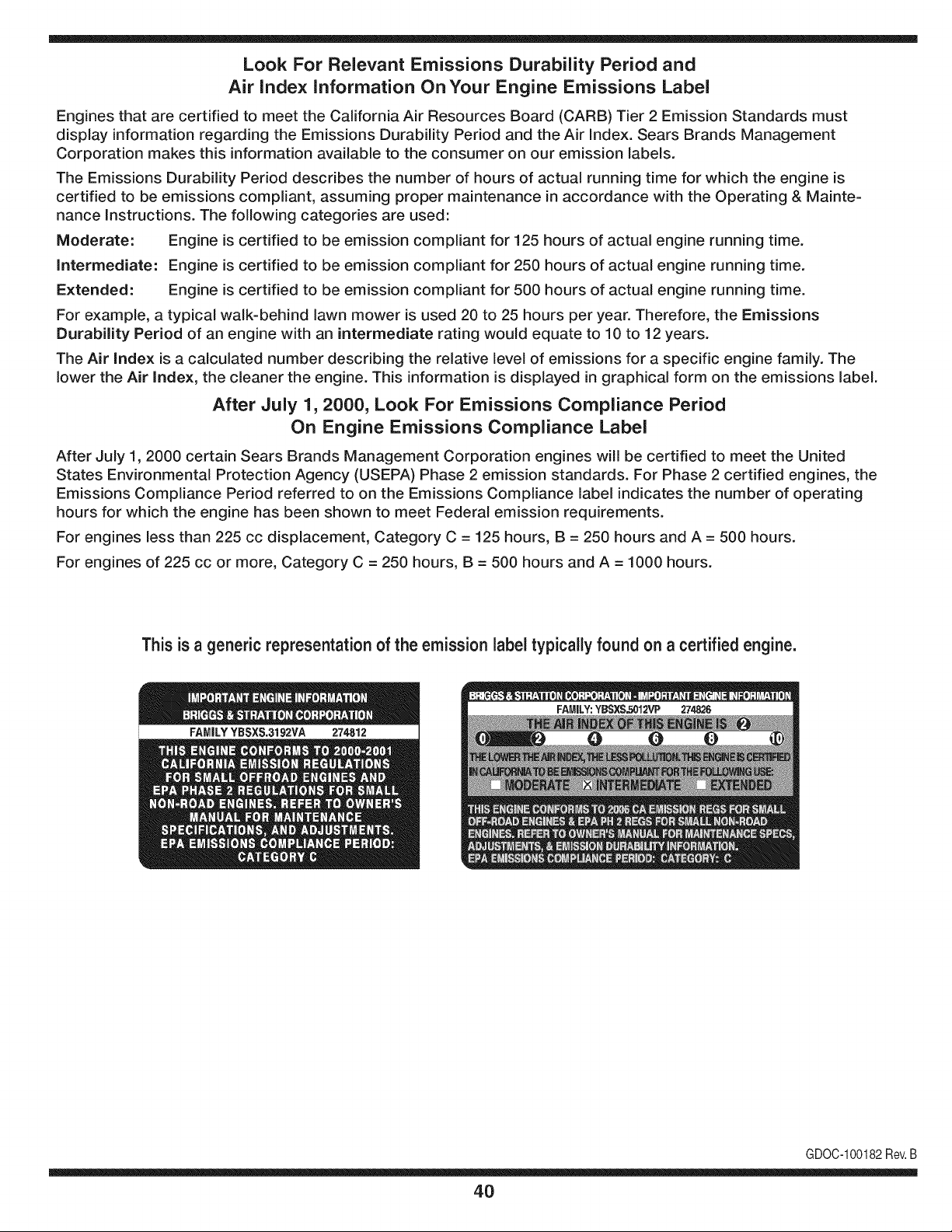
Look For Relevant Emissions Durability Period and
Air index information On Your Engine Emissions Label
Engines that are certified to meet the California Air Resources Board (CARB) Tier 2 Emission Standards must
display information regarding the Emissions Durability Period and the Air Index. Sears Brands Management
Corporation makes this information available to the consumer on our emission labels.
The Emissions Durability Period describes the number of hours of actual running time for which the engine is
certified to be emissions compliant, assuming proper maintenance in accordance with the Operating & Mainte-
nance Instructions. The following categories are used:
Moderate: Engine is certified to be emission compliant for 125 hours of actual engine running time.
Intermediate: Engine is certified to be emission compliant for 250 hours of actual engine running time.
Extended: Engine is certified to be emission compliant for 500 hours of actual engine running time.
For example, a typical walk-behind lawn mower is used 20 to 25 hours per year. Therefore, the Emissions
Durability Period of an engine with an intermediate rating would equate to 10 to 12 years.
The Air index is a calculated number describing the relative level of emissions for a specific engine family. The
lower the Air Index, the cleaner the engine. This information is displayed in graphical form on the emissions label.
After July 1,2000, Look For Emissions Compliance Period
On Engine Emissions Compliance Label
After July 1, 2000 certain Sears Brands Management Corporation engines will be certified to meet the United
States Environmental Protection Agency (USEPA) Phase 2 emission standards. For Phase 2 certified engines, the
Emissions Compliance Period referred to on the Emissions Compliance label indicates the number of operating
hours for which the engine has been shown to meet Federal emission requirements.
For engines less than 225 cc displacement, Category C = 125 hours, B = 250 hours and A = 500 hours.
For engines of 225 cc or more, Category C = 250 hours, B = 500 hours and A = 1000 hours.
This is a generic representation of the emission label typically found on a certified engine.
FAMILYYBSXS.3192VA 274812
GDOC-100182Rev.B
40
Congratulationson makinga smartpurchase.YournewCraftsman@
productis designedandmanufacturedfor yearsof dependableopera-
tion.But likeall products,it mayrequirerepairfromtimeto time.That's
whenhavinga RepairProtectionAgreementcansaveyoumoneyand
aggravation.
Here'swhatthe RepairProtectionAgreement*includes:
* Expert service byour 10,000professionalrepairspecialists
o Unlimitedserviceand no chargefor partsand laboron all
coveredrepairs
o Product replacementupto $1500if yourcoveredproductcan't be
fixed
• Discountof 10%from regularprice of serviceand relatedinstalled
partsnotcoveredby theagreement;also, 10%off regularpriceof
preventivemaintenancecheck
• Fast help by phone- we call it RapidResolution- phonesupport
froma Searsrepresentative.Thinkof usas a "talkingowner's
manual."
Onceyou purchasethe Agreement,a simplephonecall is all thatit
takesfor youto scheduleservice.Youcan call anytimedayor night,or
schedulea serviceappointmentonline.
The RepairProtectionAgreementis a risk-freepurchase.If youcancel
for any reasonduringthe productwarrantyperiod,wewill providea full
refund.Or,a proratedrefundanytimeafterthe productwarrantyperiod
expires.Purchaseyour RepairProtectionAgreementtoday!
Somelimitationsand exclusionsapply. For pricesand additional
informationin the U.S.A.call 1-800-827-6655.
*Coverage in Canadavaries on some items.Forfull details call
Sears Canadaat 1-800-361-6665.
Sears Installation Service
ForSearsprofessionalinstallationof homeappliances,garagedoor
openers,waterheaters,andothermajorhomeitems,in the U.S.A.or
Canadacall 1-800-4-MY-HOME®.
41
Declaraci6n de garantia ............................ Pagina 42
Practicas operaci6n seguras ..................... Pagina 43
Montaje ...................................................... Pagina 47
Operaci6n .................................................. Pagina 53
Servicio y Mantenimiento .......................... Pagina 58
Almacenamiento fuera de temporada ....... Pagina 65
Soluci6n de problemas .............................. Pagina 66
Acuerdo de protecci6n para reparaciones .... Pagina 71
Etiquetas de seguridad .............................. Pagina 7
Lista de piezas ........................................... Pagina 26
NOmero de servicio ................................... Cubierta
posterior
GARANTiA COMPLETA CRAFTSMAN POR DOS AltOS
P0R DOSANOSa partir dela fechade la cornpra,este productoest&garantizadopordefectosen los rnaterialesy la rnanodeobra.
Los productosdefectuososser_.nreparadossin costoo reernplazadossin costosi la reparaci6nno est,. disponible.
La presentegarantiase anula si se utilizaeste productoalgunavezparaprestarservicioscornercialeso si se Ioalquilaa otra persona.
Paraobtener informaci6nsobre el alcance de la garantiay solieitar la reparaci6no el reemplazo,visite el sitio Web:www.craftsman.com
Esta garantia cubre0NICAMENTElos defectos en los rnaterialesy en la mano de obra. Estagarantia NOcubre:
• Elernentosno renovablesque puedendesgastarsepor eluso normal,duranteel plazodela garantia,incluyendoentreotros,las barrenas,
las paletasde las barrenas,los cortadoresde desplazarniento,laszapatasantideslizantes,la placade raspado,lospasadoresde cuchilla,
la bujia,elfiltrode aire,las correasy el filtrode aceite.
• Serviciosde rnantenirnientoest_.ndar,carnbiosde aceiteo afinaci6n.
• Carnbiode neurn_.ticoso reparacionespor pinchadurascon objetosexternoscornoclavos,espinas,toconeso vidrios.
• Reernplazoo reparaci6nde neurn_.ticoso ruedascornoresultadodel desgastenormal,unaccident&o funcionarniento
o rnantenirnientoincorrectos.
• Reparacionesrequeridascornoresultadodel uso inadecuadopot partedel operador,incluyendoentreotrosel da_oocasionadoporobjetos
queirnpactanla rn_.quinay que tuercenel bastidor,el ejede labarrena,etc., o debido a queel motorrueaceleradoen exceso.
• Reparacionesnecesariasdebidoa negligenciadeloperador,incluyendoentre otros,da_osrnec_.nicoy el_ctricoocasionadopor
unalrnacenarnientono apropiado,fallaporel uso de aceitede gradoy/o cantidadnoapropiadoso falla por no dar rnantenirniento
alequipo de acuerdocon las instruccionescontenidasenel manualdel operador.
• Lirnpiezao reparacionesdel motor(sisternade combustible)debidasa combustiblequese deterrninaest,.contarninadou oxidado(viejo).
Engeneral,el combustibledebeutilizarseen unperiodono mayorde 30dias a partirde su adquisici6n.
• Eldeterioroy desgastenormalde losacabadosexteriores,o reernplazode laetiquetadel producto.
Estagarantiale otorgaderechoslegalesespecificos,pero ustedpodriagozarde otrosderechosen raz6nde su lugarde residencia.
Sears Brands Management Corporation, Hoffman Estates, IL 60179
Tipode aceitedelmotor:
Capacidaddeaceitedel motor:
Capacidaddecombustible:
Bujfas:
Separaci6nde lasbujias:
SAE 5W-30
20 onzas
3 cuartos
Torch F6RTC
.020" a .030"
N_merode rnodelo ..........................................................
N_merode sede ..............................................................
Feehade eompra .............................................................
Registrearriba el nOrnerodel rnodelo,el nOrnerode seriey la fecha
decornpra
© Sears Brands,LLC
42
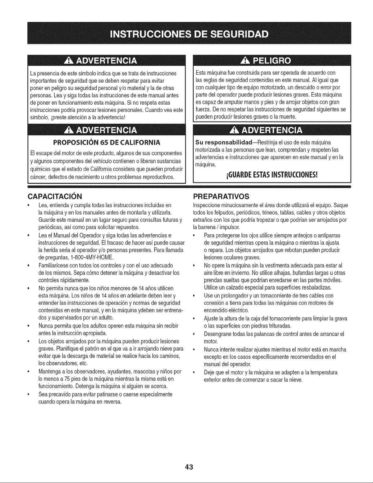
Lapresenciade este sirnboloindicaque setratade instrucciones
irnportantesde seguridadque se debenrespetarpara evitar
poneren peligrosu seguridadpersonaly/o materialy la de otras
personas.Lea y siga todaslas instruccionesdeestemanualantes
de poneren funcionarnientoestarn_.quina.Si no respetaestas
instruccionespodria provocarlesionespersonales.Cuandoveaeste
sirnbolo,ipresteatenci6na la advertencia!
PROPOSICION 65 DE CALIFORNIA
Elescapedel motordeesteproducto,algunosde suscornponentes
y algunoscornponentesdelvehiculocontieneno liberansustancias
quirnicasqueel estado de Californiaconsideraque puedenproducir
c_.ncer,defectosde nacirnientou otros problernasreproductivos.
Estarn_.quinarueconstruidapara seroperadadeacuerdocon
las reglasde seguridadcontenidasen este manual.AI igualque
concualquiertipo de equipo rnotorizado,undescuidoo errorpor
partedel operadorpuedeproducirlesionesgraves.Estarn_.quina
es capazde arnputarrnanosy piesy de arrojarobjetoscon gran
fuerza.Deno respetarlas instruccionesde seguridadsiguientesse
puedenproducirlesionesgraveso la rnuerte.
Su responsabilidad--Restrinja el usode estarn_.quina
rnotorizadaalas personasque lean,cornprendany respetenlas
advertenciase instruccionesqueaparecenen estemanualyen la
rn_.quina.
iGUARDEESTASINSTRUCCIONES!
CAPACITACiON
• Lea,entienday curnplatodaslas instruccionesincluidasen
la rn_.quinayen los rnanualesantes de rnontarlay utilizarla.
Guardeestemanualenun lugarseguroparaconsultasfuturasy
peri6dicas,asi cornoparasolicitarrepuestos.
• Leael Manualdel Operadory sigatodaslas advertenciase
instruccionesde seguridad.Elfracasode hacerasi puedecausar
la heridaseriaal operadory/o personaspresentes.Para Ilarnada
depreguntas,1-800-4MY-HOME.
• Farniliaricesecontodos los controlesy con el usoadecuado
delos rnisrnos.Sepa c6rnodetenerlarn_.quinay desactivarlos
controlesr_.pidarnente.
• No perrnitanuncaque los ni_osrnenoresde 14a_osutilicen
estarn_.quina.Los ni_osde 14a_osen adelantedebenleery
entenderlas instruccionesde operaci6ny norrnasdeseguridad
contenidasen este manual,yen la rn_.quinaydebenser entrena-
dosy supervisadospor un adulto.
• Nuncaperrnitaque los adultosoperenestarn_.quinasin recibir
antesla instrucci6napropiada.
• Losobjetosarrojadosporla rn_.quinapuedenproducirlesiones
graves.Planifiqueel patr6nenel queva air arrojandonievepara
evitarque ladescargade materialse realicehacialos carninos,
los observadores,etc.
• Mantengaa losobservadores,ayudantes,rnascotasy ni_ospor
Io rnenosa 75piesde la rn_.quinarnientrasla rnisrnaest,.en
funcionarniento.Detengala rn_.quinasi alguienseacerca.
• Seaprecavidopara evitarpatinarseo caerseespecialrnente
cuandoopera la rn_.quinaen reversa.
PR E PA RATIVO S
Inspeccionerninuciosarnenteel &teadondeutilizar&el equipo.Saque
todoslos felpudos,peri6dicos,trineos,tablas,cablesy otros objetos
extra_oscon los que podriatropezaro quepodrianser arrojadospor
labarrena/irnpulsor.
• Paraprotegerselosojos utilicesiernpreanteojosoantiparras
de seguridadrnientrasoperala rn_.quinao rnientrasla ajusta
o repara.Losobjetosarrojadosquerebotanpuedenproducir
lesionesocularesgraves.
• Noopere la rn_.quinasin la vestirnentaadecuadaparaestaral
airelibre en invierno.No utilicealhajas,bufandaslargasu otras
prendassueltasquepodrianenredarseenlas partes rn6viles.
Utiliceun calzadoespecialparasuperficiesresbaladizas.
• Useun prolongadory untornacorrientedetrescablescon
conexi6na tierraparatodaslas rn_.quinascon rnotoresde
encendidoel_ctrico.
• Ajustela alturade lacaja del tornacorrienteparalirnpiarla grava
o las superficiescon piedrastrituradas.
• Desengranetodaslas palancasde controlantesde arrancarel
motor.
• Nuncaintenterealizarajustesrnientrasel motorest,.en rnarcha
exceptoen los casosespecificarnenterecornendadosen el
manualdel operador.
• Dejeque el motor y la rn_.quinase adaptena laternperatura
exteriorantesde cornenzara sacarla nieve.
43
Manejo seguro de la gasolina
Paraevitarlesionespersonales0 daSosrnaterialestengarnucho
cuidadocuandotrabajecon gasolina.Lagasolinaes surnarnente
inflarnabley susvaporespuedencausarexplosiones.Si se derrarna
gasolinaencirna0 sobrela ropase puedelesionargravernenteya que
se puedeincendiar. L&vesela piely c&rnbiesede ropade inrnediato.
• Utilices610los recipientespara gasolinaautorizados.
• Apaguetodoslos cigarrillos,cigarros,pipasy otras fuentesde
cornbusfi6n.
• Nuncacarguecombustibleen larn&quinaen unespaciocerrado.
• Nuncasaquela tapadelcombustibleniagreguecombustible
rnientrasel motorest&caliente0 en rnarcha.
• Dejeque el motorse enfriepor I0 rnenosdos rninutosantesde
volvera cargarcombustible.
• NuncaIleneen excesoel dep6sitodecombustible.Lleneel
tanquea no rn&sde1/2pulgadapordebajode la basedel cuello
de Ilenadodejandoespacioparala dilataci6ndeIcombustible.
• Vuelvaa colocarla tapade lagasoiinay aj_stelabien.
• Lirnpieel combustibleque se hayaderrarnadosobreel motory el
equipo.Trasladela rn&quinaa otra zona.Espere5 rninutosantes
deencenderel motor.
• Nuncaalrnacenela rn&quina0 el recipientede combustibleen
unespaciocerradodondehayafuego,chispas0 luz piloto(por
ejernplo,hornos,calentadoresdeagua,calefactores,secadores
de ropa,etc.).
• Dejeque la rn_.quinase enfrieporIo rnenos5 rninutosantesde
guardarla.
• NuncaIlenelos recipientesen el interiordeunvehiculoo carni6n
ocaja de rernolquecon recubrirnientospl_.sticos.Coloque
siernprelos recipientesen el pisoy lejosdel vehiculoantesde
Ilenarlos.
• Sies posible,retireel equipoa gasolinadelcarni6no rernolque
y II_neloen el suelo.Siestonoes posible,Ileneel equipoen un
rernolquecon contenedorport_.til,en vez dedesdeunaboquilla
dispensadoradegasolina.
• Mantengala boquilladispensadoraen contactocon el hordedel
dep6sitode combustibleo con la aberturadel recipienteentodo
rnornento,hastaterrninarla carga.No utiliceundispositivode
apertura/cierrede boquilla.
FUNCIONANIIENTO
• No pongalas rnanoso los piescerca delas piezasrotatorias,
en lacajade la barrena/ irnpulsoro en el rnontajedelcanalde
descarga.Hacercontactocon piezasgiratoriaspuederesultaren
laarnputaci6nde rnanoso pies.
• La palancadecontrolde la barrena/ irnpulsores un dispositivo
de seguridad.Nuncaevite su funcionarniento.De hacerlola
operaci6nde la rn_.quinaes riesgosay puedeocasionarlesiones.
• Las palancasde control debenfuncionarbienen arnbasdirec-
cionesy regresarautorn_.ticarnentea la posici6nde desengrane
cuandose lassuelta.
• Nuncaoperela rn_.quinasi faltaunrnontajedelcanalo si el
rnisrnoest,. daSado.Mantengatodoslosdispositivosde seguri-
daden su lugaryen funcionarniento.
• Nuncaenciendaelmotor en espacioscerradoso en una zona
con pocaventilaci6n.El escapedel motorcontienernon6xidode
carbono,ungas inodoroy letal.
• Noutilice la rn_.quinabajo la influenciadelalcoholo las drogas.
• El silenciadory el motorse calientany puedencausarquernadu-
ras.Nolos toque.Mantengaa los niSosalejados.
• Seasurnarnenteprecavidocuandooperelarn_.quinasobreuna
superficiecon gravao cuandola cruce.Mant_ngasealerta porsi
se presentanpeligrosocultoso tr_.nsito.
• Tengacuidadocuandocarnbiede direcci6no cuandooperela
rn_.quinaen pendientes.
• Planifiqueel patr6nenel queva a ir arrojandonieveparaevitar
que ladescargade materialse produzcahacialas ventanas,
las paredes,losautorn6viles,etc.y evitarasi posiblesdaSos
rnaterialeso lesionesproducidaspor los rebotes.
• Nuncadirija la descargahacialos niSos,los observadoreso las
rnascotasni dejequenadiese pare delantede la rn_.quina.
• Nosobrecarguela capacidadde la rn_.quinatratandode sacarla
nievernuyr_.pidarnente.
• Nuncaopereesta rn_.quinasin buenavisibilidado ilurninaci6n.
Siernpredebeestar segurode queest,.bienafirrnadoy su-
jetandofirrnernentelas rnanijas.Carnine,nuncacorra.
• Cortela corrientea la barrena/ irnpulsorcuandotransportela
rn_.quinao cuandola rnisrnanoest,.en uso.
• Nuncaoperela rn_.quinaa alta velocidadde desplazarniento
sobresuperficiesresbaladizas.Mirehaciaabajoy haciaatr_.sy
tengacuidadocuandovayarnarchaatr_.s.
• Si la rn_.quinacornenzaraavibrarde rnaneraanorrnal,detengael
motor,desconecteel cablede labujiay p6ngalade rnaneraque
hagarnasacontrael motor.Inspeccionela rn_.quinarninuciosa-
rnenteparaver si est,. daSada.Reparetodos los daSosantesde
encendery operarla rn_.quina.
• Desengranetodas las palancasde controly detengael motor
antesde dejar la posici6nde operaci6n(detr_.sde las rnanijas).
Esperea que labarrena/ irnpulsorse detengaporcornpleto
antesde destaparel rnontajedelcanalo realizarajustese
inspecciones.
• Nuncapongalas rnanosen las aberturasdedescargao de
recolecci6n.Utilicesiernprela herrarnientade lirnpiezaquese
adjuntaparadestaparla aberturade descarga.Nodestapeel
rnontajedel canal rnientrasel motorest,.en funcionarniento.
Antesde destaparlo,apagueel motory perrnanezcadetr_.sde las
rnanijashastaque todaslas partes rn6vilesse hayandetenido.
• Uses61ounionesy accesoriosaprobadospor el fabricante(por
ejernplo,pesaspara las ruedas,cadenasparalos neurn_.ticos,
cabinas,etc.).
44
• Paraencenderel motor,jale de lacuerdalentarnentehastaque
sientaresistencia,luegojale r_.pidarnente.Elreplieguer_.pidode
la cuerdade arranque(tensi6nde retroceso)le jalar_,la rnanoy
el brazohaciael motorrn_.sr_.pidode Io queusted puedesoltar.
El resultadopuedenserhuesosrotos,fracturas,hernatornaso
esguinces.
• Si se presentansituacionesqueno est_.nprevistasen este
manual,seacuidadosoy use el sentidocornOn.P6ngaseen
contactocon Asistenciaal Clienteparasolicitarayuday el
nornbredeldistribuidorde serviciorn_.scercano.
MANTENIMIENTO Y ALMACENAMIENTO
• Nuncaalterelos dispositivosde seguridad.Controleperi6dica-
rnenteque funcionencorrectarnente.Rernitasea las secciones
demantenirnientoy ajustede este manual.
• Antesde realizarla lirnpieza,repararo revisarla rn_.quina,
desengranetodas laspalancasdecontroly detengael motor.
Esperea quela barrena/ irnpulsorse detengapor cornpleto.
Desconecteel cablede la bujfay p6ngalohaciendornasacontra
el motorparaevitarquese enciendaaccidentalrnente.
• Controlefrecuenternentequetodos lospernosy tornillosest_n
bienajustadosparacornprobarque la rn_.quinase encuentra
encondicionessegurasde funcionarniento.Adern_.s,hagauna
inspecci6nvisual de larn_.quinaparaverificarsi est,.da_ada.
• No carnbielaconfiguraci6ndel reguladordelmotorni acelere
dernasiadoel rnisrno.El reguladordelmotorcontrolala velocidad
rn_.xirnasegurade funcionarnientodelmotor.
• Las placasde raspadoy las zapatasantideslizantesquese
usancon la rn_.quinaquitanievese desgastany se da_an.
Paraprotegersu seguridad,verifiquefrecuenternentetodos los
cornponentesy reernpl_.celoss61ocon partesde los fabricantes
deequiposoriginales(OEM)."i El usode piezasqueno curnplen
con lasespecificacionesdel equipooriginalpuederesultaren
rendirnientoinadecuadoadern_.sde poneren riesgola seguri-
dad!"
• Reviselas palancasde controlperi6dicarnentepara verificar
queengraneny desengranenadecuadarnentey ajOstelossi es
necesario.Consultela secci6nde ajustesdeeste manualdel
operadorparaobtenerinstrucciones.
• Mantengao reernplacelasetiquetasde seguridade instrucciones
segQnseanecesario.
• Respetelas norrnasreferentesa ladisposici6ncorrectay las
reglarnentacionessobregasolina,aceite,etc. paraprotegerel
medicarnbiente.
• Antesdealrnacenarlarn_.quinaenci_ndalaunosrninutospara
sacarla nievequehayaquedadoen larnisrnay paraevitarasi
quese congelela barrena/irnpulsor.
• SegOnla Cornisi6nde Seguridadde Productosparael Consu-
rnidorde los EstadosUnidos(CPSC)y la Agenciade Protecci6n
Arnbientalde los EstadosUnidos(EPA),este productotieneuna
vida Qtilmediadesiete (7) a_os, 6 60 horasde funcionarniento.
AI finalizarla vida Otilmedia,adquieraunarn_.quinanuevao
hagainspeccionaranualrnente_stapor un distribuidordeservicio
autorizadoparacerciorarsede quetodoslos sisternasrnec_.nicos
y deseguridadfuncionancorrectarnentey notienenexcesivo
desgaste.Si no Iohace, puedenproducirseaccidentes,lesiones
o rnuerte
• Nuncaalrnacenela rn_.quinao el recipientede combustibleen un
espaciocerradodondehayafuego,chispaso luz pilotocornopor
ejernplo,calentadoresde agua,hornos,secadoresde ropa,etc.
• Consultesiernpreel manualdel operadorparaobtener
instruccionesadecuadaspara elalrnacenarnientofuerade
ternporadaVerifiquefrecuenternentelaIfneade combustible,el
tanque,el tap6n,y losaccesoriosbuscandorajaduraso perdidas.
Reernplacede ser necesario.
• Nod_ arranqueal motorsi noest,. labujiade encendido.
NO MODIFIQUE EL MOTOR
Paraevitarlesionesgraveso larnuerte,nornodifiqueel motorbajo
ningunacircunstancia.Si carnbiala configuraci6ndel reguladorel
motorpuededescontrolarsey operara velocidadesinseguras.Nunca
carnbiela configuraci6ndef_.bricadel reguladordel motor.
AVISO REFERIDO A EMISIONES
Losrnotoresque est&ncertificadosy curnplencon las regulaciones
de ernisionesfederalesEPAy de Californiapara SORE(Equipos
peque_ostodoterreno)est_.ncertificadosparaoperarcon gasolina
cornOnsinplornoy puedenincluirlossiguientessisternasde control
de ernisiones:Modificaci6ndemotor(EM) y catalizadorde tresvias
(TWO)si est_.nequipadosde esa rnanera.
GUARDACHISPAS
Estarn&quinaest,. equipadacon unmotorde cornbusti6ninternay
nodebe ser utilizadaen o cercade unterrenoagrestecubiertopor
bosque,rnalezaso hierbaexceptosi el sisternade escapedelmotor
est,.equipadocon unarnortiguadorde chispasque curnplaconlas
leyeslocaleso estatalescorrespondientes,encaso de haberlas.
Sise utilizaun arnortiguadordechispasel operadorIo debernantener
en condicionesde usoadecuadas.Enel Estadode Californialas
rnedidasanteriorrnenternencionadassonexigidaspor ley (Arficulo
4442del C6digode RecursosPOblicosde California).Es posible
queexistanleyessirnilaresen otros estados.Lasleyesfederalesse
aplicanen territoriosfederales.
Puedeconseguirelarnortiguadorde chispasparael silenciadora
travesde sudistribuidorautorizadode rnotoreso poni_ndoseen
contactocon el departarnentodeservicios.
45
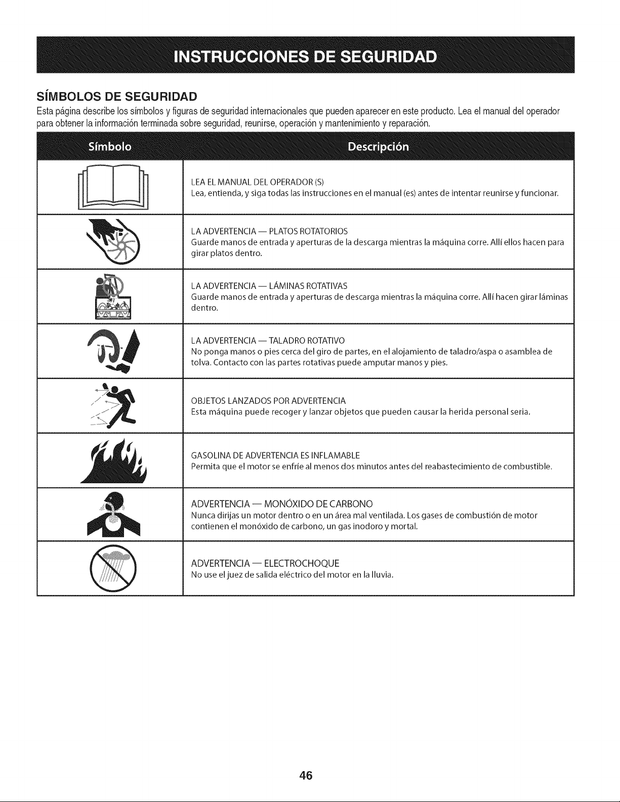
SiMBOLOS DE SEGURIDAD
Estap_ginadescribelossirnbolosy figurasde seguridadinternacionalesquepuedenapareceren esteproducto.Lea el manualdel operador
)araobtenerla inforrnaci6nterrninadasobreseguridad,reunirse,operaci6ny rnantenimientoy reparaci6n.
i
i
LEAELMANUAL DELOPERADOR(S)
Lea,entienda, y siga todas lasinstrucciones en el manual (es)antes de intentar reunirse y funcionar.
LA ADVERTENCIA -- PLATOS ROTATORIOS
Guarde manos de entrada y aperturas de la descarga mientras la m_iquina corre. Alli ellos hacen para
girar platos dentro.
LA ADVERTENCIA- LAMINASROTATIVAS
Guarde manos de entrada y aperturas de descarga mientras la m_iquina corre. Alli hacen girar I_iminas
dentro.
LA ADVERTENCIA -- TALADRO ROTATIVO
No ponga manos o pies cerca del giro de partes, en el alojamiento de taladro/aspa o asamblea de
tolva. Contacto con las partes rotativas puede amputar manos y pies.
OBJETOS LANZADOS POR ADVERTENCIA
Esta m_iquina puede recoger y lanzar objetos que pueden causar la herida personal seria.
GASOLINA DE ADVERTENCIA ESINFLAMABLE
Permita que el motor se enfrie al menos dos minutos antes del reabastecimiento de combustible.
ADVERTENCIA -- MONOXIDO DE CARBONO
Nunca dirijas un motor dentro o en un _irea mal ventilada. Los gases de combusti6n de motor
contienen el mon6xido de carbono, un gas inodoro y mortal.
ADVERTENCIA- ELECTROCHOQUE
No use eljuez de salida el6ctrico del motor en la Iluvia.
46
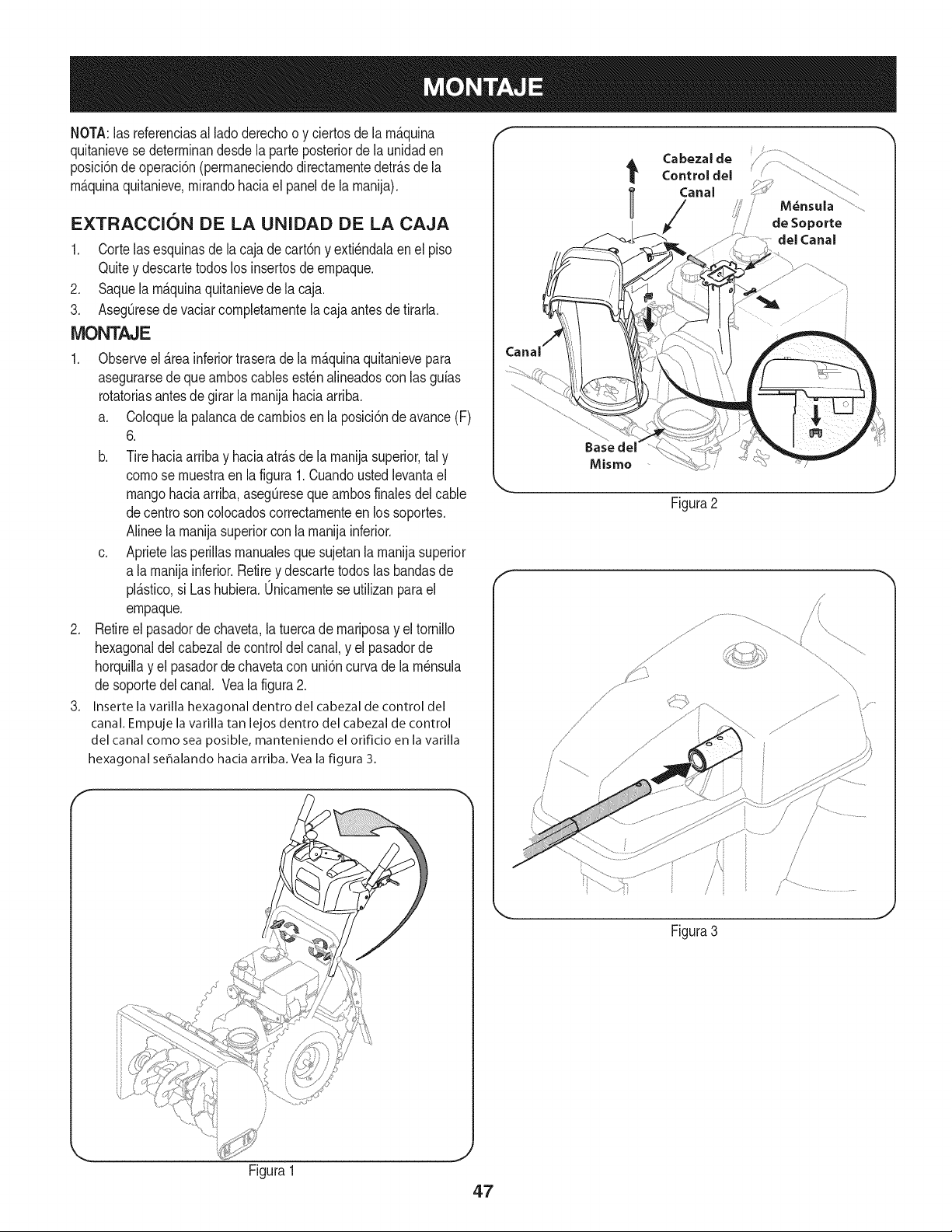
NOTA:las referendasal ladederechoo y ciertosde la m_.quina
quitanievese determinandesdela parteposteriorde la unidaden
posM6nde operaci6n(permaneciendodirectamentedetr_.sde la
m_.quinaquitanieve,mirandohada el panelde la manija),
EXTRACCION DE LA UNIDAD DE LA CAJA
1. Cortelasesquinasdela cajade cart6ny exti_ndalaenel piso
Quitey descartetodoslos insertosde empaque.
2. Saquela m_.quinaquitanievede la caja.
3. AsegQresede vaciarcompletamentela cajaantesde tirarla.
MONTAJE
1. Observeel _.reainferiortraserade la m_.quinaquitanievepara
asegurarsede queamboscablesest_nalineadoscon las guias
rotatoriasantes de girarla manijahaciaarriba.
a. Coloquela palancadecambiosen la posici6ndeavance(F)
6.
b. Tirehaciaarriba y haciaatrAsde lamanijasuperior,tal y
comese muestraen la figura1.Cuandoustedlevantael
mangohaciaarriba,asegQreseque ambosfinalesdel cable
decentre soncolocadoscorrectamenteen lossoportes.
Ninee la manijasuperiorconla manijainferior.
c. Aprietelasperillasmanualesque sujetanlamanijasuperior
a lamanijainferior.Retirey descartetodoslas bandasde
plAstico,si Las hubiera.0nicamentese utilizanpara el
empaque.
2. Retireel pasadordechaveta,la tuercade mariposay eltornillo
hexagonaldel cabezaldecontroldelcanal,y el pasadorde
horquillay el pasadordechavetacon uni6ncurva de lam_nsula
desoportedel canal. Veala figura2.
3. Insertela varillahexagonaldentro del cabezalde controldel
canal.Empujela varillatan lejosdentro del cabezalde control
del canalcomeseaposible,manteniendoel orifido en lavarilla
hexagonalseffalandohaciaarriba.Vealafigura 3.
Cabezalde
t Control del
l Canal
/
de Seporte
clel Canal
Baseclel
Mismo
J
Figura2
\
Figura3
Figura1
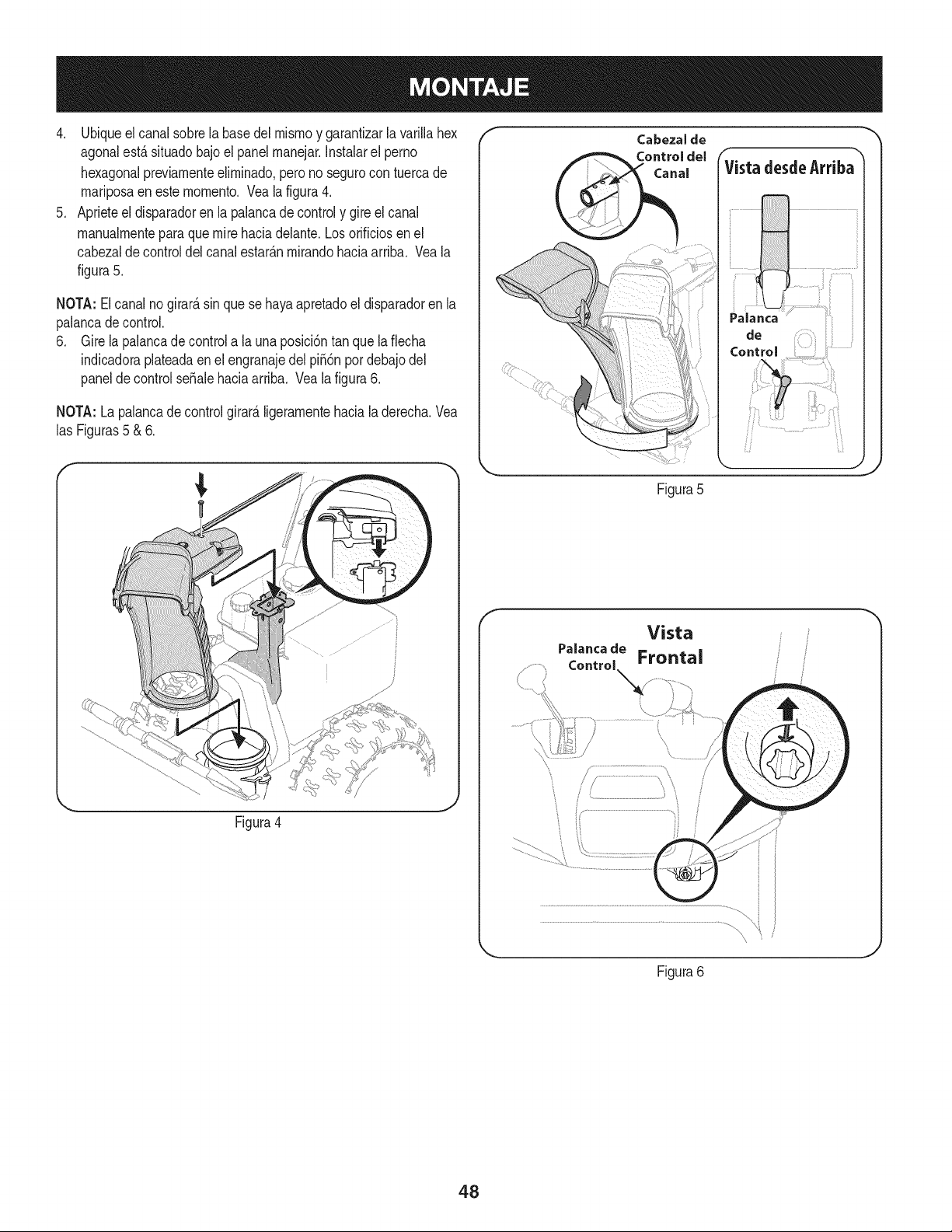
4. Ubiqueelcanalsobrelabasedelmismoygarantizarlavarillahex
agonalest,.situadobajoelpanelmanejar.Instalarelperno
hexagonalpreviamenteeliminado,peronosegurocontuercade
mariposaenestemomento.Vealafigura4.
5. Aprieteeldisparadorenlapalancadecontrolygireelcanal
manualmenteparaquemirehaciadelante.Losorificiosenel
cabezaldecontroldelcanalestar_.nmirandohaciaarriba.Veala
figura5.
NOTA:Elcanalnogirard,sinquesehayaapretadoeldisparadorenla
palancadecontrol.
6. Girelapalancadecontrolalauna)osici6ntanquelaflecha
indicadoraplateadaenelengranajedelpii6npordebajodel
paneldecontrolseSalehaciaarriba.Vealafigura6.
NOTA:Lapalancadecontrolgirard,ligeramentehacialaderecha.Vea
lasFiguras5&6.
/*
_, ,J
Figura4
f
Figura5
f
Vista
Figura6
48
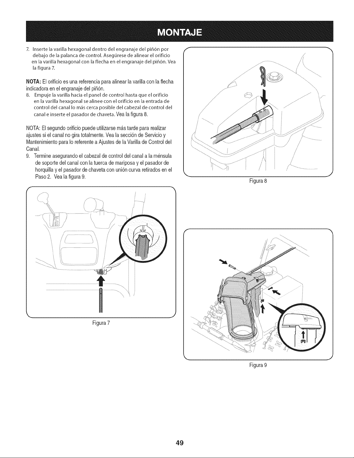
7. Inserte la varilla hexagonal dentro del engranaje del pi_dn por
debajo de la palanca de control. AsegOrese de alinear el orificio
en la varilla hexagonal con la flecha en el engranaje del pi_6n. Vea
la figura 7.
NOTA:El orificioes unareferenciaparaalinear lavarillacon la flecha
indicadoraen el engranajedel pi56n.
8. Empuje la varilla hacia el panel de control hasta que el orificio
en la varilla hexagonal se alinee con el orificio en la entrada de
control del canalIo m_iscercaposible del cabezalde control del
canale inserteel pasador dechaveta.Vea la figura8.
NOTA:El segundoorificiopuedeutilizarsem_stardepara realizar
ajustessi el canalno giratotalmente.Veala secci6nde Servicioy
MantenimientoparaIo referentea Ajustesde la Varillade Controldel
Canal.
9. Termineasegurandoel cabezaldecontroldel canala lam_nsula
desoportedel canalcon la tuercade mariposay el pasadorde
horquillay el pasadordechavetacon uni6ncurva retiradosen el
Paso2. Vealafigura9.
Figura7
f
j.
Figura8
Figura 9
J
49
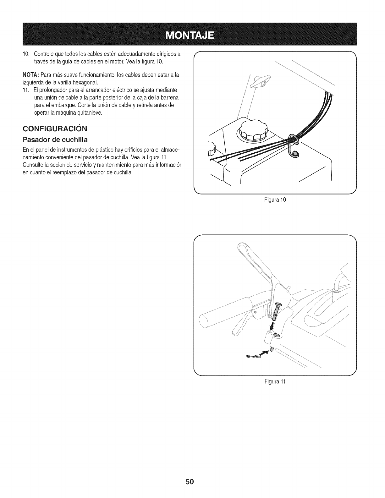
10. Controleque todosloscablesest_nadecuadarnentedirigidosa "" "
travesde la gufadecablesenel motor.Veala figura 10.
NOTA: Pararn_.ssuavefuncionarniento,los cablesdebenestara la
izquierdade la varillahexagonal.
11. El prolongadorparael arrancadorel_ctricose ajustarnediante
unauni6n de cablea la parteposteriorde la cajade la barrena
parael ernbarque.Cortela uni6ndecable y refirelaantesde
operarla rn_.quinaquitanieve.
CONFIGURACI6N
Pasador de cuchilla
Enel panelde instrurnentosde pl_.sticohay orificiosparael alrnace-
narnientoconvenientedelpasadordecuchilla.Veala figura 11.
Consultela seciondeservicioy rnantenirnientopararn_.sinforrnaci6n
encuantoel reernplazodel pasadorde cuchiNa.
i
\ I
.J
Figura10
f
Figura11
5O
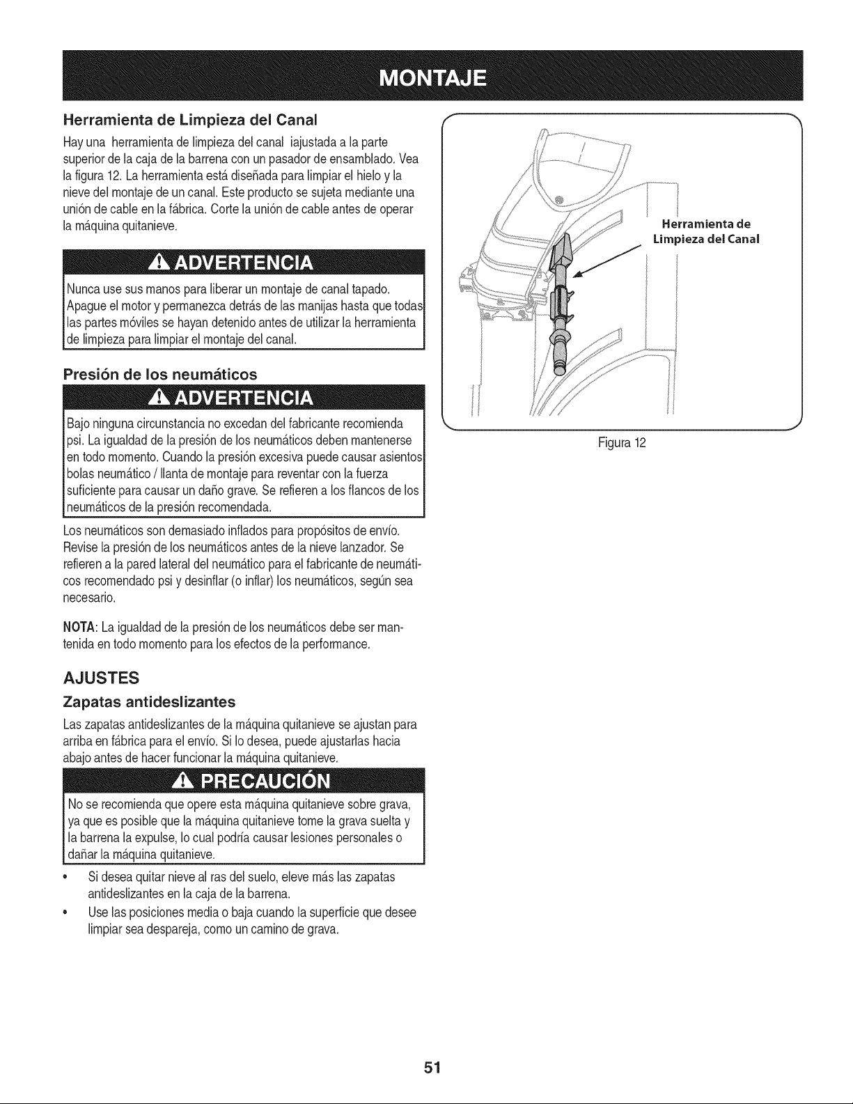
Herramienta de Lirnpieza del Canal
Hayuna herrarnientade lirnpiezadel canal iajustadaa laparte
superiorde lacaja dela barrenaconun pasadordeensarnNado.Vea
la figura12.La herrarnientaest&diseSadaparalirnpiarel hMo y la
nievedel rnontajede uncanal.Esteproductose sujetarnedianteuna
uni6nde cableen laf&brica.Cortela uni6nde cableantes de operar
la rnAquinaquitanieve.
Nuncause sus rnanosparaliberarun rnontajedecanaltapado.
Apagueel motory perrnanezcadetr_.sde las rnanijashastaque todas
las partesrn6vilesse hayandetenidoantesde utilizar la herrarnienta
delirnpiezaparalirnpiarel rnontajedel canal.
Presi6n de los neumaticos
Bajoningunacircunstanciano excedandelfabricanterecornienda
psi.La igualdadde lapresi6nde los neurn_.ticosdeben rnantenerse
entodo mornento.Cuandola presi6nexcesivapuedecausarasientos
bolasneurn_.tico/ Ilantadernontajepara reventarcon lafuerza
suficienteparacausarun da_o grave.Se refierena los fiancosde los
neurn_.ticosde la presi6nrecornendada.
Losneurn_.ticossondernasiadoinfladosparaprop6sitosde envio.
Revisela presi6nde los neurn_.ticosantes dela nievelanzador.Se
refierena la paredlateraldel neurn_.ticoparael fabricantede neurn_.ti-
cosrecornendadopsi y desinfiar(o inflar)los neurn_.ticos,segQnsea
necesario.
Herramienta de
Limpieza del (;anal
Figura12
NOTA:La igualdadde la presi6nde los neurn_.ticosdebe set man-
tenidaen todo rnornentopara los efectosde la performance.
AJUSTES
Zapatas antideslizantes
Laszapatasantideslizantesdela rn_.quinaquitanieveseajustanpara
arribaen f_.bricaparael envio. Si Io desea,puedeajustarlashacia
abajoantesde hacerfuncionarla rn_.quinaquitanieve.
Nose recorniendaqueopereestarn_.quinaquitanievesobregrava,
ya que es posiblequela rn_.quinaquitanievetome la gravasuelta y
labarrenala expulse,Iocual podriacausarlesionespersonaleso
da_arla rn_.quinaquitanieve.
• Sideseaquitarnieveal rasdel suelo,elevern_.slaszapatas
antideslizantesen la cajade la barrena.
• Uselas posicionesmediao bajacuandola superficieque desee
lirnpiarseadespareja,cornoun carninodegrava.
51
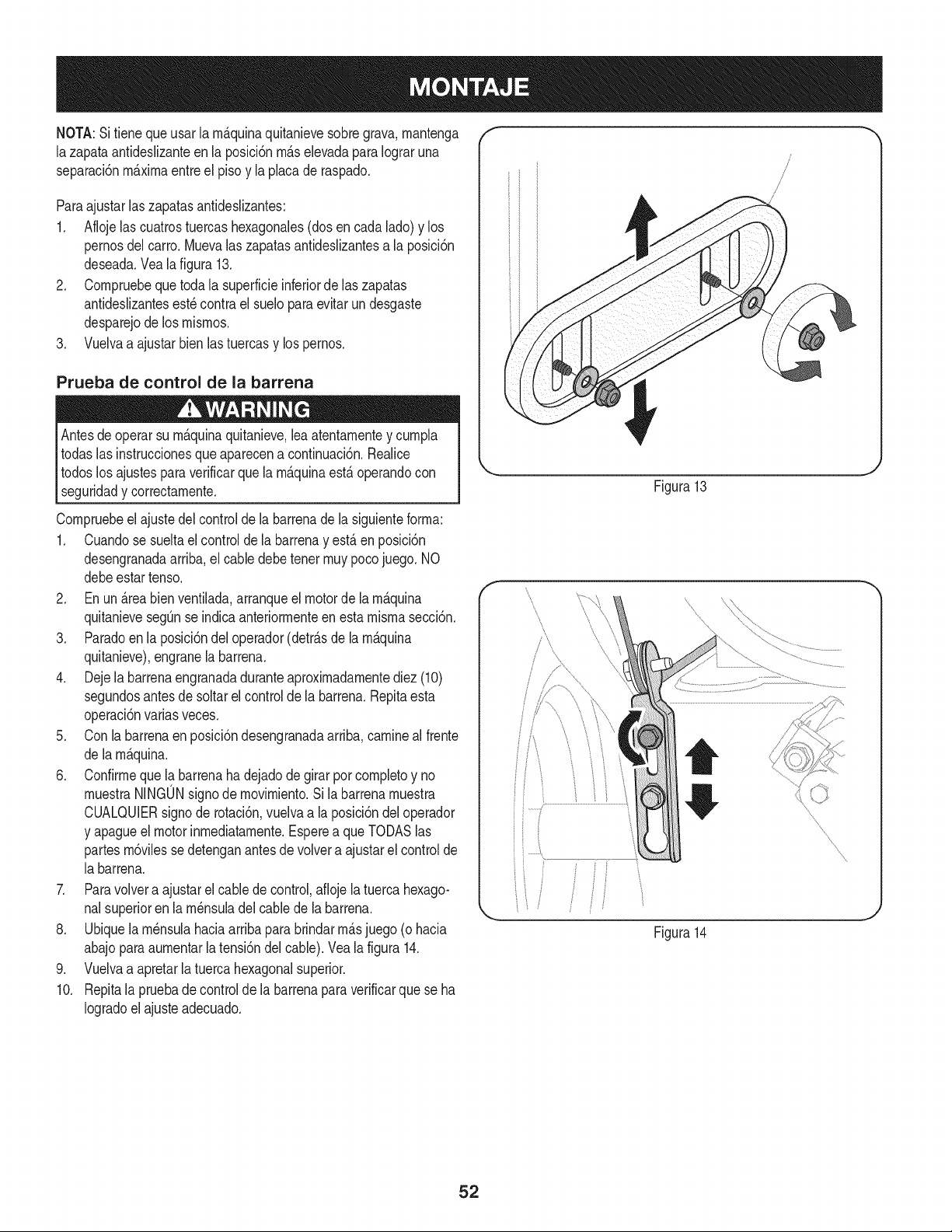
NOTA:Si tieneque usar la rn_.quinaquitanievesobregrava,rnantenga
lazapata antideslizanteen la posici6nrn_.selevadaparaIograruna
separaci6nrn_.xirnaentreel pisoy laplacade raspado.
Paraajustarlaszapatasantideslizantes:
1. Aflojelas cuatrostuercashexagonales(dosencada lado)y los
pernosdel carro.Muevalas zapatasantideslizantesa la posici6n
deseada.Veala figura 13.
2. Cornpruebequetoda la superficieinferiorde hs zapatas
antideslizantesest_contra el sueloparaevitar un desgaste
desparejode los rnisrnos.
3. Vuelvaa ajustarbienlastuercasy lospernos.
Prueba de control de la barrena
lAntes operarsu rn_.quinaquitanieve, y curnpla
de leaatentarnente
todaslasinstruccionesqueaparecena continuaci6n.Realice
todoslosajustesparaverificarque la rn_.quinaest,. operandocon
seguridady correctarnente.
Cornpruebeel ajustedel controlde la barrenadela siguienteforrna:
1. Cuandose sueltael controlde la barrenay est,.en posici6n
desengranadaarriba,el cabledebetenet rnuypocojuego. NO
debeestartenso.
2. En un _.reabien ventilada,arranqueel motorde larn_.quina
quitanievesegt]nse indicaanteriorrnenteen estarnisrnasecci6n.
3. Paradoen la posici6ndel operador(detr_.sde la rn_.quina
quitanieve),engranela barrena.
4. Dejela barrenaengranadaduranteaproxirnadarnentediez (10)
segundosantesde soltarel controlde la barrena.Repitaesta
operaci6nvarias veces.
5. Con labarrenaen posici6ndesengranadaarriba,carnineal frente
de larn_.quina.
6. Confirrneque la barrenahadejadodegirar por cornpletoy no
rnuestraNINGONsignode rnovirniento.Sila barrenarnuestra
CUALQUIERsignode rotaci6n,vuelvaa la posici6ndeloperador
y apagueel motorinrnediatarnente.Esperea queTODASlas
partesrn6vilessedetenganantesde volvera ajustarel controlde
la barrena.
7. Paravolvera ajustarel cablede control,aflojela tuercahexago-
nalsuperioren la rn_nsuladelcablede la barrena.
8. Ubiquela rn_nsulahaciaarribapara brindarrn_.sjuego (ohacia
abajoparaaurnentarla tensi6ndelcable).Veala figura14.
9. Vuelvaa apretarla tuercahexagonalsuperior.
10. Repitala pruebadecontrolde la barrenapara verificarquese ha
Iogradoel ajusteadecuado.
f
J
!
,i
J
Figura13
f
Figura14
52
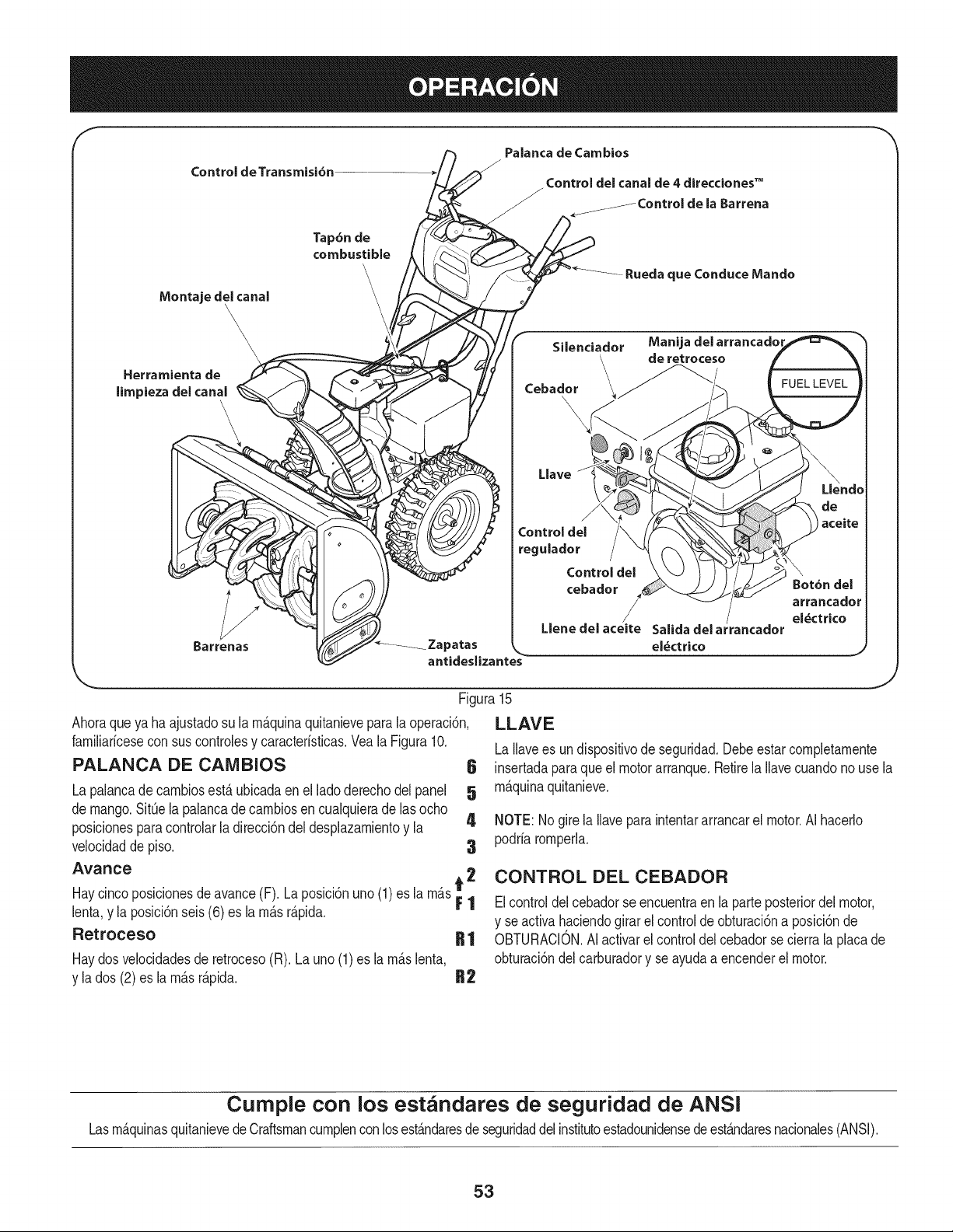
Control de Transmisi6n
Palanca de Cambios
ControJ del canal de 4 direcciones TM
la Barrena
Montaje deJ canal
\,
\
Herramienta de
limpieza del canaJ
Barrenas
Tap6n de
combustible
\
\
\
\
_Zapatas
antidesJizantes
Silenciador Manija del arrancadol
_\ de retroceso
Cebador \\__
LJave
Control deJ
regulador
Control del
cebador
LJene del aceite
eJ_ctrico
Ahoraqueya haajustadosu la rn_.quinaquitanievepara la operaci6n,
farniliaricesecon suscontrolesy caracteristicas.Vea la Figura10.
PALANCA DE CAMBIOS 6
La palancadecarnbiosest,. ubicadaen el ladoderechodelpanel 5
de mango.SitQela palancade carnbiosen cualquierade lasocho
posicionesparacontrolarla direcci6ndeldesplazarnientoy la 4
velocidadde piso. 3
Avarice
Haycincoposicionesdeavance(F). Laposici6nuno(1)es la rn_.st 2
F1
lenta,y la posici6nseis (6) es la rn_.sr_.pida.
Retroceso R 1
Haydosvelocidadesde retroceso(R). Launo (1)es la rn_.slenta,
y la dos (2) es larn_.sr_.pida. R2
Figura15
LLAVE
J
LaIlavees undispositivode seguridad.Debeestarcompletarnente
insertadaparaque elmotorarranque.Retirela Ilavecuandonouse la
rn_.quinaquitanieve.
NOTE:Nogire la Ilaveparaintentararrancarel motor.AI hacerlo
podriarornperla.
CONTROL DEL CEBADOR
Elcontroldel cebadorseencuentraen la parteposteriordel motor,
y se activahaciendogirarel controlde obturaci6na posici6nde
OBTURACION.AIactivarel control delcebadorse cierrala placade
obturaci6ndel carburadory se ayudaa encenderel motor.
Cumple con los estandares de seguridad de ANSI
Lasrn_.quinasquitanievede Craftsmancurnplencon losest_.ndaresde seguridaddel institutoestadounidensedeest_.ndaresnacionales(ANSI).
53
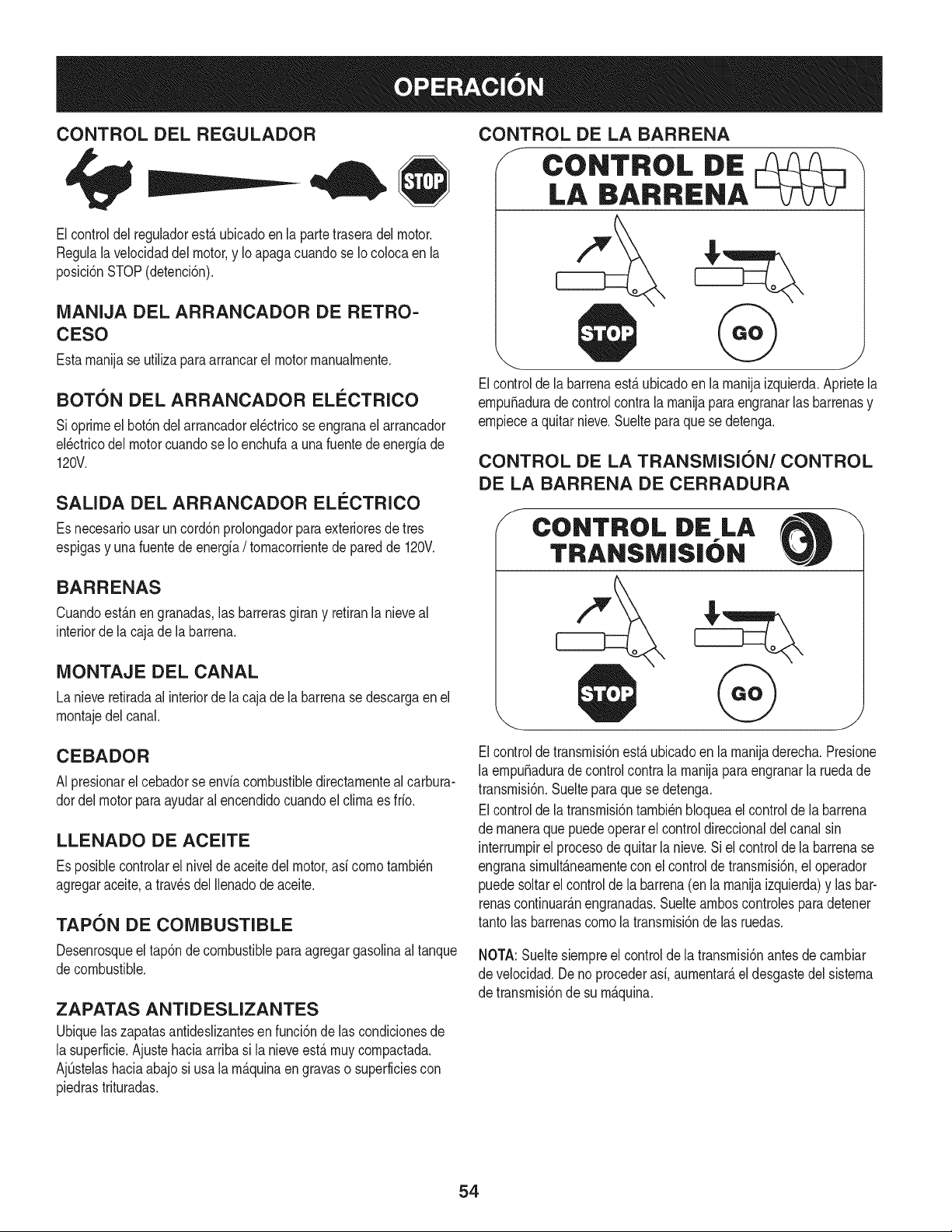
CONTROL DEL REGULADOR
Elcontroldel reguladorest,.ubicadoen la partetraseradelmotor.
Regulala velocidaddel motor,y Io apagacuandose Iocolocaen la
posici6nSTOP(detenci6n).
MANIJA DEL ARRANCADOR DE RETRO-
CESO
Estarnanijase utilizaparaarrancarel motorrnanualrnente.
BOTON DEL ARRANCADOR ELECTRICO
Sioprirneel bot6ndelarrancadorel_ctricoseengranael arrancador
el_ctricodel motorcuandose Io enchufaa unafuentede energiade
120V.
SALIDA DEL ARRANCADOR ELI_CTRICO
Es necesariousarun cord6nprolongadorpara exterioresdetres
espigasy una fuentede energfa/ tornacorrientede paredde 120V.
BARRENAS
Cuandoest_.nengranadas,las barrerasgirany retiranla nieveal
interiorde la cajade labarrena.
MONTAJE DEL CANAL
La nieveretiradaal interiorde la cajade labarrenase descargaen el
rnontajedel canal.
CONTROL DE LA BARRENA
F CONTROL DiE
LA BARRENA
Elcontrolde labarrenaest,.ubicadoen larnanijaizquierda.Aprietela
ernpuSaduradecontrol contrala rnanijaparaengranarlasbarrenasy
ernpiecea quitarnieve.Suelteparaquese detenga.
CONTROL DE LA TRANSMISION/CONTROL
DE LA BARRENA DE CERRADURA
f
CONTROL DE LA
TRANSIVI|S|ON
CEBADOR
N presionarel cebadorse enviacombustibledirectarnentealcarbura-
dordel motorparaayudaralencendidocuandoel clirnaes frio.
LLENADO DE ACEITE
Es posiblecontrolarel nivelde aceitedel motor,asi cornotarnbi_n
agregaraceite,a travesdel Ilenadode aceite.
TAPON DE COMBUSTIBLE
Desenrosqueel tap6nde combustiblepara agregargasolinaaltanque
decombustible.
ZAPATAS ANTI D ESLIZANTES
Ubiquelaszapatasantideslizantesen funci6ndelas condicionesde
la superficie.Ajustehaciaarriba si la nieveest,.rnuycornpactada.
AjQstelashaciaabajosi usala rn_.quinaen gravaso superficiescon
piedrastrituradas.
Elcontrolde transrnisi6nest,.ubicadoen la rnanijaderecha.Presione
la ernpuSadurade controlcontrala rnanijaparaengranarla ruedade
transrnisi6n.Sueltepara que se detenga.
Elcontrolde latransrnisi6ntarnbi_nbloqueael controlde la barrena
de rnaneraque puedeoperarel controldireccionaldel canalsin
interrurnpirel procesodequitarla nieve.Siel controlde la barrenase
engranasirnult_.nearnentecon el controlde transrnisi6n,el operador
puedesoltarel controlde labarrena(enla rnanijaizquierda)y lasbar-
renascontinuar_.nengranadas.Sueltearnboscontrolesparadetener
tantolas barrenascornola transrnisi6nde las ruedas.
NOTA:Sueltesiernpreel controlde la transrnisi6nantesde carnbiar
de velocidad.Deno procederasi, aurnentar_,el desgastedel sisterna
de transrnisi6nde su rn_.quina.
54
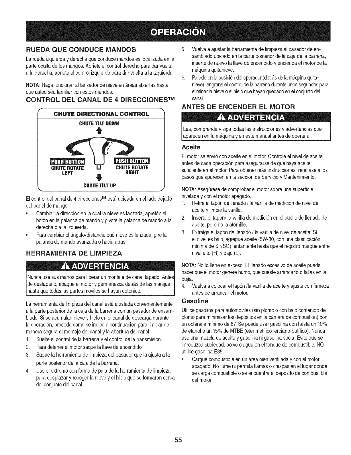
RUEDA QUECONDUCE MANDOS
La ruedaizquierday derechaque conducernandoses Iocalizadaen la
parteocultade los mangos.Aprieteel controlderechoparadarvuelta
a laderecha;aprieteelcontrolizquierdoparadarvueltaa la izquierda.
NOTA:Hagafuncionaral lanzadordenieveen_.reasabiertashasta
queusted seafamiliarconestosrnandos.
CONTROL DEL CANAL DE 4 DIRECCIONES TM
CHUTE DiRECTiONAL CONTROL
CHUTETiLTDOWN
t
CHUTEROTATE CHUTEROTATE
LEFT R|GHT
#
CHUTETiLTUP j
Elcontroldel canalde4 direccionesTM est,. ubicadaen el ladodejado
delpanel de mango.
• Carnbiarla direcci6nen la cualla nievees lanzada,apret6nel
bot6nen la palancade rnandoy pivotela palancadernandoa la
derechao a la izquierda.
• Paracarnbiarel _.ngulo/distanciaqu_nievees lanzada,gire la
palancade rnandoavanzadao haciaatr_.s.
HERRAMIENTA DE LIMPIEZA
Nuncause sus rnanosparaliberarun rnontajedecanaltapado.AntesI
dedestaparlo,apagueel motory perrnanezcadetr_.sde las rnanijas
hastaquetodas as partesrn6v es se hayandetendo. I
La herrarnientadelirnpiezadelcanalest,.ajustadaconvenienternente
a laparte posteriorde lacaja de la barrenacon un pasadorde ensarn-
blado.Si se acurnulannievey hieloenel canalde descargadurante
la operaci6n,procedacornose indicaa continuaci6npara lirnpiarde
rnanerasegurael rnontajedel canaly laaberturadelcanal:
1. Suelteel controlde la barrenay el controlde la transrnisi6n.
2. Paradetenerel motorsaquela Ilavedeencendido.
3. Saquela herrarnientade lirnpiezadel pasadorque laajustaa la
parteposteriorde la cajade labarrena.
4. Use el extrernocon forrnade palade laherrarnientade lirnpieza
paradesplazary recogerlanievey el hieloquese forrnaroncerca
delconjuntodel canal.
5. Vuelvaa ajustarlaherrarnientade lirnpiezaal pasadorde en-
sarnbladoubicadoenla parteposteriorde lacajade la barrena,
insertede nuevolaIlavede encendidoy enciendael motordela
rn_.quinaquitanieve.
6. Paradoen la posici6ndeloperador(detr_.sdela rn_.quinaquita-
nieve),engraneelcontrolde labarrenaduranteunossegundospara
elirninarlanieveo elhieloque hayanquedadoenelconjuntodel
canal.
ANTES DE ENCENDER EL MOTOR
Lea,cornprenday sigatodaslas instruccionesy advertenciasque
aparecenen la rn_.quinay en estemanualantesde operarla.
Aceite
Elmotorse envi6conaceiteenel motor.Controleel nivelde aceite
antesde cadaoperaci6nparaasegurarsede quehayaaceite
suficienteenel motor.Paraobtenerrn_.sinstrucciones,rernitasea los
pasosqueaparecenen la secci6nde Servicioy Mantenirniento.
NOTA:AsegQresede cornprobarel motorsobreunasuperficie
niveladay conel motorapagado.
1. Retireel tap6nde Ilenado/ la varillade rnedici6nde nivelde
aceitey lirnpiela varilla.
2. Inserteel tap6n/la varillade rnedici6nen el cuellode Ilenadode
aceite,pero no la atornille.
3. Extraigael tap6nde Ilenado/la varillade nivelde aceite.Si
el niveles bajo,agregueaceite(5W-30,con unaclasificaci6n
minimade SF/SG)lentarnentehasta que el registromarqueentre
nivelalto(H) y bajo(L).
NOTA:No Io Ileneen exceso.El Ilenadoexcesivode aceite puede
hacerque el motorgenerehurno,quecuestearrancarloo fallasen la
bujia.
4. Vuelvaa colocarel tap6n/la varillade aceitey ajustecon firrneza
antesde arrancarel motor.
Gasolina
Utilicegasolinaparaautorn6viles(sin plornoo con bajocontenidode
plornopararninirnizarlosdep6sitosen lac_.rnarade cornbusti6n)con
unoctanajerninirnode 87.Sepuedeusargasolinacon hastaun 10%
de etanolo un 15%de MTBE(eterrnefilicoterciario-bufilico).Nunca
useuna rnezclade aceitey gasolinani gasolinasucia.Evitequese
introduzcasuciedad,polvoo aguaen el tanquedecombustible.NO
utilicegasolinaE85.
* Carguecombustibleen un_.reabien ventiladay con el motor
apagado.No fumeni perrnitallamaso chispasen el lugardonde
secargacombustibleo se encuentrael dep6sitode combustible
del motor.
55
• No Ileneen excesoel tanquede combustible.Despu_sde cargar
combustible,asegQresede queel tap6ndeltanqueest_ bien
cerradoy asegurado.
• Tengacuidadode noderrarnarcombustibleal realizarla recarga.
Elcombustiblederrarnadoo susvaporesse puedenincendiar.
Si sederrarnacombustible,asegQresede queel_.reaest_ seca
antesde arrancarel motor.
• Eviteel contactorepetidoo prolongadocon la pielo inhalarlos
vapores.
Tengaextrernocuidadocuandornanipulegasolina.Lagasolinaes
altarnenteinfiarnabley susvaporespuedencausarexplosiones.
Nuncaagreguecombustiblea larn_.quinaen interioreso rnientras
el motorest,.calienteo enfuncionarniento.Apagueloscigarrillos,
cigarros,pipasy otrasfuentesdecornbusti6n.
1. Antesde sacarla tapaparacargarcombustible,lirnpiealrededor.
2. En el tanquede combustiblehayun indicadorde nivel.Lleneel
tanquehastaIlegaral nivelde combustibledel indicador.Veala
Figura15.Tengacuidadopara no Ilenarel dep6sitoen exceso.
ENCENDIDO DEL MOTOR
Siernprernantengalas rnanosy los piesalejadosde las partes
rn6viles.No utilicefiuidoscornprirnidosparaarrancar.Losvapores
son infiarnables.
NOTA:Dejeque el motorse calienteduranteunosrninutostras el
arranque.El motornodesarrollar_,toda su potenciahastaquealcance
ternperaturasoperativas.
1. Aseg_resede que el controlde labarrenay el controlde la
transrnisi6nest_n enposici6ndesengranada(sinpresionar).
2. Insertela Ilaveen la ranura.AsegQresede queentrea presi6nen
su lugar.Nointentegirar la Ilave.
NOTA: El motorno puedearrancarsi la Ilavenoest,. cornpletarnente
insertadaen el interruptorde encendido.
Arrancador el@ctrico
Elarrancadorel_ctricoopcionalest,. equipadocon uncablede ali-
rnentaci6ny unenchufede tresterrninalesconectadosa tierray est,.
diseSadoparaoperarcon corrientedorn_sticade 120voltios.Debe
setutilizadocon unrecept_.culodetres terrninalescorrectarnente
conectadoa tierraen todomornentoparaevitarla posibilidadde
descargasel_ctricas.Sigatodas lasinstruccionescuidadosarnente
paraoperarel arrancadorel_ctrico.
Determinesi el cableadode su hogares un sisternade trescables
conectadoa tierra.Consultecon unelectricistarnatriculadosi no est,.
seguro.
Si cuentacon un recept_.culode tresterrninales,sigalos siguientes
pasos.Si el cableadode su hogarno es el adecuado,NO useel
arrancadorel_ctricoen ningunacircunstancia.
1. Conecteel prolongadora lasalidasituadaen lasuperficiedel
motor.Conecteelotro extrernodel prolongadoren un recept_.culo
de CAcon conexi6na tierrade tresterrninalesde 120voltios,en
un _.reabienventilada.
2. Muevala palancade controldelreguladora la posici6nFAST
(r_.pido,representadaporuna liebre)._lJ
3. Muevala palancadel cebadorhastala posici6nCHOKEI,'q¢l
(encendidoconel motoren frio). Si el motorya est,. caliente,
ubiqueel cebadoren la posici6nRUN.
4. Presioneel cebadortres(3) veces,asegur_.ndosede cubrirel
orificiode ventilaci6ncuandoIo haga.Si el motorest,.caliente,
presioneel cebadoruna sola vez.Cubrasiernpreel orificiode
ventilaci6ncuandooprirnael bot6ndelcebador.Sihace frio
puederesultarnecesariorepetirel cebado.
5. Presioneel bot6ndelarrancadorparaarrancarel motor.Una
vezencendidoel motor,suelteinrnediatarnenteel bot6ndel
arrancador.Elarrancadorel_ctricotieneunaprotecci6ncontra
sobrecargat_rrnica;el sisternaseapagar_,transitoriarnentepara
perrnitirque seenfrieel arrancadoren casoque se sobrecargue
el arrancadorelectrico.
6. Mientrassecalientael motor,gire lentarnenteel controldel
obturadora la posici6nRUN(apagado).Si el motorse detiene,
vuelvaa encenderlo,h_.galofuncionarcon el cebadoren su
posici6nmediaduranteun lapsobrevey luegogirelentarnenteel
cebadorhastala posici6nRUN(apagado).
7. Unavezqueel motorest_en funcionarniento,desconectedel ar-
rancadorel_ctricoel cable dealirnentaci6n.Paradesconectarlo,
desenchufesiernpreel extrernoque est,. enchufadoal tornacor-
rientede paredantesde desenchufarelextrernoopuestoque
est,.conectadoal motor.
56
Arrancador de retroceso
I Notire de la rnanijadel arrancadorrnientrasel motorest,.en rnarcha,I
1. Muevalapalancadecontroldel reguladora laposici6n FAST
(r_.pido,representadapor unaliebreqJ_II ).
2. Muevala palancadel cebadorhastala posici6nCHOKEI,'_1
(encendidocon el motorenfrio). Siel motorya est,. caliente,
ubiqueel cebadoren laposici6nRUN.
3. Presioneel cebadortres (3)veces,asegur_.ndosede cubrirel
orificiode ventilaci6ncuandoIohaga.Si el motorest,.caliente,
presioneel cebadorunasolavez.Cubrasiernpreel orificio de
ventilaci6ncuandooprirnael bot6ndelcebador.Si hacefrio
puederesultarnecesariorepetirel cebado.
4. Jalesuavernentela rnanijadel arrancadorhastaque cornience
a ofrecerresistencia,luegoj_.lelar_.pidarnentey con fuerza para
superarla cornpresi6n.Motordebe cornenzar.Nosuelte la rnanija
ni perrnitaque sedesenganche.Vuelvalacuerda LENTAMENTE
a su posici6noriginal.De sernecesario,repitaeste paso.
5. Mientrasse calientael motor,gire lentarnenteel controldel
obturadora la posici6nRUN(apagado).Siel motorse detiene,
vuelvaa encenderlo,h_.galofuncionarconel cebadoren su
posici6nmediaduranteun lapsobrevey luego gire lentarnenteel
cebadorhasta laposici6nRUN(apagado).
Paraevitarqueel motorfuncionesin control,nuncaIo deje sin
vigilanciarnientrasest,.en rnarcha.Apagueel motorluegodeusarlo
y saquela Ilave.
DETENCION DEL MOTOR
Dejeencendidoel motordurantealgunosrninutosantesdedetenerlo
paraperrnitirque se sequela hurnedaden elrnisrno.
1. Muevael controldel reguladora la posici6nOFE
2. RetirelaIlave.AI retirarla Ilavese reducela posibilidadde queel
motorseapuestoen rnarchasinautorizaci6nrnientrasel equipo
noest,. en uso. Guardela Ilaveen un lugarseguro.Elmotorno
puedearrancarsin laIlave.
3. Elirninela hurnedadde loscontrolesdel motor.
PROCEDllVllENTO PARA ENGRANAR LA
TRANSiVIISION
1. Conel control delestranguladorenposici6nr_.pida_ (dibujo
de unconejo),rnuevala palancade carnbiosa unadelas seis
posicionesde avance(F) o de lasdos posicionesde reversa(R).
Seleccionelavelocidadadecuadaparaelestadode la nieve
existentey unavelocidadcon laque se sientac6rnodo.
2. Aprieteel controldela transrnisi6ncontrala rnanijaderecha,y la
rn_.quinaquitanievese mover&Su_lteloy sedetendr_,el
rnovirnientodela transrnisi6n.
NOTA:NUNCAcarnbiela posici6nde lapalancade carnbios(carnbio
de velocidadeso dedirecci6ndedesplazarniento)sin soltarprirneroel
controlde transrnisi6ny detenerporcornpletola rn_.quinaquitanieve.
Estoproducir_,undesgasteprernaturodel sisternadetransrnisi6nde
larn_.quinaquitanieve.
PROCEDINIIENTO PARA ENGRANAR LAS
BARRENAS
1. Aprieteelcontroldela barrenacontrala rnanijay lasbarrenas
rotar_.n.Su_ltelay lasbarrenasse detendr_.n.
57
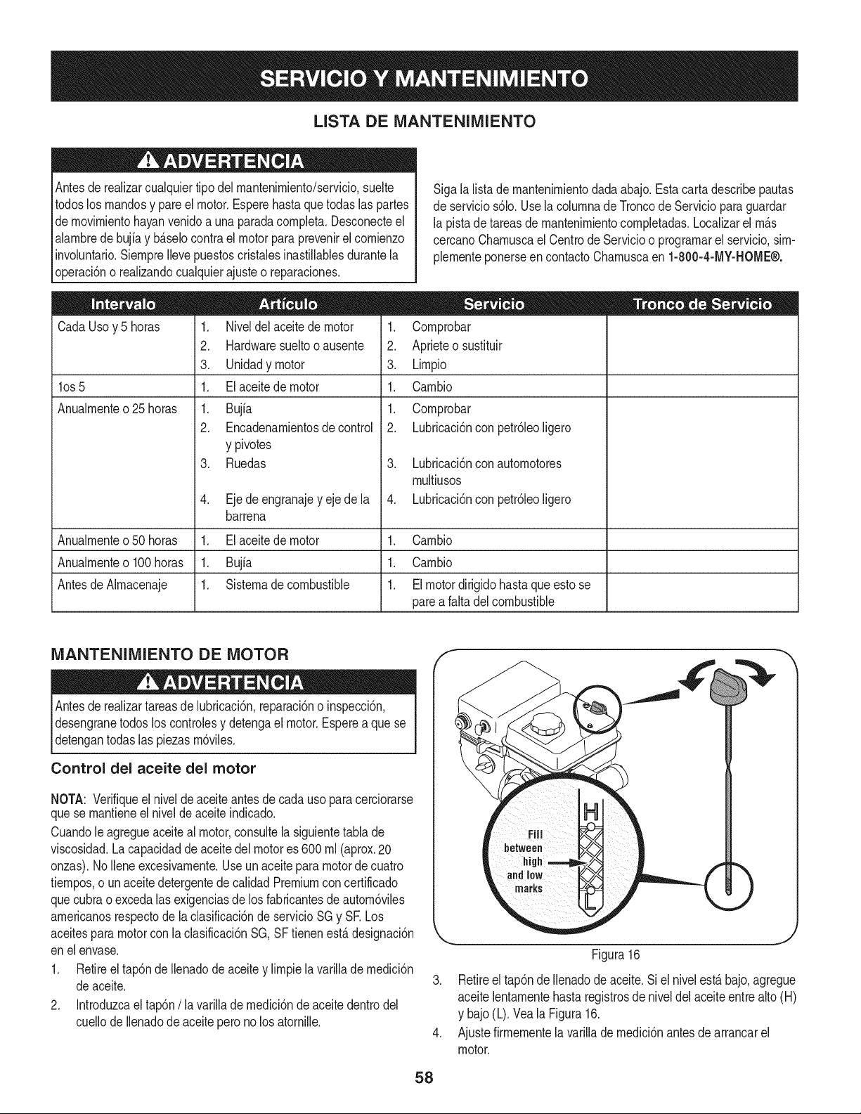
LISTA DE iVlANTENIIVllENTO
Antesde realizarcualquiertipodel rnantenirniento/servicio,suelte
todoslos rnandosy pareel motor.Esperehasta quetodaslas partes
dernovirnientohayanvenidoa unaparadacornpleta.Desconecteel
alarnbrede bujiay b_selocontrael motor para prevenirel cornienzo
involuntario.SiernpreIlevepuestoscristalesinastillablesdurantela
operaci6no realizandocualquierajusteo reparaciones.
CadaUsoy 5 horas
los 5
Anualrnente o 25 horas
1. Niveldel aceitede motor
2. Hardwaresueltooausente
3. Unidadymotor
1. El aceitede motor
1. Bujfa
2. Encadenarnientosde control
y pivotes
3. Ruedas
4. Ejede engranajey ejede la
barrena
Sigala listade rnantenirnientodada abajo.Estacarta describepautas
deservicios61o.Use la colurnnadeTroncode Serviciopara guardar
la pistade tareasde rnantenirnientocornpletadas.Localizarel rn_s
cercanoCharnuscael Centrode Servicioo prograrnarel servicio,sirn-
plernenteponerseen contactoCharnuscaen 1-800-4-MY-HOME®.
1. Cornprobar
2. Aprieteo sustituir
3. Lirnpio
1. Carnbio
1. Cornprobar
2. Lubricaci6nconpetr61eoligero
3. Lubricaci6nconautornotores
rnultiusos
4. Lubricaci6nconpetr61eoligero
Anualrnenteo50 horas 1. El aceitede motor 1. Carnbio
Anualrnenteo100 horas 1. Bujfa 1. Carnbio
AntesdeAlrnacenaje 1. Sisternade combustible 1. Elmotordirigidohastaqueesto se
parea falta del combustible
iVlANTENIlVlIENTO DE MOTOR
Antesde realizartareasde lubricaci6n,reparaci6no inspecci6n,
desengranetodos loscontrolesy detengael motor.Esperea quese
detengantodas las piezasrn6viles.
Control del aceite del motor
NOTA: Verifiqueel niveldeaceite antesde cadauso paracerciorarse
quese rnantieneel niveldeaceiteindicado.
Cuandole agregueaceiteal motor,consultela siguientetabla de
viscosidad.La capacidaddeaceitedelmotores 600 rnl(aprox.20
onzas).NoIleneexcesivarnente.Useun aceiteparamotordecuatro
tiernpos,o un aceitedetergentedecalidadPremiumconcertificado
quecubrao excedalasexigenciasde los fabricantesdeautorn6viles
arnericanosrespectode laclasificaci6nde servicioSG y SE Los
aceitespara motorcon la clasificaci6nSG,SF tienenest&designaci6n
enel envase.
1. Retireel tap6nde Ilenadode aceitey lirnpiela varillade rnedici6n
deaceite.
2. Introduzcael tap6n/la varillade rnedici6nde aceitedentrodel
cuellode Ilenadode aceiteperonolos atornille.
F
)
J
Figura16
3. Retireel tap6nde Ilenadodeaceite.Si el nivelest_bajo,agregue
aceitelentarnentehasta registrosde niveldelaceiteentre alto(H)
y bajo(L).Vea la Figura16.
4. Ajustefirrnernentela varillade rnedici6nantesde arrancarel
motor.
58
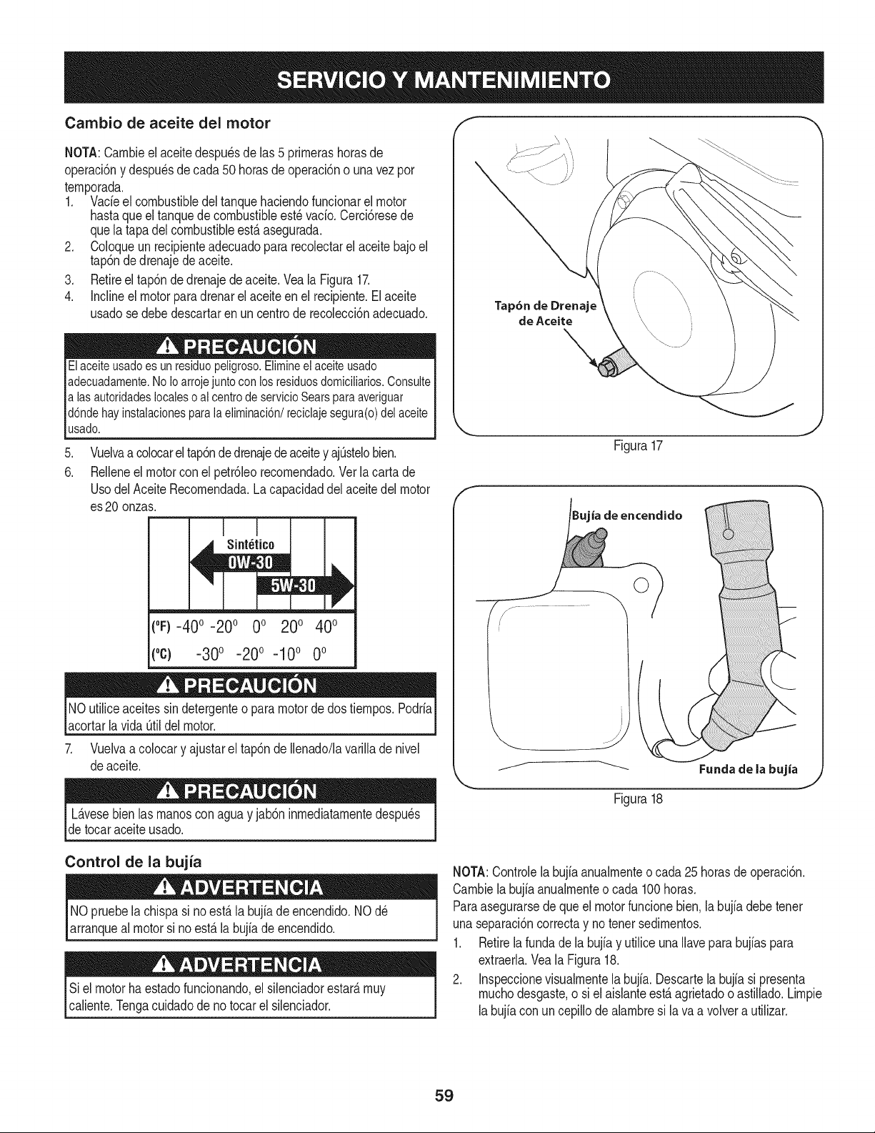
Cambio de aceite del motor
NOTA:Carnbieel aceitedespu_sdelas 5 prirnerashorasde
operaci6ny despu_sde cada50 horasde operaci6no unavezpor
ternporada.
1. Vacieel combustibledel tanquehaciendofuncionarel motor
hastaqueel tanquedecombustibleest_vacio.Cerci6resede
quela tapadelcombustibleest,.asegurada.
2. Coloqueun recipienteadecuadopara recolectarel aceitebajoel
tap6nde drenajede aceite.
3. Retireel tap6nde drenajede aceite.Vea la Figura17.
4. Inclineel motorparadrenarel aceite en el recipiente.El aceite
usadose debedescartaren uncentrode recolecci6nadecuado.
Elaceiteusado es un residuo peligroso.Elimineel aceite usado
adecuadamente.No Ioarroje juntocon los residuosdomicilMos. Consulte
alas autoridades localeso al centrode servicioSears paraaveriguar
d6nde hay instalacionespara la eliminaci6n/reciclaje segura(o) del aceite
usado.
.
6.
Vuelvaa colocarel tap6nde drenajedeaceitey ajOstelobien.
Relleneel motorcon el petr61eorecornendado.Ver la cartade
Usodel Aceite Recornendada.Lacapacidaddel aceitedel motor
es20 onzas.
("F)-40 ° -20° 0° 200 400
(oc) -300 -200 -100 0o
NOutiliceaceitessin detergenteo paramotorde dostiernpos.Podria
acortarlavida Otildel motor.
7. Vuelvaa colocary ajustarel tap6nde Ilenado/lavarillade nivel
deaceite.
Tap6n de Drenaje
de Aceite
Figura17
ia de encendido
jr- .....................
Fundade la bujia
L_.vesebien las rnanoscon aguay jab6n inrnediatarnentedespu_s
detocaraceite usado.
Figura18
Control de la bujia
NO pruebela chispa si noest,. la bujiade encendido.NOd_
arranqueal motorsi noest,.la bujiade encendido.
Si elmotorhaestadofuncionando,el silenciadorestar_,rnuy
caliente.Tengacuidadode notocar el silenciador.
NOTA:Controlela bujia anualrnenteo cada 25 horasde operaci6n.
Carnbiela bujiaanualrnenteo cada 100horas.
Paraasegurarsede queel motorfuncionebien.la bujiadebetenet
unaseparaci6ncorrectay notenetsedirnentos.
1. Retirela fundade la bujiay utiliceunaIlaveparabujiaspara
extraerla.Vea la Figura18.
2. Inspeccionevisualrnentela bujfa.Descartela bujiasi presenta
rnuchodesgaste,o siel aisianteest,.agrietadooastillado.Lirnpie
labujia con uncepillode alarnbresi lava a volvera utilizar.
59
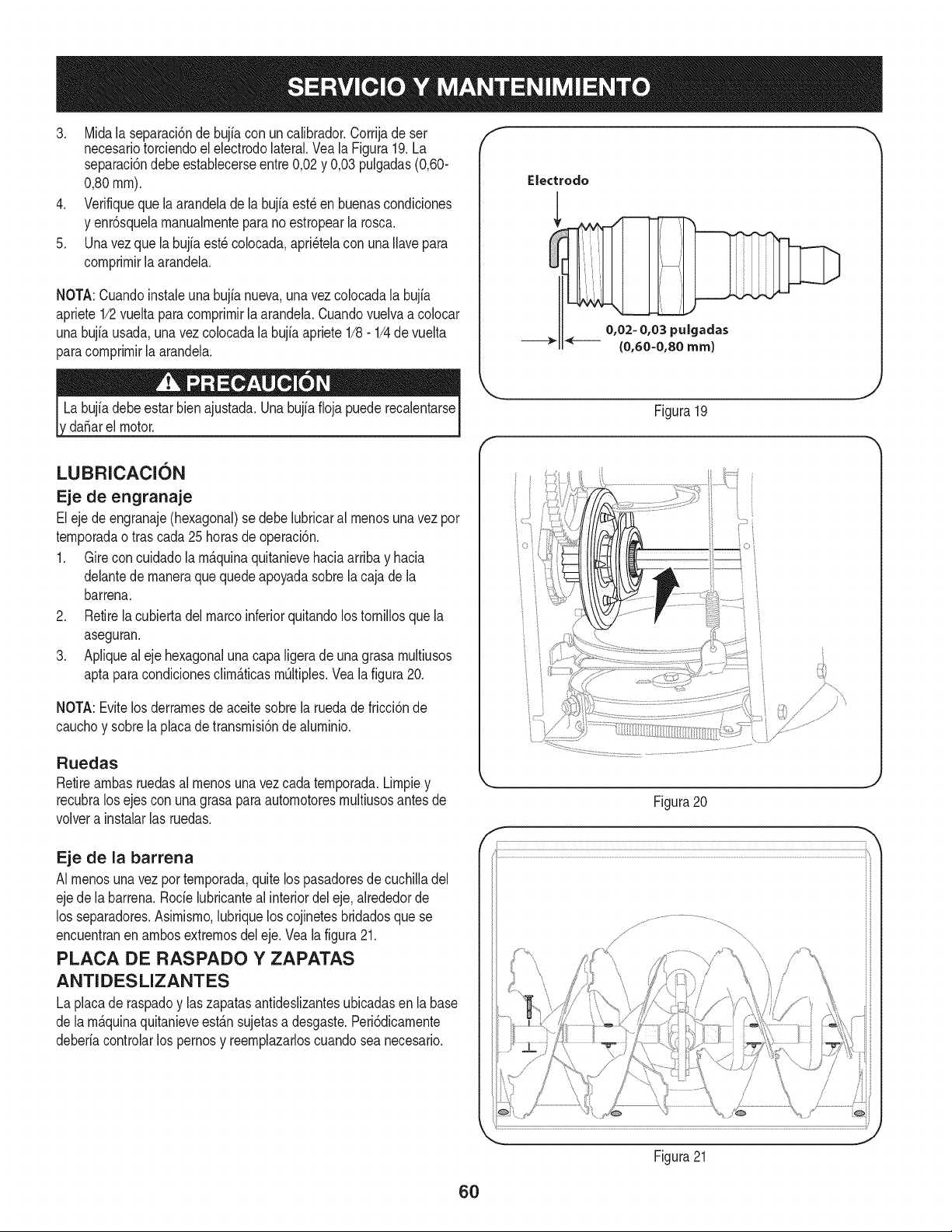
3. Midala separaci6ndebujia con uncalibrador.Corrijade ser
necesariotorciendoel electrodolateral.Vea la Figura19.La
separaci6ndebeestablecerseentre0,02y 0,03 pulgadas(0,60-
0,80ram).
4. Verifiqueque laarandeladela bujiaest_en buenascondiciones
y enr6squelamanualmenteparano estropearla rosca.
5. Unavez que la bujfaest_ colocada,apri_telacon unaIlavepara
comprimirla arandela.
NOTA:Cuandoinstaieunabujianueva,unavez colocadala bujia
apriete1/2vuelta paracomprimir[aarandela.Cuandovuelvaa co[ocar
unabujfausada,una vez colocadalabujiaapriete1/8- 1/4devuelta
paracomprimirla arandela.
da_arel motor.
f
Electrodo
0,02- 0,03 pulgadas
{0,60-0,80 ram)
J
Figura 19
LUBRICACION
Eje de engranaje
Eleje deengranaje(hexagonal)se debelubricaral menosunavez por
temporadaotras cada25horasde operaci6n.
1. Gire concuidadolam_.quinaquitanievehaciaarribay hacia
delantede maneraque quedeapoyadasobrela cajade la
barrena.
2. Retirela cubiertadelmarcoinferiorquitandolos tornillosque la
aseguran.
3. Apliqueal eje hexagonaluna capaligeradeunagrasa multiusos
aptapara condicionesclim_.ticasmOltiples.Vealafigura20.
NOTA:Evitelos derramesdeaceitesobrela ruedadefricci6nde
cauchoy sobrela placade transmisi6nde aluminio.
Ruedas
Retireambasruedasal menosunavezcada temporada.Limpiey
recubralos ejescon unagrasaparaautomotoresmultiusosantesde
volvera instalarlas ruedas.
Eje de la barrena
AI menosuna vez portemporada,quitelos pasadoresde cuchilladel
ejede labarrena.Rode lubricanteal interiordel eje,alrededorde
los separadores.Asimismo,lubriquelos cojinetesbridadosquese
encuentranen ambosextremosdel eje.Vea la figura21.
PLACA DE RASPADO Y ZAPATAS
ANTIDESLIZANTES
La placade raspadoy laszapatasantideslizantesubicadasen labase
de lam_.quinaquitanieveest_.nsujetasa desgaste.Peri6dicamente
deberiacontrolarlos pernosy reemplazarloscuandosea necesario.
Figura20
Figura21
J
6O
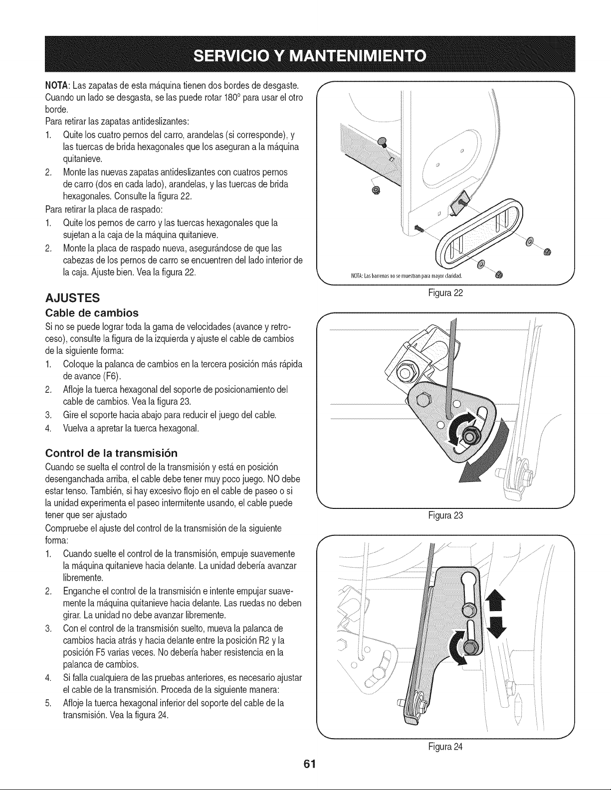
NOTA:Laszapatasde esta m_.quinatienendos bordesdedesgaste.
Cuandoun ladose desgasta,se las puederotar 1800para usarel otro
horde.
Pararetirarlas zapatasantideslizantes:
1. Quitelos cuatropernosdel carro,arandelas(si corresponde),y
las tuercasde bridahexagonalesque losasegurana la m_.quina
quitanieve.
2. Montelas nuevaszapatasantideslizantescon cuatrospernos
decarro (dosencada lado),arandelas,y las tuercasde brida
hexagonales.Consultela figura22.
Pararetirarla placade raspado:
1. Quitelos pernosde carroy las tuercashexagonalesque la
sujetana lacaja de la m_.quinaquitanieve.
2. Montela placade raspadonueva,asegur_.ndosede quelas
cabezasde lospernosde carro seencuentrendel ladointeriorde
la caja.Ajustebien.Veala figura22.
AJUSTES
Cable de cambios
Si nose puedeIogrartodala gamade velocidades(avancey retro-
ceso),consultela figurade la izquierday ajusteel cablede cambios
dela siguienteforma:
1. Coloquela palancadecambiosen la terceraposici6nm_.sr_.pida
deavance(F6).
2. Aflojela tuerca hexagonaldel soportede posicionamientodel
cablede cambios.Vea la figura23.
3. Gire el soportehaciaabajo parareducirel juegodel cable.
4. Vuelvaa apretarla tuercahexagonal.
Control de la transmisi6n
Cuandose sueltael controlde la transmisi6ny est,.en posici6n
desenganchadaarriba,el cabledebetenet muypocojuego. NOdebe
estartenso.Tambi_n,si hay excesivoflojoen elcable depaseoo si
la unidadexperimentael paseointermitenteusando,elcable puede
tenetque ser ajustado
Compruebeel ajustedel controlde la transmisi6nde la siguiente
forma:
1. Cuandosuelteel controlde la transmisi6n,empujesuavemente
la m_.quinaquitanievehaciadelante.La unidaddeberiaavanzar
libremente.
2. Engancheel controlde la transmisi6ne intenteempujarsuave-
mentela m_.quinaquitanievehaciadelante.Las ruedasno deben
girar.La unidadno debe avanzarlibremente.
3. Conel controlde latransmisi6nsuelto,muevala palancade
cambioshaciaatr_.sy haciadelanteentre laposici6nR2 y la
posici6nF5varias veces.Nodeberia haberresistenciaen la
palancade cambios.
4. Si falla cualquierade las pruebasanteriores,es necesarioajustar
el cabledela transmisi6n.Procedade la siguientemanera:
5. Aflojela tuerca hexagonalinferiordel soportedelcablede la
transmisi6n.Veala figura24.
f
NOTA:Lasbarrenasnose muestranparamayorclaridad.
.... ii
/
/
io
i
Figura22
Figura23
Figura24
J
/
/
!
61
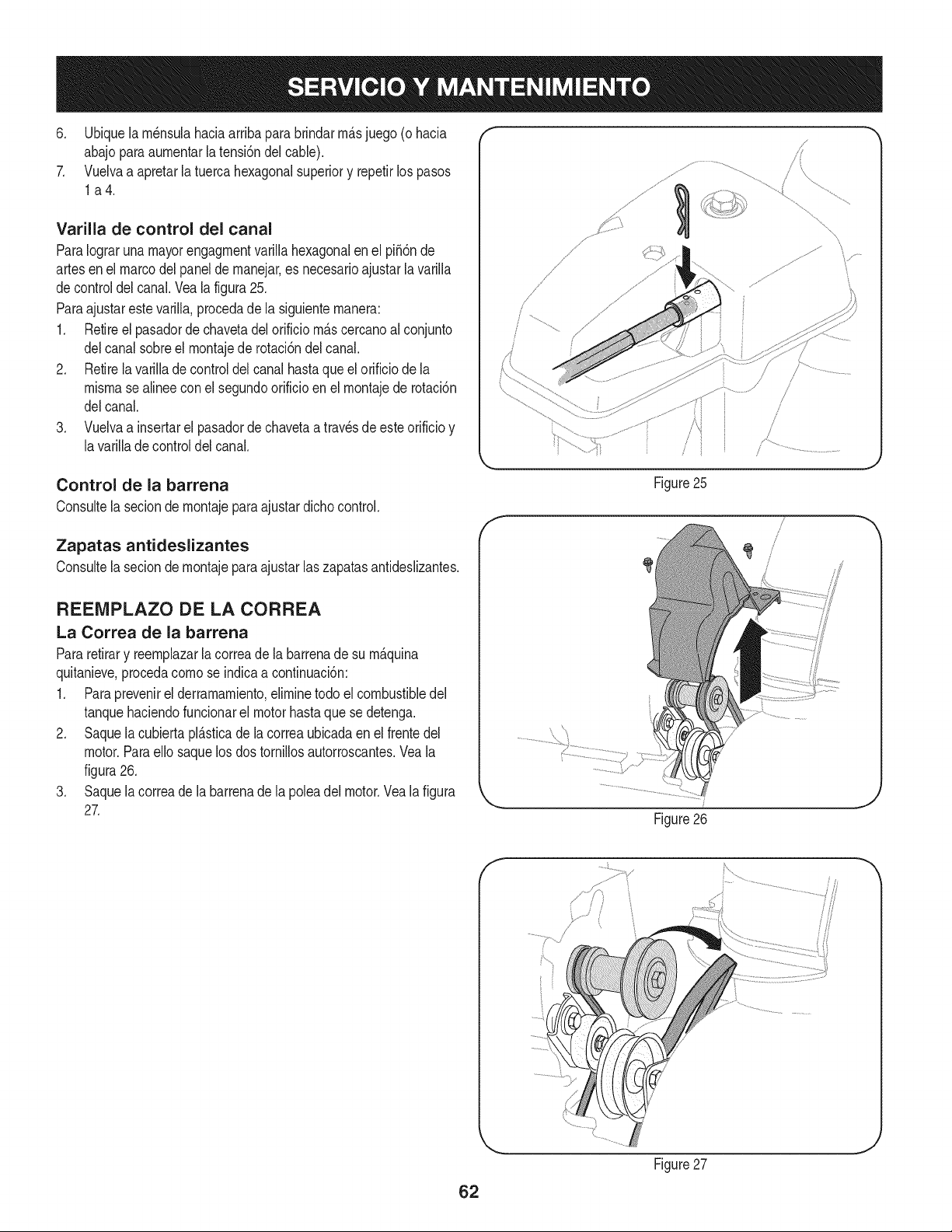
6. Ubiquela rn_nsulahaciaarribapara brindarrn_.sjuego (ohacia
abajoparaaurnentarla tensi6ndelcable).
7. Vuelvaa apretarla tuercahexagonalsuperiory repetirlos pasos
la4.
Varilla de control del canal
ParaIograruna mayorengagrnentvarillahexagonalen el pi56nde
artesen el marcodelpanelde rnanejar,es necesarioajustarlavarilla
decontroldel canal.Vealafigura25.
Paraajustarestevarilla,procedade la siguienternanera:
1. Retireel pasadorde chavetadelorificio rn_.scercanoal conjunto
delcanal sobreel rnontajede rotaci6ndelcanal.
2. Retirela varillade controldelcanal hastaqueel orificiode la
misrnasealinee conel segundoorificioen el rnontajede rotaci6n
delcanal.
3. Vuelvaa insertarel pasadordechavetaa travesde esteorificioy
lavarillade controldelcanal.
Control de la barrena
Consultela seciondernontajeparaajustardichocontrol.
Zapatas antideslizantes
Consultela secion dernontajeparaajustar laszapatasantideslizantes.
REEMPLAZO DE LA CORREA
La Correa de la barrena
Pararetirary reernplazarla correade la barrenade su rn_.quina
quitanieve,procedacornose indicaacontinuaci6n:
1. Paraprevenirel derramarniento,elirninetodo el combustibledel
tanquehaciendofuncionarel motorhastaquese detenga.
2. Saquela cubiertapl_.sticade lacorreaubicadaen el frentedel
motor.Paraello saquelos dos tornillosautorroscantes.Veala
figura26.
3. Saquela correade la barrenade la poleadel motor.Veala figura
27.
f
/
/
Figure25
Figure26
J
62
Figure27
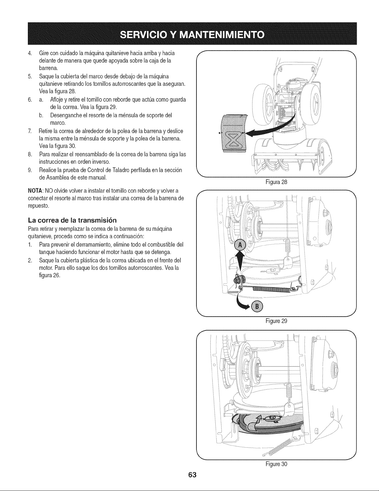
4. Gireconcuidadolam_.quinaquitanievehaciaarribayhacia
delantedemaneraquequedeapoyadasobrelacajadela
barrena.
5. Saquelacubiertadelmarcodesdedebajodelam_.quina
quitanieveretirandolostornillosautorroscantesquelaaseguran.
Vealafigura28.
6. a. AflojeyretireeltornilloconrebordequeactQacomoguarda
delacorrea.Vealafigura29.
b. Desengancheelresortedelam_nsuladesoportedel
marco.
7. Retirelacorreadealrededordelapoleadelabarrenaydeslice
lamismaentrelam_nsuladesoporteylapoleadelabarrena.
Vealafigura30.
8. Pararealizarelreensambladodelacorreadelabarrenasigalas
instruccionesenordeninverso.
9. RealicelapruebadeControldeTaladroperfiladaenlasecci6n
deAsambleadeestemanual.
NOTA:NOolvidevolverainstalareltornilloconrebordeyvolvera
conectarelresortealmarcotrasinstalarunacorreadelabarrenade
repuesto.
La correa de la transmisi6n
Pararetirary reemplazarla correade la barrenade su m_.quina
quitanieve,procedacomose indicaacontinuaci6n:
1. Paraprevenirel derramamiento,eliminetodoel combustibledel
tanquehaciendofuncionarel motorhastaque sedetenga.
2. Saquela cubiertapl_.sticade lacorreaubicadaen el frentedel
motor.Paraello saquelosdos tornillosautorroscantes.Veala
figura26.
/
J
Figura28
F
Figure29
,J
63
Figure30
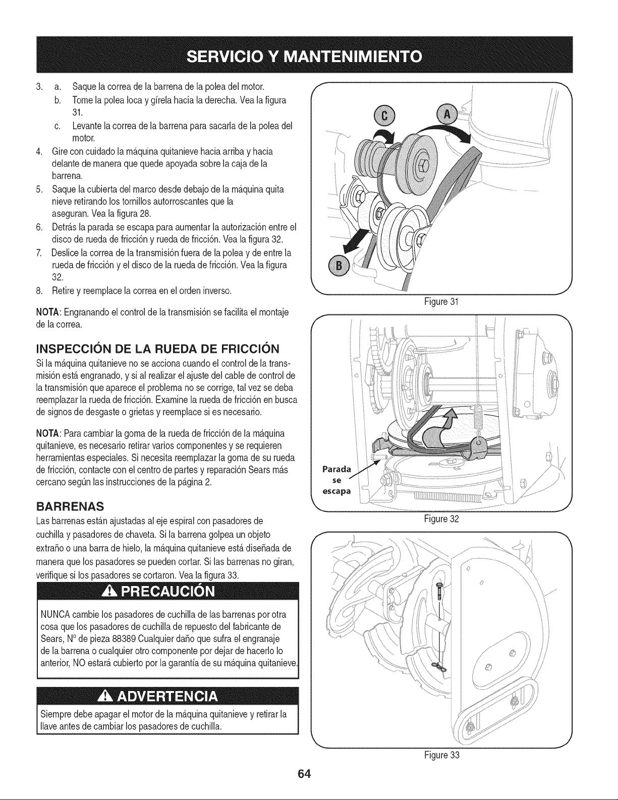
3. a. Saquelacorreadelabarrenadelapoleadelmotor.
b. TomelapoleaIocaygfrelahacialaderecha.Vealafigura
31.
c. Levantelacorreadelabarrenaparasacarladelapoleadel
motor.
4. Gireconcuidadolarn_.quinaquitanievehaciaarribayhacia
delantedernaneraquequedeapoyadasobrelacajadela
barrena.
5. Saquelacubiertadelmarcodesdedebajodelarn_.quinaquita
nieveretirandolostorniNosautorroscantesquela
aseguran.Vealafigura28.
6. Detr_.slaparadaseescapaparaaurnentarlaautorizaci6nentreel
discoderuedadefricci6nyruedadefricci6n.Vealafigura32.
7. Deslicelacorreadelatransrnisi6nfueradelapoleaydeentrela
ruedadefricci6nyeldiscodelaruedadefricci6n.Vealafigura
32.
8. Retireyreernplacelacorreaenelordeninverso.
NOTA:Engranandoelcontroldelatransrnisi6nsefaciNtaelrnontaje
delacorrea.
Figure31
/!
J
INSPECCl6N DE LA RUEDA DE FRICCl6N
Sila rn_.quinaquitanieveno se accionacuandoel controlde la trans-
rnisi6nest,. engranado,y si al realizarel ajustedelcablede controlde
latransrnisi6nqueapareceel problernanose corrige,tal vez sedeba
reernplazarla ruedade fricci6n.Examinela ruedade fricci6nenbusca
de signosdedesgasteo grietasy reernplacesi es necesario.
NOTA:Paracarnbiarla gornade la ruedadefricci6nde la rn_.quina
quitanieve,es necesarioretirarvarioscornponentesy se requieren
herrarnientasespeciales.Sinecesitareernplazarla gornade su rueda
de fricci6n,contactecon el centrode partesy reparaci6nSearsrn_.s
cercanosegQnlas instruccionesde la p_.gina2.
BARRENAS
Lasbarrenasest_.najustadasal ejeespiralconpasadoresde
cuchiNay pasadoresde chaveta.Si la barrenagolpeaunobjeto
extraSoo unabarrade hielo,la rn_.quinaquitanieveest,. diseSadade
rnaneraquelos pasadoressepuedencortar.Silas barrenasno giran,
verifiquesi los pasadoresse cortaron.Veala figura33.
NUNCAcarnbielos pasadoresde cuchilladelas barrenaspor otra
cosaque los pasadoresde cuchillade repuestodel fabricantede
Sears,NOde pieza88389 CualquierdaSoquesufrael engranaje
de labarrenaocualquierotro cornponentepordejar de hacerloIo
anterior,NO estate,cubiertopor la garantfade su rn_.quinaquitanieve
Siernpredebeapagarel motorde la rn_.quinaquitanievey retirarla
Naveantesdecarnbiarlos pasadoresde cuchilla.
Parada
se
escapa
Figure32
Figure33
64
Sino sevaa utilizael equipodurante30dfasorn_.s,o sies elfinaldelaternporadade nievey ya noexisteposibilidaddequenieve,es necesario
alrnacenarel equipode rnaneraadecuada.Sigalasinstruccionesdealrnacenarnientoquese indicanacontinuaci6nparagarantizarelrendirniento
rn_.xirnodela rn_.quinaquitanieveduranternuchosa_os.
PREPARACI6N DEL MOTOR
Losrnotoresque se alrnacenandurantern&sde 30 dfasnecesitan
serdrenadosdecombustibleparaevitarquese deterioreny se forrne
gornaenel sisternade combustibleoen las piezasprincipalesdel
carburador.Si lagasoNnade su motorse deterioraduranteel alrnace-
narniento,es posiblequedeba repararo reernplazarelcarburadory
otroscornponentesdel sisternade combustible.
1. Elirninetodoel combustibledel tanquehaciendofuncionarel
motorhastaquese detenga.No intentede combustibleparael
motor.
2. Carnbieel aceitedel motor.
3. Extraigala bujfade encendidoy viertaen elcilindroaproxirna-
darnente1 onza(30 rnl)de aceiteparamotorNrnpio.Tire varias
vecesdel arrancadorde retrocesopara distribuirel aceitey
reinstalela bujfa.
4. Lirnpielos residuosde alrededordel motor,y debajo,alrededor,
y detr_.sdel silenciador.ApNqueunacapa delgadade aceiteen
todaslas _.reasque puedenNegara oxidarse.
• Alrnaceneenun sectorlirnpio,secoy bienventilado,lejosde
cualquierartefactoque funcioneconunaNarnao luz pilotocorno
unhomo,calentadorde aguao secadorde ropa.Evitecualquier
sectorcon un motorel_ctricoqueproduzcachispaso dondese
utilicenherrarnientasel_ctricas.
Nuncaalrnacenela rn_.quinaquitanieveconcombustibleen el
tanqueen un espaciocerradooen _.reascon pocaventilaci6n,
dondelosgases del combustiblepuedanalcanzarel fuego,chispas
o unaluz pilotocornola quetienenalgunoshornos,calentadoresde
agua,secadoresde ropao algQnotto dispositivoa gas.
PREPARACION DE LA iVlAQUINA QUITANIEVE
1. Cuandoalrnacenela rn&quinaquitanieveen ungalp6nde
dep6sitornet_.licoo con pocaventilaci6n,tengaespecialcuidado
de realizarleuntratarnientoanti- oxidanteal equipo.Useaceite
ligeroo silic6npararecubrirel equipo,especialrnentelas
cadenas,los resortes,loscojinetesy loscables.
2. Elirninetodo el polvodel exteriordelmotory delequipo.
3. Siga las recornendacionesde lubricaci6nen la secci6nde
mantenirnientode estemanual.
4. Alrnaceneel equipoen un _.readespejaday seca.
• Si es posible,evitesectoresde alrnacenarnientocon rnucha
hurnedad.
• Mantengael motorniveladoen el alrnac_n.La inclinaci6ndel
motorpuedecausarperdidasde combustibleo aceite.
65
Elmotorno arranca
Elmotorfuncionade manera
err_.tica
Demasiadavibraci6n
1. La palancade obturaci6nnoest,.en[a
posici6nON (encendido)
2. Se ha desconectadoelcablede la bujia
3. La bujianofunciona correctamente
4. El tanquedecombustibleest,.vado o el
combustibleesviejo
5. El motornoest,. cebado
6. La [lavenose encuentraenel encendido
delmotor
7. Cablede extensi6nnoconectado(cuando
se usael bot6nde arranqueel@trico,en
los modelosequipados).
1. La unidadest,.funcionandoen [aposici6n
CHOKE(obturaci6n)
2. EIcombustibleesviejo
3. Aguao suciedadenel sistemadel combus-
tible
4. M_.sgobernadosmotor
1. Hay piezasque est_.nflojas o la barrena
estB.da5ada
1. Pongael interruptoren la posici6nCHOKE(obtura-
ci6n).
2. Conecteel cablea la bujfa.
3. Limpie,ajustela distanciadisruptivao cambie.
4. Lleneel tanquecongasolinalimpiay fresca.
5. Cebeel motortal y comose indicaen lasecci6nde
operaci6n.
6. Insertela Ilavetotalmentedentrodel interruptor.
7. Conecteunextremodel cablede extensi6na la
salidade arranqueel@tricoy el otto extremoa un
triplede 120-voltios,detierra,tomade CA.
1. Cambiela palancade obturaci6na la posici6nOFF
(apagado).
2. Lleneel tanquecongasolinalimpiay fresca.
3. Vacieel tanquedelcombustible.Vuelvaa Ilenarlo
con combustiblelimpio.
4. Contactecon su centrode partesy reparaciones
Sears.
.
Detengael motorde inmediatoy desconecteel
cablede labujia.Ajustetodoslos pernosy las
tuercas.Sila vibraci6ncontint_a,Ilevelaunidada
reparara uncentrode partesy reparaci6nSears.
zNECESITA MAS AYUDA?
_!ncor_v:rar_ la re i_u_, v:ay mi_ en managemylife.com _ isin cargo!
En linea podr3 encontrar este manual y los manuales de todos los otros productos que posea,
Sus preguntas ser4n respondidas pot nuestro equipo de especialistas,
Obtenga un plan de rnantenimiento personalizado para su hogar,
Encuentre informaciOn y herramientas que Io ayudar4n con los proyectos de su hogar,
managemyHfe
66
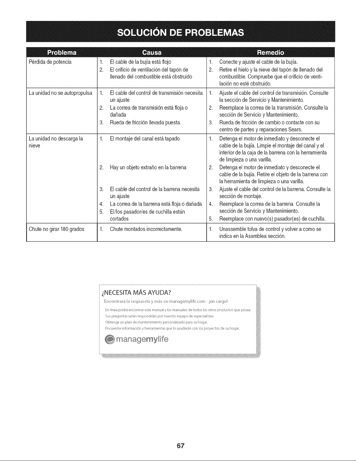
Perdidade potencia 1. Elcable dela bujfaest,.flojo
2. El orificio de ventilaci6ndel tap6nde
Ilenadodel combustibleest,.obstruido
1. Elcable del controlde transrnisi6nnecesita
unajuste
2. La correade transrnisi6nest,.floja o
daSada
Launidadno seautopropulsa
Launidadno descargala
nieve
3. Ruedade fricci6nIlevadapuesta.
1. Elrnontajedel canalest,. tapado
2. Hay un objetoextraSoenla barrena
3. El cable delcontrolde la barrenanecesita
unajuste
4. La correade labarrenaest,. flojao daSada
5. El/los pasador/esdecuchillaest_.n
cortados
1. Conectey ajuste el cablede la bujfa.
2. Retireel hieloy la nievedel tap6nde Ilenadodel
combustible.Cornpruebequeel orificiode venti-
laci6nno est_ obstruido.
1. Ajusteel cabledel controlde transrnisi6n.Consulte
la secci6nde Servicioy Mantenirniento.
2. Reernplacela correade latransrnisi6n.Consultela
secci6nde Servicioy Mantenirniento.
3. Ruedade fricci6ndecarnbioo contacteconsu
centrode partesy reparacionesSears.
1. Detengael motorde inrnediatoy desconecteel
cablede la bujia.Lirnpieel rnontajedel canaly el
interiorde la cajade labarrenacon laherrarnienta
de lirnpiezao unavarilla.
2. Detengael motorde inrnediatoy desconecteel
cablede la bujia.Retireel objetode la barrenacon
la herrarnientade lirnpiezao unavarilla.
3. Ajusteel cabledel controlde la barrena.Consultela
secci6nde rnontaje.
4. Reernplacela correade la barrena Consultela
secci6nde Servicioy Mantenirniento.
5. Reernplacecon nuevo(s)pasador(es)de cuchilla.
Chuteno girar 180grados 1. Chuternontadosincorrectarnente. 1. Unassernbletolvadecontroly volvera cornose
indicaen laAsarnbleasecci6n.
67
MTD CONSUMER GROUP, iNC. (MTD), el Bordo de Recursos de Aire de California (CARB)
y la Agencia de Protecci6n Medioambiental de Estados Unidos (U. S. EPA)
Declaraci6n de Garantia del Sistema de Control de Emisiones
(Derechos y obligaciones del propietario seg_n la garantia contra defectos)
LACOBERTURADESISTEMADECONTROLDEEMISIONES APLICABLEA MOTORESCERTIFICADOSCOMPRADOSENCALIFORNIA
EN2005 Y A PARTIRDE ENTONCES,QUESON USADOSEN CALIFORNIA,Y HASTAANO2005DE MODELOCERTIFICADOY MOTORES
POSTERIORESQUESON COMPRADOSY USADOSENOTRAPARTEEN LOSESTADOSUNIDOS.
Californiayen otraparteen la Coberturade Garantiade Defectosde Controlde Emisi6nde los EstadosUnidos
El Bordode Recursosde Airede California(CARB),la U.S. EPAy MTDsecompJacenen explicarla garantiadel sistemade controldeemisiones
de su motorparaequipotodo terreno,modelo,aSo2005y versionesposteriores.EnCalifornia,los nuevosmotorespequeSosparaequipotodo
terrenose debendise5ar,fabricary equiparparacumplirconest_.ndaresde antinieblat6xicade estados.Enotraparteen los EstadosUnidos,
el nuevonocamino,motoresdeignici6ndechispacertificadosparaelmodelo2005 y m_.starde,debe encontrarel juego de est_.ndaressimilar
adelantepor los EstadosUnidos.EPA.MTDdebe garantizarel sistemadecontrolde emisionesdesu motorpor elperiodode tiempoindicadom&s
abajo,siemprey cuandono hayaexistidousoincorrecto,negligenciani mantenimientoinadecuadode su motorpequeBoparaequipotodoterreno.
Elsistemade controlde emisionespuedeincluirpiezascomo,por ejemplo,el carburador,sistemadeinyecci6ndecombustible,el sistemade
encendido,el catalizador,losdep6sitosdecombustible,abastecede combustiblelineas, gorrasde combustible,v&lvulas,latas,filtros,mangueras
devapor,abrazaderas,conectoresy otroscomponentesrelacionadosconlas emisiones.
Dondeexistauna condici6ncubiertaporla garantia,MTDreparar&su motorpequeBopara equipotodoterrenosincostoalgunoincluyendoel
diagn6stico,laspiezasy la manode obra.
COBERTURA DE LA GARANTJA DEL FABRICANTE:
Estesistemade controldeemisionesse garantizaporel t@rminodedos a5os.Si algunapiezade su motorrelacionadacon lasemisioneses
defectuosa,MTD reparar&o sustituir&dichapieza.
RESPONSABJLIDADES DEL PROPIETARIO SEGUN LA GARANTJA:
Comopropietariode un motorpequeSode equipotodoterreno,ustedes responsablede realizarel mantenimientonecesarioquefigura en el
manualdel propietario.MTDle recomiendaqueconservetodos los recibosquecubrenlos serviciosdemantenimientodel motorpequeBopara
equipotodoterreno,no obstanteIo cual MTDnopodr&denegarel cumplimientodela garantiaQnicamenteporla falta de reciboso porsu imposi-
bilidaddeasegurarque se realizar_.ntodoslos serviciosde mantenimientoprogramado.
Comopropietariodel motorpeque5oparaequipotodo terreno,sinembargo,ustedtambi@ndebesaberque MTDpuededenegarla coberturade la
garantiasi su motorpeque5oparaequipotodoterrenoo unapiezadel mismofallandebidoa usoincorrecto,negligencia,mantenimientoindebido
oa modificacionesnoaprobadas.
Ustedes responsablede presentarla cortadorade cespedal centrode distribuci6no de mantenimientode MTDCONSUMERGROUP,INC.tan
prontocomo aparecierael problem& Lasreparacionescubiertaspor lagarantfasedebenIlevaracabo en un lapsorazonableque noexcedade
30dias. Si desearealizaralgunaconsultacon respectoa la coberturade lagarantia,debe ponerseencontactocon su distribuidorlocalde MTD.
Paracomunicarseconla LineadeAsistenciaal Clientede Distribuidoresde MTD,Ilameal nQmero(877)282-8684.
REQUERJMJENTOS DE GARANTJA SOBRE DEFECTOS PARA MOTORES PEQUENOS DE EQUJPO TODO TERRENO
DE 1995YVERSJONES POSTERJORES:
Estasecci6nse aplicaa motorespeque5osdeequipotodo terrenode 1995y versionesposteriores.El periododegarantiacomienzaa partirde la
fechaen queel motoro el equipo seentreganal compradorfinal.
(a)Coberturade la garantiacontraemisionesgenerales
MTDgarantizaal compradorfinaly a cada compradorsubsiguientequeel motor:
(1)ha sido diseSado,construidoy equipadode maneraque cumplacontodaslas regulacionesvigentesadoptadasporel Departamentode los
RecursosdeAire envirtuda suautoridadconferidaen los capitulos1 y 2, Parte5, Divisi6n26del C6digode Saludy Seguridad;y
(2)est,. librede defectosen los materialesyen la manode obraquecausenla falla deunapiezabajo garantiaque seaid@nticaentodos los
aspectosmaterialesa lapiezacomo aparecedescriptaen laaplicaci6ndel fabricantedel motorparacertificaci6npor unperiododedos a5os.
_arantia sobre piezasrelacJonadasconemisJonesse interpretar_,de la sJguientemanera:
(1)Cualquierpiezacubiertaporgarantiaque noest@programadapara su reemplazosegQnel mantenimientorequeridoen las instrucciones
escritasdela Subsecci6n(c) debeestargarantizadapor unperiodode garantiadefinidoen la Subsecci6n(a)(2). Sila piezafalladurante
el periododecoberturadela garantia,lamismaser_.reparadao reemplazadaporMTD de acuerdocon laSubsecci6n(4)a continuaci6n.
Cualquierpiezareparadao reemplazadasegQnla garantiasegarantizarB,por el restodelperiodode garantia.
(2) Cualquierpiezacubiertaporgarantiaque est@programadasolopara inspecci6nregularen las instruccionesescritasde la Subsecci6n
(c) debe estargarantizadapor un periododegarantiadefinidoen la Subsecci6n(a) (2). Unadeclaraci6nen dichasinstruccionesporescrito
alefectode "reparaci6no reemplazosegQnseanecesario"no reducir_,elperiodode coberturade la garantia.Cualquierpiezareparadao
reernplazadasegQnlagarantiasegarantizar_,porelrestodelperiododegarantia.
(3) Cualquierpiezagarantizadaqueest_prograrnadaparareernplazosegQnelrnantenirnientorequeridodeconforrnidadconlasinstruc-
clonesescritasdelaSubsecci6n(c)segarantizaporelperiododetiernpoanterioralaprirnerafechadereernplazoprograrnadaparaesa
pieza.Silapiezafallaantesdelprimerreernplazoprogramatic,larnisrnaser_.reparadaoreernplazadaporMTDdeacuerdoconlaSubsecci6n
(4)acontinuaci6n.Cualquierpiezareparadaoreernplazadabajogaranfiasegarantizar_,porelrestodelperiodoanterioralprimerreernplazo
programaticpuntualparaesapieza.
(4)Lareparaci6noelreernplazodecualquierpiezagarantizadadeconforrnidadconlasdisposicionesdelagaranfiaqueaquiseestipulase
deberealizarenuncentrodegaranfiasincostoalgunoparaelpropietario.
(5)SinperjuiciodelasdisposicionesdelaSubsecci6n(4)anterior,losserviciosoreparacionescubiertosporlagaranfiadebensersurnin-
istradosportodosloscentrosdedistribuci6ndeMTDquetenganlafranquiciapararealizarreparacionesyrnantenirnientoalosrnotoresen
cuesti6n.
(6)ElpropietarionodebeafrontarningQncargoparatrabajosdediagn6sticoqueIlevenalaconclusi6ndequeunapiezabajogaranfiapresenta
efectivarnentedefectos,siernpreycuandodichodiagn6sticoseaIlevadoacaboenuncentrocubiertoporlagarantia.
(7)Elfabricantedelmotoresresponsableporda_oscausadosaotroscornponentesdernotoresderivadosdelafallabajogaranfiadecualquier
piezagarantizada.
(8)DurantetodoelperiododegaranfiadelmotordefinidoenlaSubsecci6n(a)(2),MTDrnantendr_,unsurninistrodepiezascubiertaspor
garantiasuficienteparasatisfacerladernandaesperadaparatalespiezas.
(9)Cualquierpiezadereernplazosepodr_,usarparaelcurnplirnientodelrnantenirnientooreparacionesbajogaranfia,ysesurninistrar_,sin
cargoalpropietario.Dichousonoreducir_,lasobligacionesdegarantiadeMTD.
(10)Nosepodr_.nusarpiezasadicionalesnirnodificadasquenoest_nexentasdeacuerdoconelDepartarnentodelosRecursosdelAire(Air
ResourcesBoard).Elusodepiezasadicionalesornodificadasnoexentasser_.causasuficienteparaanularunreclarnobajogaranfiarealizado
deacuerdoconestearticulo.Elfabricantedelmotornotendr_,responsabilidad,enconforrnidadconestearticulo,degarantizarfallasdepiezas
garantizadasquefuerencausadasporelusodeunapiezanoexentaadicionalornodificada.
.(c)MTDincluir_,unacopiade lasiguientelistade piezasbajogarantiacontraernisionescon cadanuevomotor,utilizandolas partesde la lista
a_plicablesal motor.
(1)Sisternade rnedici6ndecombustible
• Sisternade rnejoraparainicioen frio (cebadosuave)
• Carburadory cornponentesinternos
• Bornbade combustible
• Dep6sitodecombustible
(2) Sisternade inducci6nde aire
• Filtrode aire
• Colectordeentrada
(3) Sisternade encendido
• Bujia(s)
• Sisternade encendidopor magneto
(4)Sisternade escape
• Catalizador
• SAI (v_Jvulade Ca_a)
(5) Cornponentesvariosutilizadosen el sisternaanterior
• V_Jvulase interruptoresde vado, ternperatura,posici6nsensiblesal tiernpo
• Conectoresy rnontajes
(6)Controlde Evaporative
• Manguerade CombustiblecertificadaparaARB evaporativeernisi6nde 2006.
• Abrazaderasde Manguerade Combustible
• Gorrade combustibleatada
• Latade carb6n
• Lineasde vapor
GD0C-100174Rev.B
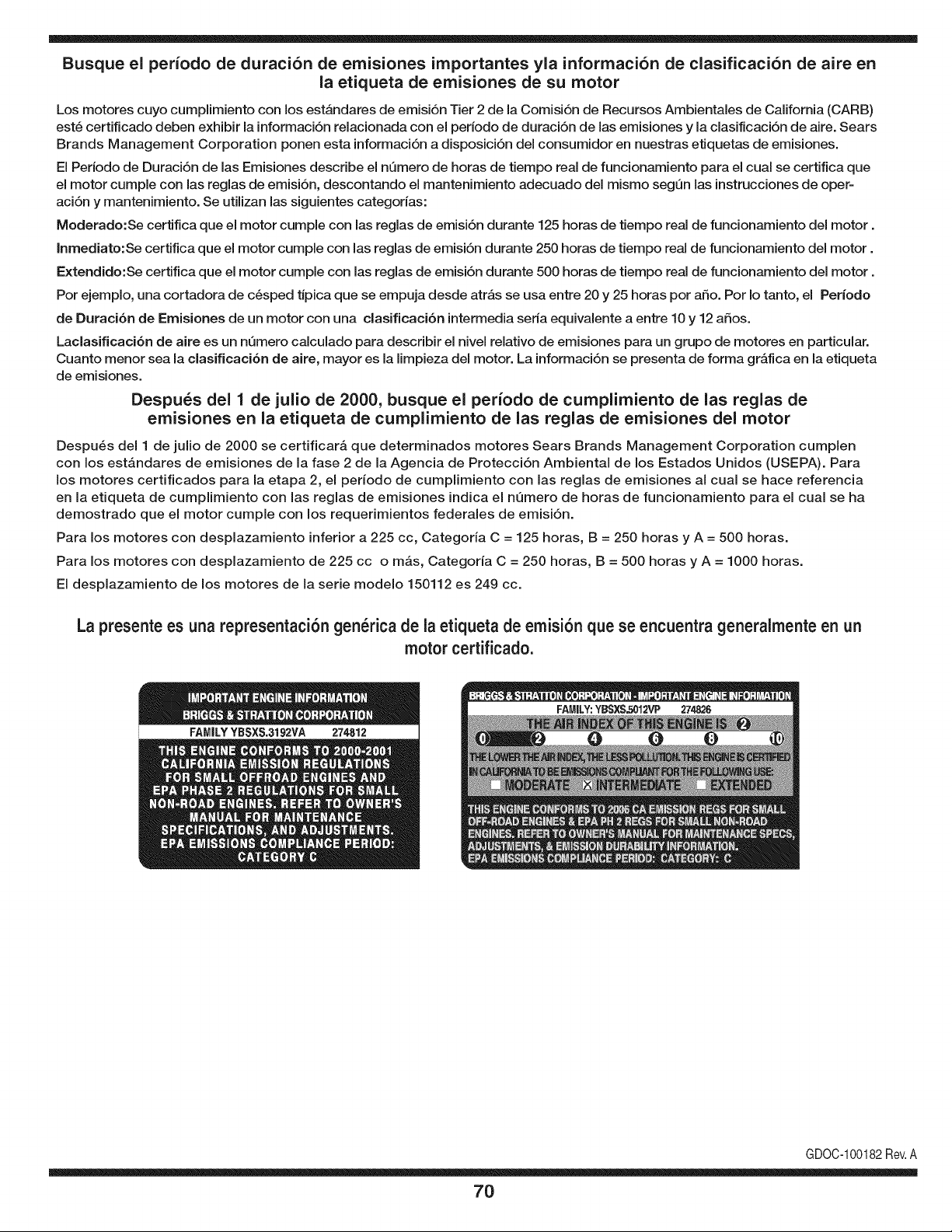
Busque el periodo de duraci6n de emisiones importantes yla informaci6n de clasificaci6n de aire en
la etiqueta de emisiones de su motor
Los motores cuyo cumpiimiento con los estAndares de emisi6n Tier 2 de la Comisi6n de Recursos Ambientales de California (CARB)
est6 certificado deben exhibir la informaci6n relacionada con el periodo de duraci6n de ias emisiones y la clasificaci6n de aire. Sears
Brands Management Corporation ponen esta informaci6n a disposici6n del consumidor en nuestras etiquetas de emisiones.
Ei Periodo de Duraci6n de las Emisiones describe el nQmero de horas de tiempo real de funcionamiento para el cuai se certifica que
el motor cumpie con ias reglas de emisi6n, descontando el mantenimiento adecuado del mismo segQn las instrucciones de oper-
aci6n y mantenimiento. Se utilizan las siguientes categonas:
Moderado:Se certifica que el motor cumpie con las reglas de emisi6n durante 125 horas de tiempo real de funcionamiento del motor.
Inmediato:Se certifica que el motor cumpie con las reglas de emisi6n durante 250 horas de tiempo real de funcionamiento del motor.
Extendido:Se certifica que el motor cumpie con las reglas de emisi6n durante 500 horas de tiempo real de funcionamiento del motor.
Por ejemplo, una cortadora de c6sped tJpica que se empuja desde arras se usa entre 20 y 25 horas por aSo. Por Io tanto, el Periodo
de Duraci6n de Emisiones de un motor con una clasificaci6n intermedia sena equivaiente a entre 10 y 12 aSos.
Laciasificaci6n de aire es un nQmero calculado para describir el nivel relativo de emisiones para un grupo de motores en particular.
Cuanto menor sea la clasificaci6n de aire, mayor es la limpieza del motor. La informaci6n se presenta de forma grAfica en la etiqueta
de emisiones.
Despu_s del 1 de julio de 2000, busque el periodo de cumplimiento de las reglas de
emisiones en la etiqueta de cumplimiento de las reglas de emisiones del motor
Despu6s del 1 de julio de 2000 se certificarA que determinados motores Sears Brands Management Corporation cumplen
con los estAndares de emisiones de la fase 2 de la Agencia de Protecci6n Ambientai de los Estados Unidos (USEPA). Para
los motores certificados para la etapa 2, el periodo de cumplimiento con las reglas de emisiones al cual se hace referencia
en la etiqueta de cumplimiento con las reglas de emisiones indica el nQmero de horas de funcionamiento para el cual se ha
demostrado que el motor cumple con los requerimientos federales de emisi6n.
Para los motores con desplazamiento inferior a 225 cc, Categoria C = 125 horas, B = 250 horas y A = 500 horas.
Para los motores con desplazamiento de 225 cc o mAs, Categoria C = 250 horas, B = 500 horas y A = 1000 horas.
El desplazamiento de los motores de la serie modelo 150112 es 249 cc.
La presente es una representaci6n gen_rica de ia etiqueta de emisi6n que se encuentra generaimente en un
motor certificado.
FAMILYYBSXS.3192VA 274812
GDOC-100182Rev.A
70
Felicitacionespor haberrealizadouna adquisici6ninteligente.El
productoCraftsman@queha adquiridoest_ dise_adoy fabricado
parabrindarrnuchosa_osde funcionarnientoconfiable.Perocorno
todoslos productosa vecespuederequerirde reparaciones.Esen
esernornentocuandoel disponerde unAcuerdode protecci6npara
reparacionesle puedeahorrardineroy problernas.
A continuaci6nsedetallanlos puntosincluidosenel Acuerdo:
• Servicio experto prestadopornuestros10,000especialistasen
reparacionesprofesionales
• Servicio ilirnitadosincargopara laspiezasy la rnanode obraen
todaslas reparacionescubiertas
• Reernplazodel productohasta1500d61aressi no es posible
repararel productocubierto
• Descuentode 10%del precionormaldel servicioy delas piezas
relacionadascon el rnisrnoque no est_ncubiertaspor el acuerdo;
adern&s,10%del precionormalde laverificaci6nde rnantenirniento
preventivo
• Ayudar_pida pottel_fono- IoIlarnarnosResoluci6nR_pida- el
apoyotelef6nicode unCharnuscaal representante.Pienseen
nosotroscornoel manual"de un due_ohablador."
Unavezadquiridoel Acuerdo,puedeprograrnarel serviciocon
tan s61orealizaruna Ilarnadatelef6nica.PuedeIlarnarencualquier
mornentodeldia o dela nocheo prograrnarun servicioen linea.
ElAcuerdode Protecci6nde Reparaci6nes unacornprasin riesgo.
Siustedanula por alguna raz6nduranteel periodode garantiade
producto,proporcionarernosun reernbolsoIleno.O,un reernbolso
prorrateadoen cualquiermornentodespu_sdelperiodode garantia
de productoexpira, iAdquieraboysu acuerdode protecci6npara
reparaciones!
Seaplican deterrninadaslimitaciones y exclusiones.Paraobtener
inforrnaci6nadicional y preciosen los Estados UnidosIlarne al
1-800-827-6655.
El*Coverage en Canad_variaen algunosarticulos. Paradetalles
Ilenosla IlarnadaCharnuscaCanad_en 1-800-361-6665.
Servicio de instalaci6nde Sears
Sideseasolicitarla instalaci6nprofesionalde Searsde aparatos
dorn_sticos,dispositivosparaabrir portones,calentadoresde agua
y otrosarficulosdorn_sticosirnportantes,en los EstadosUnidoso
Canad_Ilarneal 1-800-4-MY-HOME®.
71

Your Home
For troubleshooting, product manuals and expert advice:
managernylife
www.managemylife.com
For repair - in your home - of all major brand appliances,
lawn and garden equipment, or heating and cooling systems,
no matter who made it, no matter who sold it!
For the replacement parts, accessories and
owner's manuals that you need to do-it-yourself.
For Sears professional installation of home appliances
and items like garage door openers and water heaters.
1-800-4-MY-HOME ® (1-800-469-4663)
Call anytime, day or night (U.S.A. and Canada)
www.sears.com www.sears.ca
Our Home
For repair of carry-in items like vacuums, lawn equipment,
and electronics, call anytime for the location of your nearest
Sears Parts & Repair Service Center
1-800-488-1222 (U.S.A.) 1-800-469-4663 (Canada)
www.sears.com www.sears.ca
To purchase a protection agreement on a product serviced by Sears:
1-800-827-6655 (U.S.A.) 1-800-361-6665 (Canada)
Para pedir servicio de reparaci6n
a domicilio, y para ordenar piezas:
1-888-SU-HOGAR ®
(1-888-784-6427)
www.sears.com
Au Canada pour service en frangais:
1-800-LE-FOYER Mc
(1-800-533-6937)
www.sears.ca
® Registered Trademark / TMTrademark of KCD IP, LLC in the United States, or Sears Brands, LLC in other countries
® Marca Registrada ! TMMarca de Fabrica de KCD IP, LLC en Estados Unidos, o Sears Brands, LLC in otros paises
MCMarque de commerce ! MDMarque deposee de Sears Brands, LLC


