m PERSONAL INJURY WARNING
DO NOT USE these products as safety or emergency stop
devices or in any other application where failure of the
product could result in personal injury.
Failure to comply with these instructions could result in
death or serious injury.
, CAUTION
SWITCH DAMAGE
• Wiring must be rated to meet or exceed circuitry
requirements.
• Connecting circuitry must not exceed switch rating.
• Wiring connections must be properly secured.
• Do not exceed recommended soldering time or
temperature.
• Do not contact switch housing with soldering device.
• Do not exceed recommended mounting screw tightening
torques.
• Discontinue use if switch has been damaged or cover
removed.
• Do not apply side loads to actuator or exceed specified
travel limits.
• Do not operate or store in areas where corrosive gases
such as hydrogen sulfide are present.
Failure to comply with these instructions could result in
death or serious injury.
m DANGER
IMPROPER USE
DO NOT USE In hazardous environments where flammable
or explosive gases or liquids such as gasoline or thinners, etc.,
are present.
Failure to comply with these instructions could result in
death or serious injury.
GENERAL INFORMATION
MICRO SWITCH Original Technology V19 Series Basic Switches
are precision snap-action contact mechanisms enclosed in
plastic cases. Switch actuation triggers the mechanical closure
of the switch’s contacts. A small amount of arcing between
the contacts during contact closure occurs during normal
operation. In order to obtain desired switch performance, the
switch must be chosen based on the mechanical, electrical,
and environmental conditions of the application.
Do not use this product in an application where water or dust is
prevalent. The environmental degree of protection for the V19
Series is IP00. Honeywell offers a watertight switch in a similar
package, the V15W.
TABLE 1. MOUNTING INFORMATION
Mounting
hole size
Screw type* Screw size
Tightening
Torque (max.)
3,1 mm
Flat fillister
head
3 mm
4,5 kg-cm
[3.9 in-lb]
2,9 mm
(K option)
Flat fillister
head
#4
4,5 kg-cm
[3.9 in-lb]
*To prevent loosening of screws, use spring washers under
screw heads and thread lock adhesive.
• Turn OFF the power supply before mounting or removing
the switch, wiring, or performing maintenance or
inspection. Failure to do so may result in electric shock.
• Mount the switch onto a flat surface. Mounting on an
uneven surface may cause deformation of the switch,
resulting in faulty operation or damage.
• Use an operating device with low frictional resistance and
of a shape that will not interfere with the plunger otherwise
the plunger may be damaged.
• Position the operating device perpendicular to the
actuator/pushbutton to prevent side loading of the switch
actuator or pushbutton.
• Position the operating device so that no force is applied
to the pushbutton/actuator when the switch is in the free
position.
• The operating device should be positioned so that when
the switch is in the operating position it should move the
actuator no less than 70% of the total travel. Setting the
travel position so that less than 70% of the total travel is
used may cause poor contact or welding conditions due to
an insufficient contact switching force.
• The operating device should never force the actuator/
pushbutton to exceed the total travel position.
WIRING INFORMATION
• Connect wires firmly to terminals.
• Replace wires that have damaged insulation.
• Use properly sized spade terminals.
• Use wire rated for the application’s electrical load and
application’s temperature.
• Provide strain relief when a potential exists for forces to be
transferred from the lead wires to the switch terminals.
INSTALLATION INSTRUCTIONS FOR THE
MICRO SWITCH ORIGINAL TECHNOLOGY
BASIC SWITCH,
V19 SERIES SWITCHES
32348648
Issue B
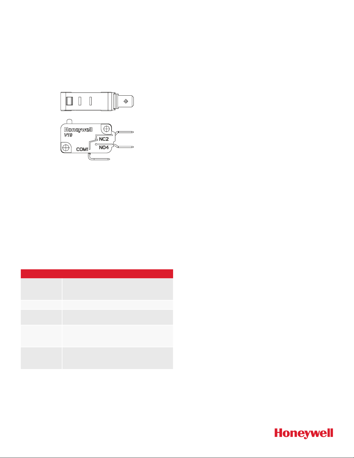
CIRCUIT INFORMATION
A circuit diagram is included on the switch case labeling each
of the terminals. The normal position corresponds to the switch
plunger in its released position.
SOLDERING GUIDELINES
When hand soldering the switch’s terminals, do not exceed
five seconds at 350°C [662°F]. Contacting the switch housing
with the soldering device may damage the switch housing.
Solder joints must not be moved for at least one minute after
soldering.
Do not try to clean the switch with a solvent or similar
substance after the soldering process.
ENVIRONMENTAL OPERATING
CHARACTERISTICS
TABLE 2. SPECIFICATIONS
Operating
temperature
range
“S” Grade: 25°C to 85°C [13°F to 185°F]
“T” Grade: 25°C to 125°C [13°F to 257°F]
Humidity Validated to 240 hours at 40°C, 95 %RH
Rate of
actuation
0,1 mm/s to 1000 mm/s
Operating
frequency
(electrical)
25 operations/minute max.
Operating
frequency
(mechanical)
60 operations/minute max.
MICRO SWITCH ORIGINAL TECHNOLOGY BASIC SWITCH,
V19 SERIES SWITCHES
Issue B
32348648
WARRANTY/REMEDY
Honeywell warrants goods of its manufacture as being free of
defective materials and faulty workmanship during the appli-
cable warranty period. Honeywell’s standard product warranty
applies unless agreed to otherwise by Honeywell in writing;
please refer to your order acknowledgement or consult your
local sales office for specific warranty details. If warranted
goods are returned to Honeywell during the period of coverage,
Honeywell will repair or replace, at its option, without charge
those items that Honeywell, in its sole discretion, finds defec-
tive. The foregoing is buyer’s sole remedy and is in lieu of all
other warranties, expressed or implied, including those of
merchantability and fitness for a particular purpose. In no
event shall Honeywell be liable for consequential, special,
or indirect damages.
While Honeywell may provide application assistance personally,
through our literature and the Honeywell web site, it is buyer’s
sole responsibility to determine the suitability of the product in
the application.
Specifications may change without notice. The information we
supply is believed to be accurate and reliable as of this writing.
However, Honeywell assumes no responsibility for its use.
FOR MORE INFORMATION
Honeywell Sensing and Internet of Things services its custom-
ers through a worldwide network of sales offices and distribu-
tors. For application assistance, current specifications, pricing,
or the nearest Authorized Distributor,
visit sps.honeywell.com/ast or call:
USA/Canada +302 613 4491
Latin America +1 305 805 8188
Europe +44 1344 238258
Japan +81 (0) 367307152
Singapore +65 6355 2828
Greater China +86 4006396841
32348648BEN | B | 07/21
© 2021 Honeywell International Inc. All rights reserved.
Honeywell Advanced Sensing Technologies
830 East Arapaho Road
Richardson, TX 75081
sps.honeywell.com/ast