INSTALLATION JOB RECORD
AQ25582B Expansion Zoning Panel for 8 Pumps
System commissioning date: _________________________
Customer: _______________________________________
Building address: _________________________________
INSTRUCTIONS:
Fill in the details of the equipment connected to the zoning module:
A Low voltage thermostats (for each of the 2 modules)
B Line voltage pumps (for each of the 2 modules)
C Review and set DIP switch settings - once the DIP switches have been set, complete the “Installer settings” diagram by filling in the circles
to indicate the DIP switch position (for each of the 2 modules)
File this with other installation records for equipment used on this installation.
A1 Zoning Thermostats
B1 Zoning Pumps
A2 Zoning Thermostats
B2 Zoning Pumps
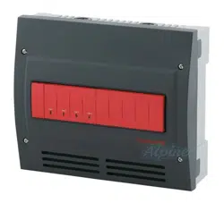
Terminal # 5-6 7-8 9-10 11-12
Terminal ID TH1 TH2 TH3 TH4
Function Zone call for heat
Equipment
Manufacturer
Model #
Date Code
Notes
Terminal ID Zone 1 Zone 2 Zone 3 Zone 4
System Zone #
Function Zone control
Equipment Pump Pump Pump Pump
Manufacturer
Model #
Date Code
Power draw
Amps
Notes
M27621A
Zone 1
Zone 2
Zone 3
Zone 4
C1 DIP switch
(See back for
settings)
Terminal # 5-6 7-8 9-10 11-12
Terminal ID TH1 TH2 TH3 TH4
Function Zone call for heat
Equipment
Manufacturer
Model #
Date Code
Notes
Terminal ID Zone 1 Zone 2 Zone 3 Zone 4
System Zone #
Function Zone control
Equipment Pump Pump Pump Pump
Manufacturer
Model #
Date Code
Power draw
Amps
Notes
M27621A
Zone 1
Zone 2
Zone 3
Zone 4
C2 DIP switch
(See back for
settings)
AQ25582B EXPANSION ZONING PANEL FOR 8 PUMPS
Automation and Control Solutions
Honeywell International Inc.
1985 Douglas Drive North
Golden Valley, MN 55422
customer.honeywell.com
® U.S. Registered Trademark
© 2013 Honeywell International Inc.
69-1980—05 L.L. Rev. 10-13
Printed in United States
C1 Zoning Module DIP Switch Settings
C2 Zoning Module DIP Switch Settings
* If used with AQ250 RelayPlus Control Panel, the AQ15000B Boiler Control
Module DIP switch #5 must be set to “GROUP” position and DIP switch #6 must
be set to “MAIN” position
If used with AQ251 Boiler Reset Control Panel, the EQUIPMENT SETUP >
AUXILIARY I/O > AUX PUMP menu option on the AQ251 must be set to
"GROUP"
DIP
Number
Description
1 Zone Address
(Slide the DIP switch to the right position to indicate which group of zones
this is; should be set to "1-4" for the first 4 space heating zones in the
system [usually included with an AQ250 or AQ251 control panel], then
"5-8" for the next group of 4 zones and so on. For each group of 4 zones,
there can be only one
DIP switch in the right hand position.)
2
3
4
5
• If set to SYNC, zone synchronization is enabled.
• If set to NOT, zone synchronization is disabled.
6
• If zone valves are normally closed (N.C.), set the NC/NO DIP switch to
the OFF position.
• If zone valves are normally open (N.O.), set the NC/NO DIP switch to
the ON position.
7
• If set to Group (ON position) the zone outputs are energized with the
AUX pump*.
• If set to - (OFF position), the AUX Pump contacts are not affected by
activity on these zones.
8
• If set to 2-Stg (ON position), then 2-stage operation is activated on
thermostat inputs. The zoning module operates as two 2-stage zones
or 3 zones (one 2-stage and two 1-stage).
• If set to 1-Stg (OFF position), then operates as four 1-stage zones.
M23715
Test
Diagnostic
Test
Diagnostic
Factory
Setting
Installer
Setting
Fill in the circle to
indicate position
of DIP switch.
M23720
A
AQ15540B
Test
Diagnostic
Test
M34972
ON
12345678
* If used with AQ250 RelayPlus Control Panel, the AQ15000B Boiler Control
Module DIP switch #5 must be set to “GROUP” position and DIP switch #6 must
be set to “MAIN” position
If used with AQ251 Boiler Reset Control Panel, the EQUIPMENT SETUP >
AUXILIARY I/O > AUX PUMP menu option on the AQ251 must be set to
"GROUP"
DIP
Number
Description
1 Zone Address
(Slide the DIP switch to the right position to indicate which group of zones
this is; should be set to "1-4" for the first 4 space heating zones in the
system [usually included with an AQ250 or AQ251 control panel], then
"5-8" for the next group of 4 zones and so on. For each group of 4 zones,
there can be only one
DIP switch in the right hand position.)
2
3
4
5
• If set to SYNC, zone synchronization is enabled.
• If set to NOT, zone synchronization is disabled.
6
• If zone valves are normally closed (N.C.), set the NC/NO DIP switch to
the OFF position.
• If zone valves are normally open (N.O.), set the NC/NO DIP switch to
the ON position.
7
• If set to Group (ON position) the zone outputs are energized with the
AUX pump*.
• If set to - (OFF position), the AUX Pump contacts are not affected by
activity on these zones.
8
• If set to 2-Stg (ON position), then 2-stage operation is activated on
thermostat inputs. The zoning module operates as two 2-stage zones
or 3 zones (one 2-stage and two 1-stage).
• If set to 1-Stg (OFF position), then operates as four 1-stage zones.
M23715
Test
Diagnostic
Test
Diagnostic
Installer
Setting
Fill in the circle to
indicate position
of DIP switch.
Factory
Setting
M23720A
AQ15540B
Test
Diagnostic
Test
M34972
ON
12345678