INSTALLATION JOB RECORD
AQ25542B Expansion Zoning Panel for 4 Pumps
System commissioning date: _________________________
Customer: _______________________________________
Building address: _________________________________
INSTRUCTIONS:
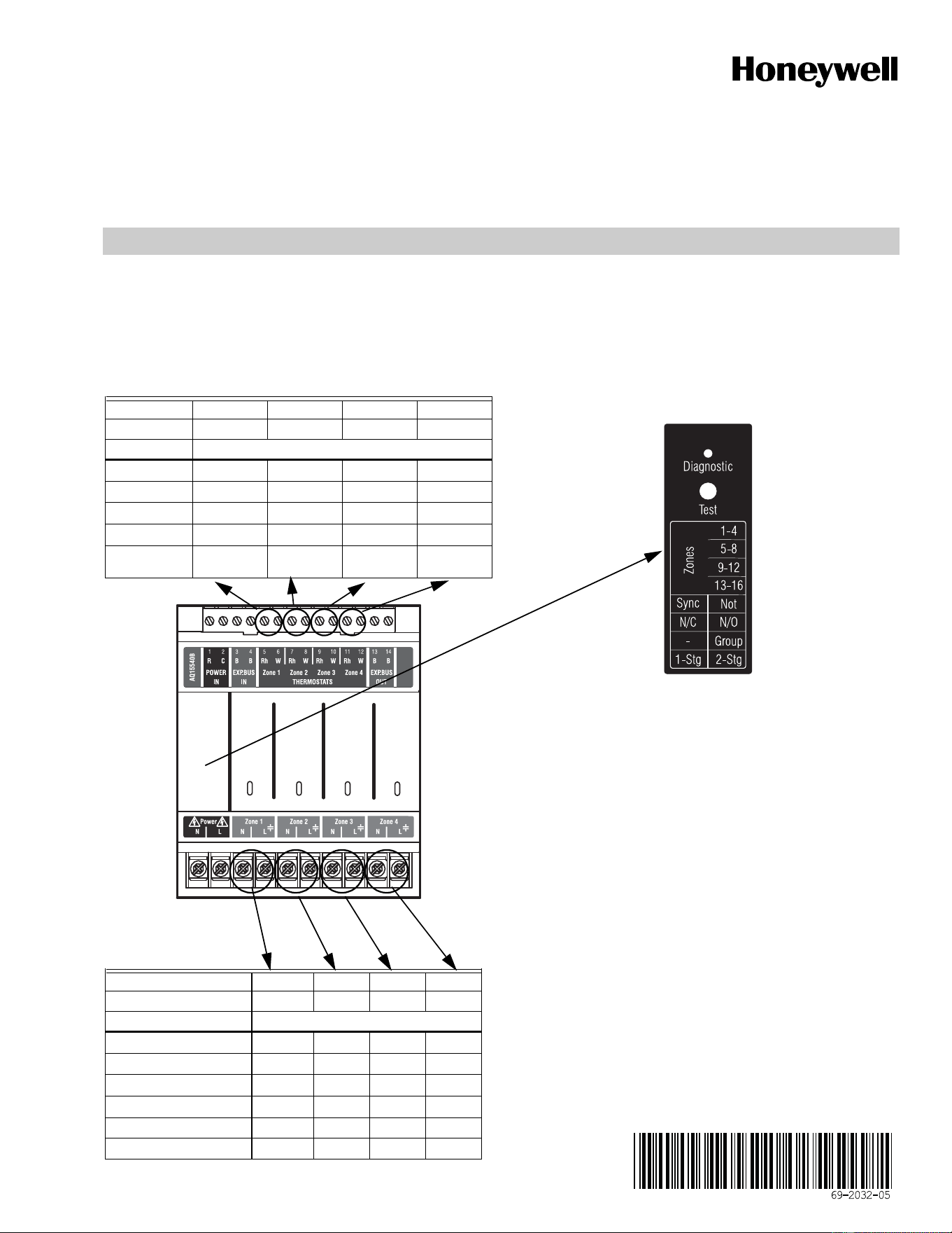
Fill in the details of the equipment connected to the zoning module:
A Low voltage thermostats
B Line voltage pumps
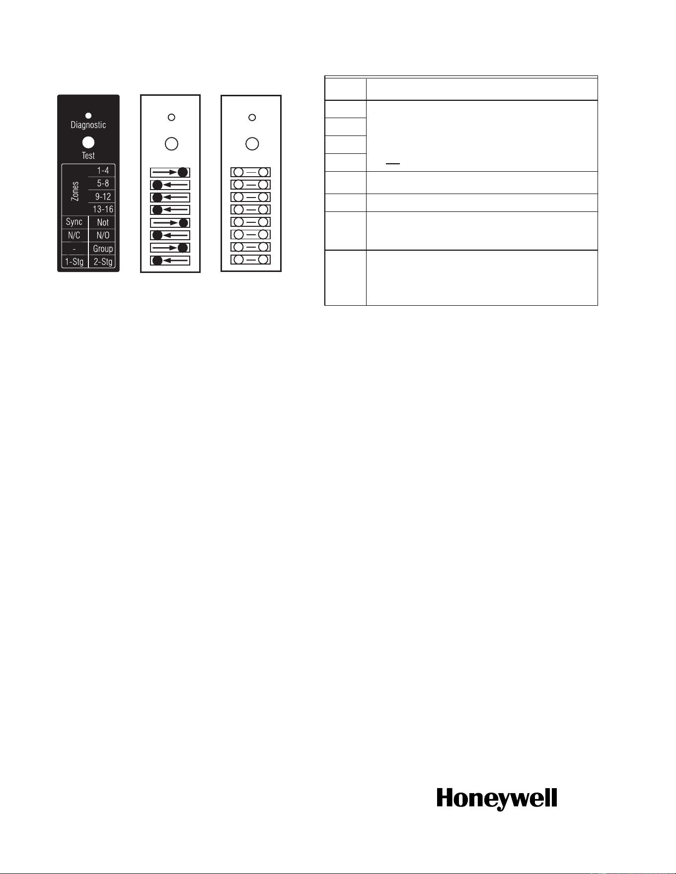
C Review and set DIP switch settings - once the DIP switches have been set, complete the “Installer settings” diagram by filling in the circles
to indicate the DIP switch position
File this with other installation records for equipment used on this installation.
A Zoning Thermostats
B Zoning Pumps
Terminal # 5-6 7-8 9-10 11-12
Terminal ID TH1 TH2 TH3 TH4
Function Zone call for heat
Equipment
Manufacturer
Model #
Date Code
Notes
Terminal ID Zone 1 Zone 2 Zone 3 Zone 4
System Zone #
Function Zone control
Equipment Pump Pump Pump Pump
Manufacturer
Model #
Date Code
Power draw Amps
Notes
M27621A
Zone 1
Zone 2
Zone 3
Zone 4
M23720
A
AQ15540B
Automation and Control Solutions
Honeywell International Inc.
1985 Douglas Drive North
Golden Valley, MN 55422
customer.honeywell.com
® U.S. Registered Trademark
© 2013 Honeywell International Inc.
69-2032—05 L.L. Rev. 10-13
Printed in United States
C Zoning Module DIP Switch Settings
* If used with AQ250 RelayPlus Control Panel, the AQ15000B Boiler
Control Module DIP switch #5 must be set to “GROUP” position
and DIP switch #6 must be set to “MAIN” position
If used with AQ251 Boiler Reset Control Panel, the EQUIPMENT
SETUP > AUXILIARY I/O > AUX PUMP menu option on the AQ251
must be set to "GROUP"
M23715
Test
Diagnostic
Test
Diagnostic
Factory
Setting
Installer
Setting
Fill in the circle to
indicate position
of DIP switch.
M23720A
AQ15540B
Test
Diagnostic
Test
M34972
ON
12345678
DIP
Number
Description
1
Zone Address
(Slide the DIP switch to the right position to indicate which
group of zones this is; should be set to "1-4" for the first 4
space heating zones in the system [usually included with an
AQ250 or AQ251 control panel], then "5-8" for the next group
of 4 zones and so on. For each group of 4 zones, there can be
only one DIP switch in the right hand position.)
2
3
4
5
• If set to SYNC, zone synchronization is enabled.
• If set to NOT, zone synchronization is disabled.
6
N/A when zoning with pumps
7
• If set to Group (ON position) the zone outputs are
energized with the AUX pump*
• If set to - (OFF position), the AUX Pump contacts are not
affected by activity on these zones.
8
• If set to 2-Stg (ON position), then 2-stage operation is
activated on thermostat inputs. The zoning module
operates as two 2-stage zones or 3 zones (one 2-stage
and two 1-stage).
• If set to 1-Stg (OFF position), then operates as four
1-stage zones.