QUICK INSTALLATION GUIDE
69-1982
AQ250 Series Hydronic Control Panels
10 QUICK INSTALLATION STEPS TO
SETTING UP AN AQ250 SERIES
CONTROL PANEL
1. Check you have all the necessary equipment for
a successful installation
2. Read all instructions carefully before
proceeding
3. Familiarize yourself with the AQ250 Control
Panel
4. Mount Control Panel on the wall, along with any
Expansion Zoning Panels
5. Mount thermostats in the zones
6. Wire all system components to the Control
Panel
7. Configure the Control Panel's DIP switches
8. Test and Check Out the Installation
9. Purge the air from all zone piping using the
AQ250 built-in Purge Routine feature
10. Document and keep a record of all system
settings
CONTENTS
1 Check You Have All the Necessary Equipment ............. 2
2 Read All Instructions Carefully Before Proceeding ....... 2
3 Familiarize Yourself With the Control Panel .................. 2
4 Mount Control Panel On The Wall,................................. 3
5 Mount Thermostats In The Zones ................................. 4
6 Wire All System Components To The Control Panel ..... 4
7 Configure The Control Panel's DIP Switches ................ 10
8 Test and Check Out the Installation ............................... 12
9 Purge Air using the built-in Purge Routine feature ........ 18
10 Document and Keep A Record Of All System Settings 14
Appendix ......................................................................... 15
Troubleshooting ............................................................... 15
NOTE
Throughout these instructions, the following terminology
conventions are used:
• The term “AQ250” is used when the information
applies to both the AQ2504B2 and AQ2504B4 Con-
trol Panels. Where there are specific instructions or
details relating to the “-4B2” or “-4B4” Control Pan-
els, the full model number (i.e. AQ2504B4) is used;
• The term “Control Panel” refers to an assembled
product, consisting of a transformer, Control Module
and Zoning Module, all contained within an AQ2000
panel enclosure;
• The term “AQ255” refers to all of the AQ2554P2X,
AQ2558P2X and AQ2554V2 Expansion Zoning Pan-
els and “AQ257” refers to the AQ2574V4 Expansion
Zoning Panel. Where there are specific instructions
or details relating to the “-4P2X”, “-8P2X”, “-4V2”, or
“-4V4” Expansion Zoning Panels, the full model num-
ber (i.e. AQ2574V4) is used;
• The term “Expansion Zoning Panel” refers to an
assembled product, consisting of a Zoning Module
and—if applicable—a transformer, contained within
an AQ2000 panel enclosure; Zoning Modules are
available in either 4-zone or 8-zone configurations.
Refer to Honeywell literature Form No. 69-1981 for
more information on these products.
• The term “AQ1500” refers to the AQ1500B0 Control
Module;
• The term “Control Module” refers to the component
within an AQ2000 Series Control Panel that performs
the “master control operations”. See Table 1 for spe-
cific models.
• The term “Zoning Module” refers to the component
within an AQ2000 Series Control Panel or Zoning
Expansion Panel.
• The term “AQ155” refers to the AQ1554P2 Zoning
Module and “AQ157” refers to the AQ1574V4 Zoning
Module.
Table 1.
Control Panel
Corresponding
Control Module
Corresponding
Zoning Module
AQ2504B2 AQ1500B0 AQ1554P2
AQ2504B4 AQ1500B0 AQ1574V4
AQ250 SERIES HYDRONIC CONTROL PANELS
69-1982 2
1 Check You Have All the Necessary
Equipment For a Successful
Installation
A) AQ2000 Series components
• AQ250 Control Panel
• AQ Expansion Zoning Panels (if more than four
space heating zones in the system)
• AQ1000 Thermostats (one for every space heating
zone being controlled)
B) Boiler supply and return temperature sensors (included
with AQ250 Control Panels)
C) Low voltage thermostat wire
D) Zoning equipment (zone valves or pumps)
2 Read All Instructions Carefully
Before Proceeding
The AQ250 Control Panels are part of a totally new family of
hydronic controls! And although they - and other AQ2000
system components - are VERY easy to install and operate,
they’re different than other hydronic controls that you have
previously installed. So take a moment to read through this
quick installation guide BEFORE beginning the installation.
Failure to follow them could damage the product or cause a
hazardous condition.
3 Familiarize Yourself With The AQ250
Control Panel
Layout
AQ250 Control Panels consist of three functional
components:
• the AQ10X38 transformer (power supply module), which
connects to 120 Vac power and supplies 24Vac power to
the Control Module and Zoning Modules; and
• the AQ1500B0 boiler / DHW Control Module, which
controls the boiler and domestic hot water (DHW) functions
as well as coordinating the overall operation of the
hydronic system
• a Zoning Module capable of controlling 4 space heating
zones
The Zoning Module is available in two versions:
• AQ1574V4 (part of the AQ2504B4 Control Panel) for
zoning with 24 Vac zone valves with end switches
• AQ1554P2 (part of the AQ2504B2 Control Panel) for
zoning with either line voltage circulators or 24 Vac zone
valves without end switches.
AQ250 Control Panels can control a maximum of 16 zones by
connecting up to 3 additional Expansion Zoning Panels to the
AQ250 Control Panel. Each Expansion Zoning Panel is
configured with its own bank of DIP switches, located in the
left most section of each Zoning Module. To expand the
capacity of an AQ250 Control Module beyond 16 zones, an
AQ254 Add-A Temperature Expansion Control Panel is
required. The hydronic system can be expanded by 16 zones
for each AQ254 connected to the AQ2000 network; a
maximum of three (3) AQ254 Panels may be connected to an
existing AQ2000 Control Panel for a total system capacity of
64 zones.
NOTE: If an AQ254 is used for controlling the temperature in
a mixed loop, it can reset the that mixed loop temper-
ature using LOAD reset, but not OUTDOOR reset,
as the AQ250 panel does not have input terminals
for an outdoor sensor.
In general, the top terminals of all AQ2000 Series Control
Panel components carry low voltage (24 Vac) power and the
bottom terminals carry line voltage (120V) power. The only
exception to this is the AQ1554P2 Zoning Module when used
with low voltage zone valves (without end switches). In this
case, the bottom terminals of the Transformer and Control
Module carry line voltage, but the bottom terminals of the
Zoning Module will carry low voltage power.
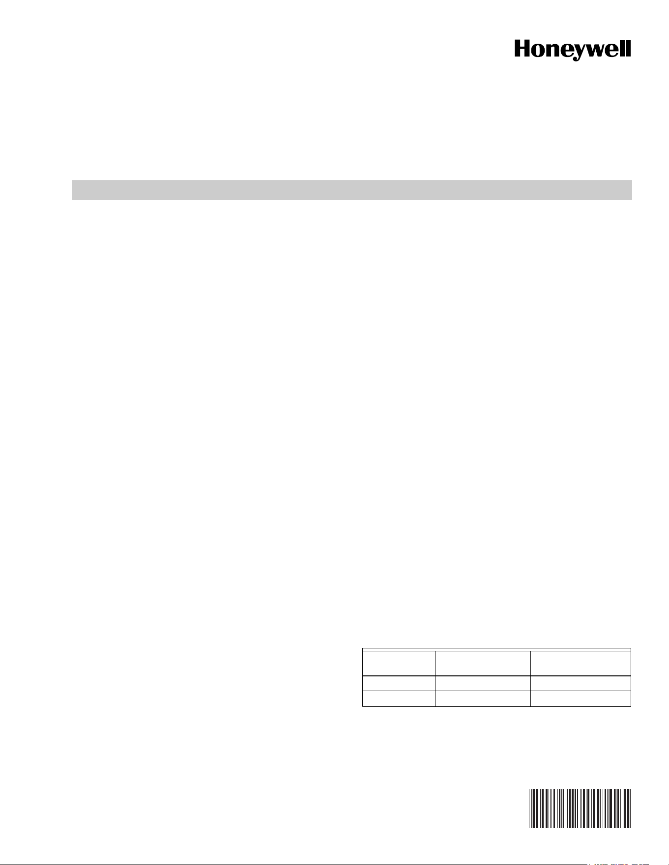
Fig. 1 AQ250 Control Panel Layouts (AQ2504B4 shown)
Zone 1
Zone 2
Zone 3
Zone 4
ZR
Boiler
DHW
Aux
M23734A
LOW VOLTAGE
(24 V)
LOW VOLTAGE
(24 V)
ZONING MODULE
CONTROL MODULE
TRANSFORMER
LINE VOLTAGE
(120 V)
AQ250 SERIES HYDRONIC CONTROL PANELS
3 69-1982
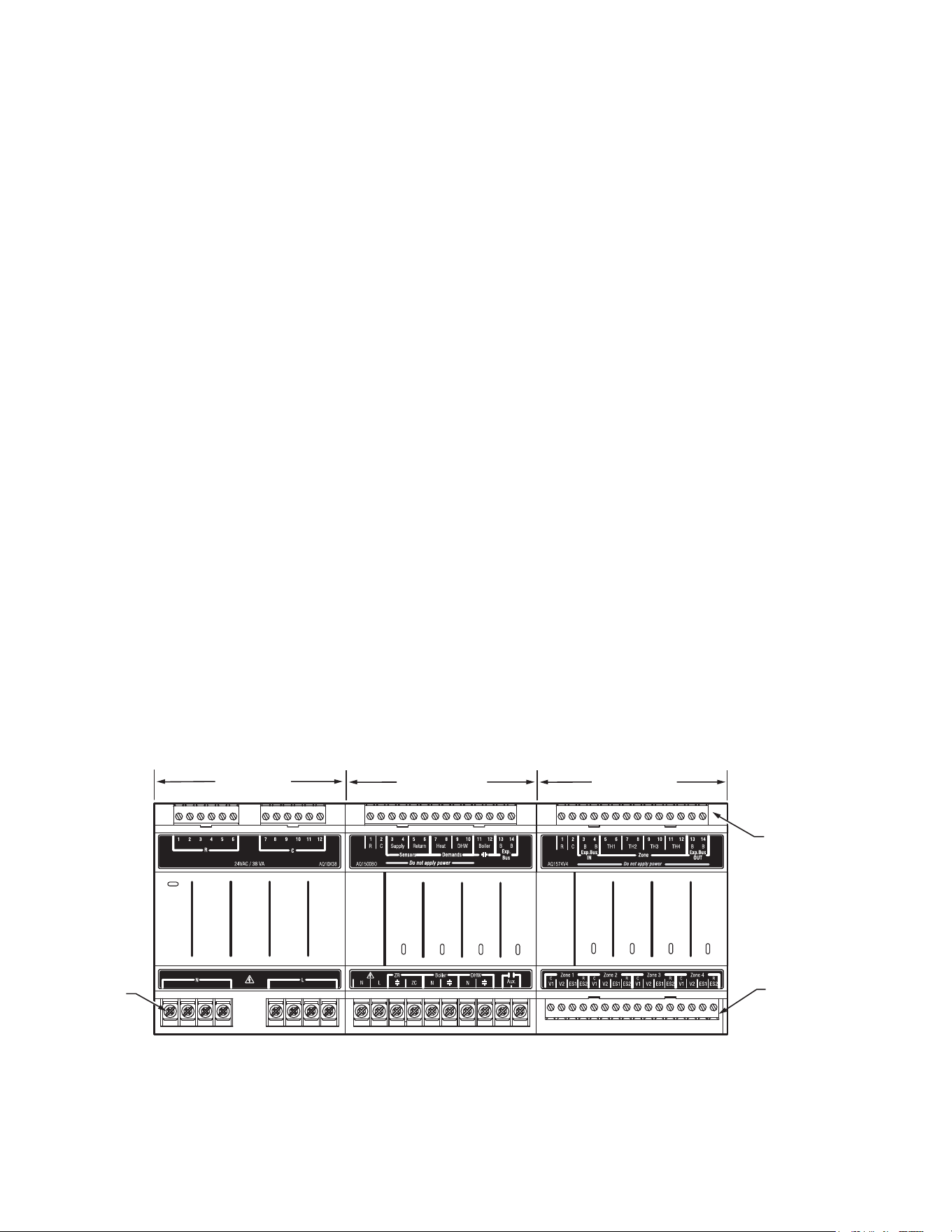
Fig. 2 Internal wiring for AQ2000 Series components line voltage relays
4 Mount Control Panel On The Wall,
Along With Any Expansion Zoning
Panels
When Installing this Product
• Read these instructions carefully. Failure to follow them
could damage the product or cause a hazardous condition.
• Check the ratings given in the instructions and on the
product to make sure the product is suitable for the
application.
• Installers must be trained, experienced, licensed service
technicians.
• Follow local codes for installation and application.
• After installation is complete, check out product operation
as printed in these instructions.
1. Use template supplied with the AQ250 Control Panel to
mark the four mounting holes for the panel.
2. Install two top screws, mount panel and then install two
lower screws.
If there are Expansion Zoning Panels to install, they should be
mounted on the wall now. If not, skip this section and proceed
to Step 5 “Mount Thermostats In The Zones”.
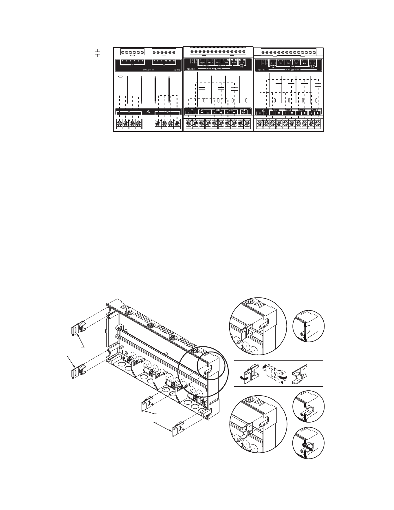
3. Remove wire channel plugs from the AQ250 Control
Panel and any Expansion Panels (see Figure 3).
4. Mount Expansion Zoning Panel on the right hand end of
the AQ250 Control Panel. Install two top screws of the
Expansion Zoning Panel, ensuring it is level with the
adjoining Control Panel, and install two lower screws.
5. Reverse wire channel plugs and re-insert them into their
slot to from a wiring channel between the Control Panel
and the Expansion Zoning Panel (see Figure 3) and to
connect the two panels together.
6. If there are additional Expansion Zoning Panels, repeat
Steps 3-5 above.
Fig. 3 Orientation of Wire Channel Plugs for Creating pass-through wire channel and
for Joining Control Panel to Expansion Zoning Panels
M13896
Zone 1
Zone 2
Zone 3
Zone 4
CONTACTS
SYMBOL
ZR
Boiler
DHW
Aux
M23733A
WIRE
CHANNEL
PLUGS
WIRE
CHANNEL
PLUGS
AQ250 SERIES HYDRONIC CONTROL PANELS
69-1982 4
5 Mount Thermostats In The Zones
Referring to the installation instructions (form # 69-2005)
included with the AQ1000 thermostats, install the thermostats
on the walls in the zones that are to be controlled by the
AQ250 Control Panels. If not done already, run low voltage
thermostat wire (24 gauge or heavier) from the thermostats
back to the AQ250 Control Panel for installation in Step 6
“Wire All System Components to the Control Panel.”
6 Wire All System Components To The
Control Panel
NOTES: If not otherwise specified, low voltage wiring should
be run with 18 gauge thermostat wire and line volt-
age wiring should be run with 14 gauge wire.
AQUATROL line voltage screw terminals are
approved for use with 22 to 12 gauge copper.
Several wiring diagrams are included in this docu-
ment. For additional information, refer to http://cus-
tomer.honeywell.com or your local distributor.
AQ250 Control Panels are pre-wired at the factory (as
described below), making for faster installation:
• The low voltage output terminals located at the top of the
transformer are wired to the R and C input terminals of the
Control Module, and the R and C inputs on the top of the
Zoning Module.
• The B-B “Exp. Bus” terminals of the Control Module are
wired to the B-B “Exp. Bus IN” terminals of the Zoning
Module.
Wiring Procedure
Beginning with the top left of the Control Panel and moving
clockwise around the panel (refer to Figure 4), wire
components to the AQ250 Control Panel and Expansion
Zoning Panels (if installed) in the following six steps:
Step 1 Factory pre-wiring of the Control Panels is shown as
dotted lines in Figure 4. In addition to the pre-wiring,
run low voltage jumper wires from available R and C
terminals to the R and C terminals of any Expansion
Zoning Panels
Step 2 Temperature Sensors, System Demands and
Communication bus wiring.
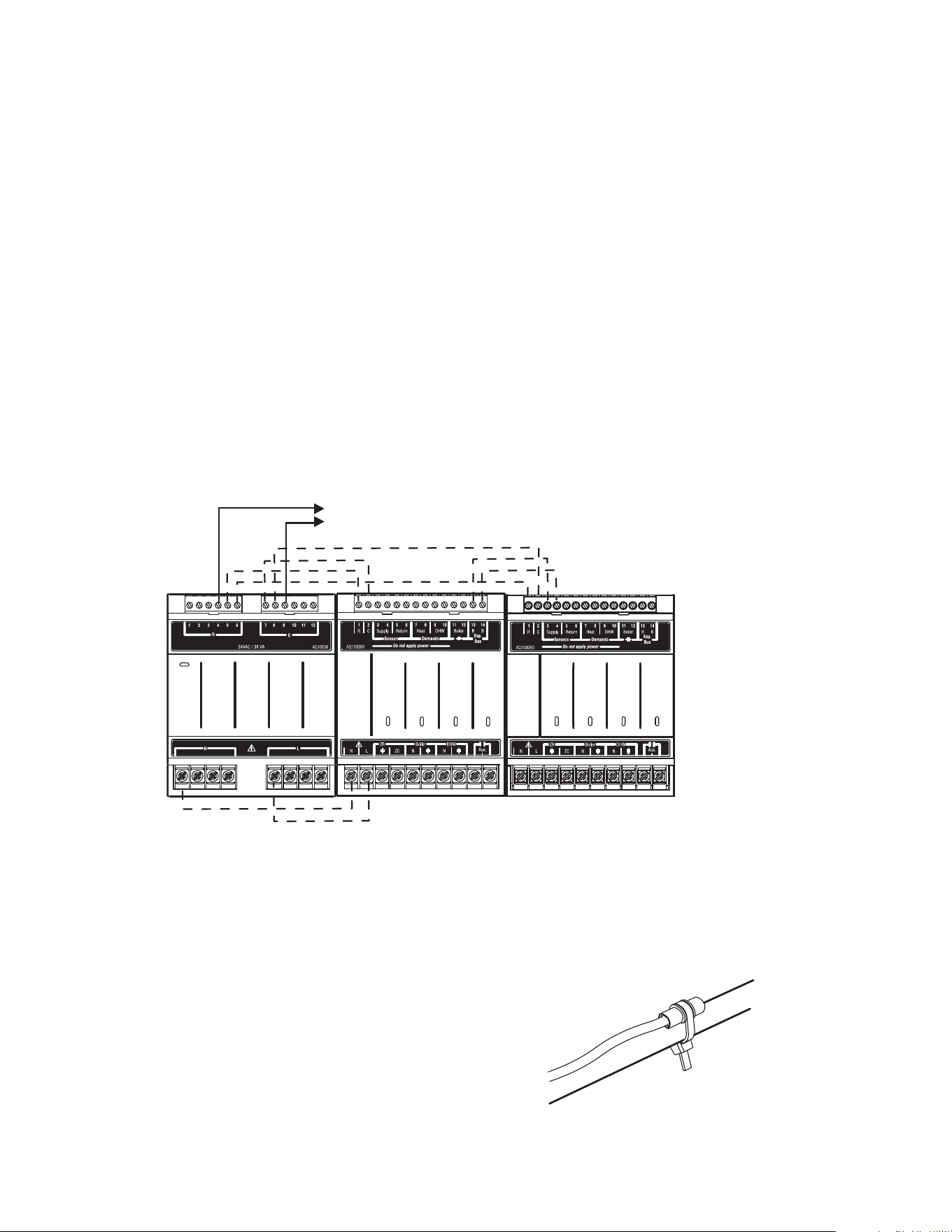
Fig. 4 Wiring Sequence
A) Temperature Sensors
WIRING
Connect the lead wires of each sensor to the corresponding
terminals on top of the AQ1500B0 Control Module. See
Figure 6.
1. Boiler Supply and Return Sensors.
The Boiler supply water sensor should be installed on
the supply piping close to the exit port of the boiler,
using one of the AQ12C11 strap-on sensors supplied
with the AQ250. See Figure 5.
The Boiler return sensor should be installed on the
return piping as close to the entrance port to the boiler
as practical using the other AQ12C11 strap-on sensor
supplied with the AQ250. The correct location is one
that will measure the temperature of all combined
sources of water returning back to the boiler.
Insulate strap-on sensors with pipe wrap to ensure
accurate boiler temperature sensing.
The supply and return water sensors come with 10 ft.
(3m) of wire to minimize the need for splicing.
Fig. 5 Strap-on temperature sensor installation
M13897
STEP 1 STEP 2 STEP 3
STEP 4
STEP 5STEP 6
TO EXPANSION ZONING MODULES
(IF INSTALLED)
ZR Boiler
DHW
Aux.
ZR
Boiler
DHW
Aux
M13763
AQ250 SERIES HYDRONIC CONTROL PANELS
5 69-1982
IMPORTANT
Do not run sensor wires parallel, or close, to tele-
phone, Ethernet, or power cables. Cross all power,
Ethernet, and telephone wiring at right angles. If sen-
sor wires are located in an area with strong sources
of electromagnetic interference (e.g. if sensor wires
are run in the same electrical chase as line voltage
wiring) use twisted pair, shielded cable, or run wires
in a grounded metal conduit. If using shielded cable
or conduit, connect the shield wire to earth ground
ONLY at the AQ250 panel. DO NOT ground the
shield or conduit at any other location or electromag-
netic shielding will be ineffective. If shielded cable is
used, Honeywell recommends the use of shielded
cable with a continuous ground plane, such as foil,
with an integral “drain wire” for bonding to earth
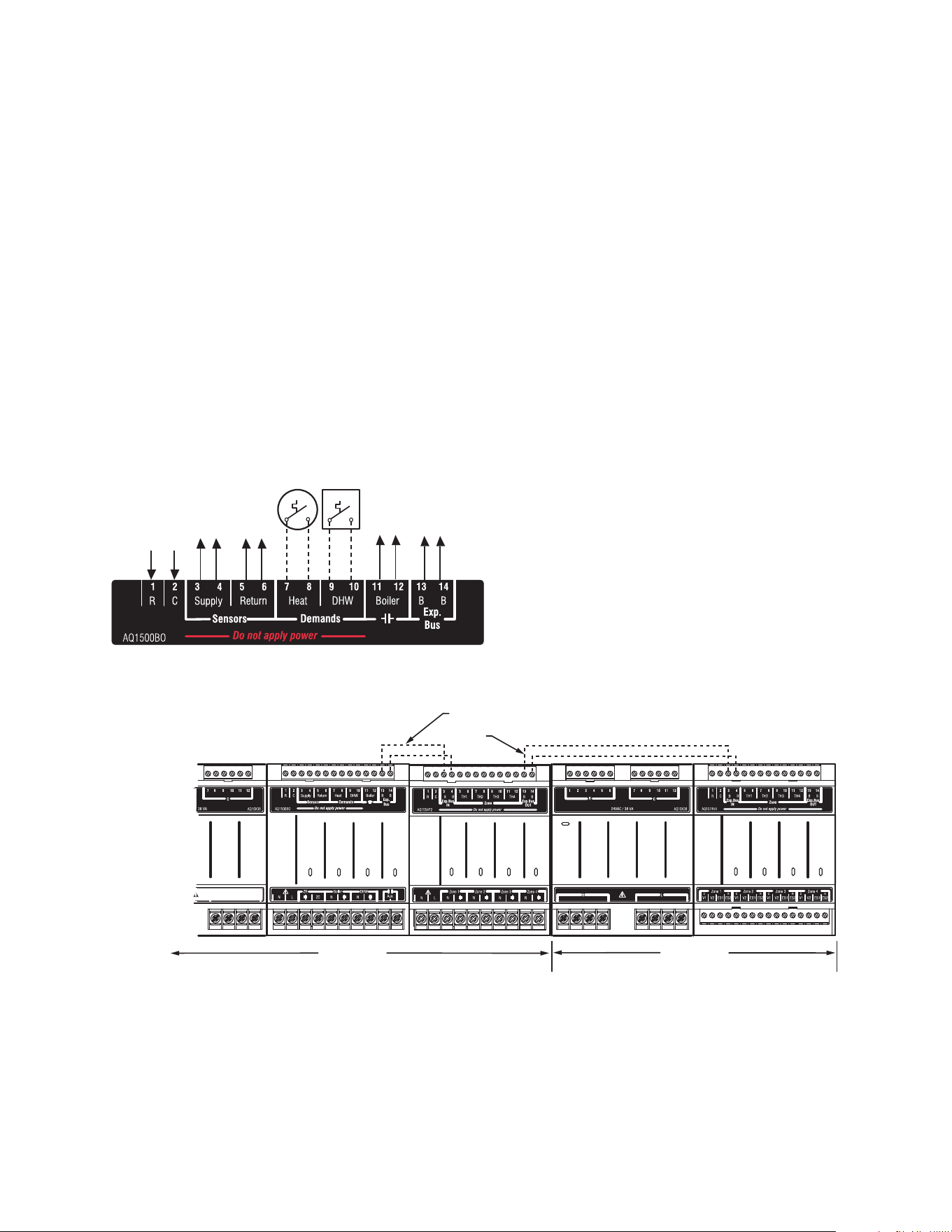
Fig. 6 Wiring for the AQ250 Control Modules
B) System Demands
1. Wire the HEAT Demand terminals (7-8) to a system set
point demand, such as a pool or spa (optional).
2. Wire the DHW terminals (#9-10) [optional] to the AQU-
ASTAT or thermostat on the Domestic Hot Water tank
C) Low Voltage Outputs
Wire the BOILER dry contact output (terminals 11-12) to the
T-T terminals on the boiler AQUASTAT. It is not necessary to
use the “T-T” terminals if connecting to a Triple Aquastat,
since the signal to the Aquastat is received from the “ZR” /
“ZC” terminals. See Figures 14a and 14b for line voltage
connection to boiler Aquastats.
D) Communication Bus Wiring
All AQ2000 components communicate with each other on the
AQUATROL network using “communication bus” wiring. This
wiring MUST connect all AQ2000 components, otherwise
features that depend on this networked communication (e.g.
zone synchronization) will not function.
This “communication bus” wiring is polarity insensitive – the
installer does not need to worry about a +ve or –ve orientation
of the wires – if there are two wires connected to the B-B “Exp.
Bus IN” and B-B “Exp. Bus Out”, there will be communication!
See example in Figure 7 for how this wiring is to be installed.
The communication bus connections are pre-wired at the
factory for both the “-4B2” and “-4B4” models.
Fig. 7 Wiring for Communication Bus
Step 3 AQ1000 THERMOSTATS
• Using low voltage thermostat wire, connect one AQ1000
communicating thermostat from each zone to the
corresponding “TH” inputs on top of the Zoning Module
(Figure 8).
• If there are additional zones (on Expansion Zoning Panels)
connected to this Zoning Module:
— Run low voltage thermostat wiring from the B-B
“Exp.Bus OUT” terminals (13-14) of the Zoning
Module to the B-B “Exp.Bus. IN” terminals (3-4) on the
Expansion Zoning Panel
Run low voltage thermostat wiring from the R and C terminals
on the Control Panel’s transformer to the R and C terminals
on the Expansion Zoning Panel. Alternatively, you can run low
TO BOILER SUPPLY SENSOR
TO BOILER RETURN SENSOR
TO SETPOINT LOAD
(OPTIONAL)
TO DHW AQUASTAT
IN FROM “R” TERMINAL
ON TRANSFORMER MODULE
(FACTORY-WIRED)
IN FROM “C” TERMINAL
ON TRANSFORMER MODULE
(FACTORY-WIRED)
TO “T-T” TERMINALS ON
BOILER AQUASTAT
TO B-B “EXP.BUS IN”
TERMINALS ON CONNECTED
ZONING MODULE
M13769
A
Zone 1
Zone 2
Zone 3
Zone 4
ZR
Boiler
DHW
Aux
Zone 1
Zone 2
Zone 3
Zone 4
DATA BUS
COMMUNICATION
WIRING
M13898
AQ2574V4
AQ2504B2
AQ250 SERIES HYDRONIC CONTROL PANELS
69-1982 6
voltage thermostat wiring from the R and C terminals on the
Zoning Module to the R and C terminals on the Expansion
Zoning Panel.
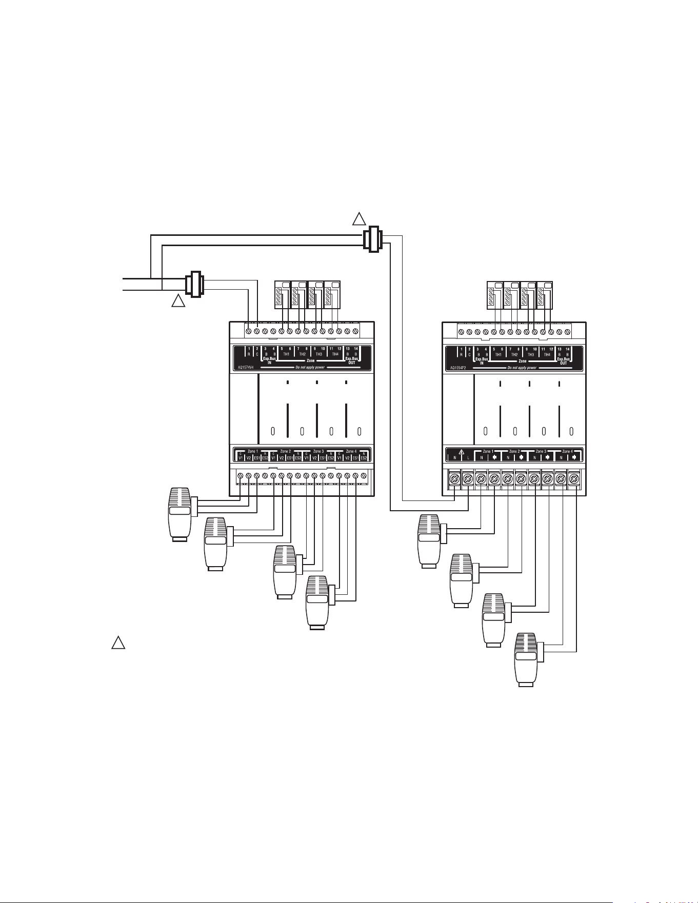
Fig. 8 Connecting AQ1000 Thermostats
Step 4 Zoning Equipment - Line Voltage Pumps Or Low
Voltage Zone Valves.
Since the Zoning Module of the AQ2504B2 Control
Panel can be used with either low voltage zone valves
(without end switches) or line voltage pumps or valves,
FIELD installed wiring of the correct voltage needs to
be connected to the zoning equipment terminals on
the bottom left portion of the Zoning Module.
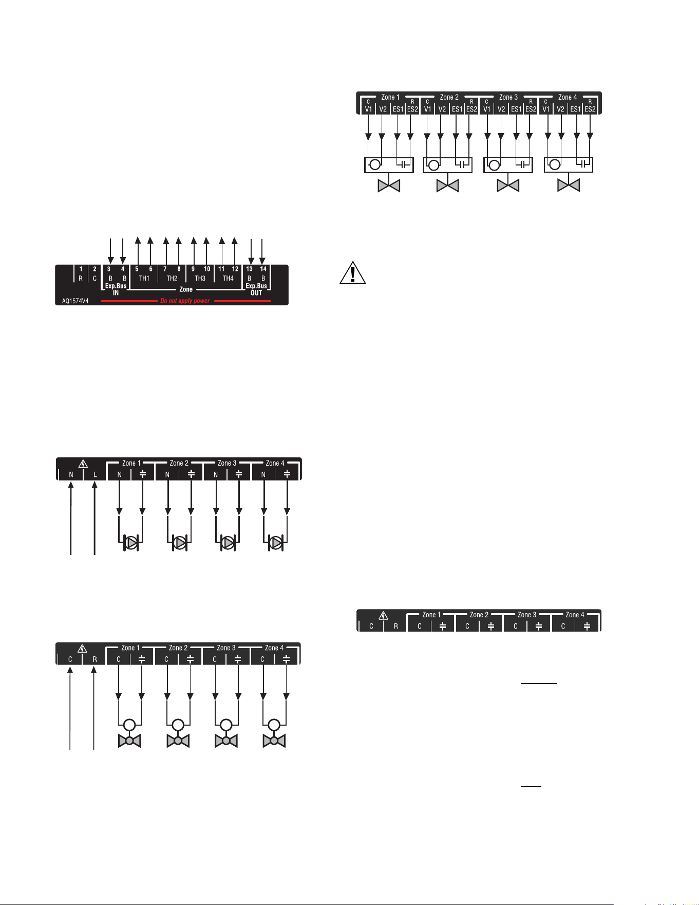
Fig. 9a Wiring an AQ1554P2 Zoning Module for
use with line voltage circulators.
Fig. 9b. Wiring an AQ1554P2 Zoning Module for use
with low voltage Zone Valves WITHOUT end switches.
Fig. 9c Wiring an AQ1574V4 Zoning Module for use
with low voltage Zone Valves WITH end switches.
CAUTION
The ES1 and ES2 terminals of the AQ1574V4
Zoning Module are powered terminals and must
ONLY be connected to a set of dry contacts. If
power is applied to these contacts (for example,
by running line voltage through the zone valves’
end switches to bring on a circulator feeding
those valves), the internal circuitry of the Zoning
Module will be damaged, in which case the
warranty for this product will be voided.
a. For line voltage circulators (Figure 9a), remove
the plastic wiring barrier (factory-installed) that's
located in the bottom wiring channel between the
AQ1500 Control Module and the Zoning Module.
Run jumper wires from the N and L terminals on the
bottom of the Control Panel’s transformer through
the wiring channel across the bottom of the Control
Panel to the corresponding N and L terminals of the
Zoning Module.
NOTE: If low voltage zone valves are used with the
AQ2504B2 Control Panel, the “low voltage out-
put” sticker supplied (shown in Figure 10)
MUST be applied over the “line voltage output”
sticker that is already attached to the Zoning
Module.
Fig. 10 Low Voltage Output Sticker
b. For low voltage zone valves without
end
switches (Figure 9b), run jumper wires from the R
and C terminals on the top left of the Control Panel’s
transformer through the wiring channel across the
top of the Control Panel, down through the wiring
channel on the right side of the panel and over to
the R and C terminals on the bottom of the Zoning
Module.
c. For low voltage zone valves with
end switches
(Figure 9c), 24 Vac power is pre-wired between the
transformer secondary at the top left of the AQ250’s
transformer and the AQ1574V4 Zoning Module, so
no field wiring is required.
FROM B-B “EXP. BUS”
TERMINALS ON
CONTROL MODULE
TO B-B “EXP. BUS IN” TERMINALS
ON CONNECTED ZONING MODULE
(IF AN EXPANSION ZONING PANEL
IS CONNECTED)
TO AQ1000
THERMOSTAT ON ZONE 1
TO AQ1000
THERMOSTAT ON ZONE 2
TO AQ1000
THERMOSTAT ON ZONE 3
TO AQ1000
THERMOSTAT ON ZONE 4
M13776B
FROM LINE VOLTAGE
120V TERMINALS
(N AND L) ON BOTTOM
OF TRANSFORMER
M13771
FROM LOW VOLTAGE
24 VAC TERMINALS
(C AND R) ON TOP
OF TRANSFORMER
MMMM
M13778
M
M13779
M
M
M
M23732
AQ250 SERIES HYDRONIC CONTROL PANELS
7 69-1982
NOTE: Wiring Zone Valves With End Switches -
Transformers VA.
If low voltage zone valves with end switches are
used for zone control, make sure the selected zone
valves do not draw more power (“VA”) than the 38 VA
capacity of the AQ10X38 transformer supplied with
the AQ250 Control Panels. This integral transformer
has enough power to operate 4 motorized zone
valves (such as Honeywell V8043E valves or 4
valves using low-amperage draw “heat motor” actua-
tors such as Honeywell MV100 actuators), plus
power the electronics of the AQ250's Control Module
and up to 16, AQ1000 thermostats. If zone valves
with high-amperage draw “heat motor” actuators are
used, such as Taco 500 series zone valves, an addi-
tional 24 Vac transformer of sufficient VA capacity will
need to be wired to the Zoning Module to power the
valves. See Figure 11 for recommended wiring of
additional low voltage VA capacity to AQ2000 Series
Zoning Modules.
Fig. 11 Wiring of additional low voltage VA capacity
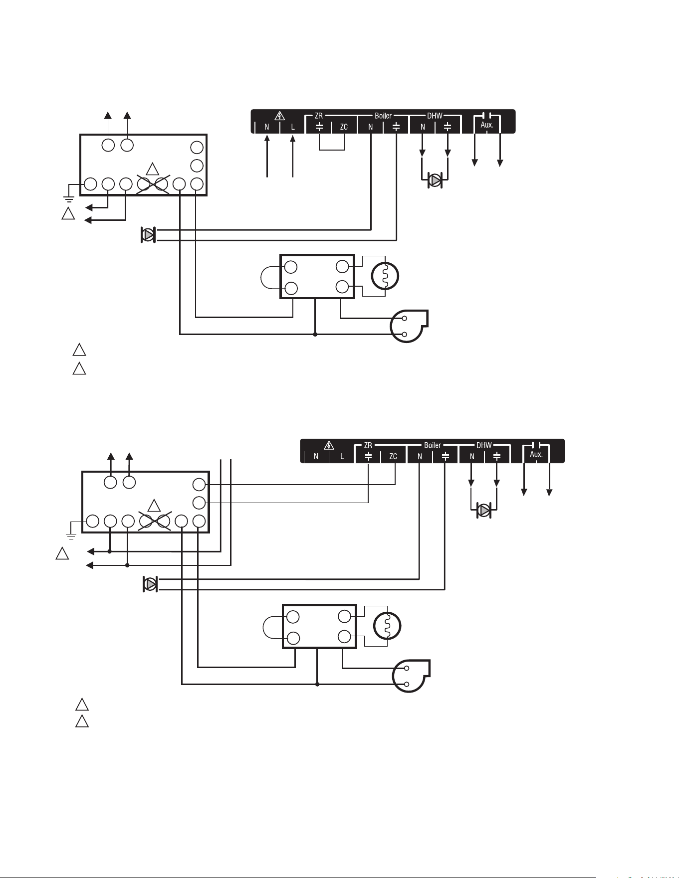
Step 5 Line Voltage System Outputs (Boiler Pump, DHW
Device, Aux Output)
See Figures 12a and 12b for wiring diagrams for the line
voltage outputs. Follow general instructions below for
wiring of these pumps to the AQ250 Control Module.
NOTE: It is not necessary to connect the boiler equipment’s
“T-T” terminals to the low voltage BOILER dry con-
tacts (Terminals 11-12) of the AQ250 when using a
Triple Aquastat on the boiler.
AQ1000
THERMOSTATS
ZONE 1 ZONE 2 ZONE 3
ZONE 4
M13866A
AQ1000
THERMOSTATS
ZONE 1 ZONE 2 ZONE 3
ZONE 4
Zone 1
Zone 2
Zone 3
Zone 4
USING AN AQ1574V4
VALVE ZONING MODULE
POWER SUPPLY. PROVIDE DISCONNECT MEANS AND OVERLOAD PROTECTION AS REQUIRED.
1
Zone 1
Zone 2
Zone 3
Zone 4
1
2
3
1
2
3
1
2
3
1
2
3
1
2
3
1
2
3
1
2
3
1
2
3
24 VAC
100 VA
TRANSFORMER
115 VAC
115 VAC
24 VAC
100 VA
TRANSFORMER
1
1
USING AN AQ1554P2
PUMP ZONING MODULE
AQ250 SERIES HYDRONIC CONTROL PANELS
69-1982 8
Fig. 12a Line Voltage Connections for AQ250.
Fig. 12b Line Voltage Connections for AQ250.
TO BOILER
TERMINALS 11-12
ON TOP OF AQ1500B0
CONTROL MODULE
ZC
ZR
B1 B2 C1 C2 L1 L2
T T
G
L8124, L7224
R8184
BURNER AND
IGNITION
C554
F
F
T
T
BLACK
WHITE
ORANGE
POWER SUPPLY. PROVIDE DISCONNECT MEANS AND OVERLOAD PROTECTION AS REQUIRED.
L1
(HOT)
L2
1
2
1
DO NOT WIRE THE BOILER LOOP CIRCULATOR TO THE AQUASTAT'S C1/C2 TERMINALS; IT MUST BE CONNECTED TO THE BOILER PUMP TERMINALS
ON THE BOTTOM OF THE AQ1500B0 CONTROL MODULE WHEN MAINTAINING A MINIMUM BOILER TEMPERATURE (WITH A TRIPLE FUNCTION AQUASTAT).
2
TO AUXILIARY DEVICE
(INSTALLER-DEFINED)
FROM LINE VOLTAGE
120V TERMINALS
(N AND L) ON BOTTOM
OF TRANSFORMER
JUMPERED
AT FACTORY
BOILER
PUMP
M13899
ZC
ZR
B1 B2 C1 C2 L1 L2
T T
G
L8124, L7224
R8184
BURNER AND
IGNITION
C554
F
F
T
T
BLACK
WHITE
ORANGE
POWER SUPPLY. PROVIDE DISCONNECT MEANS AND OVERLOAD PROTECTION AS REQUIRED.
L1
(HOT)
L2
1
1
FOR INSTALLATIONS USING A TRIPLE FUNCTION AQUASTAT, NOTE THAT THE FACTORY-INSTALLED JUMPER BETWEEN THE ZR AND ZC TERMINALS
MUST BE REMOVED. THE ZR AND ZC TERMINALS ON THE AQ1500B0 CONTROL MODULE MUST BE WIRED TO THE ZR AND ZC TERMINALS,
RESPECTIVELY, OF THE TRIPLE AQUASTAT.
2
TO AUXILIARY DEVICE
(INSTALLER-DEFINED)
BOILER
PUMP
M13900
N
L
TO LINE VOLTAGE 120V
TERMINALS (N AND L) ON
BOTTOM OF TRANSFORMER
TO BOILER TERMINALS
11 AND 12 ON TOP OF
AQ1500B0 CONTROL MODULE
2
AQ250 SERIES HYDRONIC CONTROL PANELS
9 69-1982
Boiler Pump
Connect the N and L wires of the boiler loop pump to
the N and switched “hot” terminals of the line voltage
“Boiler” output shown in Figure 13. The ground wire of
the pump can be connected to any of the 6 ground
screw terminals located on the back surface of the
Control Panel enclosure.
DHW Aquastat
Wire the DHW Aquastat to the N and switched “hot” ter-
minals of the DHW output as shown in Figure 13. If
using a low voltage zone valve, wire the primary of a
spud-mounted transformer (115V - > 24V) to the DHW
line voltage contacts and connect the low voltage zone
valve to the secondary terminals of this transformer. A
spud-mounted transformer may be located in one of the
conduit knockouts on the bottom of the AQ250 Control
Panel.
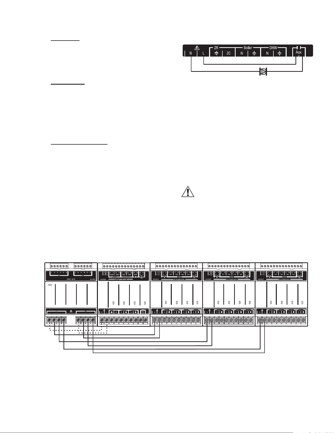
Line Voltage Aux Output
NOTE: Use of this output is optional
To connect a line voltage auxiliary device to these con-
tacts, such as a boiler bypass pump, power the pump
from the N and L terminals on the bottom of the Control
Module, running the L “hot” lead through the AUX.Pump
contacts. See Figure 13 for details.
NOTE: The AUX.Pump dry contacts are line voltage-
rated but unpowered. Wire the Installer-
defined AUXiliary output to the line voltage
AUX terminals, as shown in Figure 13. The
exact wiring schematic will depend on what is
connected to these dry contacts.
Fig. 13 Wiring of the AUX.Pump line voltage-rated dry
contacts (example shown is a by-pass pump).
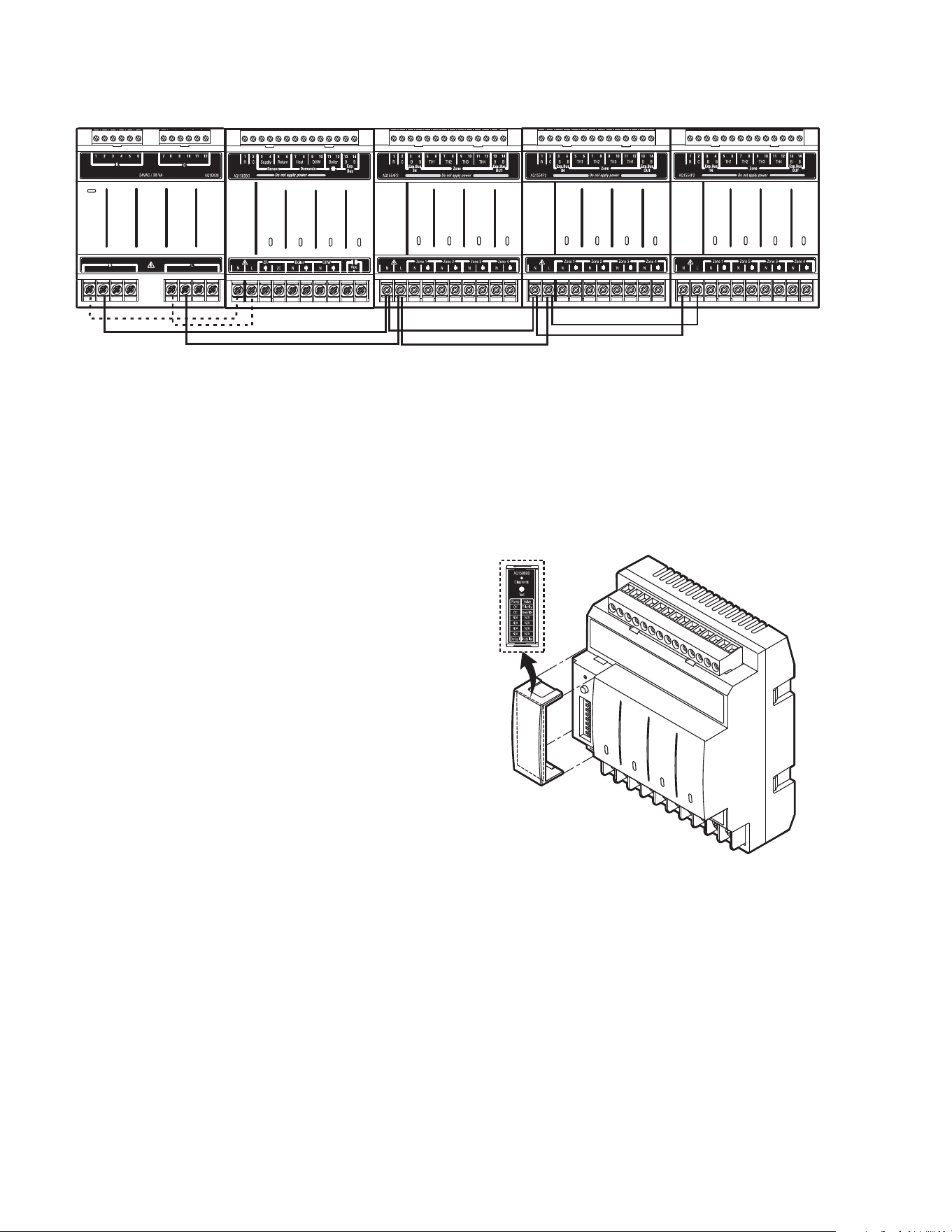
Step 6 Connection To Line Voltage Power
Finally, connect the N and L line voltage inputs of the
AQ250 Control Panel (at the bottom of the
transformer) to the electrical distribution panel and
power up the Control.
A service switch should be
installed on the L “hot” lead to the distribution panel.
If multiple Zoning Modules are connected to the AQ250
Control Panel, the line voltage wiring can either be run
directly from the N and L terminals on the transformer to
each of the Zoning Modules (Figure 14a) or run in
“daisy chain’ fashion from the N and L terminals of one
AQ2000 Module to the N and L terminals of another
Module (Figure 14b).
CAUTION
Electrical Shock or Equipment Damage Hazard.
Can shock individuals or short equipment
circuitry.
When line voltage is applied to the AQ250 Control
Panel and the front cover of the Panel is removed,
there is a risk of electrocution. Be careful to avoid
contact with the line voltage (N and L) terminals, either
with your fingers or with metal tools (such as a
screwdriver) when power is applied to the Control
Panel.
Fig. 14a Connections for Multiple Zoning Panels - Parallel Wiring
M13902
BY-PASS PUMP
ZR
Boiler
DHW
Aux
Zone 1
Zone 2
Zone 3
Zone 4
Zone 1
Zone 2
Zone 3
Zone 4
Zone 1
Zone 2
Zone 3
Zone 4
M13781
AQ250 SERIES HYDRONIC CONTROL PANELS
69-1982 10
Fig. 14b Alternate Connections for Multiple Zoning Panels - Daisy Chain Wiring
7 Configure The Control Panel's DIP
Switches
Setting up an AQ250 Control Panel is quick, simple and
straightforward. Only two steps are required – checking the
DIP switch settings for the Control Module and checking the
DIP switch settings for the Zoning Module(s).
Operation of the AQ250’s Control Module is set by the
positions of its DIP switches, which are located behind the
blank cover in the left most section of the Control Module
(beside the section labeled “ZR”). See Figure 15 for location
of these DIP switches.
AQ250 Control Panels come from the factory with pre-defined
settings for all DIP switches. These factory “default” settings
were chosen because they are commonly-used by hydronics
contractors across North America. That means that most of
the settings only need to be “checked” by the installing
contractor to make sure they’re suitable for the installation.
Although for many installations, these factory default values
for the Control Module and the Zoning Module(s) will be
suitable, Honeywell recommends that they be reviewed – and
changed, as necessary – to get optimal performance of the
hydronic system controlled by the AQ2000 Series products.
DIP Switch Configuration
Control Module
1. A chart of the setting options for each DIP switch is
attached to the inside of the DIP switch cover. More
detailed explanations for these settings, including the
pre-set factory defaults for each DIP switch, is shown in
Table 2.
Zoning Modules
2. The AQ1554P2 (pump Zoning Module) and AQ1574V4
(valves with end switches Zoning Module) both have
DIP switches in 8-switch “banks” and are concealed
behind snap-on covers as shown in Figure 15. A chart
of the different settings for each DIP switch is attached
to the inside of the DIP switch covers. More detailed
explanations for these DIP switch settings, including the
pre-set factory defaults for each, is shown in Table 3.
3. The only difference in setting up the AQ1554P2 and
AQ1574V4 Zoning Modules is that DIP switch #5 for the
AQ1554P2 needs to be set to “PUMP” or “VALVE”,
according to whether this Zoning Module will be used
for zoning with either pumps or zone valves without end
switches. DIP Switch #5 is not functional on the
AQ1574V4 Zoning Module, as this Zoning Module can
only be used for valve zoning.
Fig. 15 Location of concealed DIP switches for AQ1500B0
Control Module and AQ155 / AQ157 Zoning Modules
Check the DIP switch settings and, if necessary, change the
position of the DIP switches to suit the desired operation of
the hydronic installation.
4. DIP switches #1-4 define the “identity”, or “address”, of
each zone on the AQUATROL network. This is how the
Control Module knows that – for example – the zone
labeled “Zone 1” on the first Zoning Module is different
than the zone labeled “Zone 1” on a second Zoning
Module.
5. If there is more than one Zoning Module connected to
the AQ1500 Control Module, DIP switches #1-4 MUST
be set to uniquely identify each zone in the installation.
ZR
Boiler
DHW
Aux
Zone 1
Zone 2
Zone 3
Zone 4
Zone 1
Zone 2
Zone 3
Zone 4
Zone 1
Zone 2
Zone 3
Zone 4
M13781
M23731
AQ250 SERIES HYDRONIC CONTROL PANELS
11 69-1982
a. For the first Zoning Module - which is included as
part of the AQ250 Control Panel, make sure that
DIP switch #1 is set to the right hand position (the
factory default setting) and DIP switches #2-4 are
set to the left.
b. For the second Zoning Module connected to the
AQ1500 Control Module, make sure that DIP switch
#2 is set to the right hand position and DIP switches
#1, 3, and 4 are set to the left.
c. For the third Zoning Module connected to the
AQ1500 Control Module, make sure that DIP switch
#3 is set to the right hand position and DIP switches
#1, 2, and 4 are set to the left.
NOTE:Since AQ250 Control Panels have TWO
banks of DIP switches - one for the Control
Module and one for the Zoning Module - be
careful not to get the removable covers for
these DIP switches mixed up. Mixing up the
covers could result in setting the correspond-
ing Modules' DIP switches incorrectly if fol-
lowing the DIP switch settings charts
attached to the backs of the covers. To help
avoid this, the part number for each Module
(e.g. AQ1500B0 for the Control Module) is
printed on the top of the DIP switch settings
charts. The part number for each Module is
printed on the Module's low voltage connec-
tions label, directly above where the DIP
switches are located.
d. For the fourth Zoning Module connected to the
AQ1500 Control Module, make sure that DIP switch
#4 is set to the right hand position and DIP switches
#1, 2, and 3 are set to the left.
6. Review the settings for the remaining DIP switches of
each Zoning Module connected to the AQ1500, to
ensure they are correct before system start-up.
7. Replace the front cover of the AQ250 Control Panel and
any Expansion Zoning Panels.
8. The system is now be ready for Test and Checkout; see
Section 8 below.
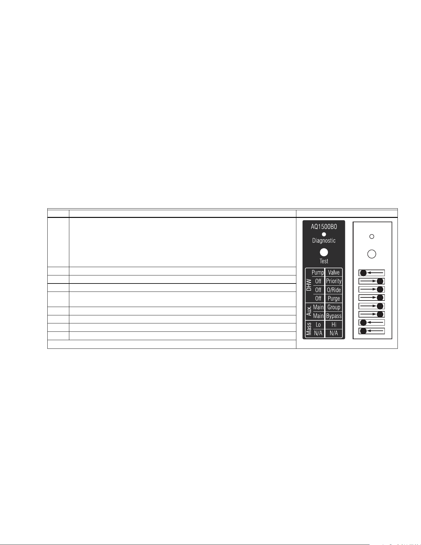
Table 2. AQ1500B0 Control Module DIP switch arrangement
DIP # Switch Description Label and Factory Settings
1 DHW Device - Pump or Valve
2 DHW Priority - OFF or Priority
3 DHW Priority Override - OFF or Override
4
Boiler post purge location – “Purge” = DHW tank first, then zones;
“OFF” = zones only.
5 Aux output: “Main” = default; “Group” = group pump
6 Aux output: “Main” = default; “Bypass” = boiler bypass pump
7 Load Mass: “Lo” = Low mass (baseboard); “Hi” = High mass (radiant slab)
8 Not used at this time
M23719
Test
Diagnostic
Test
Diagnostic
M23721
AQ250 SERIES HYDRONIC CONTROL PANELS
69-1982 12
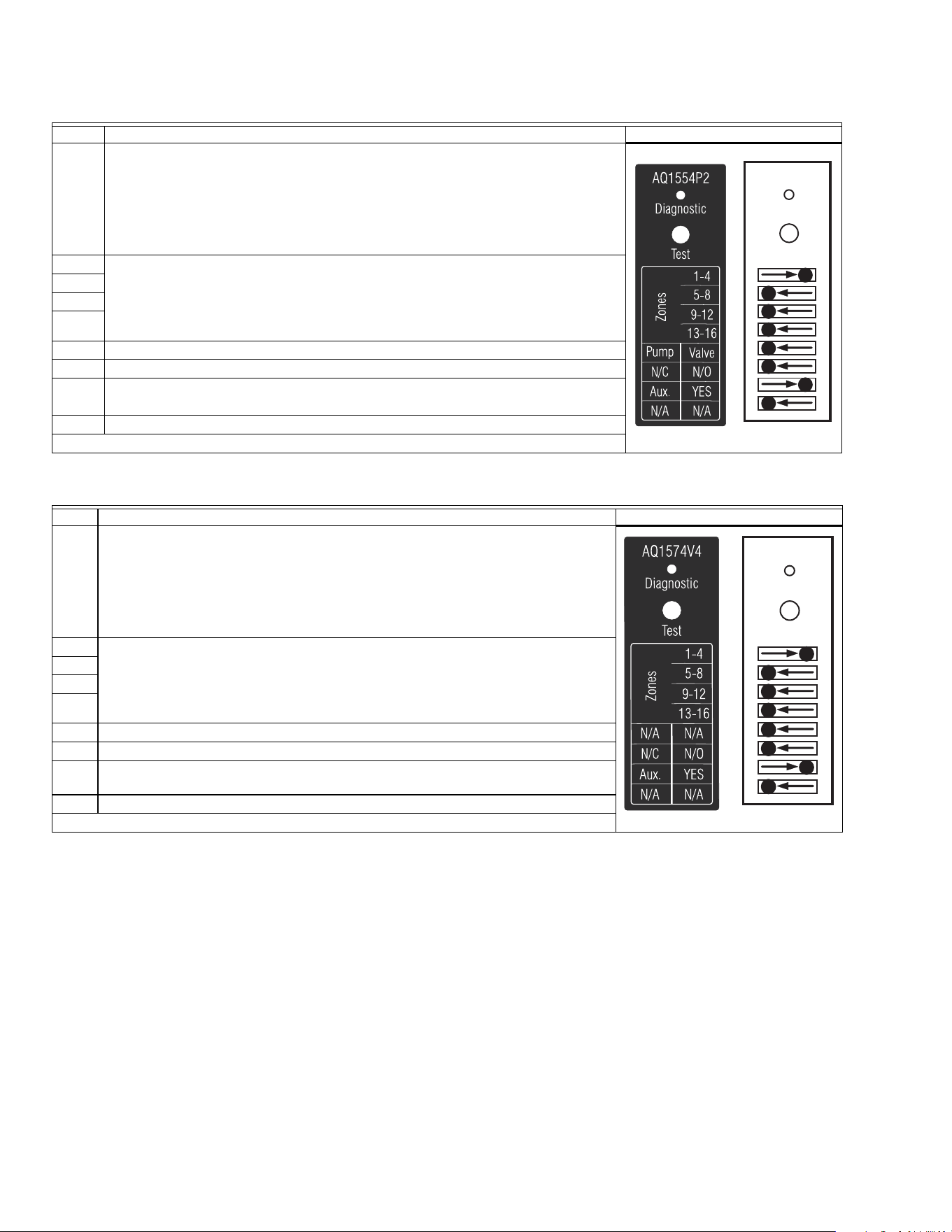
Table 3. AQ1554P2 Zoning Module (Pump Zoning Module) DIP switch arrangement
* The AQ1500B0 Boiler Control Module DIP switch #5 must be set to “GROUP” position and DIP switch #6 must be set to “MAIN” position.
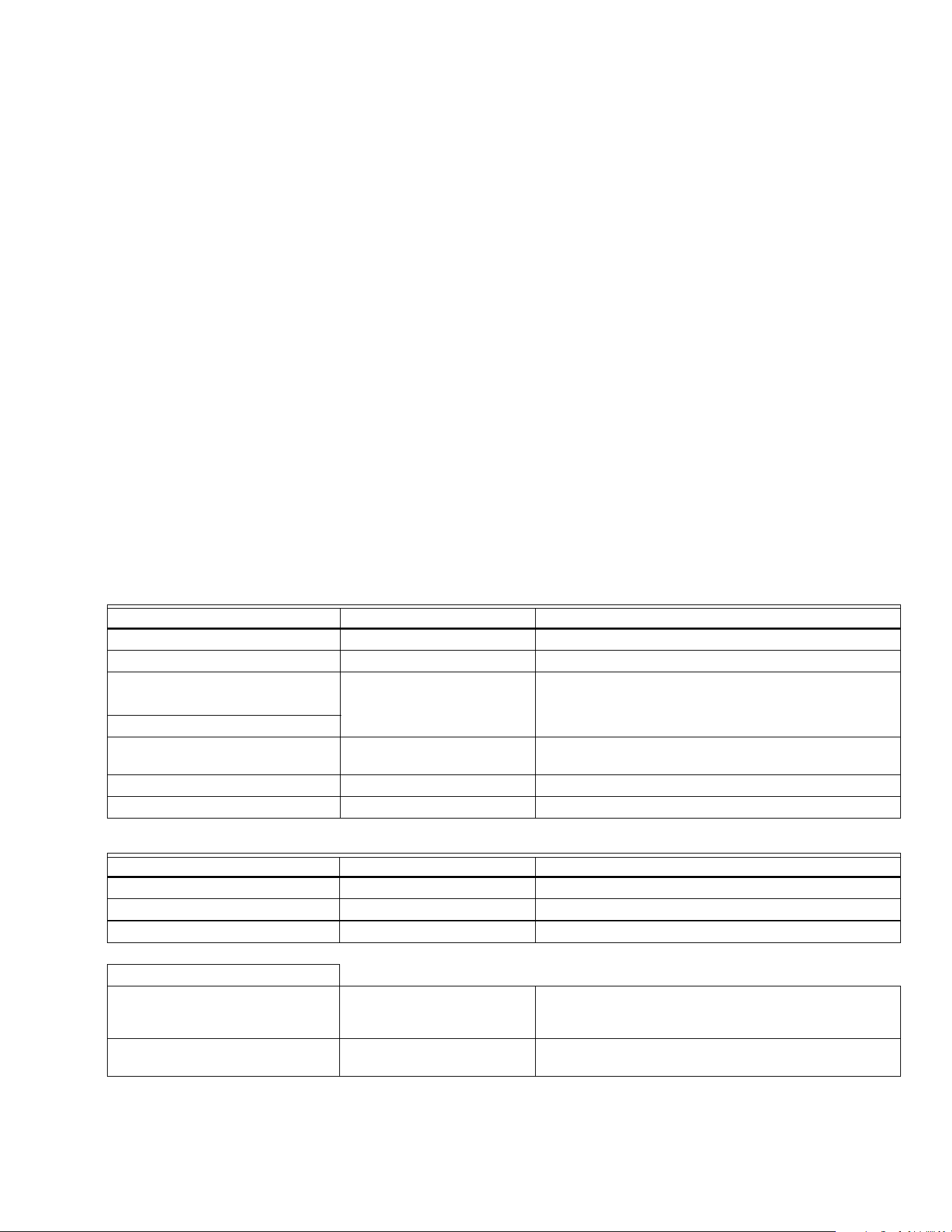
Table 4. AQ1574V4 Zoning Module (Valve Zoning Module) DIP switch arrangement
* The AQ1500B0 Boiler Control Module DIP switch #5 must be set to “GROUP” position and DIP switch #6 must be set to “MAIN” position.
8 Test and Check Out the Installation
Startup
Apply power to the AQ250 Control Panel ONLY AFTER all of
the AQ2000 SERIES components (Control Panel,
thermostats, sensors, Zoning Modules / Panels) have been
wired to the other components in the hydronic heating system
(boiler, zone valves or pumps, DHW AQUASTAT, etc.).
Once powered, the AQ250 Control Panel will begin its start-up
routine, establishing communication with all other AQ2000
SERIES components on the AQUATROL network.
Test
A) AUTO TEST—AQ1500B0 CONTROL MODULE
Auto Test operation enables the installer to test the system
installation by sequentially activating all of the Control
Module's outputs for 15 seconds each. Each step of the Auto
Test routine may be paused or skipped by pressing the Test
button.
STATUS LEDS
Every status light (ZR, BOILER pump, AUXiliary pump, DHW
pump) will be turned on for 15 seconds when its
corresponding output is energized during Auto Test.
DIP # Switch Description Label and Factory Settings
1Zone Address
For each group of 4 zones, there can be only one DIP switch in the right hand position. The
first Zoning Module connected to each Control Module must have the first of these DIP
switches (“1-4”) set to the right hand position with the other 3 switches set to the left. The
second Zoning Module’s “5-8” switch must be in the right hand position; the third Zoning
Module’s “9-12” switch must be in the right hand position, etc.
2
3
4
5 Zoning with valves or pumps
6 Are zone valves normally closed (N.C.) or normally open (N.O.)
7
If set to “YES”, AUX Pump contacts (on Control Module) are switched when any of
the zones on this Zoning Module are active*
8 Not used at this time
DIP # Switch Description Label and Factory Settings
1 Zone Address
For each group of 4 zones, there can be only one DIP switch in the right hand position. The
first Zoning Module connected to each Control Module must have the first of these DIP
switches (“1-4”) set to the right hand position with the other 3 switches set to the left. The
second Zoning Module’s “5-8” switch must be in the right hand position; the third Zoning
Module’s “9-12” switch must be in the right hand position, etc.
2
3
4
5 Not used at this time
6 Are zone valves normally closed (N.C.) or normally open (N.O.)
7
If set to “YES”, AUX Pump contacts (on Control Module) are switched when any of
the zones on this Zoning Module are active*
8 Not used at this time
M23720
Diagnostic
Test
Diagnostic
Test
M23714
M23716
Diagnostic
Test
Diagnostic
Test
M23714

AQ250 SERIES HYDRONIC CONTROL PANELS
13 69-1982
DIAGNOSTIC LED
This light is used by the AQ250 to communicate diagnostic
data to the user:
• Constantly ON indicates that the unit is working properly.
• Constant, fast blinking indicates that the unit is in the Auto
Test mode; constant, slow blinking indicates that Auto Test
mode has been paused
• Coded blinking is used to communicate an error code to
the user. Refer to the Troubleshooting section of these
instructions for an explanation of these codes.
NOTE: The Diagnostic LED is OFF when the AQ250 Control
Panel is not powered.
If this is the first time the AQ250 has been started:
1. Remove the front cover of the AQ250 by loosening the
4 captive slot-Phillips screws.
2. Remove the AQ1500B0 Control Module’s DIP switch
cover (refer to Figure 15 for the DIP switch cover loca-
tion)
3. Check to make sure that the LED labelled “Diagnostic”
is steadily illuminated (no blinking)
4. To begin the Auto Test press on the “Test” button until
you feel a “click”. The AQ250 will now begin the Auto
Test routine and the Diagnostic LED on the AQ1500B0
Control Module will blink quickly.
5. Pressing the Test button at any time during the Auto
Test routine will pause the routine indefinitely. While
paused, the Diagnostic LED blinks slowly
6. Pressing the Test button while the Auto Test routine is
paused will advance the routine to the start of the next
step in the routine (testing the next output) and the Auto
Test routine will resume its test procedure.
7. When the Auto Test routine is completed, the Diagnostic
LED returns to a constant ON status (no blinking).
8. To test each of the zone outputs (pumps or valves) indi-
vidually, proceed to Section B) below to run the Auto
Test feature for each AQ155 / AQ157 Zoning Module
attached to the AQ1500B0 Control Module.
SEQUENCE OF OPERATION—AQ1500B0 CONTROL MODULE
1. When the Test button is pressed, ALL space heating
zones connected to the Control Module are energized
and remain energized for the duration of the Auto Test
routine
2. At the same time, the “Diagnostic” LED on the
AQ1500B0 Control Module begins to blink quickly and
the “ZR” relay is energized for 15 seconds, then shuts
off
3. Following that, the “BOILER” relay is energized for 15
seconds, then shuts off
4. Following that, the “AUX” relay is energized for 15 sec-
onds, then shuts off
5. Following that, the “DHW” relay is energized for 15 sec-
onds, then shuts off
6. Following that, the “Boiler” T-T dry contacts are ener-
gized for 15 seconds, then re-opened
7. Following that, AQ1500B0 exits the Auto Test routine
and the “Diagnostic” LED on the Module returns to
steady illumination (no blinking)
B) AUTO TEST - AQ155 / AQ157 ZONING MODULES
Auto Test operation for Zoning Modules enables the installer
to test all zones wired to the Zoning Module by sequentially
activating the equipment connected to each zone output
(pump or valve) for 15 seconds. Each step of the Auto Test
routine may be paused or skipped by pressing the Test button.
ZONING MODULE DIAGNOSTIC LED
The LED labeled “DIAGNOSTIC”—located above the DIP
switches on the AQ155 / AQ157 Zoning Modules - is used for
communicating diagnostic data to the Installer.
Refer to the Troubleshooting Section of this Quick Start
Manual for a description of the Diagnostic LED error codes
(blinking rates).
NOTE: The Diagnostic LED is OFF when the AQ155 /
AQ157 Zoning Module is not powered.
If this is the first time the AQ250 Control Panel has been
started:
1. With the front cover of the AQ250 Control Panel
removed and set aside, remove the AQ Zoning Module
DIP switch cover (refer to Figure 15 for the DIP switch
cover location)
2.
Check to make sure that the LED labelled “Diagnostic”
is steadily illuminated (no blinking)
3. Press on the “Test” button until you feel a “click”. The
AQ155 / AQ157 Zoning Module will now begin the Auto
Test routine, and the Diagnostic LED on the Zoning
Module will blink quickly
4. Pressing the Test button at any time during the Auto
Test routine will pause the routine indefinitely. While
paused, the Diagnostic LED blinks slowly
5. Pressing the Test button while the Auto Test routine is
paused will advance the routine to the start of the next
step in the routine (testing the next zoning output) and
the Auto Test routine will resume its test procedure
6. When the Auto Test routine is completed, the Diagnostic
LED returns to a constant ON status (no blinking).
7. Replace the DIP switch cover on the Zoning Module
8. Repeat Steps 1-7 for every other AQ155 / AQ157 Zon-
ing Module connected to the AQ250
SEQUENCE OF OPERATION—AQ155 / AQ157 ZONING MODULES
1. When the Auto Test button is pressed, Zone 1 of the
Zoning Module is energized and the “Diagnostic” LED
on the AQ155 / AQ157 begins to blink quickly. Zone 1
remains energized for 15 seconds, then shuts off
2. Following that, each of the remaining zones is ener-
gized, sequentially—starting with Zone 2—for 15 sec-
onds, and then shuts off.
3. After Zone 4 has been de-energized, the AQ155 /
AQ157 exits the Auto Test routine and the “Diagnostic”
LED on the Module returns to steady illumination (no
blinking)
If no errors were detected in the Control Module or Zoning
Module Auto Test routines, the AQ250 is now ready for
operation. If errors were detected, refer to the Troubleshooting
section in the Appendix of these Instructions.
Check Out
1. Turn down the DHW AQUASTAT, if present, to avoid
interfering with space heating control operation.
2. Turn up the set point of one of the AQ1000 zone ther-
mostats.
2.1 The zone valve or pump associated with that zone
will turn on.
2.2 The Boiler, and T-T relay outputs will energize.

AQ250 SERIES HYDRONIC CONTROL PANELS
69-1982 14
NOTE: When a setpoint is changed on an AQ1000
thermostat, the AQ250’s boiler short cycle pro-
tection is disabled in favor of a faster reaction
for the user
3. Turn down the set point of one of the AQ1000 zone
thermostats.
3.1 The zone valve or pump associated with that zone
should turn off.
3.2 The Boiler, and T-T relay outputs should de-
energize.
4. Repeat steps 2 and 3 for all zones to verify each zone is
operating correctly. Thermostats may be exercised indi-
vidually or all together to accelerate the check out pro-
cess.
5. Turn up the DHW AQUASTAT to simulate a call for hot
water.
5.1 If the DHW device is a pump, the DHW relay output
will be energized immediately. The Boiler pump
relay will remain off.
5.2 If the DHW device is a valve, the Boiler pump relay
will come on after a 15 second delay to allow the
zone valve to fully open.
5.3 Turn up the set point of one of the AQ1000 zone
thermostats.
5.3.1 If the DHW relay is configured to control a
pump, and DHW Priority is selected, the
Boiler and associated zone pumps relays will
remain off.
5.3.2 If the DHW relay is configured to control a
valve, and DHW Priority is selected, the
associated zone relays will remain off.
5.3.3 If DHW Priority is disabled, space heating
(zone pumps and valves) will operate
normally even during a call for DHW.
Turn down the DHW AQUASTAT to end the call for hot water.
Space heating operation will continue (if DHW priority is
disabled) or resume (if DHW priority is enabled).
9 Purge Air From All System and Zone
Piping using the built-in Purge
Routine feature
Purging air from all zones in the hydronic system can be
easily accomplished with the AQ250 by using a modification
to the “Auto Test” feature (described in section 8A) as follows:
• To purge all zones on the AQUATROL network press the
“Test” button on the AQ1500B0 Control Module once to
begin the “Auto Test” routine. Quickly press it again 3 times
until the Boiler relay LED is illuminated AND the
“Diagnostic” LED of the AQ1500B0 is blinking slowly
(indicating the Auto Test routine has been paused). The
boiler pump will now remain energized for the duration of
the Purge routine (and therefore be purging all loops of air)
until the “Test” button is pressed again.
• The “DIAGNOSTIC” LED will blink slowly while in paused
mode. Continue to purge the boiler loop as long as is
needed to remove air from the system.
• Leaving the boiler pump operating, push the Test button on
the Zoning Module for any space heating zones you wish
to purge. With the first zone's output energized (the LED
for Zone 1 will be illuminated), press the test button again
to pause the Auto Test routine. When Zone 1 has been
sufficiently purged, press the Test button again to begin
purging Zone 2. Again, press the Test button to pause the
Auto Test routine while purging Zone 2. Continue to purge
all other space heating zones in the system.
If additional purging is required for any zone, the Auto Test
procedure can be activated for any individual Zoning Module
by pressing the “Test” button located above that Zoning
Module’s DIP switches. Refer to the Sequence of Operation in
the preceding section (“Auto Test—AQ155 / AQ157 Zoning
Modules”)
10 Document and Keep A Record Of All
System Settings
Once the hydronic installation with the AQ250 Control Panel
has been set up and is operating properly, it’s important to
document all the system settings for future reference.
To facilitate this, all AQ2000 Series Control Panels and
Expansion Zoning Panels are shipped with Installation
Records for documenting these settings. These should be
filled out completely and saved in the Installing Contractor’s
files.
AQ250 SERIES HYDRONIC CONTROL PANELS
15 69-1982
APPENDIX
Troubleshooting
Communications Loss
A possible failure mode of the AQ250 would be loss of
communication between the Control Module and any Zoning
Modules or between a Zoning Module and any zone
thermostats that have previously been connected to the
AQUATROL network. In general, the Control will:
• Periodically try to re-establish communication with any
“lost” components on the network;
• Initialize any component that re-establishes its
communication.
CONTROL MODULE REACTION
When the AQ1500B0 Control Module loses communication
with any number of zones (as long as there’s still at least one
zone communicating on the AQUATROL network), the AQ250
will continue to deliver heat to the other communicating zones.
When communication is lost with ALL zones, the AQ250
enters FREEZE PROTECTION mode in which it fires the
boiler and then activates the BOILER pump for a period of 4
minutes every hour. This should provide sufficient heat to the
system to prevent a building from freezing up until someone
re-establishes the communication between the AQ2000
components.
ZONING MODULE REACTION
When a Zoning Module loses communication with the Control
Module, the Zoning Module operates its pumps or valves in a
“conventional, non-synchronized” zoning fashion i.e.
according to the demands from the thermostats, without
waiting for the “permission” from the AQ1500B0 Control
Module to operate. This allows the zones to extract any heat
provided by the boiler.
When communication is lost between a Zoning Module and
one of its thermostats, that zone is “invisible” to the Control
Module; the Zoning Module stops serving that zone and the
zone’s pump or valve is de-energized.
The AQ250 provides Control Module diagnostic information
via the DIAGNOSTIC LEDs located above the DIP switches
on the AQ1500B0 Control Module.
The AQ250 provides Zoning Module diagnostic information
via the DIAGNOSTIC LEDs located above the DIP switches
on its Zoning Module(s).
This information helps the installer correctly identify system
problems, making troubleshooting much faster. The following
tables describe the possible error codes that can be displayed
on the AQ1500B0 Control Module and AQ155 / AQ157
Zoning Modules.
Table 5. AQ1500B0 Control Module Error Codes:
Table 6. AQ155 / AQ157 Zoning Module Error Codes:
DIAG LED Status System Condition Action Required
Steady (no blinking) No system problem detected None
Fast blinking (4 blinks / second) Auto Test is in operation None. Permit the control to finish Auto Test routine
Slow blinking (2 blinks / 3 seconds) Auto Test has been “paused” Press the Test button to resume Auto Test r o u ti n e
Coded blinking = ERROR
• 2 blinks then pause Freeze protection activated
across AQUATROL network
All zones have lost communication with controller – check
B-B wiring between Control Module and Zoning Module
• 4 blinks then pause Return sensor open / short Check the return sensor wiring
• 5 blinks then pause Supply sensor open / short Check the supply sensor wiring
DIAG LED Status System Condition Action Required
Steady (no blinking) No system problem detected None
Fast blinking (4 blinks / second) Auto Test is in operation None. Permit the control to finish Auto Test routine
Slow blinking (2 blinks / 3 seconds) Auto Test has been “paused” Press the Test button to resume Auto Test routine
Coded blinking = ERROR
• 2 blinks then pause Freeze protection activated on
the Zoning Module
Zoning module has lost communication with controller –
check B-B wiring between Control Module and Zoning
Module
• 3 blinks then pause Communication lost with ALL
thermostats
Check thermostat wiring to Zoning Modules

AQ250 SERIES HYDRONIC CONTROL PANELS
Automation and Control Solutions
Honeywell International Inc. Honeywell Limited-Honeywell Limitée
1985 Douglas Drive North 35 Dynamic Drive
Golden Valley, MN 55422 Toronto, Ontario M1V 4Z9
customer.honeywell.com
® U.S. Registered Trademark
© 2007 Honeywell International Inc.
69-1982 C.H. 11-07