Loading ...
Loading ...
Loading ...
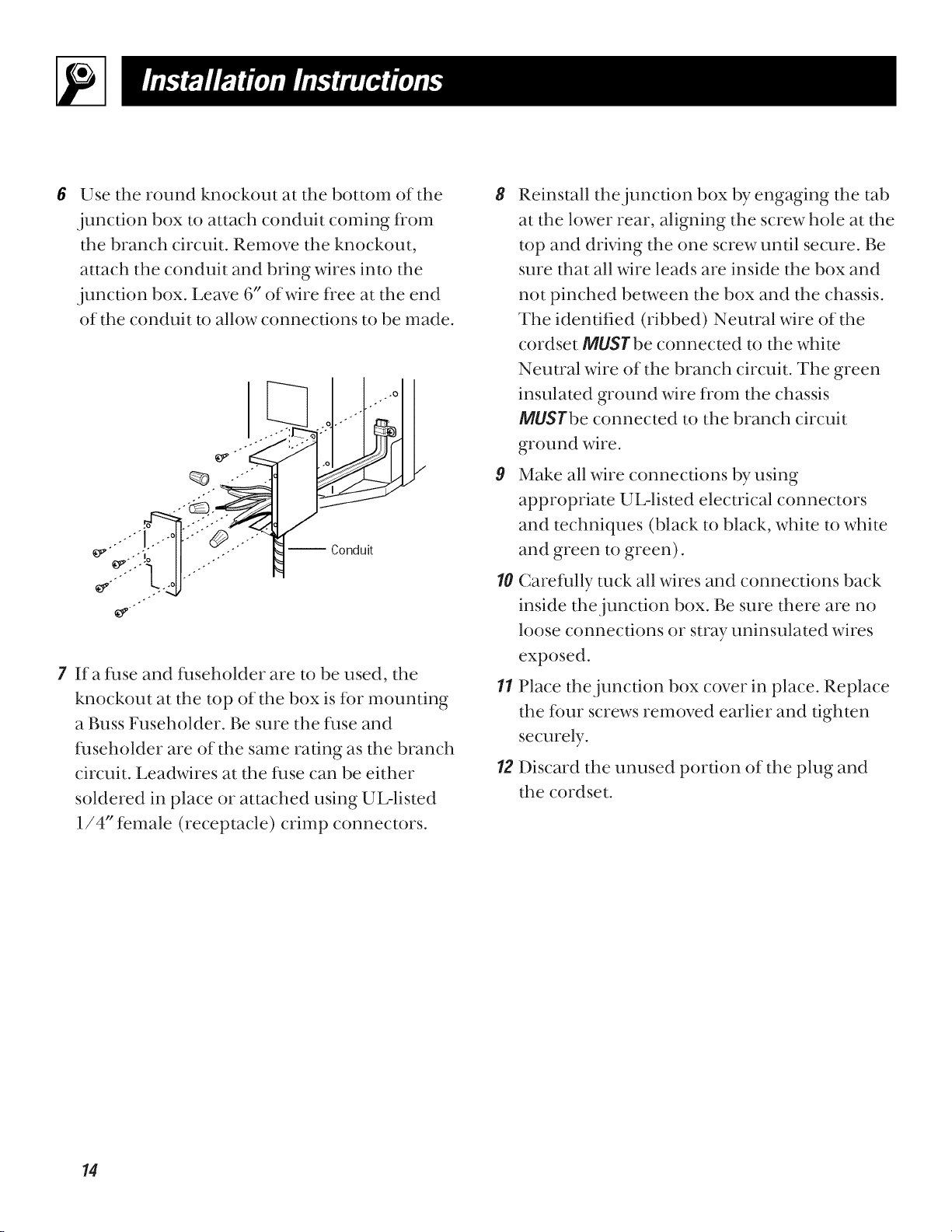
Use the round knockout at the bottom of the
junction box to attach conduit coming from
the branch circuit. Remove the knockout,
attach the conduit and bring wires into the
junction box. Leave 6" of wire free at the end
of the conduit to allow connections to be made.
7 Ifa fl_se and fl_seholder are to be used, the
knockout at the top of the box is for mounting
a Buss Fuseholder. Be sure the fl_se and
fl_seholder are of the same rating as the branch
circuit. Leadwires at the fl_se can be either
soldered in place or attached using UL-listed
1/4" female (receptacle) crimp connectors.
8 Reinstall the junction box by engaging the tab
at the lower rear, aligning the screw hole at the
top and driving the one screw until secure. Be
sure that all wire leads are inside the box and
not pinched between the box and the chassis.
The identified (ribbed) Neutral wire of the
cordset MUSgbe connected to the white
Neutral wire of the branch circuit. The green
insulated ground wire from the chassis
MUSl'be connected to the branch circuit
ground wire.
9 Make all wire connections by using
appropriate UL-listed electrical connectors
and techniques (black to black, white to white
and green to green).
10 Careflflly rock all wires and connections back
inside the junction box. Be sure there are no
loose connections or stray uninsulated wires
exposed.
11 Place the junction box cover in place. Replace
the fimr screws removed earlier and tighten
securely.
12 Discard the unused portion of the plug and
the cordset.
14
Loading ...
Loading ...
Loading ...