Loading ...
Loading ...
Loading ...
English 9
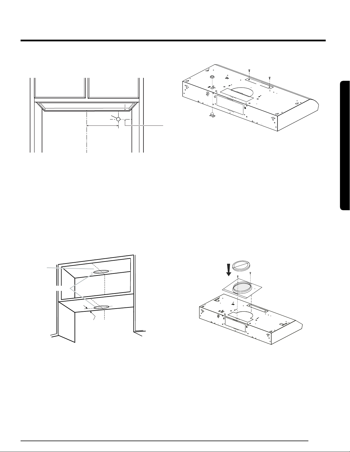
To wire through wall:
1. Mark a line distance (A) from the right of the centerline on the
underside of the cabinet. Mark the point on this line that is
7
⁄8″ (2.2 cm)
from the underside of the cabinet. Drill a
7
⁄8″ (2.2 cm) diameter hole (B)
through the rear wall at this point.
B
A
7⁄8”
(2.2 cm)
A. 8 2/5" (21.3cm)
Mark and Cut Vent Opening
For a non-vented (recirculating) installation: skip "Mark and Cut Vent
Opening" step.
For 7" (17.8 cm) Round Vent System (Roof Venting)
To make a circular vent opening on the underside of the cabinet top:
1. Mark a centerline on the underside of the top of cabinet.
2. Mark a line 5” (12.8 cm) from the back wall on the underside of the top
of cabinet.
3. Use a compass or a circle template to draw a circle with a diameter of
7½” (19 cm).
4. Use saber or keyhole saw to cut the circular vent opening. Repeat
steps 1-3 for the underside of the top of the cabinet.
Cabinet cutouts
*From wall, not cabinet frame
*5”
(12.8 cm)
C
enterline
Drill Electrical Opening
1. Using a 1¼" (3 cm) drill bit, drill the hole in the dot marked previously
at the electrical strain relief.
Prepare Range Hood Vents
A
B
C
D
E
Install Strain Relief
1. Install a UL listed/CSA approved ½" (13 mm) strain relief (A).
For non-vented (Recirculating) Installations
Remove the (2) T10 Torx® screws and remove the top, front rectangular
vent cover (E). Go to “Electrical Connection” step.
When used in recirculation mode, To Reduce the Risk of Fire and Shock
use only conversion kit model XXXXXXXX.
Attach Vent Damper or Transition
1. Uninstall the 7" (17.8 cm) round vent mounting plate (A) located over
the vent knockouts.
2. Remove both top knockouts (C and D).
3. Place the round transition over the removed vent knockouts and place
the screws again.
If installing the optional round damper, position it over the round vent
mounting plate. Round damper (Code Number: XXXXXXXX.) is not
included in the product,so please purchase it through the service center.
Consult "Use and Care" section on this manual for assistance.
Installation Instructions
Installation Instructions
Loading ...
Loading ...
Loading ...