Operator's Manual
CRRFr MRN
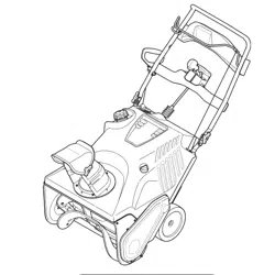
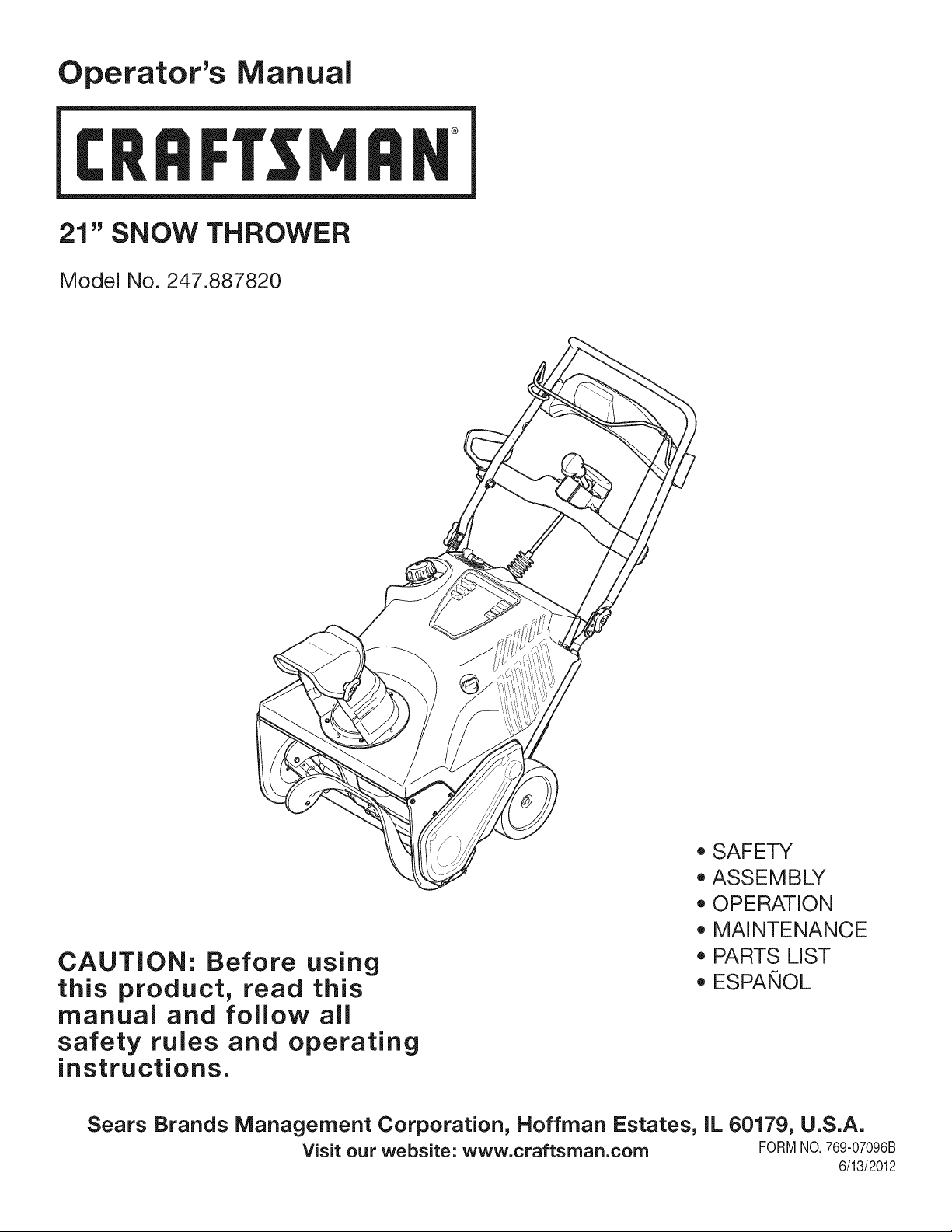
21" SNOW THROWER
Model No. 247.887820
CAUTION: Before using
this product, read this
manual and follow all
safety rules and operating
instructions.
o SAFETY
ASSEMBLY
OPERATION
MAINTENANCE
PARTS LIST
o ESPANOL
Sears Brands Management Corporation, Hoffman Estates, IL 60179, U.S.A.
Visit our website: www.craftsman.com FORM1/O.769-07096B
6/13/2012
Warranty Statement .................................. Page 2
Safe Operation Practices .......................... Pages 3-6
Assembly .................................................. Pages 7-10
Operation .................................................. Pages 11-13
Service and Maintenance ......................... Pages 14-18
Off-Season Storage .................................. Page 19
Troubleshooting ........................................ Page 20
Parts List ..................................................... Pages 22-33
Labels ....................................................... Page 34
Repair Protection Agreement ................... Page 39
Espa_ol ..................................................... Page 40
Service Numbers ...................................... Back Cover
CRAFTSMAN TWO YEAR FULL WARRANTY
FORTWOYEARSfromthe dateof purchase,this productis warrantedagainstanydefectsin materialor workmanship.Defectiveproductwill
receivefree repairor free replacementif repairis unavailable,
Thiswarrantyis void if thisproductis everusedwhile providingcommercialservicesor if rentedto anotherperson,
For warrantycoverage details to obtain repairor replacement,visit the website: www.craftsman.com
This warranty covers ONLYdefects in material andworkmanship. Warranty coverage does NOTinclude:
• Expendableitemsthatcan wearoutfromnormalusewithinthewarrantyperiod,includingbut not limitedto augers,augerpaddles,drift
cutters,skidshoes,shaveplate,shearpins,sparkplug,air cleaner,belts,andoil filter.
• Standardmaintenanceservicing,oil changes,or tune-ups.
• Tire replacementor repaircausedby puncturesfromoutsideobjects,suchas nails,thorns,stumps,or glass.
• Tireor wheelreplacementor repairresultingfromnormalwear,accident,orimproperoperationor maintenance.
• Repairsnecessarybecauseof operatorabuse, includingbutnot limitedto damagecausedby over-speedingthe engine,or fromimpacting
objectsthat bendthe frame,augershaft,etc.
• Repairsnecessarybecauseof operatornegligence,includingbut not limitedto,electricalandmechanicaldamagecausedby improper
storage,failureto usethe propergradeandamountof engineoil, or failureto maintainthe equipmentaccordingto the instructionscontained
inthe operator'smanual.
• Engine(fuelsystem)cleaningor repairscausedbyfuel determinedto becontaminatedoroxidized(stale).In general,fuel shouldbeused
within30 daysof itspurchasedate.
• Normaldeteriorationandwearof the exteriorfinishes,or productlabelreplacement.
Thiswarrantygivesyou specificlegalrights,andyou mayalso haveotherrightswhichvaryfromstateto state.
Sears Brands Management Corporation, Hoffman Estates, IL 60179
EngineOilType: SAE5W-30
EngineOilCapacity: 20ounces
FuelCapacity: 2 Quarts
SparkPlug: F6RTC
SparkPlugGap: .020"-.030"
ModelNumber.................................................................
Serial Number .................................................................
Dateof Purchase.............................................................
Recordthe modelnumber,serialnumber
anddateof purchaseabove
© Sears Brands,LLC
2
Thissymbolpointsout importantsafetyinstructionswhich,if not
followed,couldendangerthepersonalsafetyand/orpropertyof
yourselfandothers. Readandfollowall instructionsin this manual
beforeattemptingto operatethismachine.Failureto complywith
theseinstructionsmay resultin personalinjury.Whenyou seethis
symbol,HEEDITSWARNING!
CALIFORNIA PROPOSITION 65
EngineExhaust,someof itsconstituents,and certainvehicle
componentscontainoremitchemicalsknownto Stateof California
to causecancerandbirthdefectsorotherreproductiveharm,
Thismachinewasbuiltto beoperatedaccordingto the safeopera-
tion practicesinthis manual.As withanytypeof powerequipment,
carelessnessorerroron the partof the operatorcan resultin serious
injury.Thismachineis capableof amputatingfingers,hands,toes
andfeetandthrowingdebris.Failureto observethe followingsafety
instructionscouldresultin seriousinjuryor death.
Your Responsibility--Restrict the use of thispowermachineto
personswho read,understandandfollowthewarningsand instruc-
tionsin thismanualandon the machine,
SAVE THESE INSTRUCTIONS!
TRAiNiNG
• Read,understand,and followall instructionson the machineand
in themanual(s)beforeattemptingto assembleandoperate.
Failureto do socan resultinseriousinjuryto the operatorand/
orbystanders.Keepthismanualin a safeplaceforfutureand
regularreferenceandfor orderingreplacementparts.Toorder
replacementpartscall,1-800-4MY-HOME.
• Befamiliarwithall controlsandtheir properoperation.Knowhow
to stopthe machineanddisengagethemquickly.
• Neverallowchildrenunder 14 yearsof age to operatethis
machine.Children14andover shouldreadand understandthe
instructionsandsafe operationpracticesin this manualand on
the machineandbe trainedand supervisedby an adult.
Neverallowadultsto operatethis machinewithoutproper
instruction.
• Thrownobjectscan causeseriouspersonalinjury.Planyour
snow-throwingpatternto avoiddischargeof materialtoward
roads,bystandersandthe like.
Keepbystanders,pets and childrenat least75 feet from the
machinewhile it is in operation.Stopmachineif anyoneenters
the area.
• Exercisecautionto avoidslippingor falling,especiallywhen
operatingin reverse.
PREPARATION
Thoroughlyinspecttheareawherethe equipmentisto beused.
Removeall doormats,newspapers,sleds,boards,wiresand other
foreignobjects,whichcouldbe trippedoverorthrownby the auger/
impeller.
• Alwayswear safetyglassesor eyeshieldsduringoperationand
while performingan adjustmentor repairto protectyoureyes.
Thrownobjectswhichricochetcancause seriousinjuryto the
eyes.
Donot operatewithoutwearingadequatewinteroutergarments.
Donot wearjewelry,longscarvesorotherlooseclothing,which
could becomeentangledin movingparts.Wearfootwearwhich
will improvefootingonslipperysurfaces.
Usea groundedthree-wireextensioncordand receptaclefor all
machineswithelectricstartengines.
Disengageall controlleversbeforestartingthe engine.
• Neverattemptto make anyadjustmentswhileengineis running,
exceptwherespecificallyrecommendedinthe operator'smanual.
Letengineandmachineadjustto outdoortemperaturebefore
startingto clearsnow.
3
Safe Handling of Gasoline
Toavoidpersonalinjuryor propertydamageuseextremecare in
handlinggasoline.Gasolineis extremelyflammableand the vaporsare
explosive.Seriouspersonalinjurycan occurwhengasolineis spilled
onyourselfor yourclotheswhichcan ignite. Washyour skinand
changeclothesimmediately.
• Useonlyan approvedgasolinecontainer.
• Extinguishall cigarettes,cigars,pipesand other sourcesof
ignition.
• Neverfuel machineindoors.
• Neverremovegas capor addfuel whilethe engineis hot or
running.
• Allowengineto coolat leasttwo minutesbeforerefueling.
• Neveroverfillfuel tank.Filltankto nomorethan1/2inchbelow
bottomof filler neckto providespaceforfuel expansion.
• Replacegasolinecapand tighten securely.
• Ifgasolineis spilled,wipe it off theengineandequipment.Move
machineto anotherarea.Wait5 minutesbeforestartingthe
engine.
• Neverstorethe machineorfuel containerinsidewherethereis an
openflame,sparkor pilotlight(e.g.furnace,waterheater,space
heater,clothesdryeretc.).
• Allowmachineto cool at least5 minutesbeforestoring.
• Neverfill containersinsidea vehicleor ona truckor trailerbed
witha plasticliner.Alwaysplacecontainerson the groundaway
fromyour vehiclebeforefilling.
• If possible,removegas-poweredequipmentfromthe truckor
trailerandrefuelit onthe ground.Ifthis is not possible,then refuel
suchequipmenton a trailerwitha portablecontainer,ratherthan
froma gasolinedispensernozzle.
• Keepthe nozzlein contactwiththe rimof the fuel tankor
containeropeningat alltimes untilfuelingis complete.Do not use
a nozzlelock-opendevice.
OPERATION
• Do not puthandsorfeetnear rotatingparts,in the auger/impeller
housingor chuteassembly.Contactwith the rotatingpartscan
amputatehandsand feet.
• Theauger/impellercontrolleveris a safetydevice.Neverbypass
itsoperation.Doingso makesthe machineunsafeandmay cause
personalinjury.
• Thecontrol leversmustoperateeasilyin bothdirectionsand
automaticallyreturnto the disengagedpositionwhenreleased.
• Neveroperatewith a missingor damagedchuteassembly.Keep
all safetydevicesin placeand working.
• Neverrunanengine indoorsor in a poorlyventilatedarea. Engine
exhaustcontainscarbonmonoxide,an odorlessand deadlygas.
• Do notoperatemachinewhileunderthe influenceof alcoholor
drugs.
• Mufflerand engine becomehotand can causea burn.Do not
touch.Keepchildrenaway.
• Exerciseextremecautionwhenoperatingon or crossinggravel
surfaces.Stay alertfor hiddenhazardsor traffic.
Exercisecautionwhenchangingdirectionand whileoperatingon
slopes.
Planyoursnow-throwingpatternto avoiddischargetowards
windows,walls,carsetc. Thus,avoidingpossibleproperty
damageor personalinjurycausedby a ricochet.
Preventpossiblepropertydamageorpersonalinjuryfrom
objectricochetby planningyoursnowthrowingpatternto avoid
dischargetowardswindows,walls,cars,etc.
• Donot overloadmachinecapacityby attemptingto clearsnowat
too fastof a rate.
• Neveroperatethis machinewithoutgoodvisibility or light. Always
be sureof yourfootingand keepa firm hold on the handles.Walk,
neverrun.
• Disengagepowerto theauger/impellerwhentransportingor not
in use.
• Neveroperatemachineat high transportspeedson slippery
surfaces.Lookdownand behindand usecare whenbackingup.
• If the machineshouldstart to vibrateabnormally,stop the engine,
disconnectthe sparkplugwire andgroundit againstthe engine.
Inspectthoroughlyfor damage.Repairanydamagebefore
startingandoperating.
• Disengageall controlleversand stop enginebeforeyouleave
the operatingposition(behindthe handles).Wait untilthe auger/
impellercomesto a completestop beforeuncloggingthechute
assembly,makingany adjustments,or inspections.
• Neverput yourhand in the dischargeor collectoropenings.Do
not unclogchuteassemblywhileengineis running.Shutoff
engineand remainbehindhandlesuntilall movingparts have
stoppedbeforeunclogging.
• Useonly attachmentsand accessoriesapprovedby the manufac-
turer (e.g.wheelweights,tire chains,cabsetc.).
• Whenstartingengine,pull cord slowlyuntilresistanceis felt, then
pull rapidly.Rapidretractionof startercord(kickback)will pull
handand armtowardenginefasterthan youcan let go. Broken
bones,fractures,bruisesor sprainscould result.
• Call 1-800-4MY-HOMEfor the locationof the nearestSearsParts
& RepairServiceCenter.
CLEARING A CLOGGED DISCHARGE CHUTE
Handcontactwith the rotatingimpellerinsidethe dischargechute
is the mostcommoncauseof injuryassociatedwithsnowthrowers.
Neveruse yourhandto cleanout thedischargechute.
Toclear thechute:
1. SHUTTHEENGINEOFF!
2. Wait 10secondsto be surethe impellerbladeshavestopped
rotating.
3. Alwaysusea clean-outtool, not yourhands.
4
MAINTENANCE & STORAGE
• Nevertamperwith safetydevices.Checktheirproperoperation
regularly.Referto the maintenanceandadjustmentsectionsof
thismanual.
• Beforecleaning,repairing,or inspectingmachinedisengageall
controlleversandstop the engine.Wait untilthe auger/impeller
cometo a completestop.Disconnectthe sparkplugwireand
groundagainsttheengineto preventunintendedstarting.
Checkboltsand screwsfor propertightnessat frequentintervals
to keepthe machineinsafeworkingcondition.Also, visually
inspectmachinefor anydamage.
Do notchangetheenginegovernorsettingor over-speedthe
engine.Thegovernorcontrolsthe maximumsafeoperatingspeed
of the engine.
Snowthrowershaveplatesand skid shoesare subjectto wear
anddamage.Foryoursafetyprotection,frequentlycheckall
componentsand replacewith originalequipmentmanufacturer's
(OEM)partsonlyas listedinthe Partspagesof this Operator's
Manual.Useof partswhichdo not meetthe originalequipment
specificationsmayleadto improperperformanceandcompro-
misesafety!
Checkcontrolleversperiodicallyto verifytheyengageanddisen-
gageproperlyand adjust,if necessary.Referto the adjustment
sectioninthisoperator'smanualfor instructions.
Maintainor replacesafetyandinstructionlabels,as necessary.
Observeproperdisposallawsand regulationsfor gas,oil,etc. to
protectthe environment.
Priorto storing,run machinea few minutestoclear snowfrom
machineand preventfreezeupof auger/impeller.
Neverstorethe machineorfuel containerinsidewherethereisan
openflame,spark or pilot lightsuch as a waterheater,furnace,
clothesdryer etc.
Alwaysreferto the operator'smanualfor properinstructionson
off-seasonstorage.
Checkfuelline,tank, cap,andfittingsfrequentlyfor cracksor
leaks.Replaceif necessary.
Do notcrankenginewithsparkplug removed.
Accordingto the ConsumerProductsSafetyCommission(CPSC)
andthe U.S.EnvironmentalProtectionAgency(EPA),this product
hasan AverageUsefulLifeof seven(7) years,or 60 hoursof
operation.At the endof theAverageUsefulLifehavethe machine
inspectedannuallybyan authorizedservicedealer to ensurethat
allmechanicaland safetysystemsare workingproperlyand not
wornexcessively.Failureto do so can resultinaccidents,injuries
ordeath.
DO NOT MODIFY ENGINE
Toavoidseriousinjuryor death,do not modifyenginein any way.
Tamperingwiththe governorsettingcanleadto a runawayengineand
causeit to operateat unsafespeeds.Nevertamperwithfactorysetting
of enginegovernor.
NOTICE REGARDING EMiSSiONS
Engineswhichare certifiedtocomplywith Californiaand federal
EPAemissionregulationsfor SORE(SmallOff RoadEquipment)are
certifiedto operateon regularunleadedgasoline,and mayinclude
the followingemissioncontrol systems:EngineModification(EM),
OxidizingCatalyst(OC), SecondaryAir Injection(SAI)and ThreeWay
Catalyst(TWO)if so equipped.
SPARK ARRESTOR
Thismachineisequippedwithan internalcombustionengineand
shouldnotbe usedonor nearany unimprovedforest-covered,
brush-coveredorgrass-coveredlandunlessthe engine'sexhaust
systemisequippedwitha sparkarrestormeetingapplicablelocalor
statelaws(if any)
Ifa sparkarrestoris used,it shouldbe maintainedin effectiveworking
orderby theoperator.Inthe Stateof Californiathe aboveis required
bylaw (Section4442of the CaliforniaPublicResourcesCode).Other
statesmayhavesimilarlaws. Federallawsapplyonfederallands.
A sparkarrestorfor the muffleris availablethroughyournearestSears
PartsandRepairServiceCenter.
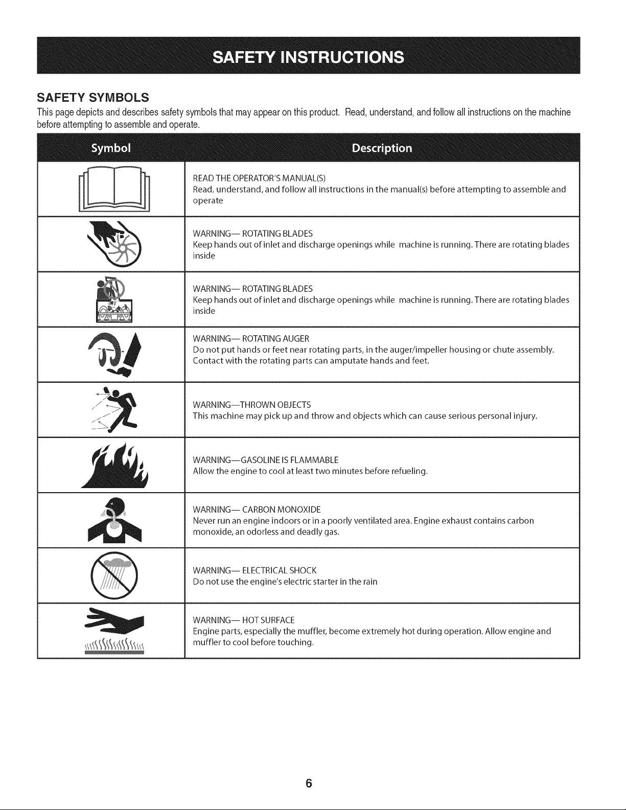
SAFETY SYMBOLS
Thispagedepictsanddescribessafetysymbolsthat mayappear on this product. Read,understand,andfollowall instructionson the machine
beforeattemptingto assembleand operate.
. +
i
i
"JIp
READ THE OPERATOR'S MANUAL(S)
Read, understand, and follow all instructions in the manual(s) before attempting to assemble and
operate
WARNING-- ROTATING BLADES
Keep hands out of inlet and discharge openings while machine is running. There are rotating blades
inside
WARNING-- ROTATING BLADES
Keep hands out of inlet and discharge openings while machine is running. There are rotating blades
inside
WARNING-- ROTATING AUGER
Do not put hands or feet near rotating parts, in the auger/impeller housing or chute assembly.
Contact with the rotating parts can amputate hands and feet.
WARNING--THROWN OBJECTS
This machine may pick up and throw and objects which can cause serious personal injury.
WARNING--GASOLINE IS FLAMMABLE
Allow the engine to cool at least two minutes before refueling.
WARNING-- CARBON MONOXIDE
Never run an engine indoors or in a poorly ventilated area. Engine exhaust contains carbon
monoxide, an odorless and deadly gas+
WARNING-- ELECTRICAL SHOCK
Do not use the engine's electric starter in the rain
WARNING-- HOT SURFACE
Engine parts, especially the muffler, become extremely hot during operation. Allow engine and
muffler to cool before touching.
6
NOTE:All referencesto the leftor rightside of the snowthrowerare
fromthe operator'sposition.Anyexceptionswill be noted.
UNPACKING THE SNOW THROWER
1. Openthe top of the carton.
2. Cut downthe cornerson the front of thecarton and folddown the
frontside.
3. Pull the snowthroweroutof the carton.Be sure notto damage
thechute,chuterotationcontrol assemblyor any cablesattached
to the chute.Someof thesepartsareshippedunderthe shroud
onthe backsideof the carton.Checkfor any cabletiessecuring
thechuteand removeif necessary.
ASSEMBLY
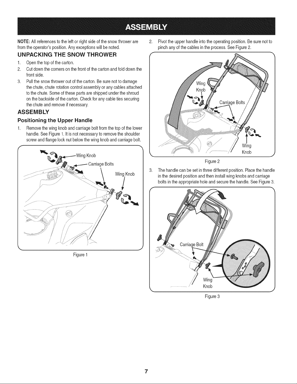
Positioning the Upper Handle
1. Removethe wing knoband carriagebolt fromthe top of the lower
handle.See Figure1. It is notnecessaryto removethe shoulder
screwandflangelocknut belowthe wingknobandcarriagebolt.
g Knob
CarriageBolts
Win(
Figure1
.J
2. Pivotthe upperhandleinto theoperatingposition.Besurenotto
pinch anyof the cablesin the process.See Figure2.
.
Wing
/ J'................... Knob
Figure2
The handlecan besetin threedifferentposition.Placethe handle
in the desiredpositionandthen installwing knobsandcarriage
boltsin the appropriateholeand securethe handle.See Figure3.
ing
Knob
Figure3
7
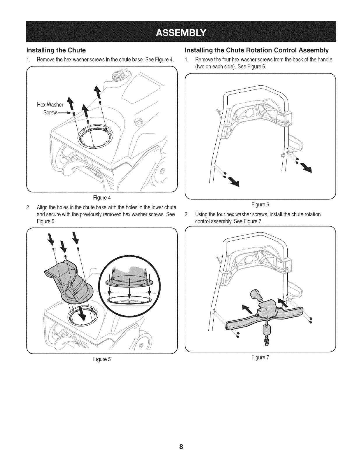
installing the Chute
1. Removethehex washerscrewsin the chute base.See Figure4.
HexWasher
Screw_,
/
/
.
Figure4
Aligntheholes inthe chutebasewiththe holesinthe lowerchute
andsecurewith the previouslyremovedhex washerscrews.See
Figure5.
Installing the Chute Rotation Control Assembly
1. Removethe fourhex washerscrewsfrom the back of the handle
(twoon eachside).See Figure6.
Figure6
Usingthefour hexwasherscrews,installthechuterotation
controlassembly.See Figure7.
Figure5
Figure7
8
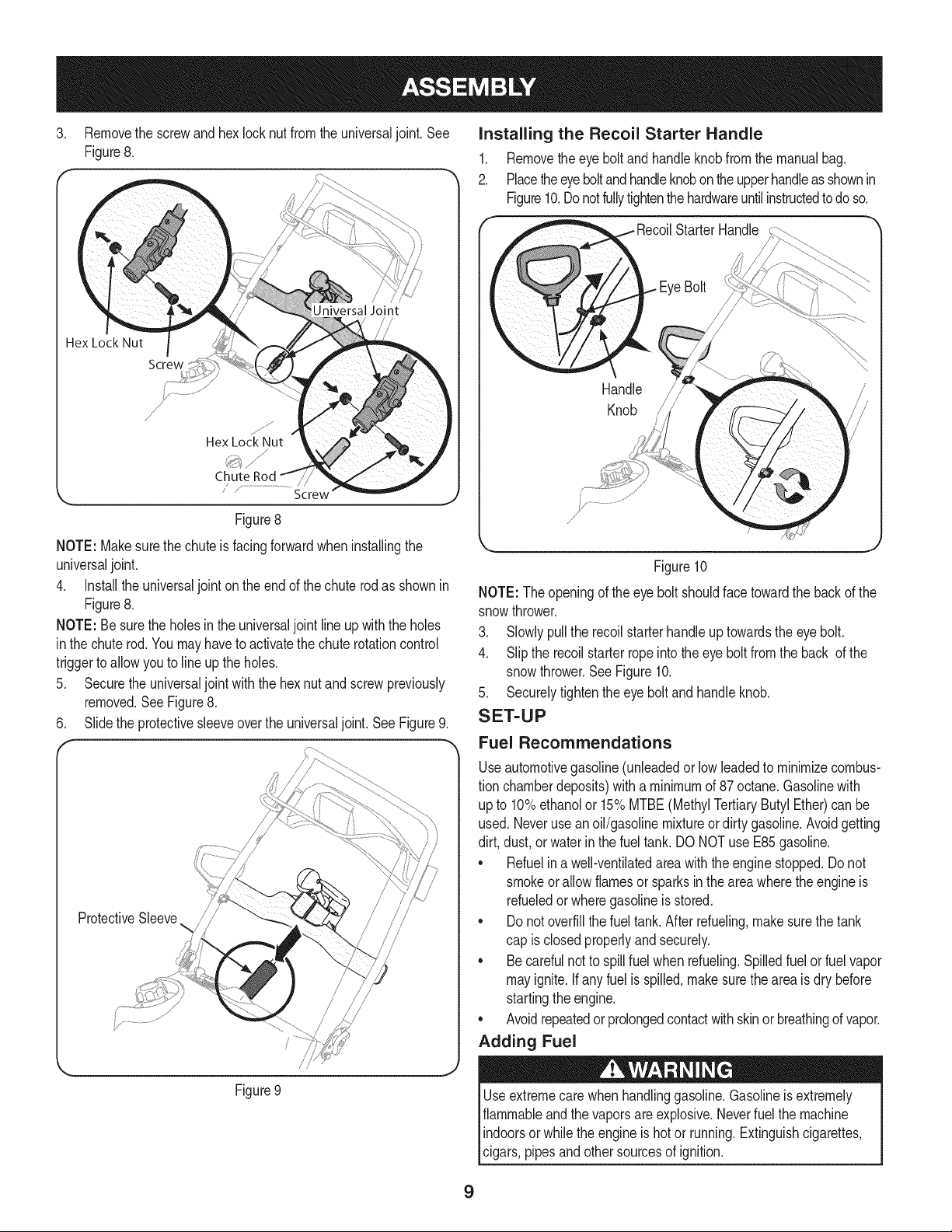
3. Removethe screwand hex lock nutfrom the universaljoint. See
Figure8.
Universal Join{
Hex Lock Nut
Screw
f
/
//
Hex Lock Nut
Chute
/ "..............................................Screw
J
Figure8
NOTE: Makesurethe chuteis facingforwardwheninstallingthe
universaljoint.
4. Installthe universaljoint on theend of thechuterodas shownin
Figure8.
NOTE: Besurethe holesinthe universaljoint lineup withthe holes
inthe chuterod.Youmayhaveto activatethechuterotationcontrol
triggerto allowyouto line upthe holes.
5. Securethe universaljoint with the hexnut and screwpreviously
removed.See Figure8.
6. Slidethe protectivesleeveoverthe universaljoint. See Figure9.
/
ProtectiveSleeve%/ ,
/
Figure9
Installing the Recoil Starter Handle
1. Removethe eyebolt and handleknobfrom the manualbag.
2. Placetheeyeboltandhandleknobonthe upperhandleas shownin
Figure10.Donotfullytightenthe hardwareuntilinstructedto doso.
Handle /
Knob
j
Figure10
NOTE: Theopeningof the eyebolt shouldfacetowardthe backof the
snowthrower.
3. Slowly pullthe recoilstarterhandle up towardsthe eyebolt.
4. Slip the recoilstarterropeinto theeye boltfrom the back of the
snowthrower.See Figure10.
5. Securelytightenthe eyebolt and handleknob.
SET-UP
Fuel Recommendations
Useautomotivegasoline(unleadedor lowleadedto minimizecombus-
tion chamberdeposits)witha minimumof 87 octane.Gasolinewith
up to 10%ethanolor 15%MTBE(MethylTertiaryButyl Ether)can be
used.Neverusean oil/gasolinemixtureor dirty gasoline.Avoidgetting
dirt, dust,or waterinthe fuel tank.DO NOTuse E85gasoline.
• Refuelin a well-ventilatedareawiththe enginestopped.Do not
smokeorallowflamesor sparksin the areawherethe engineis
refueledor wheregasolineis stored.
• Donot overfillthe fueltank.After refueling,makesurethe tank
cap is closedproperlyandsecurely.
• Be carefulnotto spillfuel whenrefueling.Spilledfuel or fuel vapor
mayignite.If any fuelis spilled,makesurethe areais dry before
startingthe engine.
• Avoidrepeatedor prolongedcontactwithskinorbreathingof vapor.
Adding Fuel
Useextremecare whenhandlinggasoline.Gasolineisextremely
flammableand thevapors are explosive.Neverfuel the machine
indoorsorwhilethe engineis hotor running.Extinguishcigarettes,
cigars,pipesandothersourcesof ignition.
9
Alwayskeephandsand feet clearof equipmentmovingparts.Do not
usea pressurizedstartingfluid. Vaporsare flammable.
1. Removethegascap, checkthefuel leveland addfuel if necessary.
Fillthetankuntilthefuel reaches1/2"belowthebottomof thefiller
neckto allowfor fuelexpansion.Becarefulnotto overfill.
Checking and Adding Oil
Theengineis shippedwithoutoil in theengine.Youmustfill the
enginewithoil beforeoperating.Runningthe enginewith insufficient
oilcan causeseriousenginedamageand void the productwarranty.
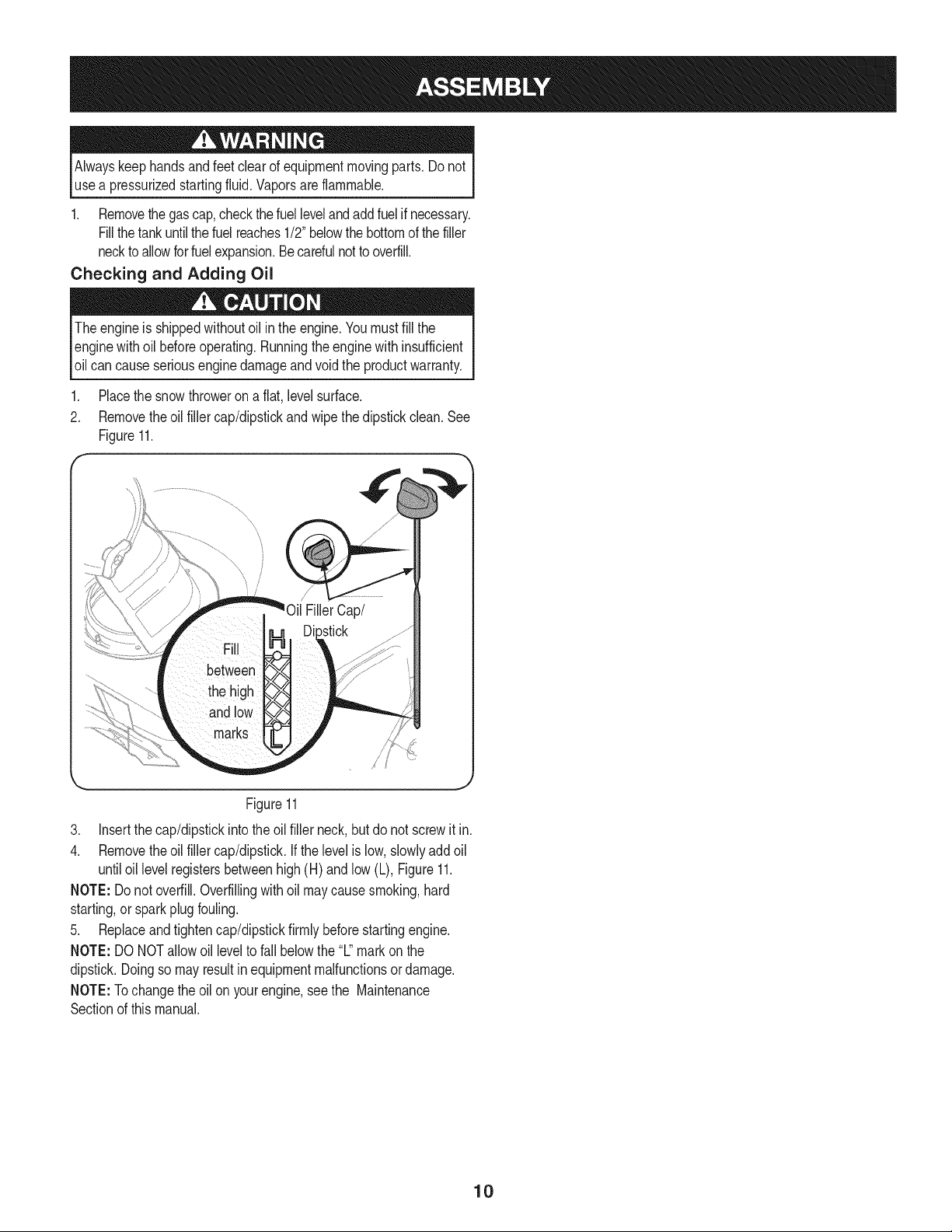
Placethe snowthroweron a flat, levelsurface.
2. Removetheoil fillercap/dipstickand wipethe dipstickclean. See
Figure11.
\
.
4.
Figure11
Insertthe cap/dipstickinto theoil filler neck,butdo not screwit in.
Removetheoil fillercap/dipstick.Ifthe levelis low,slowlyaddoil
untiloil levelregistersbetweenhigh(H) andlow(L), Figure11.
NOTE: Donot overfill.Overfillingwithoil maycausesmoking,hard
starting,or sparkplugfouling.
5. Replaceandtightencap/dipstickfirmlybeforestartingengine.
NOTE: DONOTallowoil levelto fall belowthe"L"mark on the
dipstick.Doingso mayresultin equipmentmalfunctionsor damage.
NOTE:Tochangethe oilon yourengine,see the Maintenance
Sectionof thismanual.
10
f Auger
ChuteAssembl'
Shave
RecoilStarterHandle
ChuteRotation
Gas Cap
Aug
Figure
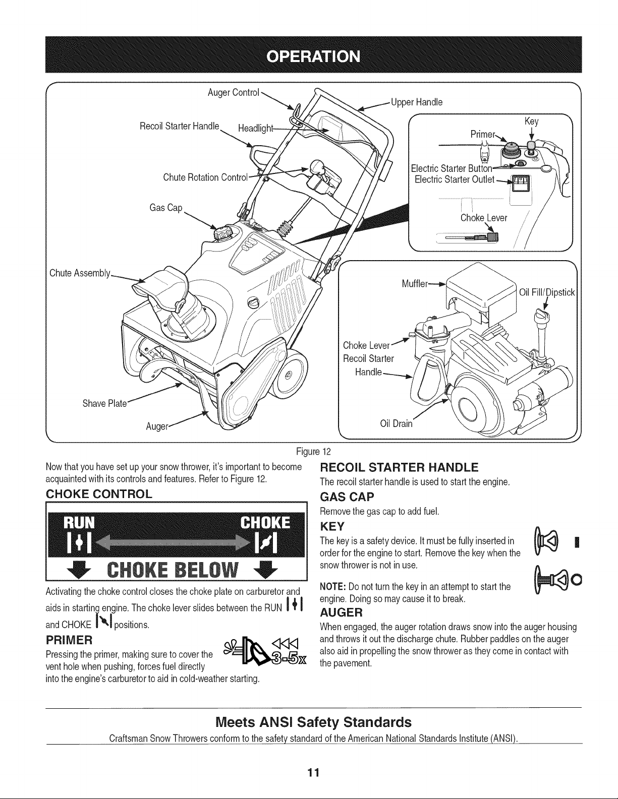
Nowthatyou havesetupyour snowthrower,it's importantto become
acquaintedwith itscontrolsandfeatures.Referto Figure12.
CHOKE CONTROL
CHO BELOW
Activatingthechokecontrolclosesthechoke plateon carburetorand
aidsin startin_,,.lengine.Thechokeleverslidesbetweenthe RUN I + !
andCHOKE i",1 positions.
PRIMER __%_
Pressingthe primer,makingsureto coverthe
ventholewhen pushing,forcesfueldirectly
intothe engine'scarburetorto aidin cold-weatherstarting.
Key
ElectricStarter Button
ElectricStarterOutlet
Oil Drain
12
RECOIL STARTER HANDLE
The recoilstarterhandleis usedto startthe engine.
GAS CAP
Removethe gascap to addfuel.
KEY
The keyis a safetydevice.Itmust befullyinsertedin
orderfor theengineto start.Removethe keywhenthe
snowthroweris not inuse.
NOTE:Do notturn the keyinan attemptto startthe
engine.Doingso maycauseit to break.
AUGER
Whenengaged,the augerrotationdrawssnow intothe augerhousing
andthrowsit out the dischargechute.Rubberpaddleson theauger
also aidin propellingthe snowthroweras theycomein contactwith
the pavement.
Meets ANSI Safety Standards
CraftsmanSnowThrowersconformto the safetystandardof the AmericanNationalStandardsInstitute(ANSI).
11
AUGER CONTROL
Locatedon the upperhandle,the augercontrol handleis usedto
engageanddisengagedriveto the auger.Squeezethe controlhandle
againstthe upperhandleto engagethe auger;releaseit to disengage.
MUFFLER
Engineexhaustexitsthe enginevia the muffler.
CHUTE ROTATION CONTROL
Thechuterotatecontrolis locatedin the centerof the controlpanel
andcontrolsthe directionsnowis thrown.Depressthe buttonand
rotatethe chuterotationcontrolto the rightto turnthe chuteto the right
androtateto the leftto turn the chuteto the left.
CHUTE ASSEMBLY
The pitchof the dischargechutecontrolsthe angleat whichthe snow
is thrown.Loosenthe wing knobonthe side of the dischargechute
beforepivotingthe dischargechute upwardor downward.Retighten
the knoboncethe desiredpositionhas beenachieved.
SHAVE PLATE
The shaveplatemaintainscontactwith the pavementas the snow
throweris propelled,allowingsnow closeto thepavement'ssurfaceto
bedischarged.
OIL FILL/DIPSTICK
Engineoillevelcan becheckedand oil addedthroughtheoil fill.
OIL DRAIN
Engineoilcan bedrainedthroughtheoil drain.
HEADLIGHT
The headlightis locatedon the uppercenterof the controlpanelandis
onwhenthe snowthroweris running.
ELECTRIC STARTER OUTLET
Requiresthe useof a three-prongoutdoorextensioncordand a 120V
powersource/walloutlet.
ELECTRIC STARTER BUTTON
Pressingthe electricstarterbuttonengagesthe engine'selectric
starterwhenpluggedintoa 120Vpowersource.
BEFORE STARTING THE ENGINE
machineand inthis manualbefore
STARTING THE ENGINE
3ressurizedstartinc areflammable.
Toavoidcarbonmonoxidepoisoning,makesure theengineis
outdoorsin awell-ventilatedarea.
1. Makecertainthe auger controlis in thedisengaged(released)
position.
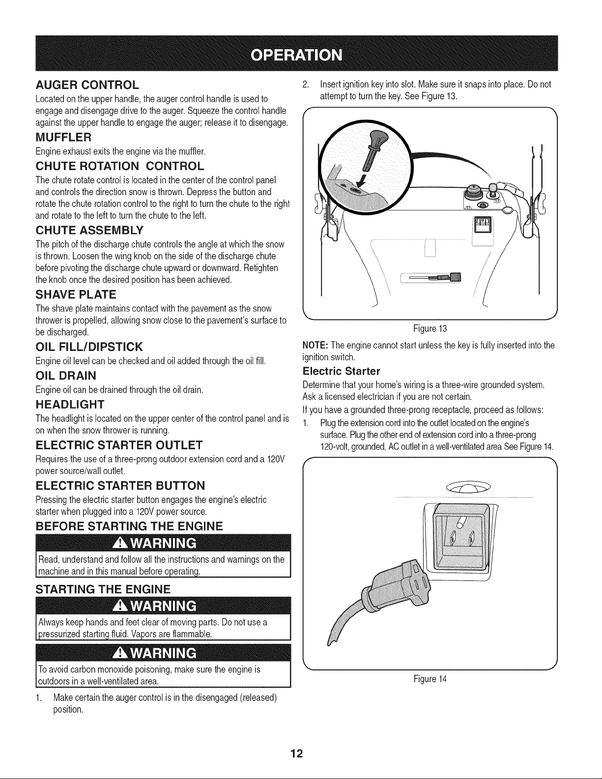
2. Insertignitionkeyinto slot.Makesure it snapsinto place.Do not
attemptto turn the key.See Figure13.
Figure13
NOTE: Theenginecannotstartunlessthe keyis fullyinsertedintothe
ignitionswitch.
Electric Starter
Determinethatyourhome'swiringis a three-wiregroundedsystem.
Aska licensedelectricianif you arenotcertain.
Ifyou havea groundedthree-prongreceptacle,proceedas follows:
1. Plugtheextensioncordintotheoutletlocatedon theengine's
surface.Plugtheotherendofextensioncordintoa three-prong
120-volt,grounded,ACoutletin a well-ventilatedareaSeeFigure14.
f
Figure14
12
2. Pushthechoke leverto the CHOKEI'e,I position.
a
3. If theengine is warm,placethe choke in the RUNi ! position
insteadof CHOKEI_1.
4. Pushthe primerthree(3) times, makingsureto coverthe vent
holewhenpushing.
5. If theengine is warm,pushthe primerbuttononly once.
6. Pushstarterbuttonto start engine.
7. Oncethe enginestarts,releasestarterbutton.
8. Allowtheengine to warmup severalminutes,adjustingchoke
| |
towardRUN| _position.Waituntil enginerunssmoothlybefore
eachchokeadjustment.
9. Whendisconnectingthe extensioncord, alwaysunplugthe end
at the three-prongwalloutletbeforeunpluggingthe oppositeend
fromthe snowthrower.
Recoil Starter
1. Pushthechokeleverto the CHOKEI_1 position.
2. If theengine is warm,placethe choke in the RUNI_1 position
insteadof CHOKEI"_1.
3. Pushthe primerthree(3) times, makingsureto coverthe vent
holewhenpushing.
4. If theengine is warm,pushthe primerbuttononly once.
5. Graspthe recoilstarterhandleand slowlypull the ropeout. At
the pointwhereit becomesslightlyharderto pullthe rope,slowly
allowthe ropeto recoil.
6. Pull the starterhandlewith a firm, rapid stroke.Donot release
the handleandallowit to snap back.Keepa firmholdonthe
starterhandleandallowit to slowlyrecoil.
7. Allowtheengine to warmup severalminutes,adjustingchoke
| |
towardRUN| _position.Waituntil enginerunssmoothlybefore
eachchokeadjustment.
STOPPING THE ENGINE
1. Runthe enginefor a few minuteswithoutload beforestoppingto
helpdry off anymoistureon theengine.
2. To stopthe engine removethe keyand storeit in a safe place.
3. Wipeall the snowand moistureawayfrom the enginecontrols
area.
Muffler,engineandsurroundingareasbecomehotand can causea
burn. Becarefulanddo not touchwhenthey are hot.
ENGAGING THE AUGER
Engagethe augerby squeezingtheaugercontrolagainstthe upper
handle.Releasethe controlto stop the auger.
ENGAGING THE DRIVE
Liftup slightlyon the upper handleto allowthe rubberpaddleson the
augerto contactthe pavementandpropelthe snowthrowerforward.
Pushingdownwardonthe handlewill raisethe augeroff the ground
and stopthe forwardmotion.
NOTE:Excessiveupwardpressureonthe handlewill resultin
prematurewearto the rubberaugerpaddles,whichwill notbecovered
bythe warranty.
CLEARING A CLOGGED DISCHARGE CHUTE
Handcontactwith the rotatingimpellerinsidethe dischargechute
isthe mostcommoncauseof injuryassociatedwithsnowthrowers.
Neveruseyourhandto cleanoutthe dischargechute.
Toclear thechute:
1. SHUTTHE ENGINEOFF!
2. Wait 10secondsto be surethe impellerbladeshavestopped
rotating.
3. Alwaysusea clean-outtool or stick,notyour hands.
13
MAINTENANCE SCHEDULE
Beforeperforminganytype of maintenance/service,disengageall
controlsand stopthe engine.Wait untilall movingparts havecome
to a completestop.Disconnectsparkplug wireand groundit against
the engineto preventunintendedstarting.Alwayswearsafetyglasses
duringoperationor whileperforminganyadjustmentsor repairs.
Followthe maintenanceschedulegiven below.Thischartdescribes
serviceguidelinesonly. Usethe ServiceLog columnto keeptrackof
completedmaintenancetasks.To locate the nearest Sears Service
Centeror to scheduleservice,simplycontactSearsat
1-800-4-MY-HOME®.
Eachuse .
2.
= =
1. Check
2. Clean
Engineoillevel.
Snowthrowerandexhaust
area.
Engineoil.
Engineoil.
Exhaustarea.
Sparkplug.
Engineoil
Sparkplug
Pivotpoints
Controlhandle
Extensionspring
1st5 hours 1. 1. Change.
Every5hours 1. 1. Check.
2. 2. Clean.
25 hours 1. 2. Check.
Everyseason/50hours 1. 1. Change
Everyseason/100hours 1. 1. Clean,replace,re-gap
Everyseason/Before 1. 1. Lubricate
storage 2. 2. Lubricate
3. 3. Lubricate
ENGINE MAINTENANCE
usedoil.
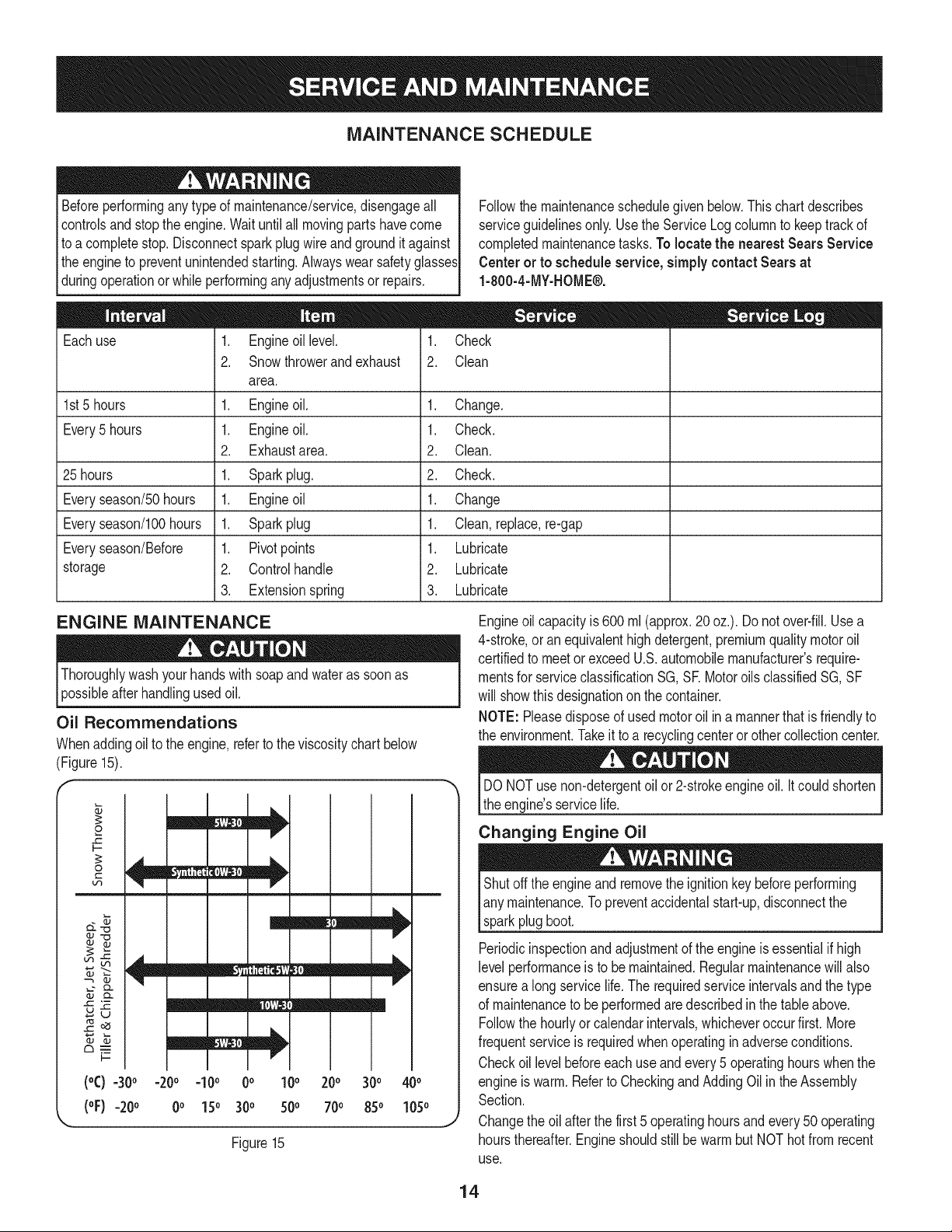
Oil Recommendations
Whenaddingoilto the engine,referto theviscositychartbelow
(Figure15).
£
F-
O
Lf_
CL
oJ t'_
I-=
I
- r I ] [
mW/==b,
Iv
V
mm /m!
mm mlb,
(°C) =30° -20o =10o 0o 100 200 300 400
(oF)-20 o 0o 150 300 500 700 850 1050
Figure15
Engineoil capacityis 600ml (approx.20oz.). Do notover-fill.Usea
4-stroke,oran equivalenthighdetergent,premiumquality motoroil
certifiedto meetor exceedU.S.automobilemanufacturer'srequire-
mentsfor serviceclassificationSG, SE Motoroils classifiedSG, SF
will showthis designationon the container.
NOTE: Pleasedisposeof used motoroilin a mannerthatisfriendlyto
the environment.Takeit to a recyclingcenteror othercollectioncenter.
DONOTusenon-detergentoil or2-strokeengineoil. It couldshorten
the engine'sservicelife.
Changing Engine Oil
Shutoffthe engineand removethe ignitionkey beforeperforming
any maintenance.Topreventaccidentalstart-up,disconnectthe
sparkplugboot.
Periodicinspectionandadjustmentof the engineisessentialif high
level performanceis to bemaintained.Regularmaintenancewill also
ensurea longservicelife.The requiredserviceintervalsandthe type
of maintenanceto be performedaredescribedinthe tableabove.
Followthe hourlyorcalendarintervals,whicheveroccur first. More
frequentserviceis requiredwhenoperatingin adverseconditions.
Checkoil levelbeforeeachuse andevery5 operatinghourswhenthe
engineiswarm.Referto CheckingandAdding Oil in theAssembly
Section.
Changethe oil afterthe first5 operatinghoursandevery50 operating
hoursthereafter.Engineshouldstillbe warm butNOT hotfrom recent
use.
14
.
2.
f
Drainfuelfromthe tankby runningtheengineuntilthe fueltankis
empty.Besurethe fuel fill capis secure.
Removethethreescrewsthatsecurethelowerpanel.Removethe
lowerpanelby liftingupon the panelto freethetabsatthe bottom
d thepanelfromthetab slotsandthenpullback.See Figure16.
/
k. j
Figure16
NOTE:The bottomof the panelhastabsthathelpholdit in place.
NOTE:An oildrainextensionkit is availableseparately.Contacta
SearsPartsand RepairCenterfor kit #753-06684.
3. Placea suitableoil collectioncontainerunderthe oil drain plug.
4. Removetheoil drain plug,Figure17.
F 1
k_ Oil DrainPlug
Figure17
7. Refillwith the recommendedoil and checktheoil level; referto
CheckingandAddingOil in the AssemblySection.
8. Reinstallthe oil fillercap/dipsticksecurely.
9. Re-installthe lowerpanel byplacingthetabs in the tab slots,
liftingthe panelintoplaceandsecurewith the threescrews
removedinstep 2.
Spark Plug
DONOTcheck fora sparkwiththe sparkplugremoved.DONOT
cranktheenginewith the sparkplug removed.
Ifthe enginehas beenrunning,the mufflerwill be very hot. Becareful
not to touchthemuffler.
The sparkplugshouldbecheckedevery 25 hoursand changedonce
a seasonor every100hours.Toensureproperengineoperation,the
sparkplugmustalso beproperlygappedand freeof deposits.
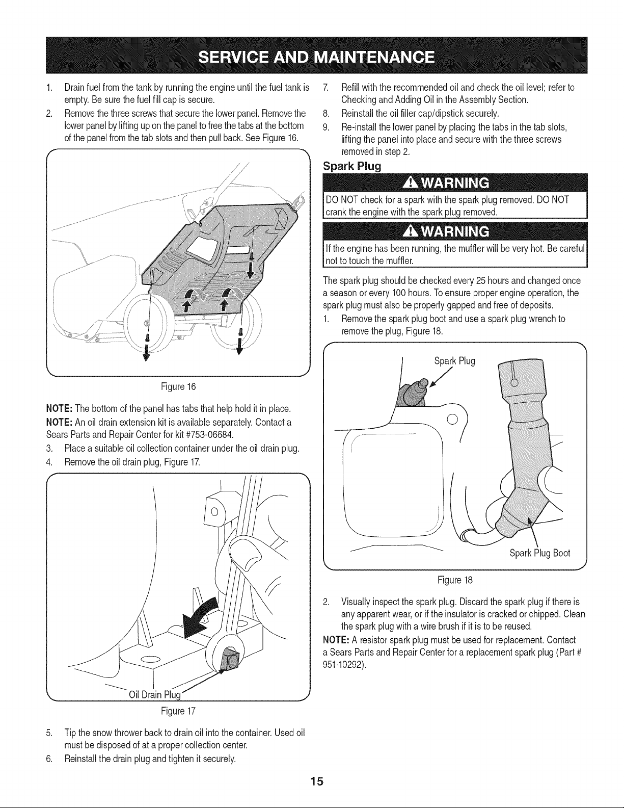
1. Removethe sparkplug bootand usea spark plugwrenchto
removethe plug,Figure18.
SparkPlugBoot
Figure18
2. Visuallyinspectthe sparkplug. Discardthe sparkplug if thereis
any apparentwear,or if the insulatoris crackedorchipped.Clean
the sparkplugwitha wire brushif it is to be reused.
NOTE:A resistorsparkplugmust beusedfor replacement.Contact
a Sears PartsandRepairCenterfor a replacementsparkplug(Part#
951-10292).
5. Tip thesnow throwerbackto drain oil intothe container.Usedoil
mustbedisposedof at a propercollectioncenter.
6. Reinstallthe drain plugand tightenit securely.
15
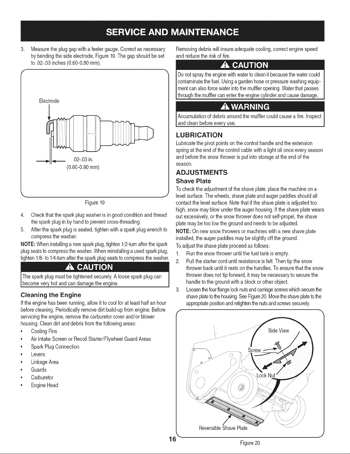
.
Measurethe pluggapwith a feelergauge.Correctas necessary
by bendingthe side electrode,Figure19.The gapshouldbeset
to .02-.03inches(0.60-0.80ram).
Electrode
.02-.03in.
(0.60-0.80ram)
Figure19
4. Checkthat thespark plug washeris in good conditionandthread
the sparkplugin by handto preventcross-threading.
5. Afterthe sparkplug is seated,tightenwith a sparkplugwrenchto
compressthe washer.
NOTE:Wheninstallinga newsparkplug,tighten1/2-turnafterthe spark
plugseatsto compressthe washer.Whenreinstallingausedsparkplug,
tighten1/8-to 1/4-turnafterthe sparkplugseatsto compressthe washer.
Thesparkplugmustbetightenedsecurely.A loosesparkplug can
becomeveryhotand can damagethe engine.
Cleaning the Engine
Ifthe enginehasbeenrunning,allowit to cool for at leasthalfan hour
beforecleaning.Periodicallyremovedirt build-upfromengine.Before
servicingthe engine,removethecarburetorcover and/orblower
housing.Cleandirt and debrisfrom thefollowingareas:
• CoolingFins
• AirIntakeScreenor RecoilStarter/FlywheelGuardAreas
• SparkPlugConnection
• Levers
• LinkageArea
• Guards
• Carburetor
• EngineHead
Removingdebriswillinsureadequatecooling,correctengine speed
and reducethe risk of fire.
Donotspraytheenginewithwatertocleanit becausethewatercould
contaminatethe fuel.Usingagardenhoseor pressurewashingequip-
mentcan alsoforcewaterintothe muffleropening.Waterthatpasses
throughthemufflercanentertheenginecylinderandcausedamage.
Accumulationof debrisaroundthe mufflercouldcausea fire.Inspect
andclean beforeevery_use.
LUBRICATION
Lubricatethe pivotpointson thecontrolhandleand the extension
springat the endof the controlcablewitha light oilonceeveryseason
and beforethe snowthroweris put intostorageat the endof the
season.
ADJUSTMENTS
Shave Plate
Tocheckthe adjustmentof the shaveplate,placethe machineon a
level surface.Thewheels,shaveplateandaugerpaddlesshouldall
contactthe levelsurface.Notethat if the shaveplateis adjustedtoo
high, snowmayblowunderthe augerhousing.If the shaveplatewears
out excessively,or the snowthrowerdoesnot self-propel,the shave
plate maybetoo low the groundand needsto beadjusted.
NOTE: Onnewsnowthrowersor machineswitha newshaveplate
installed,the augerpaddlesmay be slightlyoff the ground.
Toadjustthe shaveplateproceedas follows:
1. Runthe snowthroweruntilthe fueltank is empty.
2. Pullthe startercorduntil resistanceis felt.Then tip the snow
throwerbackuntilit restsonthe handles.To ensurethat the snow
throwerdoesnot tip forward,it maybe necessaryto securethe
handleto the groundwitha blockor other object.
3. Loosenthefourflangelocknutsandcarriagescrewswhichsecurethe
shaveplatetothehousing.SeeFigure20.Movetheshaveplatetothe
appropriatepositionandretightenthenutsandscrewssecurely.
ReversibleShavePlate
J
16 ``.¸
Figure20
4. Tipthesnowthrowerbacktotheoperatingpositionandpullthe
starterhandleafewtimestoseeifitisdifficulttopull.
5. Ifthestarterisdifficulttopull,removethesparkplugandpullthe
handleseveraltimestoensurethatanyoiltrappedintheengine
headisremoved.
Oilmaycomeoutofthesparkplugholewhenitisremovedandthe
starterhandleispulled.
6. Inspectthesparkplug.Ifitiswet,cleanoffanyoilbefore
re-installing.
Control Cable
Asaresultofboththecontrolcableandtheaugerdrivebeltstretching
duetowear,periodicadjustmentsmaybenecessary.Iftheauger
seemstohesitatewhenrotating,proceedasfollows:
Theupperholeinthecontrolhandleprovidesforanadjustmentin
cabletension.Toadjust,disconnecttheendofcontrolcablefromthe
bottomholeinthecontrolhandleandreinsertitintheupperhole.
InsertthecablefromtheoutsideasshowninFigure21.
f
Control
Cable
/
j
/
/
/
Figure21
Testthe snowthrowerto seeif there is a noticeabledifference.If
aftertheadjustmentto the controlcablethe augerstill hesitateswhen
rotating,see BeltReplacementfor instructionson replacingthebelt.
Chute Assembly
Referto the Assemblysectionfor instructionsonadjustingthechute
assembly.
AUGER DRIVE BELT REPLACEMENT
1. Runthe snowthroweruntilthe fueltank is empty.
2. Pullthe recoilstarterhandleuntil resistanceis felt.Thentip the
snowthrowerbackuntil it restson thehandles.
3. Slidea boardup throughthe augerandthroughthe chuteto
securethe augerin place.
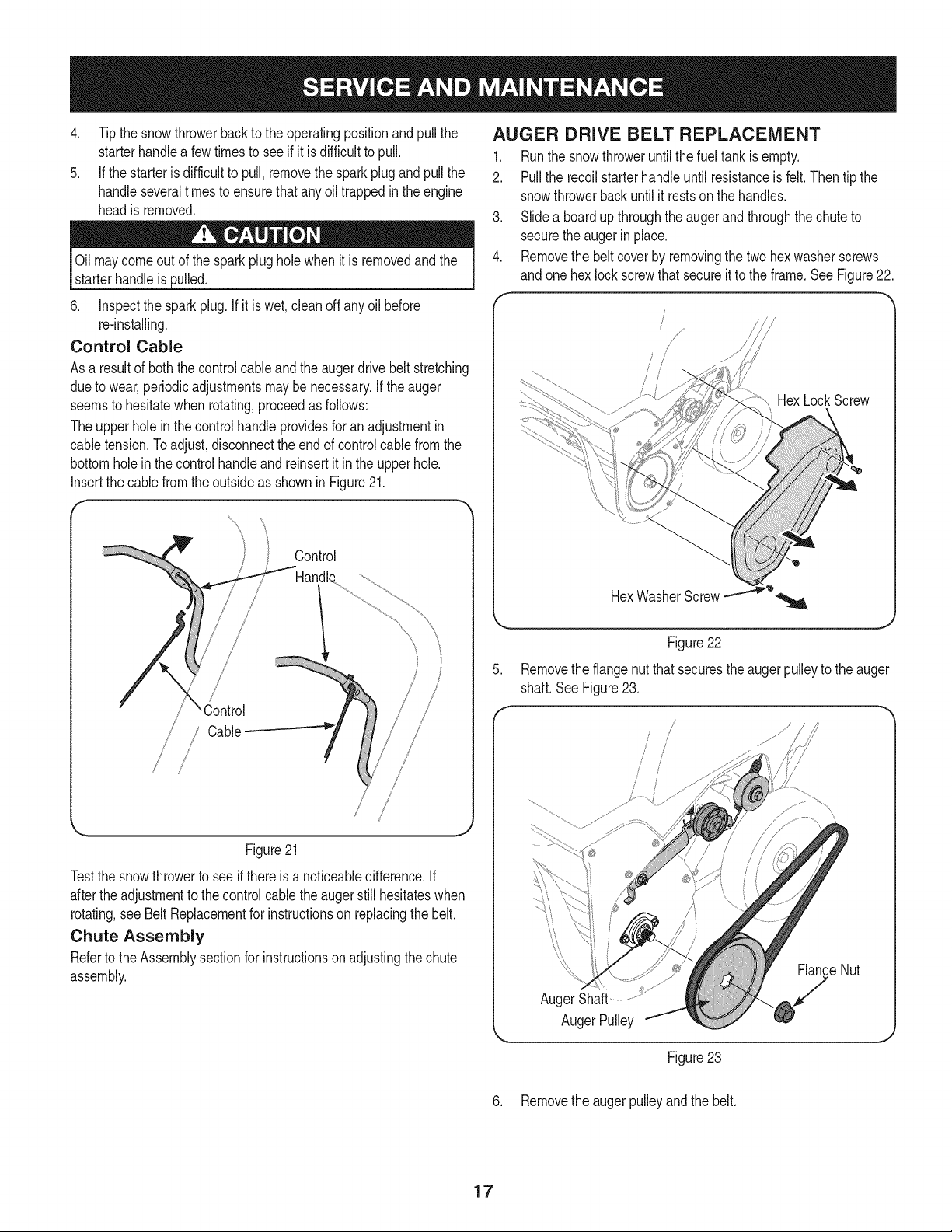
4. Removethe beltcover by removingthe two hexwasherscrews
andone hexlock screwthat secureit to the frame.SeeFigure22.
HexLockScrew
.
Figure22
Removethe flangenutthat securestheauger pulleyto the auger
shaft.SeeFigure23.
/
AugerShaft
AugerPulley
FlangeNut
J
J
Figure23
6. Removethe augerpulleyandthe belt.
17
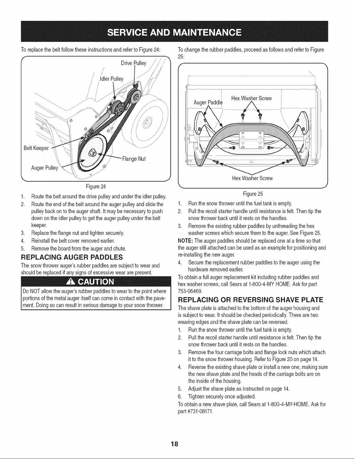
To replacethe belt followtheseinstructionsandreferto Figure24:
Drive
js
Figure24
1. Routethe beltaroundthe drivepulleyand underthe idler pulley.
2. Routethe end of the beltaroundthe auger pulleyand slidethe
pulleybackon to the augershaft.It maybe necessaryto push
downonthe idlerpulleyto get theaugerpulleyunderthe belt
keeper.
3. Replacethe flangenut and tightensecurely.
4. Reinstallthe beltcover removedearlier.
5. Removethe boardfromthe auger and chute.
REPLACING AUGER PADDLES
The snowthrowerauger'srubberpaddlesare subjectto wearand
shouldbereplacedif any signsof excessiveweararepresent.
Do NOTallowthe auger'srubberpaddlesto wearto the pointwhere
Iportionsof the metalaugeritselfcancomein contactwiththe pave-
_ment.Doingsocan resultin seriousdamageto yoursnowthrower.
Tochangethe rubberpaddles,proceedas followsand referto Figure
25:
HexWasherScrew
HexWasherScrew
Figure25
1. Runthe snowthroweruntilthe fueltank is empty.
2. Pullthe recoilstarterhandleuntil resistanceis felt.Then tip the
snowthrowerbackuntil it restson the handles.
3. Removethe existingrubberpaddlesby unthreadingthe hex
washerscrewswhichsecurethem to the auger.See Figure25.
NOTE: Theaugerpaddlesshouldbe replacedone at a time so that
the augerstillattachedcan be usedas anexamplefor positioningand
re-installingthe newauger.
4. Securethe replacementrubberpaddlesto the augerusingthe
hardwareremovedearlier.
Toobtaina full augerreplacementkit includingrubberpaddlesand
hex washerscrews,callSearsat 1-800-4-MYHOME.Askfor part
753-06469.
REPLACING OR REVERSING SHAVE PLATE
The shaveplateis attachedto the bottomof the augerhousingand
is subjectto wear.Itshouldbe checkedperiodically.Thereare two
wearingedgesand the shaveplatecan be reversed.
1. Runthe snowthroweruntilthe fueltank is empty.
2. Pullthe recoilstarterhandleuntil resistanceis felt.Then tip the
snowthrowerbackuntil it restson the handles.
3. Removethe fourcarriageboltsandflangelocknutswhichattach
it to the snowthrowerhousing.Referto Figure20 on page 14.
4. Reversethe existingshaveplateor installa newone, makingsure
the new shaveplateandthe headsof the carriagebolts are on
the insideof the housing.
5. Adjustthe shaveplateas instructedon page 14.
6. Tightensecurelyonceadjusted.
Toobtaina new shaveplate,call Searsat 1-800-4-MY-HOME.Askfor
part #731-08171.
18
Ifthe snowthrowerwillnot be usedfor30 daysor longer,or if it is the endof the snowseasonwhenthe lastpossibilityof snowis gone,the
equipmentneedsto bestoredproperly.Followstorageinstructionsbelowto ensuretop performancefrom the snowthrowerfor manymoreyears.
PREPARING THE ENGINE
Enginesstoredover30 days need to be drainedof fuel to prevent
deteriorationandgumfromforminginthe fuel systemor onessential
carburetorparts.If thegasolineinyourenginedeterioratesduring
storage,youmay needto havethe carburetor,and otherfuel system
components,servicedor replaced.
1. Removeall fuel fromthe tank by runningtheengine untilit stops.
2. Changethe engineoil.
3. Removethe sparkplug and pourapproximately1oz.(30 ml)of
cleanengineoil intothe cylinder.Pullthe recoilstarterseveral
timesto distributethe oil,and reinstallthe sparkplug.
4. Cleantheexteriorof the engineby wipingdirt anddebrisfromthe
followingareas:
• CoolingFins
• AirIntakeScreenor RecoilStarter/FlywheelGuardAreas
• SparkPlugConnection
• Levers
LinkageArea
Guards
Carburetor
EngineHead
!
Do notspraythe enginewithwaterto cleanit becausethe watercould
contaminatethefuel. Usinga gardenhoseorpressurewashingequip-
Imentcanalsoforcewaterintothemuffleropening.Waterthatpasses
[throughthe mufflercan entertheenginecylinderandcausedamage.
5. Storein a clean,dry and wellventilatedarea awayfromany
appliancethat operateswith a flameor pilot light,such as a
furnace,waterheateror clothesdryer.Avoidany areawith a spark
producingelectricmotor,or wherepowertools are operated.
Neverstoresnowthrowerwith fuel in tank indoorsor in poorlyventi-
latedareas,wherefuel fumesmayreachan openflame,spark or pilol
lightas ona furnace,water heater,clothesdryer or gas appliance.
6. If possible,avoidstorageareaswith high humidity.
7. Keepthe enginelevelin storage.Tiltingthe engine can cause
fuelor oil leakage.
PREPARING SNOW THROWER
Ifthe snowthrowerwill not beusedfor 30daysor longer,followthe
instructionsbelow.
1. Storethe equipmentin a clean, dry area.
2. Wipedownthe snow throwerwith a rag and removeanydirt or
debris.
3. Ifstoringthe snowthrowerin anunventilatedarea,rustproofthe
metalparts of the machinewitha lightoil or siliconecoating.
19
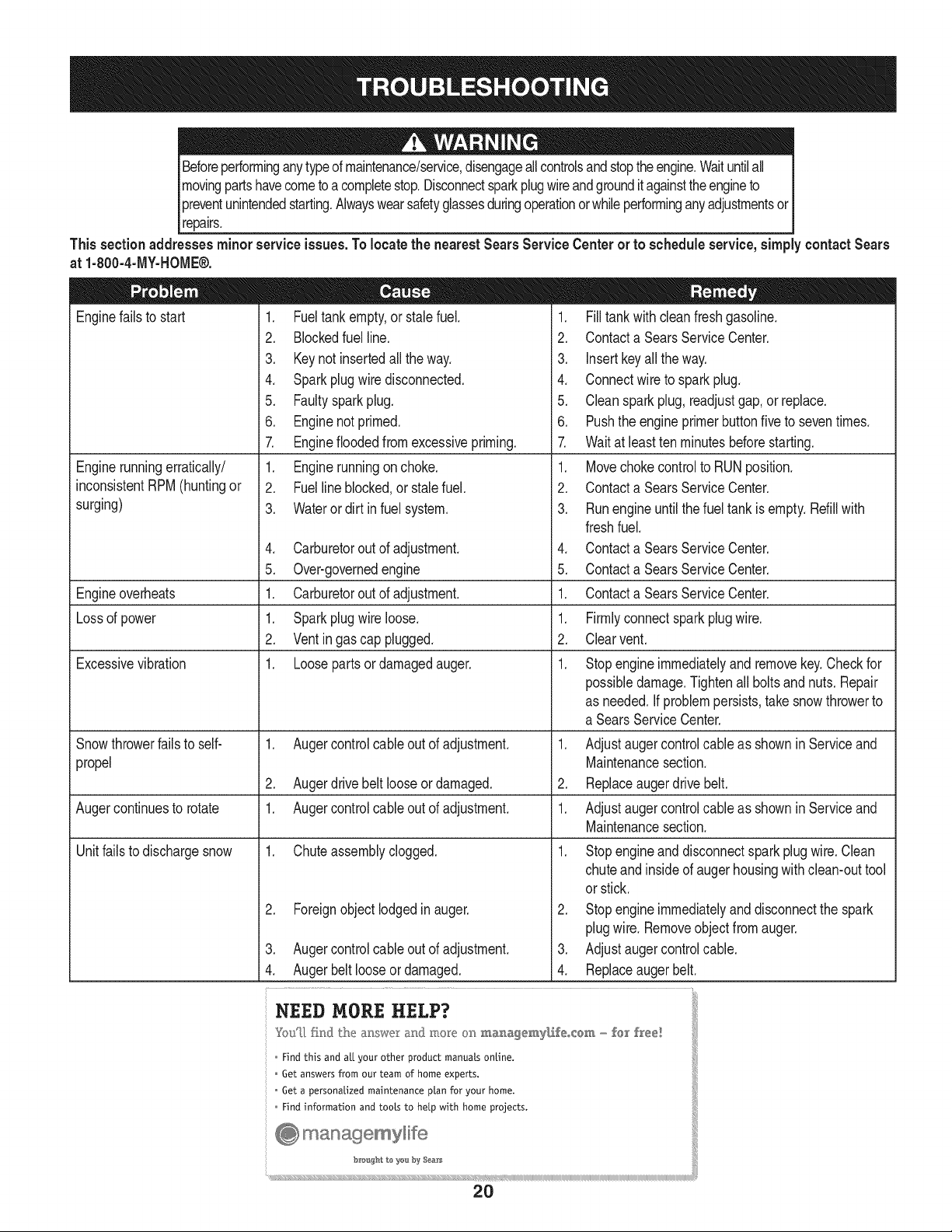
Beforeperforminganytypeof maintenance/service,disengageall controlsandstopthe engine.Waituntilall
movingpartshavecometo acompletestop.Disconnectsparkplugwireandgrounditagainstthe engineto
Ipreventunintendedstarting.Alwayswearsafetyglassesduringoperationorwhileperforminganyadjustmentsor
[repairs.
This section addresses minor service issues. To locate the nearest Sears Service Center or to schedule service, simply contact Sears
at 1-800-4-MY-HOME®.
Enginefailsto start 1. Fueltank empty,or stalefuel.
2. Blockedfuel line.
3. Keynot insertedallthe way.
4. Sparkplug wiredisconnected.
5. Faultysparkplug.
6. Enginenot primed.
1. Filltank with cleanfreshgasoline.
2. Contacta SearsServiceCenter.
3. Insertkeyallthe way.
4. Connectwireto sparkplug.
5. Cleanspark plug,readjustgap,or replace.
6. Pushthe engineprimerbuttonfiveto seventimes.
Enginerunningerratically/
inconsistentRPM(huntingor
surging)
7. Enginefloodedfromexcessivepriming.
1. Enginerunningon choke.
2. Fuelline blocked,or stalefuel.
3. Wateror dirt in fuel system.
4. Carburetoroutof adjustment.
5. Over-governedengine
1. Carburetoroutof adjustment.
1. Sparkplugwireloose.
2. Ventin gascap plugged.
1. Looseparts or damagedauger.
7. Wait at leastten minutesbeforestarting.
1. Movechoke controlto RUNposition.
2. Contacta SearsServiceCenter.
3. Runengineuntilthefuel tank isempty.Rdill with
freshfuel.
4. Contacta SearsServiceCenter.
5. Contacta SearsServiceCenter.
1.
1.
2.
1.
Engineoverheats Contacta SearsServiceCenter.
Lossof power Firmlyconnectspark plugwire.
Clearvent.
Excessivevibration Stopengineimmediatelyandremovekey.Checkfor
possibledamage.Tightenall boltsand nuts.Repair
as needed.Ifproblempersists,take snowthrowerto
a SearsServiceCenter.
Snowthrowerfails to self- 1. Augercontrol cableoutof adjustment. 1. Adjustaugercontrolcableas shownin Serviceand
propel Maintenancesection.
2. Augerdrive beltlooseor damaged. 2. Replaceaugerdrivebelt.
Augercontinuesto rotate 1. Augercontrolcableoutof adjustment. 1. Adjustaugercontrolcableas shownin Serviceand
Maintenancesection.
Unitfailsto dischargesnow 1. Chuteassemblyclogged. 1.
2. Foreignobjectlodgedin auger.
3. Augercontrol cableoutof adjustment.
4. Auger beltlooseor damaged.
Stopengineanddisconnectsparkplug wire.Clean
chuteand insideof augerhousingwith clean-outtool
or stick.
2. Stopengine immediatelyand disconnectthe spark
plugwire. Removeobjectfrom auger.
3. Adjustauger controlcable.
4. Replaceaugerbelt.
lqg_/1 find the a_swez a[_d z[_or{÷on maztagemy[£e,,,_om - [0[ [ree!
Find this and all your other product manual.s onl.ine.
Get answers from our team of home experts.
Get a personaLized maintenance pl.an for your home.
Find information and tools to hel.p with home projects.
_ managemylife
b_g_t t_ ye_ By S_a_'s
2O

This page intentionally left blank. Use this page to make any notes regarding your snow thrower.
21
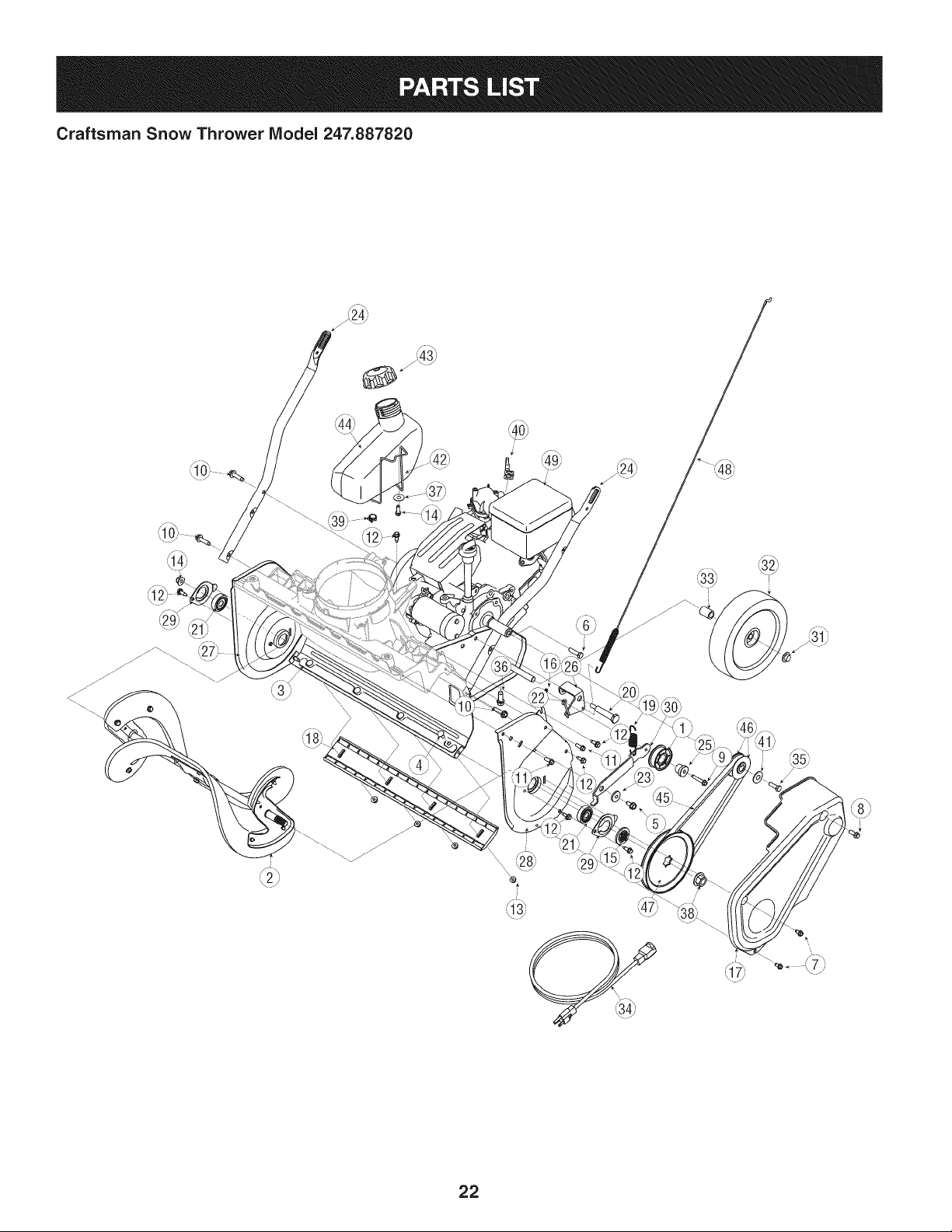
Craftsman Snow Thrower IViodel 247.887820
22
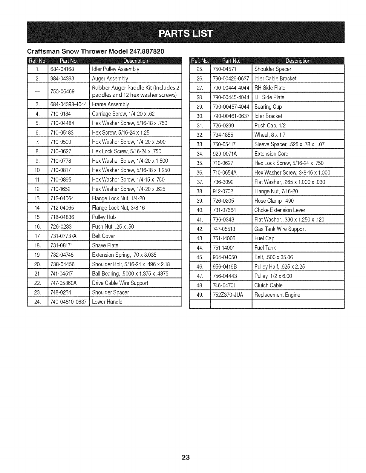
Craftsman Snow Thrower IViodel 247.887820
|= 0 =
684-04168 IdlerPulleyAssembly
2. 984-04393 AugerAssembly
Rubber Auger Paddle Kit (Includes 2
-- 753-06469
paddles and 12 hex washer screws)
3. 684-04398-4044
4. 710-0134
5. 710-04484
6. 710-05183
710-0599
FrameAssembly
CarriageScrew,1/4-20x .62
HexWasherScrew,5/16-18x .750
HexScrew,5/16-24x 1.25
HexWasherScrew,1/4-20x .500
8. 710-0627 HexLockScrew,5/16-24x .750
9. 710-0778 HexWasherScrew,1/4-20x 1.500
10. 710-0817 HexWasherScrew,5/16-18x 1.250
L
11. 710-0895
12. 710-1652
13. 712-04064
14. 712-04065
HexWasherScrew,1/4-15x .750
HexWasherScrew,1/4-20x .625
FlangeLockNut, 1/4-20
FlangeLockNut,3/8-16
15. L71804836 LPulleyHub
16. 726-0233 PushNut,.25 x .50
17. 731-07737A BeltCover
18. 731-08171 ShavePlate
19. 732-04748
20. 738-04456
21. 741-04517
22. 747-05360A
23. 748-0234
24. 749-04810-0637
ExtensionSpring,.70x 3.035
ShoulderBolt,5/16-24x .496x 2.18
BallBearing,.5000x 1.375x .4375
DriveCableWireSupport
ShoulderSpacer
LowerHandle
D = O 0
750-04571 ShoulderSpacer
26. 790-00426-0637 IdlerCable Bracket
27. 790-00444-4044 RHSide Plate
28. 790-00445-4044 LHSide Plate
29. 790-00457-4044 BearingCup
30. 790-00461-0637 IdlerBracket
31. 726-0299 PushCap, 1/2
32. 734-1855 Wheel,8 x 1.7
33. 750-05417 SleeveSpacer,.525x .78x 1.07
34. 929-0071A ExtensionCord
35. 710-0627 HexLockScrew,5/16-24x .750
36. 710-0654A HexWasherScrew,3/8-16x 1.000
37. 736-3092 FiatWasher,.265x 1.000x .030
38. 912-0702 FlangeNut,7/16-20
39. 726-0205 HoseClamp,.490
40. 731-07664 ChokeExtensionLever
41. 736-0343 FiatWasher,.330x 1.250x .120
42. 747-05513 Gas TankWire Support
43. 751-14006 FuelCap
44. 751-14001 FuelTank
45. 954-04050 Belt,.500x 35.06
46. 956-0416B PulleyHalf,.625x 2.25
47. 756-04443 Pulley,1/2 x 6.00
48. 746-04701 ClutchCable
49. 752Z370-JUA ReplacementEngine
23
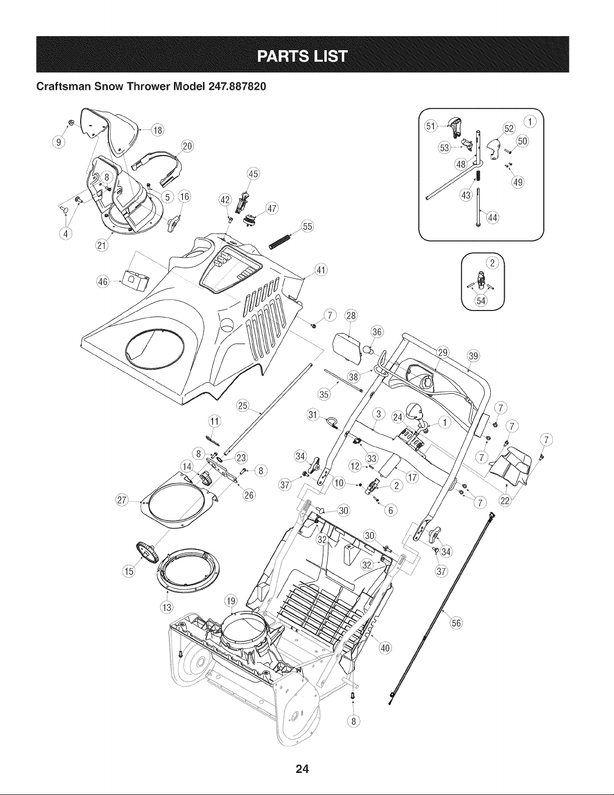
Craftsman Snow Thrower Model 247.887820
_55j
i
/
/
24
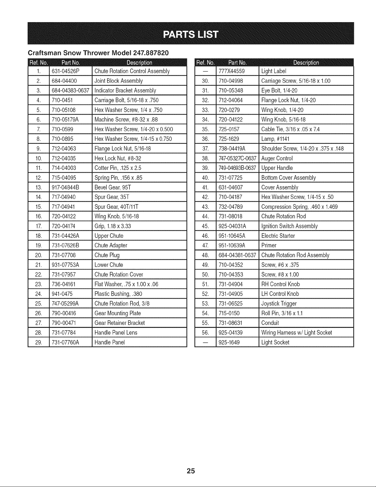
Craftsman Snow Thrower IViodel 247.887820
I_= 0 =
631-04526P ChuteRotationControlAssembly
2. 684-04400 JointBlockAssembly
3. _684-04383-0637 IndicatorBracketAssembly
4. 710-0451
5. 710-05108
6. 710-05179A
7. 710-0599
8. 710-0895
9. 712-04063
10. 712-04035
11. 714-04003
CarriageBolt,5/16-18x .750
HexWasherScrew,1/4x .750
MachineScrew,#8-32 x .88
HexWasherScrew,1/4-20x 0.500
HexWasherScrew,1/4-15x 0.750
FlangeLockNut,5/16-18
HexLockNut,#8-32
CotterPin,.125x 2.5
12. 715-04095 SpringPin, .156x .85
13. 917-04844B BevelGear,95T
14. 717-04940 SpurGear,35T
15. 717-04941 SpurGear,40T/11T
16. 720-04122 WingKnob,5/16-18
17. 720-04174 Grip,1.18x 3.33
18. 731-04426A UpperChute
19. ,731-07626B LChuteAdapter
20. 731-07708 ChutePlug
21. 931-07753A LowerChute
22. 731-07957 ChuteRotationCover
23. 736-04161 FiatWasher,.75x 1.00x .06
24. 941-0475 PlasticBushing,.380
25. 747-05299A ChuteRotationRod,3/8
26. 790-00416 GearMountingPlate
27. 790-00471 GearRetainerBracket
28. 731-07784 HandlePanelLens
29. 731-07760A HandlePanel
D = O
777X44559 LightLabel
30. 710-04998 CarriageScrew,5/16-18x 1.00
31. 710-05348 EyeBolt,1/4-20
32. 712-04064 FlangeLockNut, 1/4-20
33. 720-0279 Wing Knob,1/4-20
34. 720-04122 Wing Knob,5/16-18
35. 725-0157 CableTie,3/16x .05x 7.4
36. 725-1629 Lamp,#1141
37. 738-04419A ShoulderScrew,1/4-20x .375x .148
38. 747-05327C-0637AugerControl
39. 749-04693B-0637UpperHandle
40. 731-07725 BottomCoverAssembly
41. 631-04607 CoverAssembly
42. 710-04187 HexWasherScrew,1/4-15x .50
43. 732-04789 CompressionSpring,.460x 1.469
44. 731-08018 ChuteRotationRod
45. 925-04031A IgnitionSwitchAssembly
46. 951-10645A ElectricStarter
47. 951-10639A Primer
48. 684-04381-0637 Chute RotationRodAssembly
49. 710-04352 Screw,#6 x .375
50. 710-04353 Screw,#8 x 1.00
51. 731-04904 RHControlKnob
52. 731-04905 LHControlKnob
53. 731-06525 JoystickTrigger
54. 715-0150 RollPin,3/16x 1.1
55. 731-08631 Conduit
56. 925-04139 WiringHarnessw/Light Socket
-- 925-1649 LightSocket
25
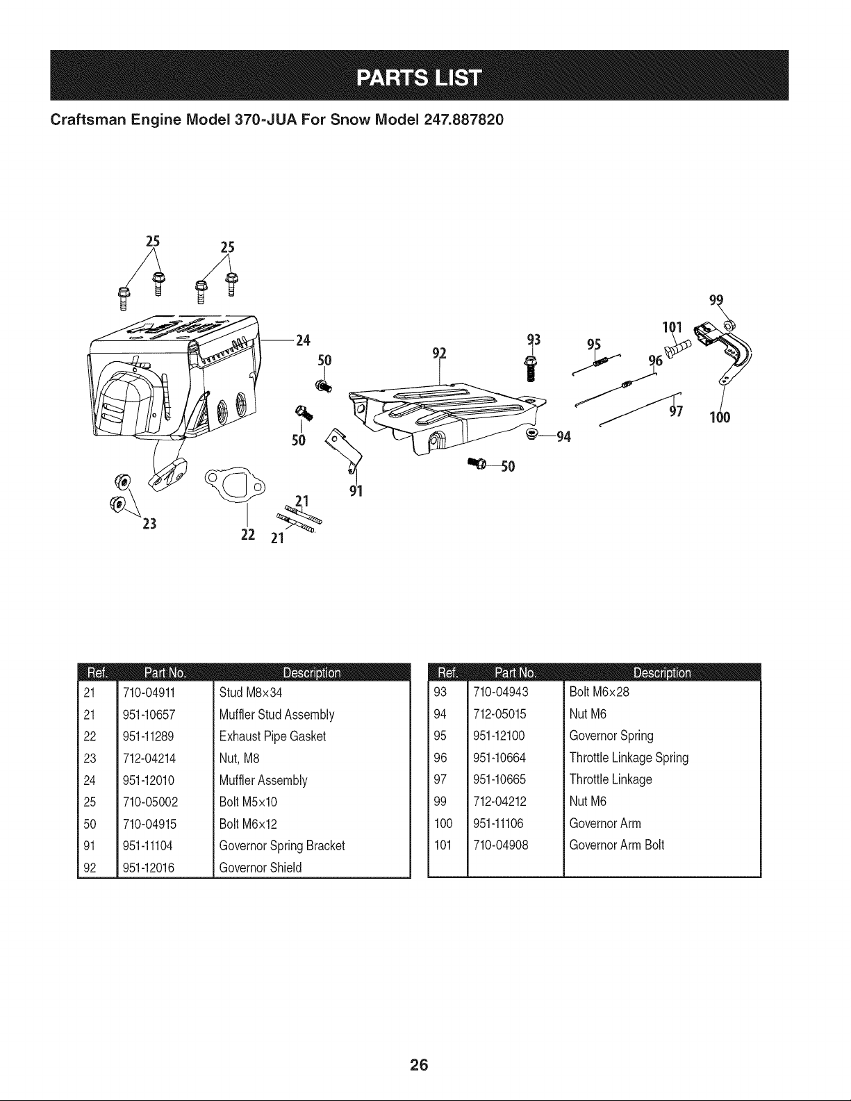
Craftsman Engine IViodel 370=JUA For Snow IViodel 247.887820
--24 _3
5O
22 21
m
21
21
22
23
24
25
5O
91
92
710-04911
951-10657
951-11289
712-04214
951-12010
710-05002
710-04915
951-11104
951-12016
D = O O
Stud M8x34
MufflerStudAssembly
ExhaustPipeGasket
Nut,M8
MufflerAssembly
BoltM5xl0
BoltM6x12
GovernorSpringBracket
GovernorShield
m
93
94
95
96
97
99
100
101
710-04943
712-05015
951-12100
951-10664
951-10665
712-04212
951-11106
710-04908
m = O O
BoltM6x28
NutM6
GovernorSpring
ThrottleLinkageSpring
ThrottleLinkage
NutM6
GovernorArm
GovernorArm Bolt
2G
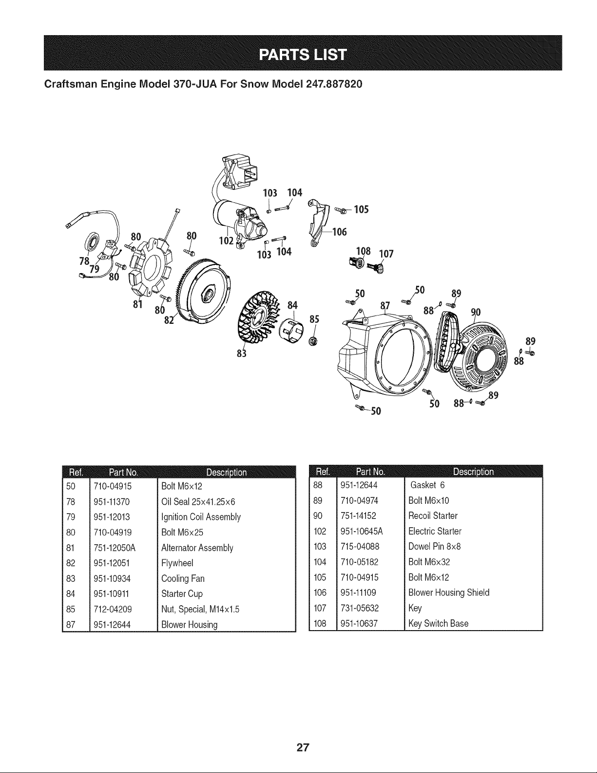
Craftsman Engine IViodel 370=JUA For Snow IViodel 247.887820
89
m
5O
78
79
8O
81
82
83
84
85
87
710-04915
951-11370
951-12013
710-04919
751-12050A
951-12051
951-10934
951-10911
712-04209
951-12644
D = W O
BoltM6x12
Oil Seal25x41.25x6
IgnitionCoil Assembly
BoltM6x25
AlternatorAssembly
Flywheel
CoolingFan
StarterCup
Nut,Special,M14x1.5
BlowerHousing
m
88
89
9O
102
103
104
105
106
107
108
951-12644
710-04974
751-14152
951-10645A
D = O O
Gasket 6
BoltM6xlO
RecoilStarter
ElectricStarter
715-04088
710-05182
710-04915
951-11109
731-05632
951-10637
DowelPin8x8
BoltM6x32
BoltM6x12
BlowerHousingShield
Key
KeySwitchBase
27
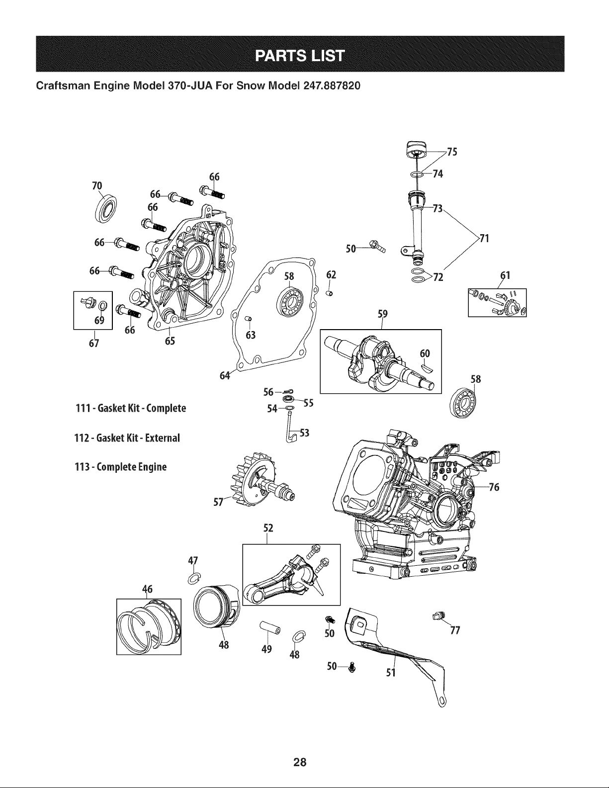
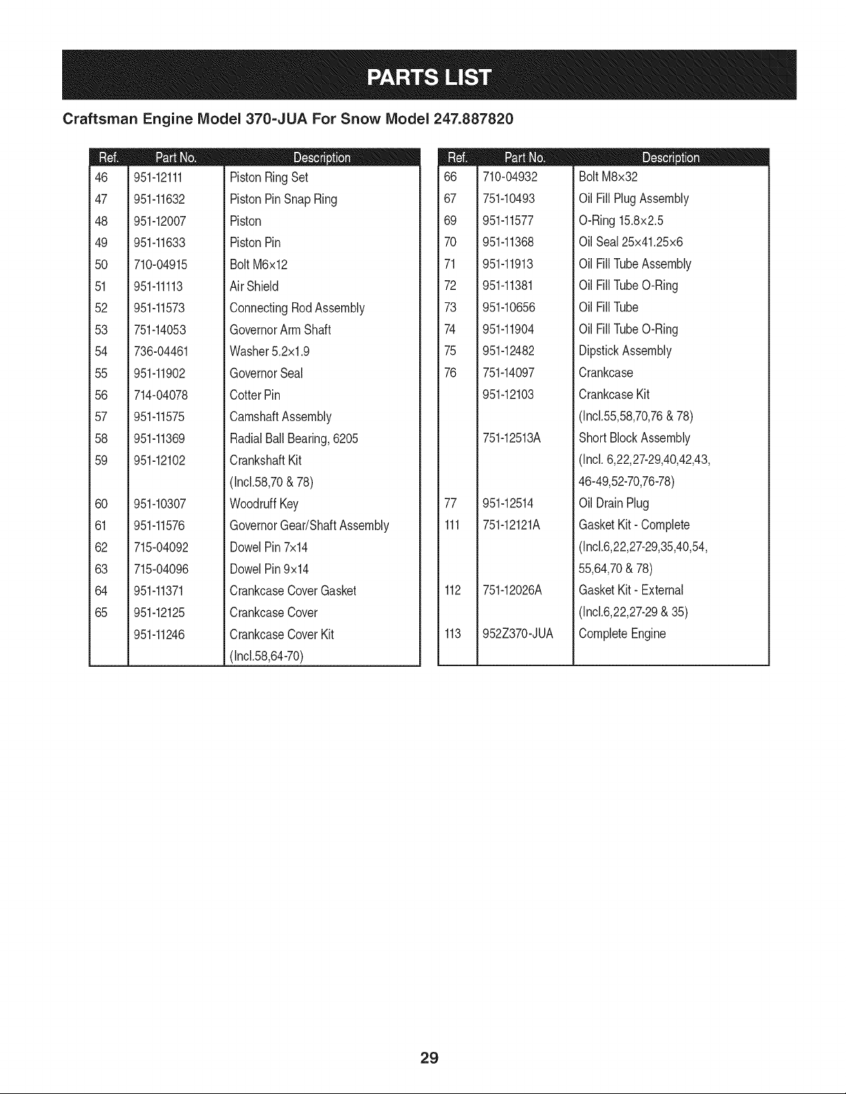
Craftsman Engine Model 370=JUA For Snow Model 247.887820
7O
I
67
65
111- GasketKit- Complete
112- Gasket Kit- External
113- Complete Engine
56 --_
_s
54--_
so--_
62 _72
9
48
52
I
49
28
Craftsman Engine IViodel 370=JUA For Snow IViodel 247.887820
m
46
47
48
49
5O
51
52
53
54
55
56
57
58
59
6O
61
62
63
64
65
951-12111
951-11632
951-12007
951-11633
710-04915
951-11113
951-11573
751-14053
736-04461
951-11902
714-04078
951-11575
951-11369
951-12102
951-10307
951-11576
715-04092
715-04096
951-11371
951-12125
951-11246
m = O O
PistonRingSet
PistonPinSnap Ring
Piston
PistonPin
Bolt M6x12
AirShield
ConnectingRodAssembly
GovernorArm Shaft
Washer5.2xl .9
GovernorSeal
CotterPin
CamshaftAssembly
RadialBallBearing,6205
CrankshaftKit
(Incl.58,70& 78)
WoodruffKey
GovernorGear/ShaftAssembly
DowelPin7x14
DowelPin9x14
CrankcaseCoverGasket
CrankcaseCover
CrankcaseCoverKit
(In01.58,64-70)
m
66
67
69
7O
71
72
73
74
75
76
77
111
112
113
710-04932
751-10493
951-11577
951-11368
951-11913
951-11381
951-10656
951-11904
951-12482
751-14097
951-12103
751-12513A
951-12514
751-12121A
751-12026A
952Z370-JUA
D = O O
BoltM8x32
OilFill PlugAssembly
O-Ring15.8x2.5
OilSeal25x41.25x6
OilFill TubeAssembly
OilFill TubeO-Ring
OilFill Tube
OilFill TubeO-Ring
DipstickAssembly
Crankcase
CrankcaseKit
(Incl.55,58,70,76& 78)
ShortBlockAssembly
(Incl.6,22,27-29,40,42,43,
46-49,52-70,76-78)
OilDrainPlug
GasketKit- Complete
(Incl.6,22,27-29,35,40,54,
55,64,70& 78)
GasketKit- External
(Incl.6,22,27-29& 35)
CompleteEngine
29
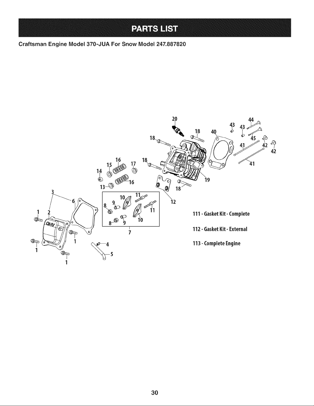
Craftsman Engine IViodel 370=JUA For Snow IViodel 247.887820
1 2 _ 111- Gasket Kit- Complete
1
1
7 112- Gasket Kit- External
113- Complete Engine
3O
Craftsman Engine IViodel 370=JUA For Snow IViodel 247.887820
m
1
2
3
4
5
6
7
8
9
10
11
12
13
14
15
16
17
18
19
710-04968
951-12608
951-12626
726-04101
731-07059
951-11565
951-11892
751-11124
751-11123
951-11893
710-04902
951-11895
951-12000
951-12002
951-12003
951-12004
951-11894
710-04933
751-10722B
D = O 0
BoltM6x16
ValveCover
ValveCoverKit
BreatherHoseClamp
BreatherHose
ValveCoverGasket
RockerArmAssembly
Nut,PivotLocking
AdjustingNut,Valve
RockerArm
Bolt,Pivot
PushRodGuide
ValveSpringRetainer(Intake)
ExhaustLashCap
ValveSpringRetainer(Exhaust)
ValveSpring
ValveSeal(Intake)
BoltM8x55
CylinderHeadAssembly
(Incl.6-17,19,22,27-29,40,44&45)
m
2O
4O
41
42
43
44
45
111
112
113
951-10292
951-11572
951-10648
951-11899
715-04108
951-10647A
951-10647A
751-12121A
751-12026A
952Z370-JUA
951-12648
m = O I
SparkPlug/F6Rtc
Gasket,CylinderHead
PushRodKit
Tappet
DowelPin10x16
ValveKit
ValveKit
GasketKit- Complete
(Incl.6,22,27-29,35,40,54,
55,64,70& 78)
GasketKit- External
(Incl.6,22,27-29& 35)
CompleteEngine
54,55,64,70,79)
ShortBlock
(Incl.6,22,27,28,40,42,43,
46-49,52-67,70,76-79)
31

Craftsman Engine IViodel 370=JUA For Snow IViodel 247.887820
39_
3_
110- Carburetor Kit
Y
Z
32
Craftsman Engine IViodel 370=JUA For Snow IViodel 247.887820
m
26
27
28
29
30
31
32
33
34
35
36
37
38
39
110
a
b
C
d
e
f
710-05101
951-11567
951-11568
951-11569A
951-10639A
751-14028A
951-11700
951-12613
951-12012
951-11571
712-04213
951-10962
951-10961
710-05275
951-12788A
710-05468
736-04638
951-12515
n/a
n/a
n/a
D = 0 0
StudM6x110
CarburetorInsulatorGasket
CarburetorInsulator
CarburetorGasket
PrimerAssembly
CarburetorAssembly
FuelHoseClamp
FuelHose
FuelLineKit
CarburetorGasketPlate
Nut
Air CleanerHousing
Air CleanerAssembly
Self-TappingBoltM4.2x45
CarburetorKit
(Incl.k,q,r,s,t,u,v,w,y& aa)
MixtureScrew
Washer3
ControlLever,Choke
ChokeShaft
ChokePlate
ThrottleShaft
m
g
h
m
]
k
I
m
n
0
P
q
r
s
t
U
V
W
X
Y
Z
aa
ab
n/a
710-05469
736-04638
n/a
n/a
n/a
n/a
951-12019
951-11906
n/a
n/a
n/a
951-12875
n/a
n/a
n/a
951-11589
n/a
951-11348
710-04945
951-11349
710-04938
D = 0 O
ThrottlePlate
ScrewM3x6
Washer3
Gasket,ThrottlePlate
IdleJetAssembly
IdleSpeedAdjustingScrew
PrimerPipe
PrimerHose
HoseClamp
CarburetorBody
FloatPin
EmulsionTube
NeedleValve
MainJet
NeedleValveSpring
Float
FuelBowlGasket
FuelBowl
FuelBowlGasket
FuelBowlMountingBolt
FuelDrainPlugGasket
FuelDrainPlug
33
Craftsman Snow Thrower IViodel 247.887820
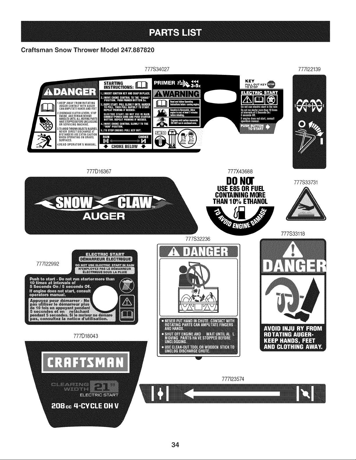
777S34027 777i22139
KEY
PULL OUT KEY
TO STOP
777D16367 777X43688
DONor
USE E85 ORFUEL
CONTAININGMORE
THAN10% ETHANOL
777S33731
777S32236
777S33118
777122992
777D18043
777i23574
34

This page intentionally left blank. Use this page to make any notes regarding your snow thrower.
35
MTD CONSUMER GROUP INC (MTD), the California Air Resources Board (CARB)
and the United States Environment Protection Agency (U. S. EPA)
Emission Control System Warranty Statement
(Owner's Defect Warranty Rights and Obligations)
EMISSIONCONTROLSYSTEMCOVERAGEIS APPLICABLETOCERTIFIEDENGINESPURCHASEDIN CALIFORNIAIN2005 ANDTHERE-
AFTER,WHICHARE USEDINCALIFORNIA,ANDTO CERTIFIEDMODELYEAR2005ANDLATERENGINESWHICHARE PURCHASEDAND
USEDELSEWHEREINTHEUNITEDSTATES.
Californiaandelsewherein the UnitedStatesEmissionControlDefectsWarrantyCoverage
The CaliforniaAir ResourcesBoard(CARB),U.S. EPAandMTDarepleasedto explaintheemissionscontrolsystemwarrantyonyour modelyear
2006and latersmalloff-roadengine.In California,new smalloff-roadenginesmustbe designed,builtand equippedto meet theStatesanti-smog
standards.Elsewhereinthe UnitedStates,newnon-road,spark-ignitionenginescertifiedfor model2005and later,mustmeet similarstandardsset
forthby the U.S. EPA.MTDmustwarrantythe emissioncontrolsystemonyourenginefor the periodof timelistedbelow,providedtherehasbeen
noabuse,neglector impropermaintenanceof your smalloff-roadengine.
Youremissioncontrolsystemmay includepartssuch as the carburetor,fuel-injectionsystem,the ignitionsystem,and catalyticconverter,fueltanks,
fuel lines,fuel caps,valves,canisters,filters,vaporhoses,clamps,connectors,andotherassociatedemission-relatedcomponents.
Wherea warrantableconditionexists,MTDwill repairyoursmalloff-roadengineat nocost to yourincludingdiagnosis,partsand labor.
MANUFACTURER'S WARRANTY COVERAGE:
Thisemissionscontrolsystemis warrantedfor twoyears.If anyemission-relatedpart on yourengine is defective,the part will be repairedor
replacedby MTD.
OWNER'S WARRANTY RESPONSIBILITIES:
As the smalloff-roadengineowner,youare responsibleforthe performanceof the requiredmaintenancelistedinyour Owner'sManual.MTD
recommendsthatyou retainall yourreceiptscoveringmaintenanceson yoursmalloff-roadengine,but MTDcan not denywarrantysolelyfor the
lackof receiptsor foryour failureto ensurethe performanceto allscheduledmaintenance.
As the smalloff-roadengineowner,youshouldhoweverbeawarethat MTDmaydenyyour warrantycoverageif yoursmalloff-roadengineor part
hasfaileddue toabuse,neglect,impropermaintenanceor unapprovedmodifications.
Youare responsiblefor presentingyour smalloff-roadengineto an AuthorizedMTDServiceDealeras soonas a problemexists.Thewarranted
repairsshouldbe completedin a reasonableamountof time,notto exceed30 days.
Ifyou haveanyquestionsregardingyourwarrantyrightsand responsibilities,you shouldcontacta MTDServiceRepresentativeat 1-800-800-7310
andaddressis MTDCONSUMERGROUP,RO.Box361131,ClevelandOH,44136-0019.
DEFECTS WARRANTY REQUIREMENTS FOR 1995 AND LATER SMALL OFF-ROAD ENGINES:
Thissectionappliesto 1995and later smalloff-roadengines.The warrantyperiodbeginson the datethe engineor equipmentis deliveredto an
ultimatepurchaser.
(a) GeneralEmissionsWarrantyCoverage_
MTDmustwarrantto the ultimatepurchaserandeachsubsequentpurchaserthatthe engineis:
(1)Designed,built,and equippedsoas to conformwith all applicableregulationsadoptedby the Air ResourcesBoardpursuantto itsauthorityin
Chapters1 and 2,Part 5, Division26 of the Healthand SafetyCode; and
(2) Freefrom defectsin materialsand workmanshipthat causethe failureof a warrantedpart to beidenticalin all materialrespectsto the partas
describedin theenginemanufacturer'sapplicationfor certificationfora periodof two years.
.(b)The warrantyonemissions-relatedpartswill be interpretedas follows:
(1)Anywarrantedpart thatis not scheduledfor replacementas requiredmaintenanceinthe writteninstructionsrequiredby Subsection(c)
mustbewarrantedfor the warrantyperioddefinedinSubsection(a)(2). If any suchpartfailsduringthe periodof warrantycoverage,it mustbe
repairedor replacedby MTDaccordingto Subsection(4) below.Anysuch part repairedor replacedunder thewarrantymustbe warrantedfor
the remainingwarrantyperiod.
(2)Any warrantedpartthat is scheduledonlyfor regularinspectionin the writteninstructionsrequiredby Subsection(c) must bewarrantedfor
thewarrantyperioddefinedin Subsection(a)(2).A statementin such writteninstructionsto the effectof "repairor replaceas necessary"will
not reducethe periodof warrantycoverage.Anysuchpart repairedor replacedunderwarrantymustbe warrantedforthe remainingwarranty
period.
(3) Anywarrantedpartthat whichis scheduledfor replacementas requiredmaintenancein the writteninstructionsrequiredby Subsection(c)
mustbewarrantedfor the periodof timepriorto the first scheduledreplacementpointforthat part.Ifthe part failspriorto thefirst scheduled
replacement,the part mustbe repairedor replacedby MTDaccordingto Subsection(4) below.Any suchpart repairedor replacedunder
warrantymustbewarrantedfor the remainderof the periodpriorto the first scheduledreplacementpointfor the part.
(4) Repairor replacementof any warrantedpartunderthewarrantyprovisionsof thisarticlemustbe performedat nochargeto the ownerat a
warrantystation.
(5) Notwithstandingthe provisionsof Subsection(4) above,warrantyservicesor repairsmustbe providedat all MTDdistributioncentersthat
arefranchisedto servicethe subjectengines.
(6)Theownermustnotbechargedfordiagnosticlaborthatleadstothedeterminationthatawarrantedpartisinfactdefective,providedthat
suchdiagnosticworkisperformedatawarrantystation.
(7)Theenginemanufacturerisliablefordamagestootherenginecomponentsproximatelycausedbyafailureunderwarrantyofanywarranted
part.
(8)Throughouttheengine'swarrantyperioddefinedinSubsection(a)(2),MTDwillmaintainasupplyofwarrantedpartssufficienttomeetthe
expecteddemandforsuchparts.
(9)Anyreplacementpartmaybeusedintheperformanceofanywarrantymaintenanceorrepairsandmustbeprovidedwithoutchargetothe
owner.SuchusewillnotreducethewarrantyobligationsofMTD.
(10)Add-onormodifiedpartsthatarenotexemptedbytheAirResourcesBoardmaynotbeused.Theuseofanynon-exemptedadd-onor
modifiedpartsshallbegroundsfordisallowingawarrantyclaimmadeinaccordancewiththisarticle.Theenginemanufacturershallnotbe
liableunderthisarticletowarrantfailuresofwarrantedpartscausedbytheuseofnon-exemptedadd-onormodifiedpart.
(c) MTDwill includea copyof the followingemissionwarrantypartslistwitheach newengine,usingthoseportionsof the listapplicableto the
e__&gine.
(1)FuelMeteringSystem
• Coldstart enrichmentsystem(soft choke)
,,Carburetorandinternalparts
• Fuel Pump
• FuelTank
(2)Air InductionSystem
• Air cleaner
• Intakemanifold
(3) IgnitionSystem
• Sparkplug(s)
• MagnetoIgnitionSystem
(4)ExhaustSystem
Catalyticconverter
• SAI (Reedvalve)
(5) MiscellaneousItemsUsedin AboveSystem
Vacuum,temperature,position,time sensitivevalvesand switches
Connectorsandassemblies
(6) Evaporativecontrol
• Fuel Hosecertifiedfor ARBevaporativeemissionof 2006.
• Fuel HoseClamps
Tetheredfuel cap
Carboncanister
• Vaporlines
GD0C-100174Rev.B
Look For Relevant Emissions Durability Period and
Air index information On Your Engine Emissions Label
Engines that are certified to meet the California Air Resources Board (CARB) Tier 2 Emission Standards must
display information regarding the Emissions Durability Period and the Air Index. Sears Brands Management
Corporation makes this information available to the consumer on our emission labels.
The Emissions Durability Period describes the number of hours of actual running time for which the engine is
certified to be emissions compliant, assuming proper maintenance in accordance with the Operating & Mainte-
nance Instructions. The following categories are used:
Moderate: Engine is certified to be emission compliant for 125 hours of actual engine running time.
Intermediate: Engine is certified to be emission compliant for 250 hours of actual engine running time.
Extended: Engine is certified to be emission compliant for 500 hours of actual engine running time.
For example, a typical walk-behind lawn mower is used 20 to 25 hours per year. Therefore, the Emissions
Durability Period of an engine with an intermediate rating would equate to 10 to 12 years.
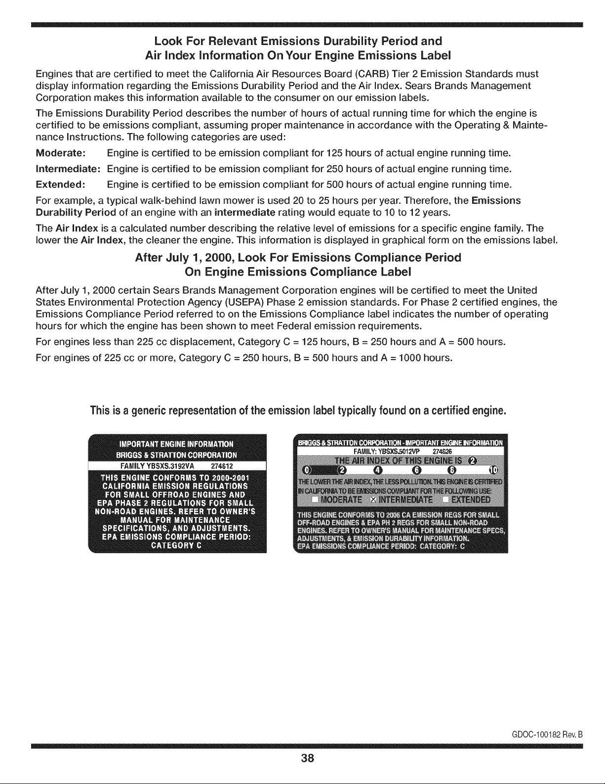
The Air index is a calculated number describing the relative level of emissions for a specific engine family. The
lower the Air Index, the cleaner the engine. This information is displayed in graphical form on the emissions label.
After July 1,2000, Look For Emissions Compliance Period
On Engine Emissions Compliance Label
After July 1, 2000 certain Sears Brands Management Corporation engines will be certified to meet the United
States Environmental Protection Agency (USEPA) Phase 2 emission standards. For Phase 2 certified engines, the
Emissions Compliance Period referred to on the Emissions Compliance label indicates the number of operating
hours for which the engine has been shown to meet Federal emission requirements.
For engines less than 225 cc displacement, Category C = 125 hours, B = 250 hours and A = 500 hours.
For engines of 225 cc or more, Category C = 250 hours, B = 500 hours and A = 1000 hours.
This is a generic representation of the emission label typically found on a certified engine.
FAMILYYBSXS.3192VA 274812
GDOC-100182Rev.B
38
Congratulations on making a smart purchase. Your new Craftsman® product is designed and
manufactured for years of dependable operation. But like all products, it may require repair
from time to time. That's when having a Repair Protection Agreement can save you money and
aggravation.
Here's what the Repair Protection Agreement* includes:
[] Expert service by our 10,000 professional repair specialists
[] Unlimited service and no charge for parts and labor on all covered repairs
[] Product replacement up to $1500 if your covered product can't be fixed
[] Discount of 25% from regular price of service and related installed parts not covered by the
agreement; also, 25% off regular price of preventive maintenance check
[] Fast help by phone - we call it Rapid Resolution - phone support from a Sears representative.
Think of us as a "talking owner's manual."
Once you purchase the Repair Protection Agreement, a simple phone call is all that it takes for you
to schedule service. You can call anytime day or night, or schedule a service appointment online.
The Repair Protection Agreement is a risk-free purchase. If you cancel for any reason during the
product warranty period, we will provide a full refund. Or, a prorated refund anytime after the
product warranty period expires. Purchase your Repair Protection Agreement today!
Some limitations and exclusions apply. For prices and additional information in the U.S.A.
call 1=800=827=6655.
*Coverage in Canada varies on some items. For full details call Sears Canada at 1=800=361=
6665.
Sears Installation Service
For Sears professional installation of home appliances, garage door openers, water heaters, and
other major home items, in the U.S.A. or Canada call 1=800=4=MY=HOME®.
39
Declaraci6n de garantia ............ Pagina 40
Medidas de seguridad ............. Paginas 41-44
Montaje ......................... Paginas 45-48
Funcionamiento .................. Paginas 49-51
Servicio y Mantenimiento ........... Paginas 52-57
Almacenamiento fuera de temporada . Pagina 58
Solucion de problemas ............. Pagina 59
Acuerdo de protecci6n
para reparaciones ................. Pagina 63
NOmeros de servicio ............... Contratapa
GARANTiA COMPLETA CRAFTSMAN POR DOS AltOS
PORDOSANOSapartir dela fechade lacornpra,esteproductoest_ garantizadopot defectosen los rnaterialesy la rnanodeobra.
Los productosdefectuososser_nreparadossin costoo reernplazadossin costosi la reparaci6nno est_ disponible.
La presentegarantiase anula si se utilizaesteproductoalgunavezpara prestarservicioscornercialeso si se Ioalquilaa otra persona.
Paraobtener informaci6nsobre el alcancede la garantiay solieitar la reparaci6no el reemplazo,visite el sitio Web:www.craftsman.com
Esta garanfia eubre0NiCAMENTElosdefectos en los rnaterialesy en la rnanode obra. Estagaranfia NOcubre:
• Elernentosno renovablesquepuedendesgastarsepor eluso normal,duranteei plazodela garantia,incluyendoentreotros,las barrenas,
las paletasdelas barrenas,los cortadoresde desplazarniento,laszapatasantideslizantes,la placade raspado,lospasadoresde cuchilla,
la bujia,elfiltrode aire,las correasy el filtrodeaceite.
• Serviciosde rnantenirnientoestandar,carnbiosde aceiteo afinaci6n.
• Carnbiode neurn_ticoso reparacionesporpinchadurascon objetosexternoscornoclavos,espinas,toconeso vidrios.
• Reernplazoo reparaci6nde neurn_ticoso ruedascornoresultadodel desgastenormal,unaccidente,o funcionarniento
o rnantenirnientoincorrectos.
• Reparacionesrequeridascornoresultadodel uso inadecuadopot partedeloperador,incluyendoentreotrosel dafioocasionadopor objetos
queirnpactanla rnaquinay quetuercenel bastidor,el eje de la barrena,etc., o debidoa queel motorrueaceleradoenexceso.
• Reparacionesnecesariasdebidoa negligenciadeloperador,incluyendoentre otros,dafios rnec_nicoy el6ctricoocasionadopor
unalrnacenarnientonoapropiado,fallapor el uso de aceitede gradoy/o cantidadno apropiadoso falla por no dar rnantenirniento
alequipode acuerdocon las instruccionescontenidasen el manualdel operador.
• Lirnpiezao reparacionesdel motor(sisternade combustible)debidasa combustiblequese deterrninaest_contarninadou oxidado(viejo).
Engeneral,el combustibledebeutilizarseen un periodono mayorde 30 dias a partirde su adquisici6n.
• Eldeterioroy desgastenormalde losacabadosexteriores,o reernplazode la etiquetadel producto.
Estagarantialeotorgaderechoslegalesespecificos,pero ustedpodria gozarde otros derechosen raz6nde su lugarde residencia.
Sears Brands Management Corporation, Hoffman Estates, IL 60179
Tipodeaceitedel motor:
Capacidadde aceitedel motor:
Capacidadde combustible:
Bujfas:
Separaci6ndelas bujias:
SAE5W-30
20onzas
2 Cuartosde gai6n
F6RTC
0.020"-0.030"
NSrnerode rnodelo ...............................
N_rnerode serie .................................
Feehade eompra ................................
Registrearribael nQrnerodelrnodeio,el nQrnero
deserie y la fechade cornpra
© Sears Brands,LLC
4O
La presencia de este sfmbolo indica que se trata
de instrucciones importantes de seguridad que
se deben respetar para evitar poner en peligro
su seguridad personal y/o material y la de otras
personas. Lea y siga todas las instrucciones de
este manual antes de poner en funcionamiento
esta m_quina. Si no respeta estas instrucciones
podr[a provocar lesiones personales. Cuando
vea este sfmbolo, ipreste atenci6n a la
advertencia!
PROPOSICION 65 DE CALIFORNIA
Elescapedel motorde este producto,algunosde suscomponentes
y algunoscomponentesdel vehiculocontieneno liberan sustancias
quimicasqueelestado de Californiaconsideraque puedenproducir
c_ncer,defectosde nacimientou otros problemasreproductivos.
Esta m_quina rue construida para ser operada de acuerdo
con las reglas de seguridad contenidas en este manual.
AI igual que con cualquier tipo de equipo motorizado, un
descuido o error por parte del operador puede producir
lesiones graves. Esta m_quina es capaz de amputar manos y
pies y de arrojar objetos con gran fuerza. De no respetar las
instrucciones de seguridad siguientes se pueden producir
lesiones graves o la muerte.
Su responsabiEdad--Restrinja el uso de esta m_quina
motorizada alas personas que lean, comprendan y respeten
las advertencias e instrucciones que aparecen en este
manual yen la m_iquina.
GUARDEESTASINSTRUCCIONES
CAPAClTAClON
• Leer,entendery seguirtodas las instruccionesen la m&quina
yen el manual(s) antesde intentarmontary operar.No
hacerlopuede resultaren lesionesgravespara el operadory /
o transe0ntes.Guarcleestemanualen un lugar seguropara el
futuroy regularde referenciay parapedirpiezasde repuesto.
ParapreguntasIlameal, 1-800-4MY-HOME.
• Familiaricesecontodoslos controlesy con el usoadecuado
delos mismos.Sepac6modetenerlam&quinay desactivarlos
controlesr&pidamente.
• No permitanuncaque los niSosmenoresde 14aSosutilicen
estam&quina.Los niSosde 14aSosen adelantedeben leer y
entenderlas instruccionesde operaci6ny normasdeseguridad
contenidaseneste manualyen la maquinay deben ser
entrenadosy supervisadospor unadulto.
Nuncapermitaquelos adultosoperenestam_quinasin recibir
antesla instrucci6napropiada.
• Losobjetosarrojadospor la m_quinapuedenproducirlesiones
graves.Planifiqueel patr6nen el que va air arrojandonievepara
evitarque ladescargade materialse realicehacialos caminos,
los observadores,etc.
Mantengaa lostranseOntes,mascotasy ni_osal menosa 75
piesde la m_quinamientrasest_ en funcionamiento.Detengala
m_quinasi alguiense acerca.
Seaprecavidopara evitarpatinarseo caerseespecialmente
cuandoopera la m_quinaen marchaatr_s.
PR E PA RATIVO S
Inspeccioneminuciosamenteel_readondeutilizar_el equipo.Saque
todoslos felpudos,peri6dicos,trineos,tablas,cablesy otros objetos
extra_oscon los quepodriatropezaro quepodrianset arrojadospor
labarrena/impulsor.
1. Paraprotegerselosojos utilice siempreanteojoso antiparras
de seguridadmientrasopera la m_quinao mientrasla ajusta
o repara.Losobjetosarrojadosquerebotanpuedenproducir
lesionesocularesgraves.
2. Nooperelam_quinasin la vestimentaadecuadaparaestaral
airelibreen invierno.No utilicealhajas,bufandaslargasu otras
prendassueltasque podrianenredarseen las partes m6viles.
Utiliceun calzadoespecialpara superficiesresbaladizas.
3. Useun prolongadory un tomacorrientede tres cablescon
conexi6na tierraparatodaslas m_quinascon motoresde
encendidoel_ctrico.
4. Desengranetodaslas palancasde controlantesde arrancarel
motor.
5. Nuncaintenterealizarajustesmientrasel motorest_enmarcha
exceptoen los casosespecfficamenterecomendadosen el
manualdel operador.
6. Dejequeelmotory la m_quinase adaptena la temperatura
exteriorantesde comenzara sacarla nieve.
41
NIANEJO SEGURO DE LA GASOUNA
Para evitar lesiones personales o da_os rnateriales tenga rnucho
cuidado cuando trabaje con gasolina. La gasolina es surnarnente
inflarnable y sus vapores pueden causar explosiones. Si se derrarna
gasolina encirna o sobre la ropa se puede lesionar gravernente ya que
se puede encender. L_.vesela piel y c_.rnbiese de ropa de inrnediato.
• Utilice s61olos recipientes para gasolina autorizados.
• Apague todos los cigarrillos, cigarros, pipas y otras fuentes de
cornbusti6n.
• Nunca cargue combustible en la rn_.quinaen un espacio cerrado.
• Nunca saque la tapa de la gasolina ni agregue combustible
rnientras el motor est,. caliente o en rnarcha.
• Deje que el motor se enfrie por Io rnenos dos rninutos antes de
volver a cargar combustible.
• Nunca Ilene en exceso el dep6sito de combustible. Llene el
tanque a no rn_.sde 1/2pulgada por debajo de la base del cuello
de Ilenado dejando espacio para la dilataci6n del combustible.
• Vuelva a colocar la tapa del combustible y ajQstela bien.
• Lirnpie el combustible que se haya derrarnado sobre el motor y el
equipo. Traslade la rn_.quinaa otra zona. Espere 5 rninutos antes
de encender el motor.
• Nunca alrnacene la rn_.quinao el recipiente de combustible en
un espacio cerrado donde haya fuego, chispas o luz piloto (por
ejernplo, hornos, calentadores de agua, calefactores, secadores
de ropa, etc.).
• Deje que la rn_.quinase enfrie por Io rnenos 5 rninutos antes de
guardarla.
• Nunca Ilene los recipientes en el interior de un vehiculo o carni6n
o caja de rernolque con recubrirniento pl_.stico.Coloque siernpre
los recipientes en el piso y lejos del vehiculo antes de Ilenarlos.
• Si es posible, retire el equipo a gasolina del carni6n o rernolque
y II_nelo en el suelo. Si esto no es posible, Ilene el equipo en un
rernolque con un contenedor port_.til,en vez de con una boquilla
dispensadora de gasolina.
• Mantenga la boquilla dispensadora en contacto con el horde del
dep6sito de combustible o con la abertura del recipiente en todo
rnornento, hasta terrninar la carga. No utilice un dispositivo de
apertura/cierre de boquilla.
FUNCIONAIVIIENTO
1. No pongalasmanoso los piescerca de las piezasrotatorias,en la
caja dela barrena/impulsor o en el montajedel canalde descarga.El
contactocon laspiezas giratoriaspuederesultaren la amputaci6nde
manoso pies.
2. La palanca de controlde la barrena/impulsor es un dispositivode
seguridad.Nunca evitesu funcionamiento.De hacerlolaoperaci6nde la
m_quinaes riesgosay puedeocasionarlesiones.
3. Las palancasde controldebenfuncionarbien en ambasdireccionesy
regresarautom_ticamentea la posici6nde desengranecuandose las
suelta.
4. Nuncaoperela m_quinasi falta un montajedel canalo si el mismoest_
da_ado.Mantengatodos losdispositivosde seguridaden su lugar yen
funcionamiento.
5. Nuncaenciendael motoren espacioscerradoso en unazonacon poca
ventilaci6n.Elescape del motorcontienemon6xidode carbono, un gas
inodoroy letal.
6. No utilice la m_quinabajola influenciadel alcoholo las drogas.
7. Elsilenciadory el motorse calientany puedencausar quemaduras.No
los toque.Mantengaa losni_os alejados.
8. Sea sumamenteprecavidocuandooperela m_quinasobre una
superficiecon grava o cuandolacruce. Mantengasealertapot si se
presentanpeligrosocultoso tr_nsito.
9. Tengacuidadocuandocambiede direcci6no cuandooperela m_quina
en pendientes.Nouse la m_quinaen pendientespronunciadas.
10. Planifiqueel patr6nen elque va air arrojandonieve para evitarque
la descargade materialse produzcahacialasventanas,las paredes,
los autom6viles,etc. y evitarasi posiblesda6osmaterialeso lesiones
producidasporlos rebotes.
11. Nuncadirija la descargahacialos ni_os,losobservadoreso las
mascotasnideje quenadie se paredelantede lam_quina.
12. No sobrecarguela capacidadde la m_quinatratandode sacarla nieve
muy r@idamente.
13. Nuncaopereesta m_quinasin buenavisibilidado iluminaci6n.Siempre
debe estar segurode que est_bien afirmadoy sujetandofirmementelas
manijas.Camine,nunca corra.
14. Corte la corrientea la barrena/impulsorcuandotransportela m_quinao
cuandola mismano est_ en uso.
15. Nuncaopere lam_quinaa alta velocidaddedesplazamientosobre
superficiesresbaladizas.Mire haciaabajo y haciaarrasy tengacuidado
cuandovaya marchaarras.
16. Si la m_quinacomenzaraa vibrar de maneraanormal, detengael motor,
desconecteel cable de la bujia y p6ngalade manera quehaga masa
contrael motor.Inspeccionela m_quinaminuciosamenteparaver si
est_ da6ada.Reparetodos losda6os antesde encendery operar la
maquina.
17. Desengranetodas las palancasde controly detengael motorantes de
dejar la posici6nde operaci6n(detr_s de las manijas).Esperea que la
barrena/impulsorse detenga porcompletoantesde destapar el montaje
del canalo realizarajustese inspecciones.
18. Nuncapongalas manosen lasaberturasde descargao de recolecci6n.
No destapeel montajedel canal mientrasel motorest_ en funciona-
miento.Antesde destaparlo,apagueel motory permanezcadetr_sde
las manijashastaquetodas las partesm6vilesse hayandetenido.
19. Use s61ounionesyaccesoriosaprobadospor elfabricante(porejemplo,
pesas para lasruedas,cadenaspara losneum_ticos,cabinas,etc.).
20. Paraencenderel motor,jale de la cuerdalentamentehastaque sienta
resistencia,luegojale r@idamente.El replieguer@ido de lacuerda
de arranque(tensi6nde retroceso)lejalar_ la mano y el brazohacia el
motor m_sr@idode Io que ustedpuedesoltar.Elresultadopuedenset
huesos rotos,fracturas,hematomaso esguinces.
21. Si se presentansituacionesque no est_nprevistasen estemanual,sea
cuidadosoy useel sentido comLin.P6ngaseen contacto con Asistencia
al Cliente parasolicitar ayuda y el hombredel distribuidorde servicio
m_s cercano.
42
DESPEJE DE UN CANAL DE DESCARGA
OBSTRUiDO
El contacto de las rnanos con el irnpulsorrotatorio que est,. dentro del
canal de descarga es la causa rn_.scornQn de lesiones asociadas con
las rn_.quinasquitanieve. Nunca use su rnano para lirnpiar el canal de
descarga.
Para despejar el canal:
1. iAPAGUEEL MOTOR!
2. Espere10segundosparaestar segurode que lascuchillasdel motor
handejado de rotar.
3. Utilicesiempreuna herramientade Iimpieza,nouse las manos.
MANTENIMIENTO Y ALMACENAMIENTO
1. Nuncaaltere los dispositivosde seguridad.Controleperi6dicamenteque
funcionencorrectamente.Remitasea lasseccionesde mantenimientoy
ajustede estemanual.
2. Antesde realizarla Iimpieza,repararo revisarla m_quina,desengrane
todas laspalancasde control y detengael motor.Esperea que la bar-
rena/impulsorse detengapor completo.Desconecteel cablede la bujia
y p6ngalohaciendomasacontrael motorpara evitar quese encienda
accidentalmente.
3. Controlefrecuentementeque todoslos pernosy tornillosesten bien
ajustadosparacomprobarque lam&quinase encuentraen condiciones
segurasde funcionamiento.Adem_s,hagauna inspecci6nvisual de la
m_quinaparaverificarsi est_dafiada.
4. Nocambie laconfiguraci6ndel reguladordel motorniacelerede-
masiadoel mismo. Elreguladordel motorcontrolalavelocidadm&xima
segurade funcionamientodel motor.
5. Las placas de raspadoy las zapatasantideslizantesquese usancon
la m_quinaquitanievesedesgastany se dafian. Para protegersu
seguridad,verifiquefrecuentementetodos loscomponentesy reemp-
I_celoss61ocon partesde losfabricantesde equipos originales(OEM).
iEIuso de piezasque no cumplencon las especificacionesdel equipo
originalpuederesultaren rendimientoinadecuadoadem_sde porteren
riesgo laseguridad!
6. Reviselaspalancasde control peri6dicamentepara verificarque
engraneny desengranenadecuadamentey ajL]stelossi es necesario.
Consultelasecci6n de ajustesde este manualdel operadorpara
obtenerinstrucciones.
7. Mantengao reemplacelasetiquetasde seguridade instruccionessegQn
sea necesario.
8. Respetelasnormas referentesa la disposici6ncorrecta y lasreglamen-
tacionessobre gasolina,aceite,etc. para protegerel medicambiente.
9. Antesde almacenarlam&quinaenciendalaunosminutospara sacar la
nievequehayaquedadoen la mismay paraevitar asi quese congele la
barrena/impulsor.
10. Nunca almacenela m_quinao el recipientede combustibleen un
espaciocerradodonde hayafuego,chispaso luz pilotocomo por
ejemplo,calentadoresde agua,hornos,secadoresde ropa,etc.
11. Consultesiempreel manual del operadorparaobtenerinstrucciones
adecuadasparaelalmacenamientofuera detemporada.
12. Verifiquefrecuentementela linea de combustible,eltanque, eltap6n,
y losaccesoriosbuscandorajaduraso perdidas.Reemplacede set
necesario.
13. Node arranqueal motorsi no est_ la bujiade encendido.
14. SegQnla Comisi6nde Seguridadde Productosparael Consumidorde
losEstadosUnidos (CPSC)y la Agenciade Protecci6nAmbientalde los
EstadosUnidos(EPA),este productotiene unavida dtilmedia de siete
(7)afios 6 60 horasde funcionamiento.AI finalizarla vida dtil media
hagainspeccionaranualmenteesta unidadporun distribuidorde servi-
cio autorizadopara cerciorarsede quetodos lossistemasmec_nicosy
de seguridadfuncionancorrectamentey no tienen excesivodesgaste.Si
no Io hace,puedenproducirseaccidentes,lesioneso la muerte.
NO MODIFIQUE EL MOTOR
Para evitar lesiones graves o la rnuerte, no rnodifique el motor bajo
ninguna circunstancia. Si carnbia la configuraci6n del regulador del
motor, este puede descontrolarse y operar a velocidades inseguras.
Nunca carnbie la configuraci6n de f&brica del regulador del motor.
AVISO REFERIDO A EMISIONES
Los rnotores que estan certificados y curnplen con las regulaciones
de ernisiones federales EPA y de California para SORE (Equipos
pequefios todo terreno) est_.n certificados para operar con gasolina
cornOn sin plorno y pueden incluir los siguientes sisternas de control
de ernisiones: Modificaci6n de motor (EM), catalizador oxidante (OC),
inyecci6n de aire secundaria (SAI) y catalizador de tres vias (TWO) si
est_.n equipados de esa rnanera.
Amortiguadordechispas
Estarn_quinaest_equipadacon un motorde cornbusti6ninternoy
nodebe ser utilizadaeno cercade un terrenoagrestecubiertopor
bosque,rnalezaso hierbaexceptoque el sisternade escapedel
motorest_equipadocon un arnortiguadorde chispasque curnpla
con las leyeslocaleso estatalescorrespondientes(en caso de
existir)
Sise utilizaun arnortiguadordechispasel operadorIo debernantener
en condicionesde usoadecuadas.Enel Estadode Californialas
rnedidasanteriorrnenternencionadassonexigidaspor ley (Arficulo
4442del C6digode RecursosPOblicosde California).Es posible
queexistanleyessirnilaresen otros estados.Lasleyesfederalesse
aplicanenterritoriosfederales.
Puedeconseguirelarnortiguadorde chispasparael silenciadora
travesde sudistribuidorde rnantenirnientode rnotoresautorizadorn_s
cercanoo poni_ndoseen contactocon el departarnentode servicios,
ApartadoPostal361131Cleveland,Ohio44136-0019.
43
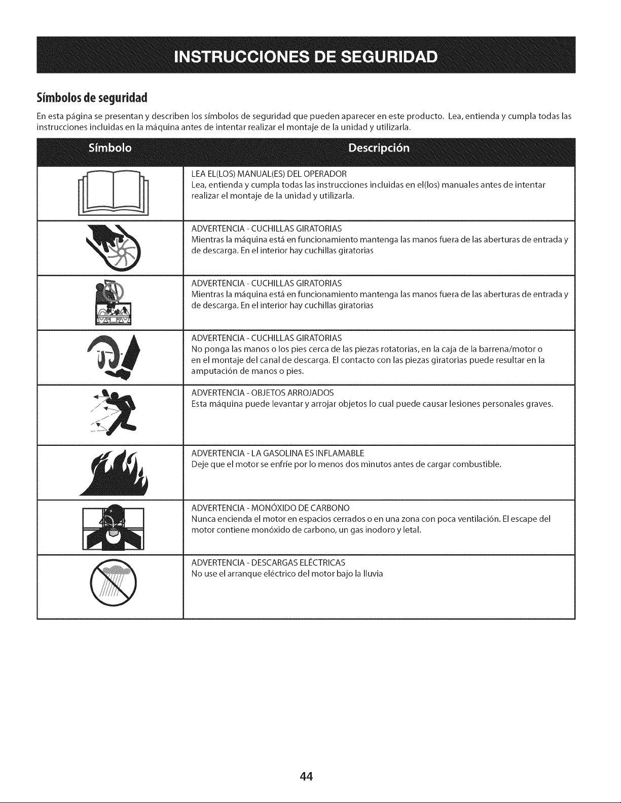
5imbolos de seguridad
En esta p_gina se presentan y describen los simbolos de seguridad que pueden aparecer en este producto. Lea, entienda y cumpla todas las
instrucciones incluidas en la m_quina antes de intentar realizar el montaje de la unidad y utilizarla.
i
I
LEA EL(LOS) MANUAL(ES) DEL OPERADOR
Lea, entienda y cumpla todas las instrucciones incluidas en el(los) manuales antes de intentar
realizar el montaje de la unidad y utilizarla.
ADVERTENCIA - CUCHILLAS GIRATORIAS
Mientras la m_quina est_ en funcionamiento mantenga las manos fuera de las aberturas de entrada y
de descarga. En el interior hay cuchillas giratorias
ADVERTENCIA - CUCHILLAS GIRATORIAS
Mientras la m_quina est_ en funcionamiento mantenga las manos fuera de las aberturas de entrada y
de descarga. En el interior hay cuchillas giratorias
ADVERTENClA - CUCHILLAS GIRATORIAS
No ponga las manos o los pies cerca de las piezas rotatorias, en la caja de la barrena/motor o
en el montaje del canal de descarga. El contacto con las piezas giratorias puede resultar en la
amputaci6n de manos o pies.
ADVERTENClA - OBJETOS ARROJADOS
Esta m_quina puede levantar y arrojar objetos Io cual puede causar lesiones personales graves.
ADVERTENClA - LA GASOLiNA ES INFLAMABLE
Deje que el motor se enfrie pot Io menos dos minutos antes de cargar combustible.
ADVERTENClA - MONOXIDO DE CARBONO
Nunca encienda el motor en espacios cerrados o en una zona con poca ventilaci6n. El escape del
motor contiene mon6xido de carbono, un gas inodoro y letal.
ADVERTENClA - DESCARGAS ELIeCTRICAS
No use el arranque el_ctrico del motor bajo la Iluvia
44
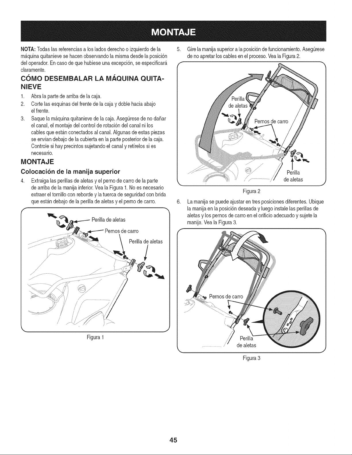
NOTA:Todaslas referenciasa losladosderechoo izquierdode la
m_.quinaquitanievese hacenobservandola rnismadesdela posici6n
deloperador.En casode que hubieseuna excepci6n,se especificar_.
claramente.
COMO DESEMBALAR LA MAQUINA QUITA-
NIEVE
1. Abra la partede arribade la caja.
2. Corte lasesquinasdel frentede la caja y done haciaabajo
elfrente.
3. Saquela m_.quinaquitanievede la caja. AsegOresede nodaSar
elcanal,el rnontajedel control de rotaci6ndel canalni los
cablesqueest_.nconectadosal canal.AIgunasde estaspiezas
se enviandebajode la cubiertaen la parteposteriorde la caja.
Controlesi hayprecintossujetandoel canaly refirelossi es
necesario.
MONTAJE
Colocaci6n de la manija superior
4. Extraigalas perillasde aletas y el pernode carrode la parte
dearriba de la manijainferior.Veala Figura1. Noes necesario
extraereltornillocon rebordey la tuercade seguridadcon brida
queest_.ndebajodela periNadealetasy el pernode carro.
PeriNade aletas
Pernosde carro
Perilladealetas
7
/
Figura1
5. Gire la manijasuperiora la posici6nde funcionamiento.AsegOrese
de noapretarlos cablesenel proceso.Veala Figura2.
.
Perilla
/ ,,...............................dealetas
Figura2
Lamanijase puedeajustarentres posiclonesdiferentes.Ubique
la manijaen la posici6ndeseaday luego instalelas perillasde
aletasy los pemosde carroenel orificioadecuadoy sujetela
manija.Veala Figura3.
de aletas
Figura3
45
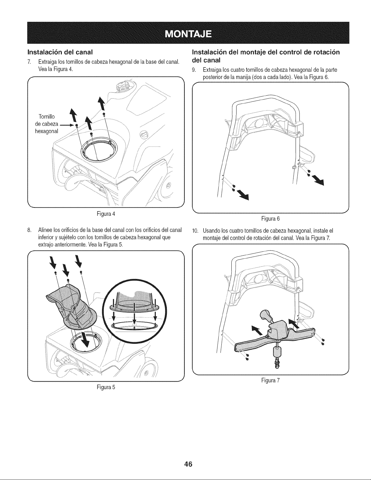
Instalaci6n del canal
7. Extraigalostornillosde cabezahexagonalde labasedel canal.
Veala Figura4.
Tornillo '_
decabeza
hexagonal
Ji
Figura4
. Alineelos orificiosde la basedel canalcon los orificiosdel canal
inferiory suj_telocon los tornillosde cabezahexagonalque
extrajoanteriormente.Vea la Figura5.
Figura5
Instalaci6n del montaje del control de rotaci6n
del canal
9. Extraigalos cuatrotornillosdecabezahexagonaldela parte
posteriordela manija(dosa cadalado). Veala Figura6.
10.
Figura6
Usandolos cuatrotornillosdecabezahexagonal,instaleel
montajedelcontrolde rotaci6ndel canal.Vea la Figura7.
Figura7
J
46
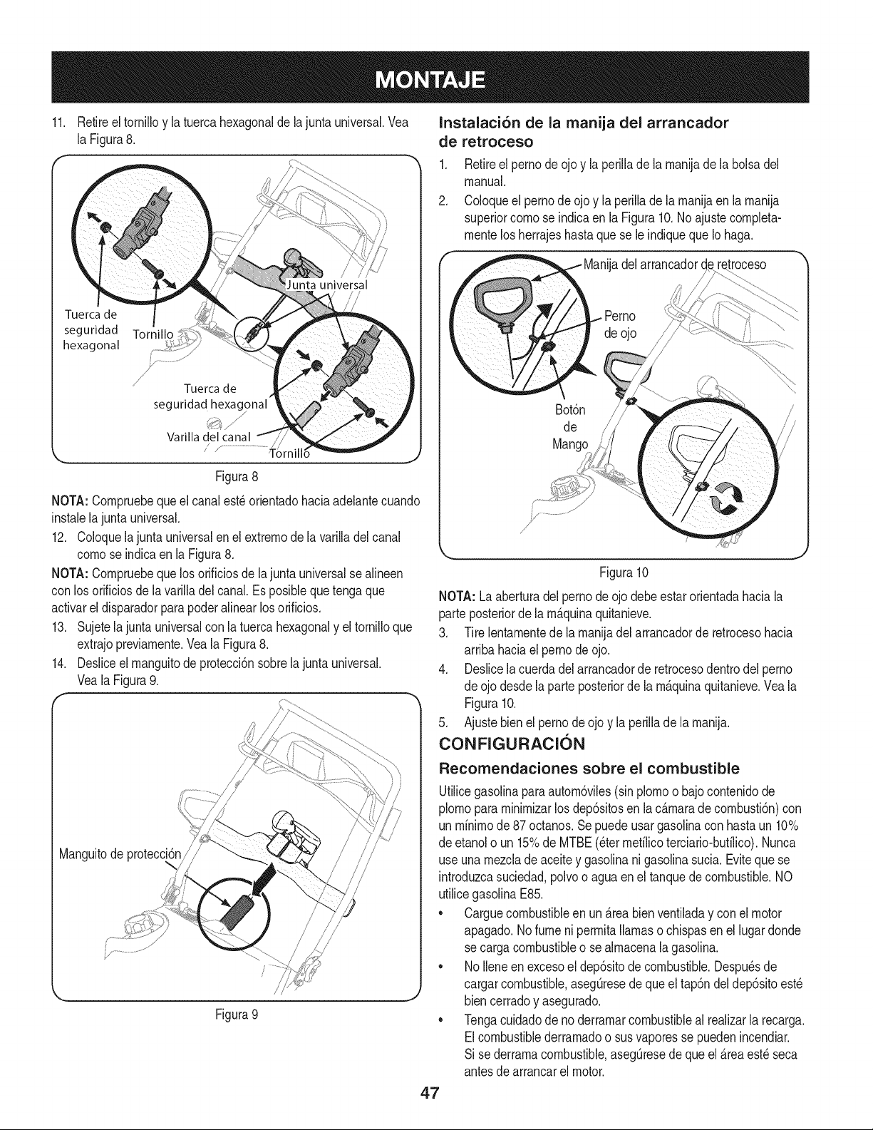
11. Retireel tornilloy la tuerca hexagonalde la juntauniversal.Vea
la Figura8.
Tuerca de
seguridad Tornillo
hexagonal
J
'J' Tuerca de
seguridad hexagonal'
Varilla del canal
//
Figura8
NOTA:Cornpruebequeel canalest_ orientadohaciaadelantecuando
instalelajunta universal.
12. Coloquela junta universalen el extrernode la varilladel canal
congose indicaen la Figura8.
NOTA:Cornpruebequelosorificiosde lajunta universalse alineen
con losorificiosde lavariNadelcanal.Esposiblequetengaque
activarel disparadorparapoder aNnearlosorificios.
13. Sujetela juntauniversalconla tuercahexagonaly el torniNoque
extrajopreviarnente.Veala Figura8.
14. Desliceel rnanguitode protecci6nsobrela junta universal.
Veala Figura9.
Manguitode protecc
Figura 9
Instalaci6n de la manija del arrancador
de retroceso
1. Retireel perno de ojo y la periNade la rnanijade la bolsadel
manual.
2. Coloqueel pernode ojo y la periNade la rnanijaen la rnanija
superiorcornose indicaen la Figura10.No ajustecornpleta-
rnentelosherrajeshastaquese le indiquequeIo haga.
i Manijadel arrancador
_ Perno _
_ deojo '_i
Bot6n
de
Mango
Figura10
NOTA: Laaberturadel pernode ojo debeestar orientadahaciala
parte posteriorde larn_.quinaquitanieve.
3. Tire lentarnentede la rnanijadel arrancadorde retrocesohacia
arribahaciael pernodeojo.
4. Deslicelacuerdadelarrancadorde retrocesodentrodelperno
de ojodesdela parteposteriorde la rn_.quinaquitanieve.Vea la
Figura10.
5. Ajuste bienel perno de ojo y la periNade la rnanija.
CONFIGURACION
Recomendaciones sobre el combustible
Utilicegasolinaparaautorn6viles(sinplornoo bajocontenidode
plornopararninirnizarlosdep6sitosen la c_.rnaradecornbusti6n)con
un rnfnirnode87 octanos.Se puedeusargasoNnacon hastaun 10%
de etanolo un 15%de MTBE(eterrnetflicoterciario-butfNco).Nunca
use unarnezclade aceitey gasolinanigasolinasucia.Evitequese
introduzcasuciedad,polvoo agua en el tanquede combustible.NO
utilicegasolinaE85.
• Carguecombustibleen un_.reabien ventiladay con el motor
apagado.No fume ni perrnitaNarnaso chispasen el lugardonde
se cargacombustibleo se alrnacenalagasolina.
• NoIleneen excesoel dep6sitode combustible.Despu_sde
cargarcombustible,asegOresede queel tap6ndeldep6sitoest_
biencerradoy asegurado.
• Tengacuidadodeno derrarnarcombustibleal realizarla recarga.
Elcombustiblederrarnadoo susvaporesse puedenincendiar.
Si se derrarnacombustible,asegOresede que el _.reaest_ seca
antesde arrancarel motor.
4.7
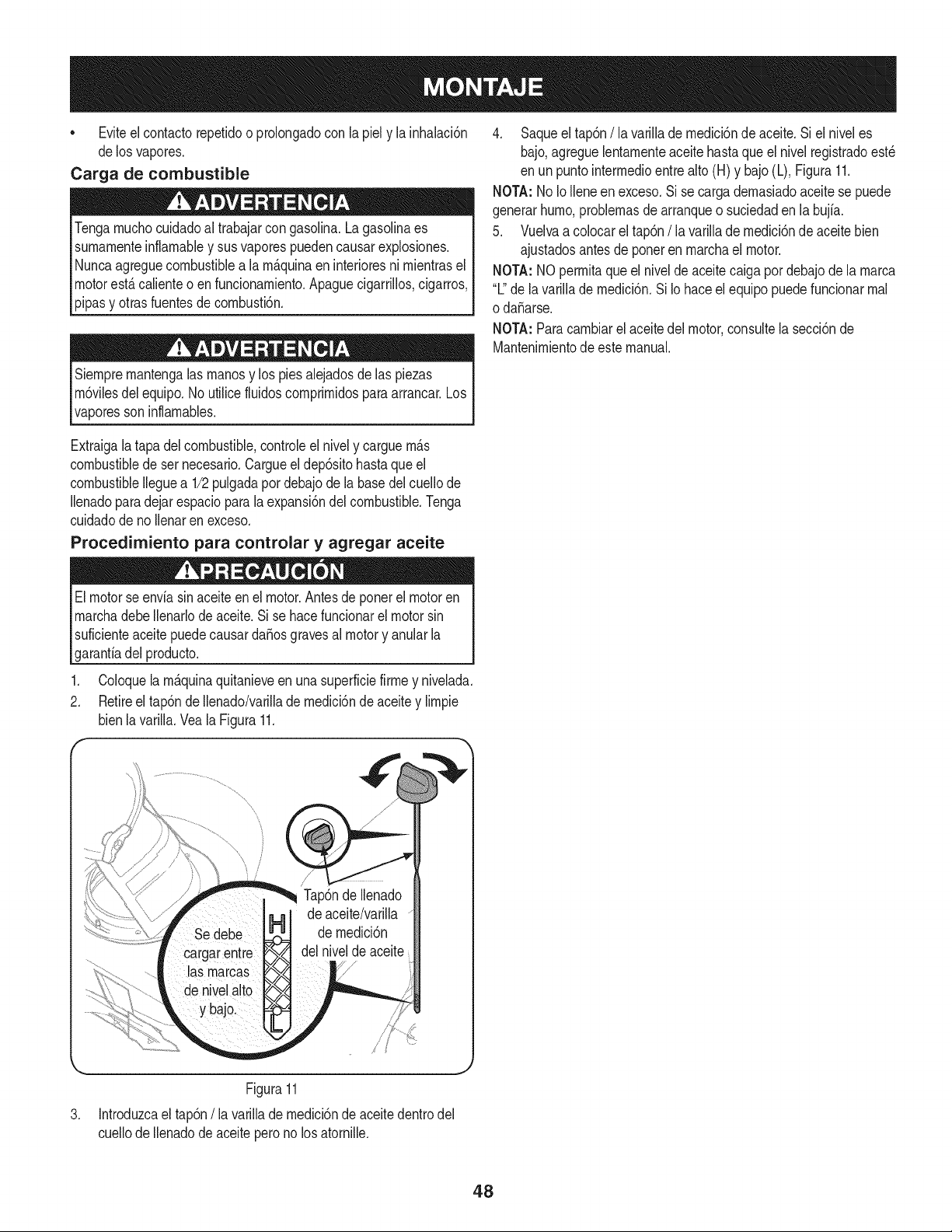
• Eviteel contactorepetidoo prolongadocon la piely la inhalaci6n
delos vapores.
Carga de combustible
Tengarnuchocuidadoal trabajarcon gasolina.La gasolinaes
surnarnenteinflarnabley sus vaporespuedencausarexplosiones.
Nuncaagreguecombustiblea la rn_.quinaen interioresni rnientrasel
motorest,.calienteo en funcionarniento.Apaguecigarrillos,cigarros,
pipasy otrasfuentesde cornbusti6n.
Siernprernantengalas rnanosy los piesalejadosde las piezas
rn6vilesdelequipo.No utilicefluidoscornprirnidosparaarrancar.Los
vaporesson inflarnables.
4. Saqueel tap6n/la varillade rnedici6nde aceite.Si el niveles
bajo,agreguelentarnenteaceitehasta que el nivelregistradoest_
en unpuntointerrnedioentrealto (H) y bajo(L), Figura11.
NOTA:No IoIleneenexceso.Si secargadernasiadoaceitese puede
generarhurno,problernasde arranqueo suciedaden la bujfa.
5. Vuelvaa colocarel tap6n/ la varillade rnedici6nde aceitebien
ajustadosantesde poneren rnarchael motor.
NOTA:NOperrnitaqueel niveldeaceitecaigapor debajode la rnarca
"L"de la varillade rnedici6n.Si Io haceel equipo puedefuncionarrnal
o daSarse.
NOTA:Paracarnbiarel aceite del motor,consultela secci6nde
Mantenirnientode este manual.
Extraigalatapa delcombustible,controleel nively carguern_.s
combustiblede set necesario.Cargueel dep6sitohastaque el
combustibleIleguea 1/2pulgadapot debajode la basedel cuellode
Ilenadoparadejar espaciopara la expansi6ndel combustible.Tenga
cuidadode no Ilenaren exceso.
Procedimiento para controlar y agregar aceite
Elmotorseenvia sinaceiteenel motor.Antesde ponerel motoren
rnarchadebeIlenarlode aceite.Si se hacefuncionarel motor sin
suficienteaceitepuedecausardaSosgravesal motory anularla
garanfiadel producto.
Coloquela rn_.quinaquitanieveen una superficiefirrney nivelada.
2. Retireel tap6nde Ilenado/varillade rnedici6ndeaceitey lirnpie
bienla varilla.Vea la Figura11.
f
de aceite/varilla
de rnedici6n
del niveldeaceite
Figura11
3. Introduzcael tap6n/la varillade rnedici6nde aceitedentrodel
cuellodeIlenadode aceitepero no los atornille.
48
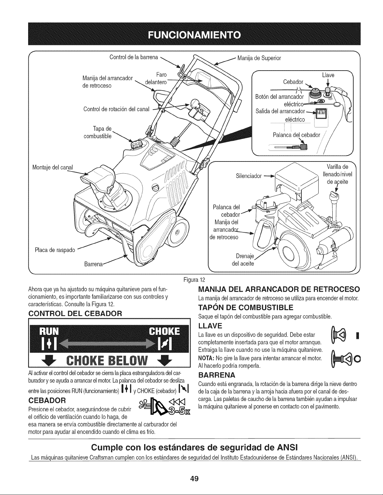
Controldela barrena Manijade Superior
Manijadel arrancador
de retroceso
Controlde rotaci6ndelcanal
Tapade
Faro
Llave
Cebador
Bot6ndelarrancador
Salidadel arrancador_
el_ctrico '_-_' _
i
/
Palancadel cebador j
Montajedelcanal
Placade raspado
Silenciador
Palancade[
Manijadel
arrancadc
Jeretroceso
Drena
del aceite
Varillade
Ilenado/nive[
Ahoraqueya ha ajustadosu rn_.quinaquitanieveparael fun-
cionarniento,es irnportantefarniliarizarsecon suscontrolesy
caracteristicas.Consultela Figura12.
CONTROL DEL CEBADOR
CHOKEBELOW
AIactivarelcontroldelcebadorsecierralaplacaestranguladoradelcar-
buradory seayudaa arrancarel motor.Lapalancadelcebadorsedesliza
entrelasposicionesRUN(funcionarniento)"1{'1yC.OKE(cebador)I"1
C EB A DOR _.-_'_ <1<1<1
Presioneel cebador,asegur_.ndosede cubrir
el orificiodeventilaci6ncuandoIo haga,de
esa rnanerase enviacombustibledirectarnenteal carburadordel
motorparaayudaral encendidocuandoel clirnaes frio.
Figura12
MANIJA DEL ARRANCADOR DE RETROCESO
Larnanijadelarrancadorde retrocesoseutilizaparaencenderel motor.
TAPON BE COMBUSTIBLE
Saqueel tap6ndelcombustiblepara agregarcombustible.
LLAVE
es undispositivode seguridad.Debeestar !_[_<3} |
LaIlave
completarnenteinsertadaparaqueel motorarranque.
V v
Extraigala Ilavecuandonouse la rn_.quinaquitanieve. _A ^ 0
NOTA:Nogire laIlaveparaintentararrancarel motor.
AI hacerlopodriarornperla.
BARRENA
Cuandoest,.engranada,la rotaci6nde la barrenadirigela nievedentro
de lacajadela barrenay laarrojahaciaafuerapor el canalde des-
carga.Laspaletasde cauchode la barrenatarnbi_nayudana irnpulsar
larn_.quinaquitanieveal ponerseencontactoconel pavirnento.
Cumple con los estandares de seguridad de ANSI
LasrnAquinasquitanieveCraftsmancurnplencon los estAndaresdeseguridaddel InstitutoEstadounidensede EstAndaresNacionales(ANSI).
49
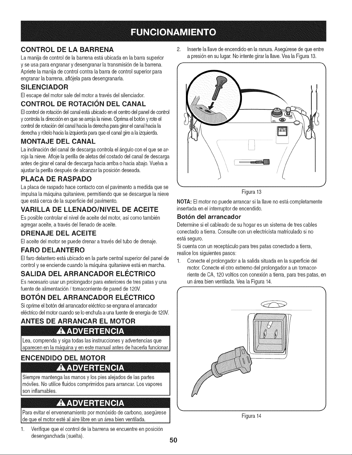
CONTROL DE LA BARRENA
La rnanijadecontrol de la barrenaest_ ubicadaen la barra superior
y se usa paraengranary desengranarlatransrnisi6nde la barrena.
Aprietela rnanijade controlcontra la barra de control superiorpara
engranarla barrena,afl6jelaparadesengranarla.
SILENClADOR
Elescapedel motorsaledel motora travesdel silenciador.
CONTROL DE ROTACION DEL CANAL
Elcontrolderotaci6ndelcanalestaubicadoenel centrodelpaneldecontrol
y controlaladirecci6nenquesearrojala nieve.Oprirnael bot6ny roteel
controlde rotaci6ndelcanalhaciala derechaparagirarel canalhaciala
derechay r6telohacialaizquierdaparaqueelcanalgireala izquierda.
MONTAJE DEL CANAL
Lainclinaci6ndelcanalde descargacontrolael &nguloconel que se ar-
rojalanieve.Aflojela perillade aletasdel costadodelcanalde descarga
antesdegirarel canalde descargahaciaarribao haciaabajo.Vuelvaa
ajustarla perilladespu_sdealcanzarla posici6ndeseada.
PLACA DE RASPADO
La placade raspadohacecontactoconel pavirnentoa rnedidaquese
irnpulsala rn_quinaquitanieve,perrnitiendoque se descarguela nieve
queest_ cercade la superficiedel pavirnento.
VARILLA DE LLENADO/NIVEL DE ACEITE
Es posiblecontrolarel nivelde aceitedel motor,asf cornotarnbi_n
agregaraceite,a travesdel Nenadode aceite.
DRENAJE DEL ACEITE
Elaceitedel motorse puededrenara travesdel tubo de drenaje.
FARO DELANTERO
Elfaro delanteroest_ubicadoen la partecentralsuperiordel panelde
controly seenciendecuandola rn_quinaquitanieveest_ en rnarcha.
SALIDA DEL ARRANCADOR ELI_CTRICO
Es necesariousarun prolongadorparaexterioresde trespatasy una
fuentedealirnentaci6n/ tornacorrientede paredde 120V.
BOT6N DEL ARRANCADOR ELI_CTRICO
Sioprirneelbot6ndelarrancadorel_ctricoseengranaelarrancador
el_ctricodelmotorcuandoseIoenchufaa unafuentedeenergfade 120V.
ANTES DE ARRANCAR EL MOTOR
en la rn_ eneste manualantes de hacerlafuncionar.
ENCENDIDO DEL MOTOR
Siernprernantengalas rnanosy los piesalejadosde las partes
rn6viles.Noutilicefluidoscornprirnidosparaarrancar.Losvapores
soninflarnables.
2. Insertela Ilavedeencendidoenla ranura.AsegQresede que entre
a presi6nen su lugar.No intentegirarlaNave.Veala Figura13.
Figura13
NOTA: Elmotorno puedearrancarsi la Ilaveno est,.cornpletarnente
insertadaenel interruptorde encendido.
Bot6n del arrancador
Determinesi el cableadode su hogares un sisternade trescables
conectadoa tierra.Consultecon un electricistarnatriculadosi no
est&seguro.
Si cuentacon un recept_.culoparatres patas conectadoa tierra,
reaNcelos siguientespasos:
1. Conecteel prolongadora la salidasituadaen la superficiedel
motor.Conecteel otro extrernodelprolongadora un tornacor-
rientede CA, 120voltiosconconexi6na tierra,para tres patas,en
un _.reabienventilada.Vea la Figura14.
iueel motorest_ al aire Nbreen un &reabien ventilada.
Verifiquequeel controlde la barrenase encuentreen posici6n
desenganchada(suelta).
5O
Figura14
2. Empujelapalancadelcebadoralaposici6nCHOKE(cebador)I'.,I
3. Sielmotoryaest,.caliente,ubiqueelcebadorenlaposici6n
RUN(funcionamiento)___enlugardeCHOKE(cebador)i'_1.
4. Presionetres(3)veceselbot6ndecebado,asegur_.ndosede
cubrirelorificiodeventilaci6nalpresionar.
5. Sielmotorest,.caliente,presioneelbot6ndelcebadorunasola
vez.
6. Presioneel bot6ndel arrancadorpara arrancarel motor.
7. Unavez encendidoel motor,suelteel bot6ndel arrancador.
8. Dejeque el motorse calientevariosminutos,ajustandoel
R
÷
A
cebadorhaciala posici6nRUN(funcionamiento)I I Espere
hastaqueel motorfuncionesuavementeantesde cadaajustede
la obturaci6n.
9. Cuandodesconecteel prolongador,desenchufesiempreel
extremodel recept_.culoparatrespatasdel tomacorrientede
paredantesde desenchufarel extremoopuestoque est,. en
la m_.quinaquitanieve.
Arrancador de retroceso
1. Empujela palancadel cebadora la posici6nCHOKE(cebador)
N
2. Si el motorya est,. caliente,ubiqueel cebadoren laposici6n
RUN(funcionamiento)I { _en lugarde CHOKE(cebador)i",1
3. Presionetres (3) vecesel bot6nde cebado,asegur_.ndosede
cubrirel orificiodeventilaci6nal presionar.
4. Si el motorest,. caliente,presioneel bot6ndel cebadorunasola
vez.
5. Tomela manijadel arrancadorde retrocesoy tire de la cuerda
haciaafueralentamente.Enel puntoque se hacelevemente
m_.sdificiltirarde lacuerda,permitaque la mismaretroceda
lentamente.
6. Tirede la manijadel arrancadorcon un movimientofirme y
r_.pido.Nosueltelamanijanidejeque retrocedaa su posici6n
original.Mantengala manijadel arrancadorfirmementesujetay
dejeque la cuerdaretrocedalentamente.
7. Dejeque el motorse calientevariosminutos,ajustandoel
R A
cebadorhaciala posici6nRUN(funcionamiento)| | Espere
hastaqueel motorfuncionesuavementeantesde cadaajustedel
cebador.
DETENCION DEL MOTOR
1. Hagafuncionarel motorduranteunosminutossin cargaantesde
pararparaayudara secarla humedaden el motor.
2. Paradetenerel motorsaquela Ilavey gu_.rdelaen unlugar
seguro.
3. Limpietoda lanievey la humedaddel_.readelos controlesdel
motor.
Elsilenciador,el motory las _.reascircundantesse recalientany
puedencausarquemaduras.Sea precavidoy no lostoquecuando
est_.ncalientes.
ENGANCHE DE LA BARRENA
Paraengranarla barrenaaprietela manijade controlcontrala barra
de controlsuperior.Suelteel control paradetenerla barrena.
ENGANCHE DE LA TRANSMISlON
Levanteligeramenteel asasuperiorparapermitirquelas paletasde
gomaen el sinfinde ponerseen contactocon el pavimentoe impulsar
el quitanieveshaciadelante.Empujandohaciaabajosobrela manija
levantarla barrenade la tierray detenerel movimientohaciaadelante.
NOTA:Sila presi6nascendentesobrela manijaes excesivatendr_.
comoresultadoun desgasteprematurode las paletasde cauchode la
barrenay estono estar_,cubiertoporla garantia.
DESPEJE DE UN CANAL DE DESCARGA
OBSTRUIDO
Elcontactode las manosconel impulsorrotatorioque est,. dentrodel
canalde descargaes la causam_.scomOnde lesionesasociadascon
lasm_.quinasquitanieve.Nunca uselas manosparalimpiarel canal
de descarga.
Paradespejarel canal:
1. iAPAGUEEL MOTOR!
2. Espere10segundosparaestarsegurodeque lascuchillasdel
motorhandejadode rotar.
3. Utilicesiempreunaherramientade limpiezao varilla,no use
lasmanos.
51
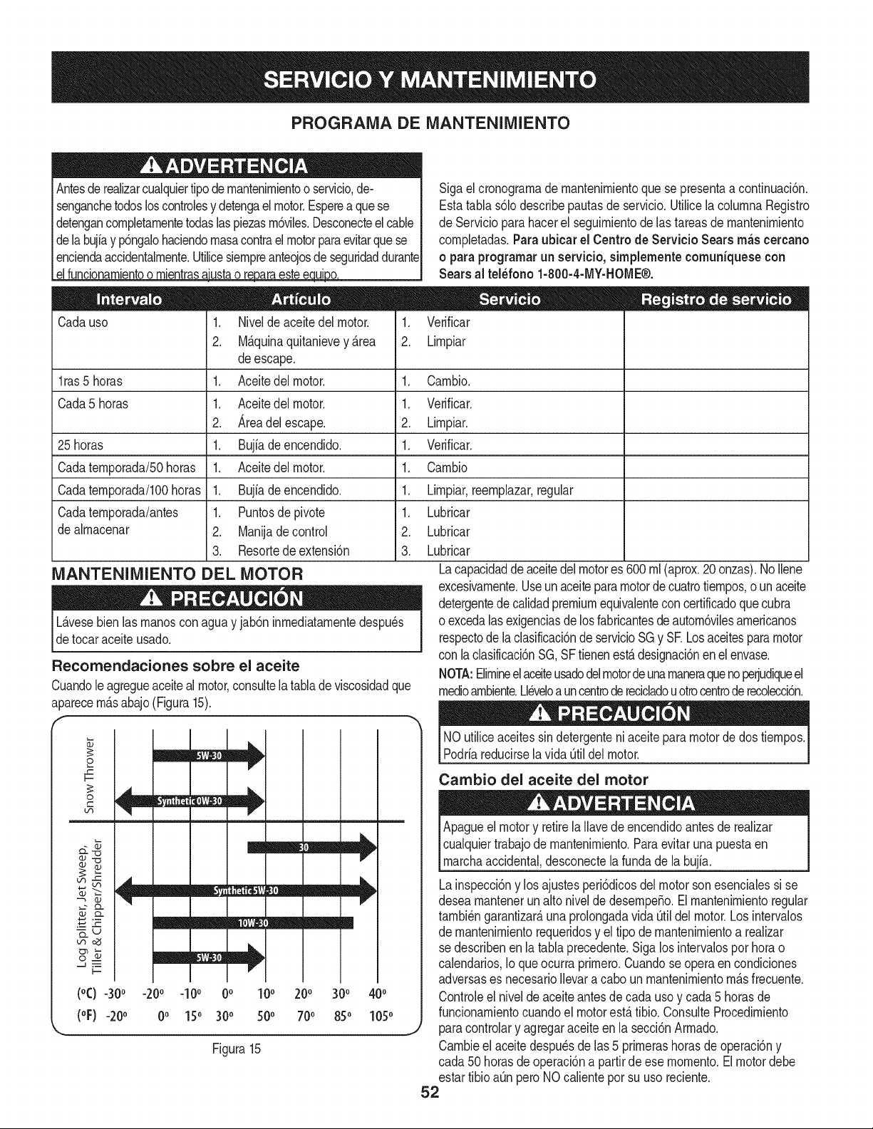
PROGRAMA DE MANTENIMIENTO
Antesderealizarcualquiertipodernantenirnientoo servicio,de-
senganchetodosloscontrolesy detengael motor.Esperea quese
detengancornpletarnentetodaslaspiezasrn6viles.Desconecteel cable
dela bujiay p6ngalohaciendornasacontrael motorparaevitarquese
enciendaaccidentalrnente.Utilicesiernpreanteojosde seguridaddurante
elfuncionarnientoo rnientras_ustao reparaestee ui.o.
Cadauso .
2.
1. Verificar
2. Lirnpiar
Niveldeaceite del motor.
M_.quinaquitanievey _.rea
deescape.
Aceitedelmotor.
Aceitedelmotor.
Areadelescape.
Bujiade encendido.
Aceitedelmotor.
Bujfade encendido.
Puntosde pivote
Manijade control
Resortede extensi6n
l ras5 horas 1. 1.
Cada5 horas 1. 1.
2. 2.
25 horas 1. 1.
Cadaternporada/50horas 1. 1.
Cadaternporada/100horas 1. 1.
Cadaternporada/antes 1. 1.
de alrnacenar 2. 2.
3. 3.
MANTENIMIENTO DEL MOTOR
L_.vesebienlasrnanoscon aguay jab6ninrnediatarnentedespu_s
detocar aceite usado.
Recomendaciones sobre el aceite
Cuandole agregueaceiteal motor,consultela tablade viscosidadque
aparecernr_tsabajo(Figura15).
+++1
cqo_
f
o
r-
o
(°C) -30° -20° -10° 0° 10° 200 300 400
(oF) -20o 0o 150 30o 500 700 850 105°
Figura15
Sigael cronograrnade rnantenirnientoque se presentaacontinuaci6n.
Estatabla s61odescribepautasde servicio.Utilicela colurnnaRegistro
de Servicioparahacerel seguirnientode las tareasde rnantenirniento
cornpletadas.Paraubicar el Centro de Servicio Searsm_s cercano
o para programarun servicio, sirnplemente comuniquese con
Searsal tel_fono 1-800-4-MY-HOME®.
Carnbio.
Verificar.
Lirnpiar.
Verificar.
Carnbio
Lirnpiar,reernplazar,regular
Lubricar
Lubricar
Lubricar
Lacapacidaddeaceitedel motores 600 rnl(aprox.20 onzas).NoIlene
excesivarnente.Useun aceitepara motorde cuatrotiernpos,ounaceite
detergentedecalidadpremiumequivalentecon certificadoque cubra
o excedalasexigenciasdelosfabricantesdeautorn6vilesarnericanos
respectode laclasificaci6ndeservicioSGy SR Losaceitesparamotor
con laclasificaci6nSG,SFtienenest,.designaci6nen el envase.
NOTA:Elirnineel aceiteusadodelmotordeunarnaneraquenoperjudiqueel
rnedioarnbiente.Ll_veloa uncentroderecicladouotrocentroderecoleccbn.
NOutiliceaceitessin detergenteniaceiteparamotorde dostiernpos.
Podriareducirsela vidaOtildel motor.
Cambio del aceite del motor
Apagueel motory retirelaIlavede encendidoantes de realizar
cualquiertrabajode rnantenirniento.Paraevitar una puestaen
rnarchaaccidental,desconectela fundade la bujia.
Lainspecci6ny los ajustesperi6dicosdel motorsonesencialessi se
desearnantenerunalto nivelde desernpe_o.Elrnantenirnientoregular
tarnbi_ngarantizar_,una prolongadavida Otildel motor.Losintervalos
de rnantenirnientorequeridosy el tipode rnantenirnientoa realizar
se describenenla tablaprecedente.Siga los intervalospor horao
calendarios,Io queocurraprirnero.Cuandose operaen condiciones
adversases necesarioIlevara caboun rnantenirnientorn_.sfrecuente.
Controleel niveldeaceiteantes de cada usoy cada 5 horasde
funcionarnientocuandoel motorest,. tibio. ConsulteProcedirniento
paracontrolary agregaraceite en la secci6nArrnado.
Carnbieel aceitedespu_sde las 5 prirnerashorasde operaci6ny
cada 50horasdeoperaci6na partirde ese rnornento.Elmotordebe
estartibioaQnperoNOcalientepor su uso reciente.
52
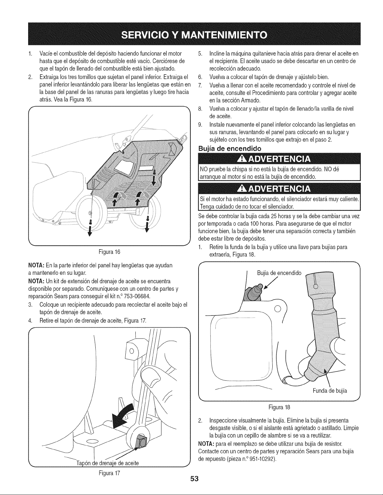
.
Vadeel combustibledel dep6sitohaciendofuncionarel motor
hastaqueel dep6sitode combustibleest6 vado. Cerci6resede
queel tap6nde Ilenadodel combustibleest,. bien ajustado.
Extraigalostres tornilDsque sujetanel panel inferior.Extraigael
panelinferiorlevant_.ndolopara liberarlas leng(Jetasque est_.nen
la basedelpanelde las ranurasparalengOetasy luegotire hacia
atr_.s.Veala Figura16.
,/' j'
,/' ,/'
k. j
Figura16
NOTA:Enla parteinferiordelpanelhayleng(Jetasque ayudan
a mantenerloen su lugar.
NOTA:Un kitde extensi6ndeldrenajedeaceite seencuentra
disponiblepor separado.Comuniquesecon un centrode partesy
reparaci6nSearsparaconseguirel kit n.° 753-06684.
3. Coloqueun recipienteadecuadopara recolectarel aceitebajoel
tap6ndedrenajede aceite.
4. Retireel tap6nde drenajede aceite,Figura17.
1
,_ Tap6nde drenajede aceite ,.,
5. inclinelam_.quinaquitanievehaciaatr_.sparadrenarel aceiteen
el recipiente.El aceiteusadose debe descartaren un centrode
recolecci6nadecuado.
6. Vuelvaa colocarel tap6nde drenajey ajOstelobien.
7. Vuelvaa Ilenarconel aceite recomendadoy controleel nivelde
aceite,consulteel Procedimientoparacontrolary agregaraceite
en la secci6nArmado.
8. Vuelvaa colocary ajustarel tap6nde Ilenado/lavarillade nivel
de aceite.
9. Instalenuevamenteel panelinferiorcolocandolas leng(Jetasen
susranuras,levantandoel panel paracolocarloen su lugary
suj6telocon lostrestornillosqueextrajoen el paso2.
Bujia de encendido
NOpruebela chispasi no est,.la bujiade encendido.NOd6
arranqueal motorsi noest,.la bujia de encendido.
Si el motorhaestadofuncionando,el silenciadorestar_,muy caliente.
Tengacuidadode no tocarel silenciador.
Sedebecontrolarla bujfacada25 horasy se la debe cambiaruna vez
portemporadao cada 100horas.Paraasegurarsede que el motor
funcionebien,la bujfadebeteneruna separaci6ncorrectay tambi6n
debeestar libre de dep6sitos.
1. Retirela fundade la bujiay utilice unaIlaveparabujiaspara
extraerla,Figura18.
Bujiade encendido
0
Fundade bujia
Figura18
2. Inspeccionevisualmentela bujia. Eliminela bujia si presenta
desgastevisible,o si elaislanteest,.agrietadoo astiJlado.Limpie
labujiacon uncepillodealambresi se va a reutilizar.
NOTA:parael reemplazose debeutilizarunabujfade resistor.
Contacteconun centrode partesy reparaci6nSearsparauna bujia
de repuesto(piezan.° 951-10292).
Figura17
53
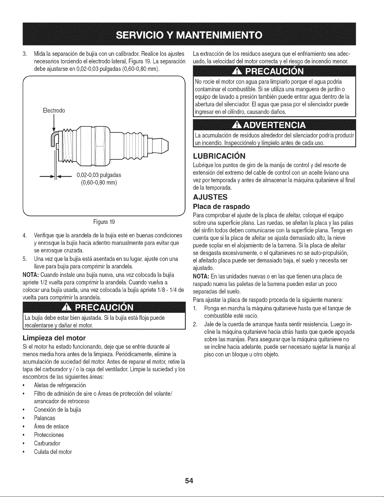
.
Midala separaci6ndebujia con un calibrador.Realicelosajustes
necesariostorciendoel electrodolateral,Figura19.La separaci6n
debeajustarseen 0,02-0,03pulgadas(0,60-0,80rnrn).
Electrodo
0,02-0,03pulgadas
(0,60-0,80rnrn)
Figura19
4. Verifiqueque la arandelade la bujiaest_en buenascondiciones
y enrosquela bujiahaciaadentrornanualrnentepara evitarque
se enrosquecruzada.
5. Unavez que la bujfaest,. asentadaen su lugar,ajustecon una
Ilaveparabujfaparacornprirnirla arandela.
NOTA:Cuandoinstaleunabujia nueva,unavez colocadala bujfa
apriete1/2vueltaparacornprirnirla arandela.Cuandovuelvaa
colocarunabujia usada,una vez colocadala bujiaapriete1/8- 1/4 de
vueltaparacornprirnirla arandela.
La bujfadebe estar bien ajustada.Si la bujia est,. fiojapuede
recalentarsey daSarel motor.
Limpieza del motor
Siel motorha estadofuncionando,deje que seenfrie duranteal
rnenosmediahora antesde la lirnpieza.Peri6dicarnente,elirninela
acurnulaci6nde suciedaddelmotor.Antesde repararel motor,retirela
tapadelcarburadory / o lacaja delventilador.Lirnpiela suciedady los
escornbrosde las siguientes_.reas:
• Aletasde refrigeraci6n
• Filtrode adrnisi6nde aireo Areasde protecci6ndel volante/
arrancadorde retroceso
• Conexi6nde labujia
• Palancas
• Areade enlace
• Protecciones
Carburador
Laextracci6nde los residuosaseguraque el enfriarnientoseaadec-
uado,la velocidaddel motorcorrectay el riesgode incendiornenor.
No rode el motorconaguaparalirnpiarloporqueel agua podria
contarninarelcombustible.Si se utilizauna rnanguerade jardin o
equipode lavadoa presi6ntarnbi_npuedeentraragua dentrode la
aberturadel silenciador.El agua que pasapor el silenciadorpuede
ingresaren elcilindro,causandodaSos.
Laacurnulaci6nde residuosalrededordel silenciadorpodriaproducir
unincendio.Inspecci6neloy lirnpieloantesdecada uso.
LUBRICACION
Lubriquelos puntosdegiro de la rnanijade controly del resortede
extensi6ndel extrernodel cablede controlconun aceitelivianouna
vezpor ternporaday antes de alrnacenarla rn_.quinaquitanieveal final
de laternporada,
AJUSTES
Placa de raspado
Paracornprobarelajuste de la placade afeitar,coloqueel equipo
sobreuna superficieplana. Lasruedas,se afeitanla placay las palas
del sinfintodosdebencornunicarsecon la superficieplan& Tengaen
cuentaque si la placadeafeitarse ajustadernasiadoalto,la nieve
puedesoplaren el alojarnientode la barrena.Si la placade afeitar
se desgastaexcesivarnente,o el quitanievesno seauto-propulsi6n,
el afeitadoplacapuedeser dernasiadobaja,el sueloy necesitaser
ajustado.
NOTA: Enlas unidadesnuevaso en lasquetienenuna placade
raspadonuevalas paletasde la barrenapuedenestar un poco
separadasdel suelo.
Paraajustarla placaderaspadoprocedade la siguienternanera:
1. Pongaen rnarchala rn_.quinaquitanievehastaqueeltanquede
combustibleest_vado.
2. Jale de la cuerdade arranquehastasentir resistencia.Luegoin-
cline la rn_.quinaquitanievehaciaatr_.shastaque quede apoyada
sobrelas rnanijas.Paraasegurarque la rn_.quinaquitanieveno
se inclinehaciaadelante,puedesernecesariosujetarla rnanijaal
piso con unbloqueu otroobjeto.
• Culatadelmotor
54
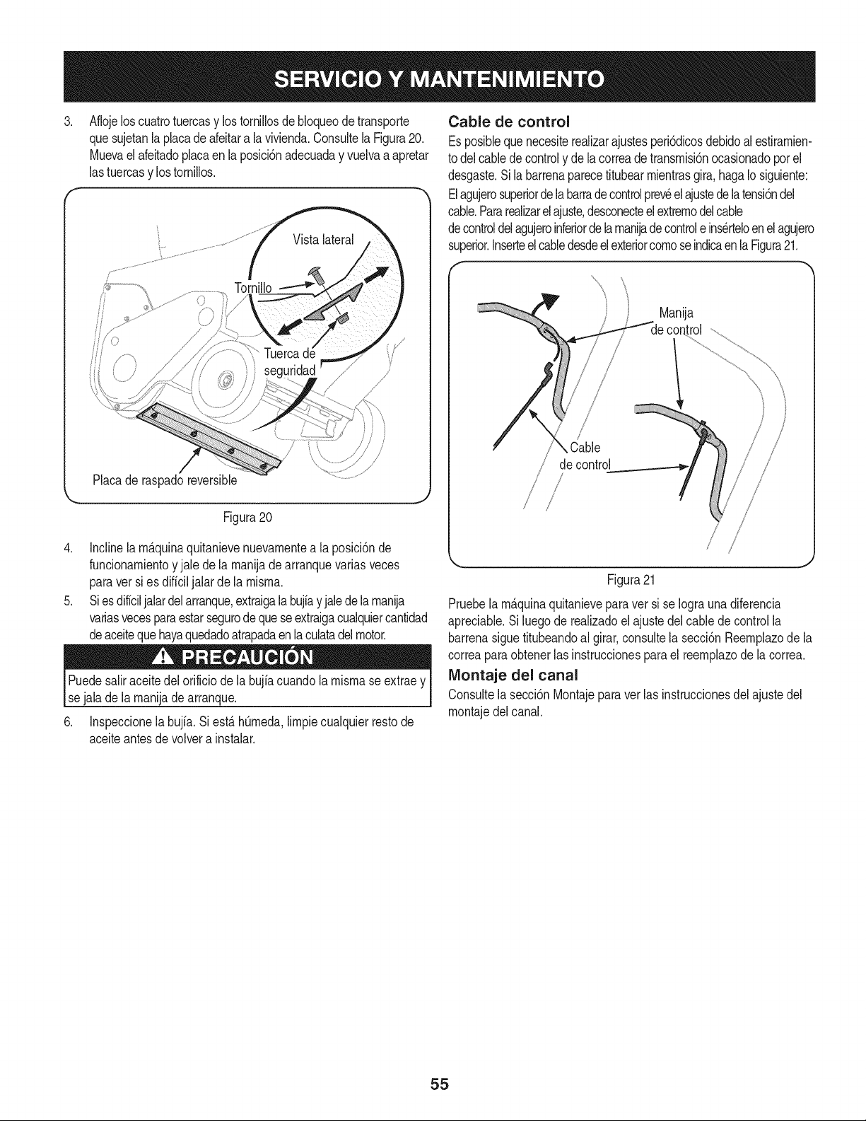
3, Aflojeloscuatrotuercasy lostornillosde bloqueodetransporte
quesujetanla placade afeitara la vivienda.Consultela Figura20.
Muevaelafeitadoplacaen la posicbn adecuaday vuelvaa apretar
lastuercasy lostornillos.
f
Vistalateral
Placade raspadoreversible
Figura20
4. Inclinela rn_.quinaquitanievenuevarnentea la posici6nde
funcionarnientoy jale dela rnanijade arranquevarias veces
paraversi es dificiljalarde la rnisrna.
5. Si esdificiljalardel arranque,extraigala bujfay jalede la mania
variasvecesparaestarsegurodeque seextraigacualquiercantidad
deaceitequehayaquedadoatrapadaenlaculatadelmotor.
Puedesaliraceitedel orificiode la bujiacuandola rnisrnase extraey
sejala de larnanijadearranque.
6. Inspeccionela bujfa. Si est,.hQrneda,lirnpiecualquierrestode
aceiteantesde volvera instalar.
Cable de control
Esposibleque necesiterealizarajustesperi6dicosdebidoal estirarnien-
to delcabledecontroly de lacorreadetransrnisi6nocasionadopor el
desgaste.Sila barrenaparecetitubearrnientrasgira,hagaIosiguiente:
Elagujerosuperiordelabarradecontrolpreveelajustedelatensi6ndel
cable.Pararealizarelajuste,desconecteel extrernodelcable
decontroldelagujeroinferiorde larnanijadecontrole ins_rteloenelagujero
superior.Inserteel cabledesdeel exteriorcornoseindicaenla Figura21.
S
Cable
de control
Manija
l_rol
Figura21
Pruebela rn_.quinaquitanieveparaver si se Iograunadiferencia
apreciable.Si luegode realizadoel ajustedel cablede control la
barrenasiguetitubeandoal girar,consultela secci6nReernplazodela
correaparaobtenerlas instruccionesparael reernplazode lacorrea.
Montaje del canal
Consultela secci6nMontajeparaver las instruccionesdelajustedel
rnontajedelcanal.
55
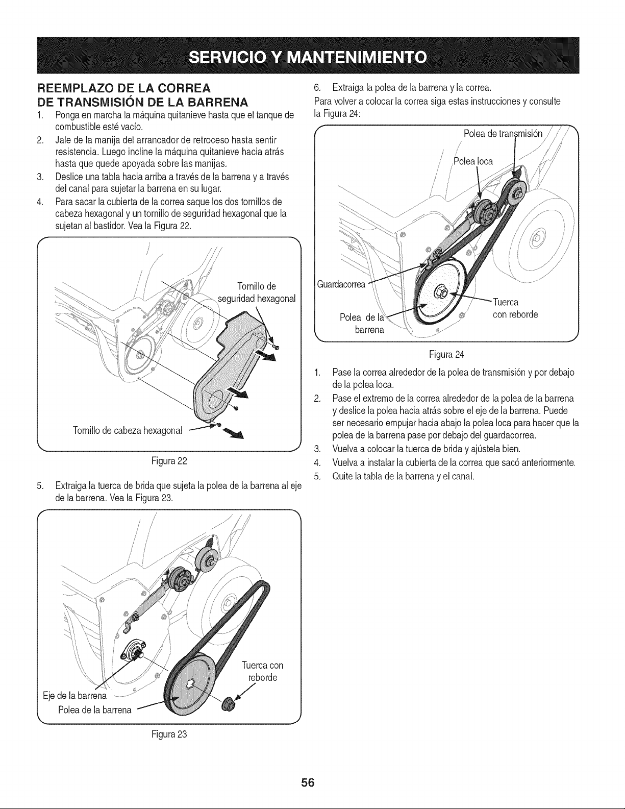
REENIPLAZO DE LA CORREA
DE TRANSMISION DE LA BARRENA
1. Pongaen marchala m&quinaquitanievehastaqueel tanquede
combustibleest_vacio.
2. Jale de la manijadel arrancadorde retrocesohasta sentir
resistencia.Luegoincline la m_.quinaquitanievehaciaatr_.s
hastaque quede apoyadasobre las manijas.
3. Desliceunatabla haciaarribaa trav_sde la barrenay a traves
delcanal parasujetarla barrenaen su lugar.
4. Parasacar la cubierta de la correasaquelos dos tornillosde
cabezahexagonaly un tornillode seguridadhexagonalque la
sujetanal bastidor.Vea la Figura22.
Tornillode
_eguridadhexagonal
.
Tornillode cabezahexagonal
J
Figura22
Extraigala tuercadebrida que sujetala polea de la barrenaal eje
de labarrena.Vea la Figura23.
6. Extraigalapoleadela barrenay la correa.
Paravolvera colocarla correasiga estasinstruccionesy consulte
la Figura24:
Poleadetransmisi6n
/ i
/ Polea Ioca
/
I !
Figura24
1. Pasela correaalrededorde la polea de transmisi6ny por debajo
de la poleaIoca.
2. Paseel extremode lacorreaalrededorde la poleade labarrena
y deslicela poleahaciaatr_.ssobreeleje de la barren& Puede
set necesarioempujarhaciaabajo la poleaIoca para hacerque la
poleade la barrenapasepor debajodel guardacorrea.
3. Vuelvaa colocar la tuercade brida y ajQstelabien.
4. Vuelvaa instalarla cubiertade la correaque sac6 anteriormente.
5. Quite la tablade la barrenay el canal.
Ejede la barrena
Poleade labarrena
Figura23
Tuercacon
reborde
J
56
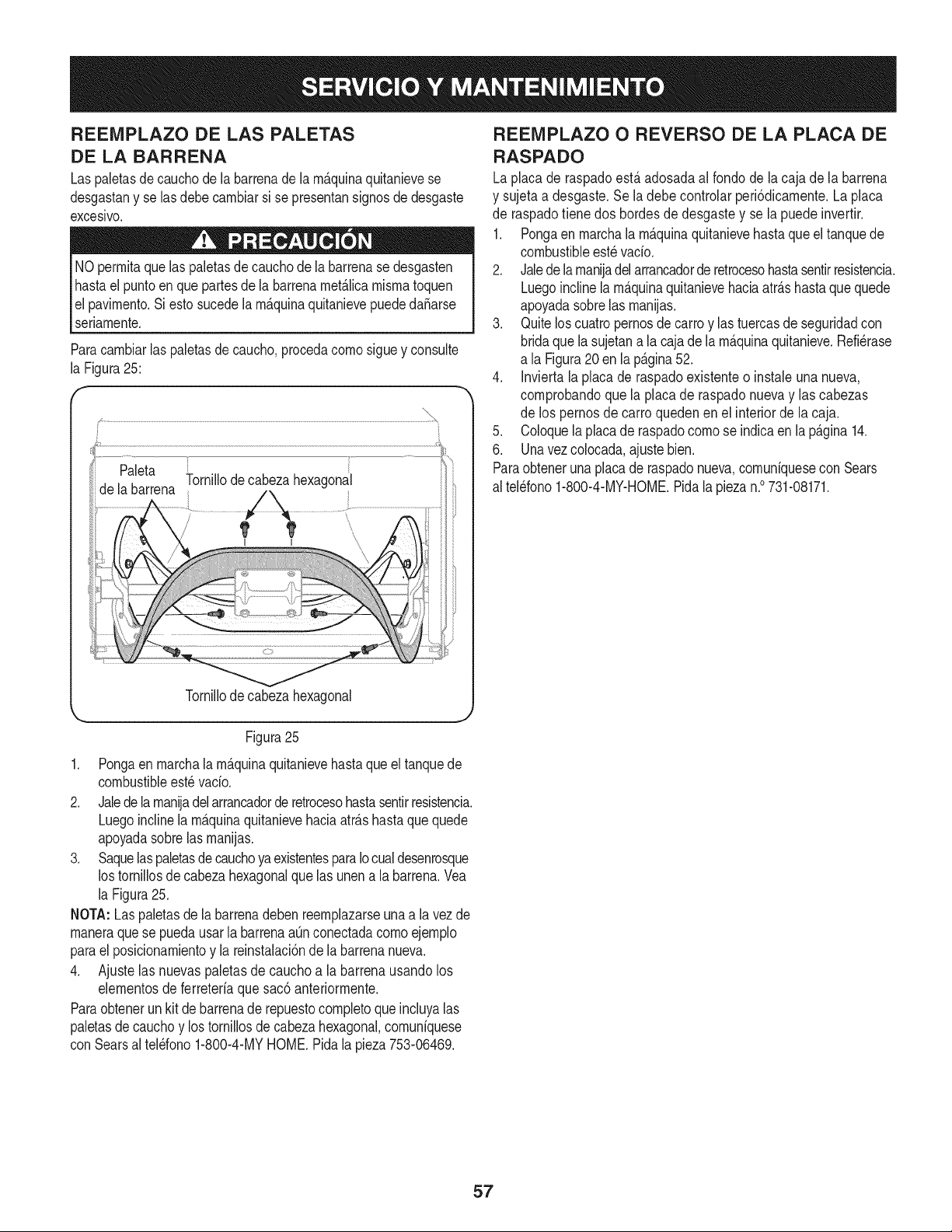
REENIPLAZO DE LAS PALETAS
DE LA BARRENA
Las paletasde cauchode labarrenade la rn&quinaquitanievese
desgastany se lasdebecarnbiarsi se presentansignosde desgaste
excesivo.
NO perrnitaquelas paletasde cauchodela barrenasedesgasten
hastael puntoenque partesde la barrenarnet_.licarnisrnatoquen
el pavirnento.Siestosucedela rn_.quinaquitanievepuededa_arse
seriarnente.
Paracarnbiarlas paletasdecaucho,procedacornosiguey consulte
la Figura25:
Tornillode cabezahexagonal
,,. j
Figura25
1. Pongaen rnarchala rn_.quinaquitanievehastaqueel tanquede
combustibleest_vado.
2. Jalede la maniadel arrancadorde retrocesohastasentirresistencia.
Luegoinclinela rn_.quinaquitanievehaciaatr_.shastaque quede
apoyadasobrelasrnanijas.
3. Saquelaspaletasde cauchoyaexistentesparaIocualdesenrosque
los tornillosde cabezahexagonalque las unena la barrena.Vea
la Figura25.
NOTA:Las paletasdela barrenadebenreernplazarseunaa la vez de
rnaneraquese puedausarla barrenaaQnconectadacornoejernplo
parael posicionarnientoy la reinstalaci6nde la barrenanueva.
4. Ajuste las nuevas paletasde cauchoa la barrenausandolos
elernentosde ferreteriaque sac6 anteriorrnente.
Paraobtenerunkit de barrenade repuestocornpletoque incluyalas
paletasdecauchoy lostornillosde cabezahexagonal,cornuniquese
con Searsal tel_fono1-800-4-MYHOME.Pida la pieza753-06469.
REEMPLAZO O REVERSO DE LA PLACA DE
RASPADO
Laplaca de raspadoest,.adosadaal fondode la caja de la barrena
y sujetaa desgaste.Se la debe controlar peri6dicarnente.La placa
de raspadotiene dos hordesde desgastey se la puedeinvertir.
1. Pongaen rnarchala rn_.quinaquitanievehastaqueel tanquede
combustibleest_vacio.
2. Jalede la rnanijadel arrancadorde retrocesohastasentirresistencia.
Luegoinclinelarn_.quinaquitanievehaciaatr_.shasta que quede
apoyadasobrelas rnanijas.
3. Quiteloscuatropernosdecarro y las tuercasde seguridadcon
bridaquela sujetana la caja de la rn_.quinaquitanieve.Refi_rase
a la Figura20en lap_.gina52.
4. Inviertala placade raspadoexistenteo instaleuna nueva,
cornprobandoque la placa de raspadonuevay las cabezas
de los pernosdecarro quedenen el interiorde la caja.
5. Coloquelaplacade raspadocornose indicaen la p_.gina14.
6. Unavezcolocada,ajustebien.
Paraobteneruna placade raspadonueva,cornuniquesecon Sears
al tel_fono1-800-4-MY-HOME.Pidala piezan.° 731-08171.
57
Si nose va a utilizarlarn_.quinaquitanievedurante30 diaso rn_.s,o si es el finalde la ternporadadenievey ya noexisteposibilidaddeque
nieve,es necesarioalrnacenarelequipo de rnaneraadecuada.Siga lasinstruccionesde alrnacenarnientoque seindicana continuaci6npara
garantizarel rendirnientorn_.xirnode la rn_.quinaquitanieveduranternuchosaSosrn_.s.
PREPARACION DEL MOTOR
Losrnotoresquesealrnacenandurantern_.sde 30 dias debenser
drenadosdecombustibleparaevitarquesedeterioreny se forrnegorna
enel sisternade combustibleo en laspiezasprincipalesdelcarburador.
Sila gasolinaensu motorse deterioraduranteelalrnacenarniento,
puederesultarnecesariorepararo reernphzarelcarburadory otros
cornponentesdel sisternade combustible.
1. Elirninetodoel combustibledel tanquehaciendofuncionarel motor
hastaquese detenga.
2. Carnbieel aceite del motor.
3. Extraigala bujiade encendidoy vierta en el cilindro
aproxirnadarnente1 onza(30 rnl)de aceitepara motorlirnpio.Tire
variasvecesdelarrancadorde retrocesoparadistribuirel aceitey
reinstalelabujia.
4. Lirnpieel exteriordel motoral elirninarla suciedady losescornbros
delas siguientes_.reas:
• Aletasde refrigeraci6n
• Filtrode adrnisi6nde aireo Areasde protecci6ndel volante/
arrancadorde retroceso
• Conexi6nde labujia
• Palancas
• Areade enlace
• Protecciones
Carburador
Culatadelmotor
No rocieel motorcon aguaparalirnpiarloporqueel aguapodria
contarninarel combustible.Sise utilizaunarnangueradejardin
o equipodelavadoa presi6ntarnbi_npuedeentraraguadentro
dela aberturadel silenciador.El agua que pasapor el silenciador
puedeingresaren el cilindro,causandodaSos.
PREPARACION DE LA M.&.QUINA QUITANIEVE
Si no seva a usar larn_.quinaquitanievedurante30 dias o rn_.s,siga
las siguientesinstruccionesincluidasa continuaci6n.
1. Alrnaceneel equipoen un _.readespejaday seca.
2. Lirnpiela rn_.quinaquitanievecon un trapo y quitela suciedad
o los residuos.
3. Si alrnacenala rn_.quinaquitanieveen un lugarrnal ventilado,
cubralas piezasrnet_.licasde la rn_.quinacon unacapa delgada
de aceiteo siliconacornoantioxidante.
5. AIrnaceneel motoren un sectorlirnpio,secoy bien ventilado,
lejosdecualquierartefactoque funcionecon unallamao luz
pilotocornohornos,calentadoresde agua o secadoresde ropa.
Evitecualquiersectorcon unmotorel_ctricoqueproduzca
chispaso donde se utilicenherrarnientasel_ctricas.
Nuncaalrnacenela rn_.quinaquitanievecon combustibleenel tanque
enun espaciocerradoo en _.reascon pocaventilaci6n,dondelos
gasesdelcombustiblepuedanalcanzarel fuego,chispaso una luz
pilotocornola que tienenalgunoshornos,calentadoresde agua,
secadoresde ropao alg_n otto dispositivoa gas.
6. Si es posible,evite sectoresde alrnacenarnientoconrnucha
hurnedad.
7. Mantengael motorniveladocuandoIo alrnacene.Lainclinaci6n
delmotorpuede resultaren fugas de combustibleo aceite.
58
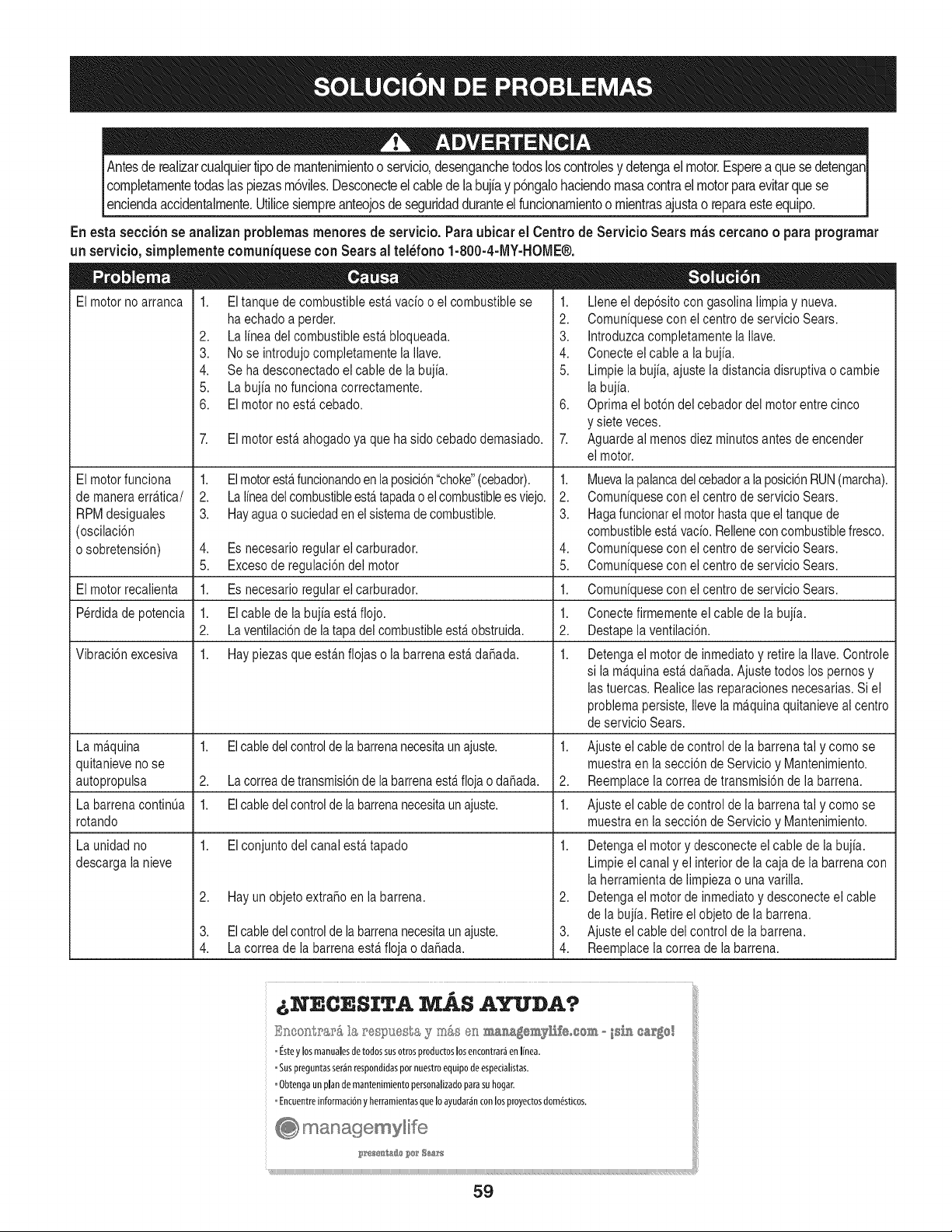
Antes de realizarcualquier tipo de mantenimientoo servicio, desenganche todos los controles y detenga el motor. Esperea que se detenganI
completamente todas las piezas m6vles. Desconecteel cable de la bujfa y p6ngalo haciendo masa contra el motor para evitar que se I
Ienc enda acc dentamente. Ut ce sempre anteojos de segurdad durante e func onam ento o m entras ajusta o repara este equ po. I
En esta secci6n se anaizan problemas menores de servicio. Para ubicar el Centro de Servicio Sears mils cercano o para programar
un servicio, simplemente comuniquese con Sears al tel_fono 1-800-4-MY-HOME®.
El motor no arranca 1. B tanque de combustible estfi vacio o el combustible se 1. Llene el dep6sito con gasolina limpia y nueva.
El motor funciona
de manera errftica/
RPM desiguales
(oscilacidn
o sobretensi6n)
Ei motor recaiienta
Perdida de potencia
Vibraci6n excesiva
ha echado a perder.
2. La lnea dei combustible estfi bloqueada.
3. No se introdujo completamente la lave.
4. Se ha desconectado el cable de la bujia.
5. La bujia nofuncionacorrectamente.
6. El motor noestfcebado.
7. El motor est£ ahogado ya que ha sido cebado demasiado.
1. Elmotorest£ funcionandoen laposici6n"choke"(cebador).
2. La linea del combustibleest£ tapadao ei combustiblees viejo.
3. Hayagua o suciedaden el sistemade combustible.
2. Comuniquesecon el centro de servicio Sears.
3. Introduzcacompletamentelallave.
4. Conecte el cable a la bujia.
5. Limpie la bujia, ajuste la distancia disruptiva o cambie
la bujia.
6. Optima el botdn del cebador del motor entre cinco
y siete veces.
4. Es necesario regular el carburador.
5. Excesoderegulaci6n dei motor
1. Es necesario regulareicarburador.
1. El cable de la bujia est£ flojo.
2. La ventiiaci6n de iatapa dei combustibleest£ obstruida.
1. Hay piezas que estfin flojas o la barrena estfi da_ada.
7. Aguarde ai menos diez minutos antes de encender
ei motor.
1. Muevalapalancadel cebadora laposici6nRUN(marcha).
2. Comuniquesecon ei centro de servicio Sears.
3. Hagafuncionar el motorhasta que el tanque de
combustibleest£ vacio. Relienecon combustiblefresco.
4. Comuniquesecon ei centro de servicio Sears.
5. Comuniquesecon ei centro de servicio Sears.
1. Comuniquesecon ei centro de servicio Sears.
1. Conecte firmementeel cable de la bujia.
2. Destapeiaventiiaci6n.
1. Detengael motor de inmediato y retire ia/ave. Controle
si la mfquina est£ da_ada. Ajuste todos los pernos y
las tuercas. Realice las reparaciones necesarias. Si el
problema persiste,iieve ia mfquina quitanieve ai centro
de servicio Sears.
La mfquina 1. Elcabledel controlde labarrenanecesita unajuste. 1.
quitanieve no se
autopropulsa 2. La correa detransmisi6n de la barrena est£ floja o da_ada. 2.
La barrena continQa 1. El cabledel control de la barrenanecesitaun ajuste. 1.
rotando
1. El co@untodel canal est£ tapado 1.
La unidad no
descarga la nieve
2. Hay un objeto extra_o en la barrena.
3. El cable del controlde la barrenanecesitaunajuste.
4. La correa de la barrena estfi floja o da_ada.
2,
3.
4.
Ajuste el cable de control de la barrena tal y como se
muestra en ia secci6n de Servicio y Mantenimiento.
Reemplace ia correa de transmisi6n de ia barrena.
Ajuste el cable de control de la barrena tal y como se
muestra en la secci6n de Servicio y Mantenimiento.
Detengael motor y desconecte el cable de la bujia.
Limpie el canal y el interior de la caja de la barrena con
la herramienta de iimpieza o unavariiia.
Detengael motor de inmediato y desconecte el cable
de la bujia. Retire el objeto de la barrena.
Ajuste el cable del control de la barrena.
Reemplace la correa de la barrena.
NECESITA MAS AYUDA? i
£k_eo_;tr_:__&I_ J'esp_J@-;_s_s5_ _),_ en ma_,a_®_y1'_£eoco_ ° isi,_ ca'_o!
=iste y losmanualesdetodossisotros productoslosencontrariIn Inea.
Suspreguntasseranrespondidaspornnestroequipodeespecialstas.
_Obtengaunplandemantenimientopersonalizadoparasuhogar.
Encuentreinformaci6ny herramientasqueIoayudar£nconlosproyectosdom_sticos.
59
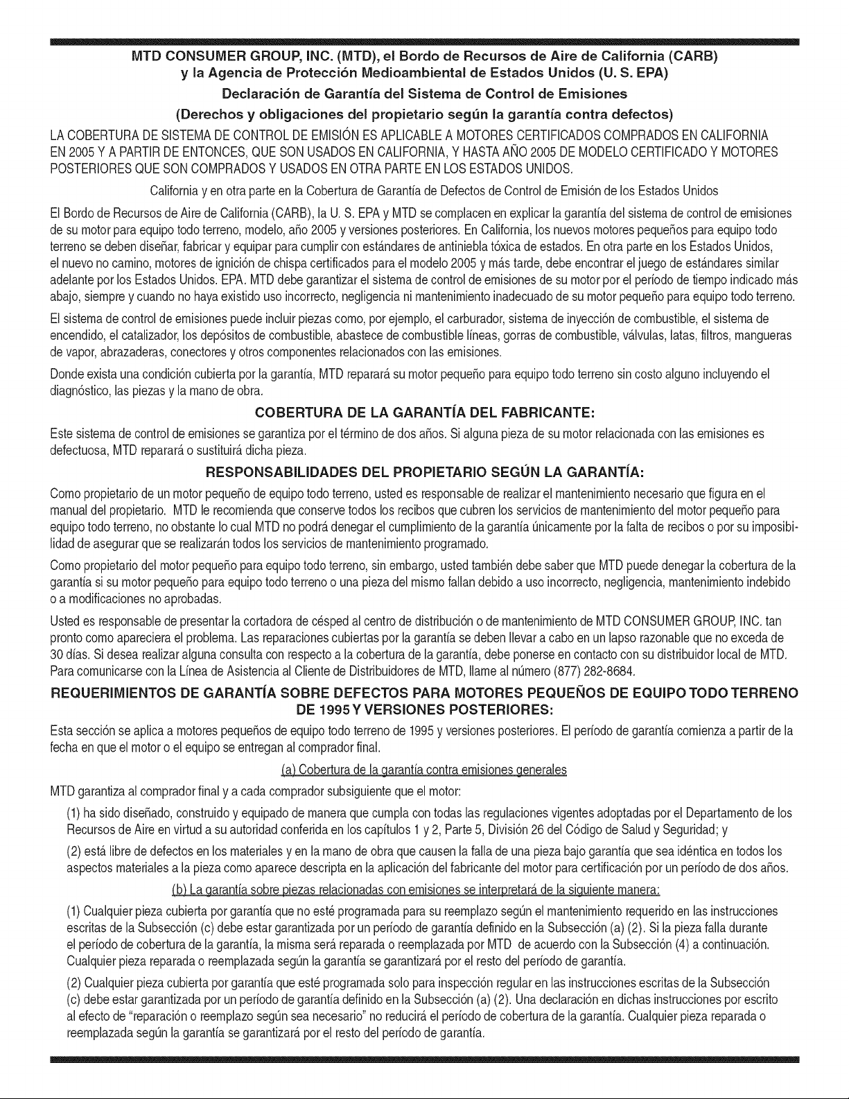
MTD CONSUMER GROUP, iNC. (MTD), el Bordo de Recursos de Aire de California (CARB)
y la Agencia de Protecci6n Medioambiental de Estados Unidos (U. S. EPA)
Declaraci6n de Garantia del Sistema de Control de Emisiones
(Derechos y obligaciones del propietario seg_n la garantia contra defectos)
LACOBERTURADESISTEMADECONTROLDEEMISIONESAPLICABLEA MOTORESCERTIFICADOSCOMPRADOSENCALIFORNIA
EN2005Y A PARTIRDE ENTONCES,QUESON USADOSEN CALIFORNIA,Y HASTAANO2005 DE MODELOCERTIFICADOY MOTORES
POSTERIORESQUESON COMPRADOSY USADOSENOTRAPARTEEN LOSESTADOSUNIDOS.
Californiayen otraparteen la Coberturade Garantiade Defectosde Controlde Emisi6nde los EstadosUnidos
El Bordode Recursosde Airede California(CARB),la U.S. EPAy MTDsecomplacenenexplicarla garantiadel sistemade controlde emisiones
de su motorparaequipotodo terreno,modelo,aSo2005y versionesposteriores.En California,los nuevosmotorespequeSospara equipotodo
terrenose debendise5ar,fabricary equiparparacumplirconest_.ndaresde antinieblat6xicade estados.En otraparteen los EstadosUnidos,
el nuevono camino,motoresde ignici6nde chispacertificadospara el modelo2005 y m_.starde,debe encontrareljuegode est_.ndaressimilar
adelantepor los EstadosUnidos.EPA.MTDdebe garantizarel sistemade controlde emisionesde su motorpor el periodode tiempoindicadom&s
abajo,siemprey cuandono hayaexistidousoincorrecto,negligenciani mantenimientoinadecuadode su motorpequeBoparaequipotodoterreno.
El sistemadecontrolde emisionespuedeincluirpiezascomo,por ejemplo,el carburador,sistemade inyecci6nde combustible,el sistemade
encendido,el catalizador,losdep6sitosde combustible,abastecede combustiblelineas, gorrasde combustible,v&lvulas,latas,filtros,mangueras
devapor,abrazaderas,conectoresy otroscomponentesrelacionadosconlas emisiones.
Dondeexistauna condici6ncubiertapor la garantia,MTDreparar&su motor pequeBoparaequipotodoterrenosincostoalguno incluyendoel
diagn6stico,laspiezasy la manode obra.
COBERTURA DE LA GARANTJA DEL FABRICANTE:
Estesistemade controlde emisionesse garantizapor el t@rminodedos a5os.Si algunapiezade su motorrelacionadacon lasemisioneses
defectuosa,MTD reparar&o sustituir&dichapieza.
RESPONSABJLIDADES DEL PROPIETARIO SEGUN LA GARANTJA:
Comopropietariode un motorpequeSode equipotodoterreno,ustedes responsablede realizarel mantenimientonecesarioquefigura enel
manualdel propietario. MTDle recomiendaqueconservetodos los recibosque cubrenlos serviciosde mantenimientodel motorpeque5opara
equipotodoterreno,noobstanteIo cual MTDno podr&denegarel cumplimientode la garantiaQnicamentepor la falta de reciboso por su imposibi-
lidadde asegurarque se realizar_.ntodoslos serviciosdemantenimientoprogramado.
Comopropietariodel motorpeque5oparaequipotodo terreno,sinembargo,ustedtambi@ndebesaberque MTDpuede denegarla coberturadela
garantiasi su motorpeque5oparaequipotodoterrenoo una piezadel mismofallandebido a usoincorrecto,negligencia,mantenimientoindebido
oa modificacionesnoaprobadas.
Ustedes responsablede presentarlacortadoradecespedal centrode distribuci6no de mantenimientode MTDCONSUMERGROUP,INC. tan
prontocomo aparecierael problem& Lasreparacionescubiertaspor la garantfasedeben Ilevara cabo en un lapsorazonableque no excedade
30dias. Si desearealizaralgunaconsultacon respectoa la coberturade la garantia,debe ponerseencontactocon su distribuidorlocalde MTD.
Paracomunicarseconla Lineade Asistenciaal Clientede Distribuidoresde MTD,Ilameal nQmero(877)282-8684.
REQUERJMJENTOS DE GARANTJA SOBRE DEFECTOS PARA MOTORES PEQUENOS DE EQUJPO TODO TERRENO
DE 1995YVERSJONES POSTERJORES:
Estasecci6nse aplicaa motorespeque5osde equipotodo terrenode 1995y versionesposteriores.El periodode garantiacomienzaa partirde la
fechaen queel motoro el equipo seentreganal compradorfinal.
(a)Coberturade la garantiacontraemisionesgenerales
MTDgarantizaal compradorfinaly acada compradorsubsiguientequeel motor:
(1)hasido diseSado,construidoy equipadode maneraque cumplacontodas las regulacionesvigentesadoptadaspor el Departamentode los
RecursosdeAire en virtud a suautoridadconferidaen los capitulos1 y 2, Parte5, Divisi6n26 del C6digode Saludy Seguridad;y
(2)est,. librede defectosen los materialesy en la manode obraquecausenla falla de una piezabajo garantiaque seaid@nticaen todos los
aspectosmaterialesa la piezacomo aparecedescriptaen la aplicaci6ndel fabricantedel motorpara certificaci6npor unperiododedos a5os.
Lb/Lagarantiasobre piezasrelacJonadasconemisJonesse interpretar_,de la sJguientemanera:
(1)Cualquierpiezacubiertapor garantiaque no est@programadapara su reemplazosegQnel mantenimientorequeridoen las instrucciones
escritasdela Subsecci6n(c) debeestar garantizadapor un periodode garantiadefinidoen la Subsecci6n(a) (2). Si la piezafalladurante
el periododecoberturade la garantia,la mismaser_.reparadao reemplazadapor MTD de acuerdocon la Subsecci6n(4) a continuaci6n.
Cualquierpiezareparadao reemplazadasegQnla garantiasegarantizarB,por el resto del periodode garantia.
(2) Cualquierpiezacubiertaporgarantiaque est@programadasolopara inspecci6nregularen las instruccionesescritasde la Subsecci6n
(c) debeestargarantizadaporun periodode garantiadefinidoen la Subsecci6n(a) (2). Unadeclaraci6nen dichasinstruccionespor escrito
alefectode "reparaci6no reemplazosegQnseanecesario"no reducir_,el periodode coberturade la garantia.Cualquierpiezareparadao
reemplazadasegQnla garantiase garantizar_,porel restodel periodode garantia.
(3) Cualquierpiezagarantizadaqueest_prograrnadaparareernplazosegQnelrnantenirnientorequeridodeconforrnidadconlasinstruc-
clonesescritasdelaSubsecci6n(c)segarantizaporelperiododetiernpoanterioralaprirnerafechadereernplazoprograrnadaparaesa
pieza.Silapiezafallaantesdelprimerreernplazoprogramatic,larnisrnaser_.reparadaoreernplazadaporMTDdeacuerdoconlaSubsecci6n
(4)acontinuaci6n.Cualquierpiezareparadaoreernplazadabajogaranfiasegarantizar_,porelrestodelperiodoanterioralprimerreernplazo
programaticpuntualparaesapieza.
(4)Lareparaci6noelreernplazodecualquierpiezagarantizadadeconforrnidadconlasdisposicionesdelagaranfiaqueaquiseestipulase
deberealizarenuncentrodegaranfiasincostoalgunoparaelpropietario.
(5)SinperjuiciodelasdisposicionesdelaSubsecci6n(4)anterior,losserviciosoreparacionescubiertosporlagaranfiadebensersurnin-
istradosportodosloscentrosdedistribuci6ndeMTDquetenganlafranquiciapararealizarreparacionesyrnantenirnientoalosrnotoresen
cuesti6n.
(6)ElpropietarionodebeafrontarningQncargoparatrabajosdediagn6sticoqueIlevena laconclusi6ndequeunapiezabajogaranfiapresenta
efectivarnentedefectos,siernpreycuandodichodiagn6sticoseaIlevadoacaboenuncentrocubiertoporlagarantia.
(7)ElfabricantedelmotoresresponsablepordaSoscausadosaotroscornponentesdernotoresderivadosdelafallabajogaranfiadecualquier
piezagarantizada.
(8)DurantetodoelperiododegaranfiadelmotordefinidoenlaSubsecci6n(a)(2),MTDrnantendr_,unsurninistrodepiezascubiertaspor
garantiasuficienteparasatisfacerladernandaesperadaparatalespiezas.
(9)Cualquierpiezadereernplazosepodr_,usarparaelcurnplirnientodelrnantenirnientooreparacionesbajogaranfia,ysesurninistrar_,sin
cargoalpropietario.Dichousonoreducir_,lasobligacionesdegarantiadeMTD.
(10)Nosepodr_.nusarpiezasadicionalesnirnodificadasquenoest_nexentasdeacuerdoconelDepartarnentodelosRecursosdelAire(Air
ResourcesBoard).Elusodepiezasadicionalesornodificadasnoexentasser_.causasuficienteparaanularunreclarnobajogaranfiarealizado
deacuerdoconestearticulo.Elfabricantedelmotornotendr_,responsabilidad,enconforrnidadconestearticulo,degarantizarfallasdepiezas
garantizadasquefuerencausadasporelusodeunapiezanoexentaadicionalornodificada.
.(c)MTDincluir_,una copiade la siguientelistade piezasbajogarantiacontraernisionescon cadanuevomotor,utilizandolas partesde la lista
a_plicablesal motor.
(1)Sisternadernedici6nde combustible
• Sisternade rnejoraparainicioenfrio (cebadosuave)
• Carburadory cornponentesinternos
• Bornbade combustible
• Dep6sitodecombustible
(2) Sisternadeinducci6nde aire
• Filtrode aire
• Colectordeentrada
(3) Sisternadeencendido
• Bujia(s)
• Sisternadeencendidopor magneto
(4)Sisternadeescape
• Catalizador
• SAI (v_Jvulade CaSa)
(5) Cornponentesvariosutilizadosen el sisternaanterior
• V_Jvulase interruptoresde vado, ternperatura,posici6nsensiblesal tiernpo
• Conectoresy rnontajes
(6)Controlde Evaporative
• Manguerade CombustiblecertificadaparaARB evaporativeernisi6nde 2006.
• Abrazaderasde Manguerade Combustible
• Gorrade combustibleatada
• Latade carb6n
• Lineasde vapor
GD0C-100174Rev.B
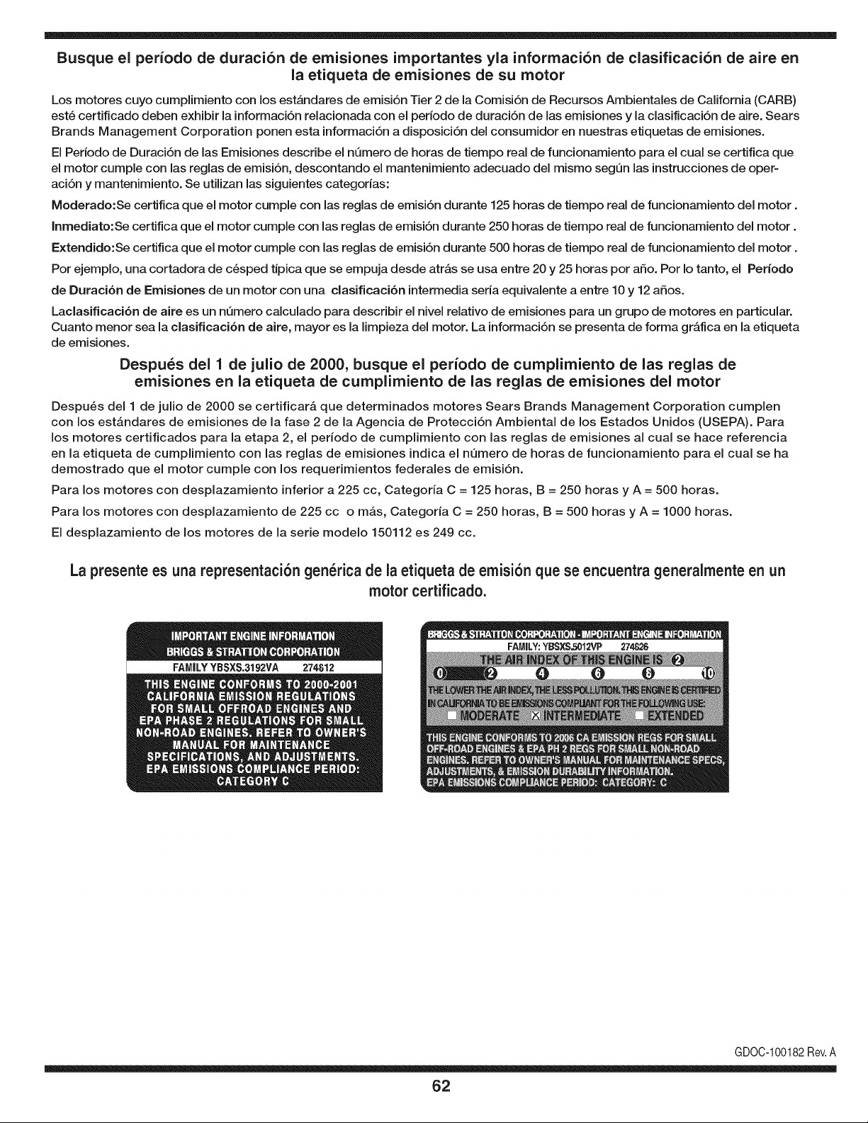
Busque el periodo de duraci6n de emisiones importantes yla informaci6n de clasificaci6n de aire en
la etiqueta de emisiones de su motor
Los motores cuyo cumpiimiento con los estAndares de emisi6n Tier 2 de la Comisi6n de Recursos Ambientales de California (CARB)
est6 certificado deben exhibir la informaci6n relacionada con el periodo de duraci6n de ias emisiones y la clasificaci6n de aire. Sears
Brands Management Corporation ponen esta informaci6n a disposici6n del consumidor en nuestras etiquetas de emisiones.
Ei Periodo de Duraci6n de las Emisiones describe el nQmero de horas de tiempo real de funcionamiento para el cuai se certifica que
el motor cumpie con ias reglas de emisi6n, descontando el mantenimiento adecuado del mismo segQn las instrucciones de oper-
aci6n y mantenimiento. Se utilizan las siguientes categonas:
Moderado:Se certifica que el motor cumpie con las reglas de emisi6n durante 125 horas de tiempo real de funcionamiento del motor.
Inmediato:Se certifica que el motor cumpie con las reglas de emisi6n durante 250 horas de tiempo real de funcionamiento del motor.
Extendido:Se certifica que el motor cumpie con las reglas de emisi6n durante 500 horas de tiempo real de funcionamiento del motor.
Por ejemplo, una cortadora de c6sped tJpica que se empuja desde arras se usa entre 20 y 25 horas por aSo. Por Io tanto, el Periodo
de Duraci6n de Emisiones de un motor con una clasificaci6n intermedia sena equivaiente a entre 10 y 12 aSos.
Laciasificaci6n de aire es un nQmero calculado para describir el nivel relativo de emisiones para un grupo de motores en particular.
Cuanto menor sea la clasificaci6n de aire, mayor es la limpieza del motor. La informaci6n se presenta de forma grAfica en la etiqueta
de emisiones.
Despu_s del 1 de julio de 2000, busque el periodo de cumplimiento de las reglas de
emisiones en la etiqueta de cumplimiento de las reglas de emisiones del motor
Despu6s del 1 de julio de 2000 se certificarA que determinados motores Sears Brands Management Corporation cumplen
con los estAndares de emisiones de la fase 2 de la Agencia de Protecci6n Ambientai de los Estados Unidos (USEPA). Para
los motores certificados para la etapa 2, el periodo de cumplimiento con ias reglas de emisiones al cual se hace referencia
en la etiqueta de cumplimiento con las reglas de emisiones indica el nQmero de horas de funcionamiento para el cual se ha
demostrado que el motor cumple con los requerimientos federales de emisi6n.
Para los motores con desplazamiento inferior a 225 cc, Categoria C = 125 horas, B = 250 horas y A = 500 horas.
Para los motores con desplazamiento de 225 cc o mAs, Categoria C = 250 horas, B = 500 horas y A = 1000 horas.
El desplazamiento de los motores de la serie modelo 150112 es 249 cc.
La presente es una representaci6n gen_rica de la etiqueta de emisi6n que se encuentra generaimente en un
motor certificado.
FAMILYYBSXS.3192VA 274812
GDOC-100182Rev.A
62
Felicitaciones por haber realizado una adquisici6n inteligente. El producto Craftsman® que ha
adquirido esta diseSado y fabricado para brindar muchos aSos de funcionamiento confiable. Pero
como todos los productos a veces puede requerir de reparaciones. Es en ese momento cuando el
disponer de un Acuerdo de protecci6n para reparaciones le puede ahorrar dinero y problemas.
A continuaci6n se detallan los puntos incluidos en el Acuerdo:
[] Servicio experto prestadopor nuestros 10,000 especialistas en reparaciones profesionales
[] Servicio ilirnitado sin cargo para las piezas y la mano de obra en todas las reparacionescubiertas
[] Reernplazo del producto hasta 1500 d61aressi no es posible reparar el producto cubierto
[] Descuento de 25% del precio normal del servicio y de las piezas relacionadas con el mismo que no esten cubiertas
por el acuerdo; ademas, 25% del precio normal de laverificaci6n de mantenimientopreventivo
[] Ayuda r_pida pot tel_fono - Io IlamamosResoluci6n RApida- el apoyo telef6nico de un Chamusca al representante.
Piense en nosotros como el manual "de un dueSohablador."
Una vez adquirido el Acuerdo, puede programar el servicio con tan s61orealizar una Ilamadatelef6nica. Puede Ilamar en
cualquier momento del dia o de la noche o programar un servicio en linea.
ElAcuerdo de Protecci6nde Reparaci6nes una compra sin riesgo. Si usted anula por alguna raz6n duranteel periodo de
garantia de producto, proporcionaremos un reembolso Ileno.O, un reembolso prorrateado en cualquier momento despues
del periodo de garantia de producto expira, iAdquiera hoy su acuerdode protecci6n para reparaciones!
Se aplican determinadas limitaciones y exclusiones. Para obtener informaciTn adicional y precios en los Estados
Unidos Ilame al 1-800-827-6655.
El *Coverage en Canad_ivaria en algunos articulos. Para detalles Ilenos la Ilamada Chamusca Canad_ien 1-800-
361-8885.
Servicio de instalaci6n de Sears
Si desea solicitar la instalaci6n profesional de Sears de aparatos domesticos, dispositivos paraabrir portones, calentado-
res de agua y otros articulos domesticos importantes, en los Estados Unidos o Canada flame al 1-800-4-MY-HOME®.
63

Your Home
For troubleshooting, product manuals and expert advice:
managernylife
www.managemylife.com
For repair - in your home - of all major brand appliances,
lawn and garden equipment, or heating and cooling systems,
no matter who made it, no matter who sold it!
For the replacement parts, accessories and
owner's manuals that you need to do-it-yourself.
For Sears professional installation of home appliances
and items like garage door openers and water heaters.
1-800-4-MY-HOME ® (1-800-469-4663)
Call anytime, day or night (U.S.A. and Canada)
www.sears.com www.sears.ca
Our Home
For repair of carry-in items like vacuums, lawn equipment,
and electronics, call anytime for the location of your nearest
Sears Parts & Repair Service Center
1-800-488-1222 (U.S.A.) 1-800-469-4663 (Canada)
www.sears.com www.sears.ca
To purchase a protection agreement on a product serviced by Sears:
1-800-827-6655 (U.S.A.) 1-800-361-6665 (Canada)
Para pedir servicio de reparaci6n
a domicilio, y para ordenar piezas:
1-888-SU-HOGAR ®
(1-888-784-6427)
www.sears.com
Au Canada pour service en frangais:
1-800-LE-FOYER Mc
(1-800-533-6937)
www.sears.ca
® Registered Trademark / TMTrademark of KCD IP, LLC in the United States, or Sears Brands, LLC in other countries
® Marca Registrada ! TMMarca de Fabrica de KCD IP, LLC en Estados Unidos, o Sears Brands, LLC in otros paises
MCMarque de commerce ! MDMarque deposee de Sears Brands, LLC


