Loading ...
Loading ...
Loading ...
VC Series Manual 17
Isolaon Valves and Pressure Relief Valve
Pressure Relief Valve (PRV) Installaon Instrucons:
The PRV must be connected to the 3/4” threaded port on the HOT (RED) water service valve (will be adjacent to
or above the shut o, never below). Installaon must maintain a ¾” port size with no shut o valve or line
restricon in-between the appliance and the PRV. The discharge line from the PRV should pitch downward and
terminate 6” above drains where discharge will be clearly visible. The discharge end of the line shall be plain
(unthreaded) and a minimum of ¾” in diameter. The discharge line material must be suitable for water at least
180° Fahrenheit. No valve of any type may be installed in the discharge line of the pressure relief valve.
Pressure Relief Valve Maintenance:
For proper care of this approved pressure relief valve, it is recommended that the valve is manually operated
once a year. In doing so, it will be necessary to take precauons with regard to the discharge of potenally
scalding hot water under pressure. Ensure discharge water has a safe place to ow. Contact with your body or
other property may cause damage or harm.
Please note that only the PRV in this package is cered by CSA Internaonal as an approved item.
The isolaon valves provide the ability to isolate the water heater from the structure’s plumbing and allow quick
access to ush the heat exchanger. Check with local codes to determine if a pressure and temperature relief
valve is required. The included valves meet American Naonal Standard (ANSI Z21.10.3) / Canadian Standard
(CSA 4.3) and are ANSI/NSF 61 approved for potable water.
Isolaon Valves Installaon Instrucons:
1. Wrap the threaded end of the approved pressure relief valve with a minimum of 5 wraps of Teon® tape.
2. Install the pressure relief valve to the 3/4” threaded port on the HOT (RED) water service valve (will be
adjacent to or above the cut o, never below). See Pressure Relief Valve Secon for proper installaon
requirements.
3. Posion the Hot Isolaon Valve (Red) below the Hot Outlet side of the water heater.
4. Hand ghten the Swivel Nut of the Hot Isolaon Valve (Red) to the Hot Outlet side of the water heater.
5. Rotate the Drain Valve to an accessible posion. With a wrench, ghten the Swivel Nut to the water heater.
6. Repeat steps 3-5 for the Cold Isolaon Valve (Blue).
7. Connect the Cold Isolaon Valve (Blue) to the Cold Water Supply Line.
8. Connect the Hot Isolaon Valve (Red) to the Hot Water Supply Line.
9. Ensure that both Drain Valves are in the closed posion before turning on water supply.
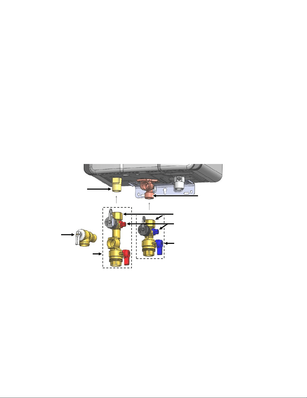
Cold Inlet
Swivel Nut (Integrated Gasket)
Drain Valve
Cold Isolaon Valve
(Blue)
Hot Isolaon Valve
(Red)
Hot Outlet
Pressure
Relief Valve
Loading ...
Loading ...
Loading ...