Loading ...
Pacic Accessory Corporation
®
| Ph. 866-931-8021 | [email protected]
©2015 Pacic Accessory Corporation
www.pac-audio.com
Rev. 051915
Page 2
BCI-CH21
Navigation Unlock & Reverse Camera Input
Interface for Chrysler/Dodge/Jeep/Ram Vehicles
Pacific Accessory Corporation
Installation Steps
8. If you wish to use the forced reverse camera feature on any of the vehicles listed in the
chart to the right, and the vehicle is equipped with a factory reverse camera, you may
need to use the BCI-CH21’s red camera turn on wire to power up the factory reverse
camera.To do this a wire must be ran from the BCI-CH21 harness to the factory
power wire for the reverse camera. The location of this wire will vary depending upon
which vehicle you are installing the BCI-CH21 into. Please see below for the different
locations. Please Note: If the customer does not wish to use the forced reverse
camera, or the reverse camera image is present when using forced reverse camera,
you do not have to locate and connect this wire.
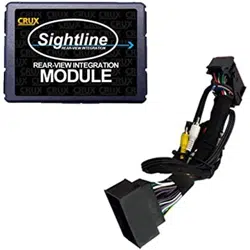
1. You will need to locate the reverse camera wire in the rear harness located above the rear door trim panel (Fig A).
2. The reverse camera wire is the white/green wire (test with a DMM to verify 12v when the vehicle is shifted into reverse) (Fig B).
3. Connect the red camera turn on wire from the BCI-CH21 to the white/green wire using a diode (Fig C). The diode is needed to prevent the
reverse lights from coming on when the reverse camera is activated.
4. Verify that the reverse lights do not come on when the reverse camera unlock feature is being used.
Reverse
Camera
Red Camera Activation Wire
Wht/Grn Camera Wire
Connect Diode
Here
Connect Red Wire
From BCI-CH21 Here
Fig CFig B
Fig A
Make Model Year
Dodge Caravan 2010‐2015
Dodge Journey 2009‐2010
Chrysler Town&Country 2008‐2015
Volkswagen Routan 2009‐2013
PowerUpFactoryReverseCamera
9. If you are adding an additional A/V input: Connect the A/V outputs from the source to the A/V inputs on the radio side of the BCI-CH21-
AUX harness. If you have more than one source, the AVS21 must be used (sold seperately).
10. Connect the factory harness(es) into the female connectors on the BCI-CH21 harnesses.
11. Turn the ignition to the on position
12. Plug the black micro-t 24-pin connector on the BCI-CH21 harness into the BCI-CH21.
13. Both LEDs will blink green while the module is initializing. Once initialized, one LED will begin to blink green. If the LED blinks amber or red,
there is a problem with the data connection to the factory radio. In this case please refer to the troubleshooting section on page 4.
14. Turn the vehicle off and wait 5 minutes. After 5 minutes, turn vehicle back on and test BCI operation (see operation section on page 3).
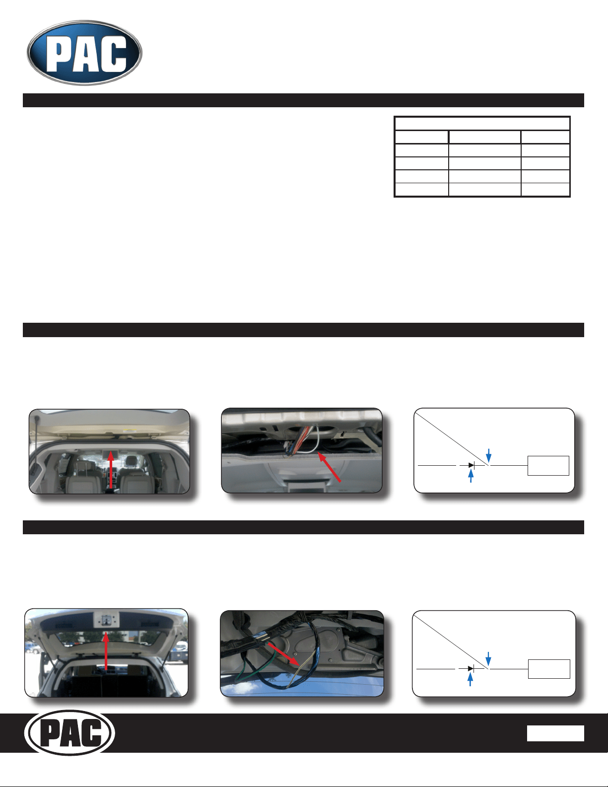
1. You will need to locate the reverse camera wire in the reverse camera harness located in the liftgate. (Fig A).
2. The reverse camera wire is the white/green wire (test with a DMM to verify 12v when the vehicle is shifted into reverse) (Fig B).
3. Connect the red camera turn on wire from the BCI-CH21 to the white/green wire using a diode (Fig C). The diode is needed to prevent the
reverse lights from coming on when the reverse camera is activated.
4. Verify that the reverse lights do not come on when the reverse camera unlock feature is being used.
Fig C
Reverse
Camera
Red Camera Activation Wire
Wht/Grn Camera Wire
Connect Diode
Here
Connect Red Wire
From BCI-CH21 Here
Fig A
Fig B
Reverse Camera Wire Location - Caravan/Town & Country/Routan
Reverse Camera Wire Location - Journey
Loading ...
Loading ...