Loading ...
Loading ...
Loading ...
4. Road test tractorfor proper stopping
distance as stated above. Readjust if
necessary. If stoppingdistance isstill
greater than six (6) feet in highest gear,
further maintenance is necessary.
Contact a Sears or other qualified
service center.
Wlth Perking Brake "Engaged"
m Nut
._OOperating
Arm
DoNottouchthis nut. Iffurtherbrake
adjustmentis necessarycontacta Searsor
otherqualifiedservicecenter.
TO REPLACE MOTION DRIVE BELT
Park the tractor on level surface. Engage
parkingbrake. For assistance, there isa
belt installation guide decal on bottom
side of left footrest.
1. Remove mower (Sea "TO REMOVE
MOWER" in thissection of this
manual.)
2. Disconnect clutch wire harness.
3. Remove clutch Iocator.
4. Remove bolt from stationary idler and
clutching idler.
5. Pull belt slack toward rear of tractor.
Carefully remove belt upwards from
transmission input pulley and over
cooling fan blades.
6. Pull belt toward front oftractor and
remove downwards from around
electric clutch.
7. Install new belt by reversing above
procedure.
Electric_ _
Clutch
Clutching_
Idler
Stationaryj
Idler
Transmission
InputPulley-"
Clutch
--Locator
Clutch
Wire Harness
TRANSMISSION REMOVAL/REPLACE-
MENT
Should your transmission require
removal for service or replacement, it
should be purged after reinstallationand
before operating the tractor. See "PURGE
TRANSMISSION" in the Operation
section of this manual.
TO ADJUST STEERING WHEEL ALIGN-
MENT
If steering wheel crossbars are not
horizontal (left to right) when wheels are
positioned straight forward, remove
steering wheel and reassemble per
instructionsin the Assembly section of
this manual.
FRONT WHEEL TOE-IN/CAMBER
The front wheel toe-in and camber are
notadjustable on your tractor. If damage
has occurred to affect the front wheel toe-
in or camber, contact your nearest Sears
or other qualified service center.
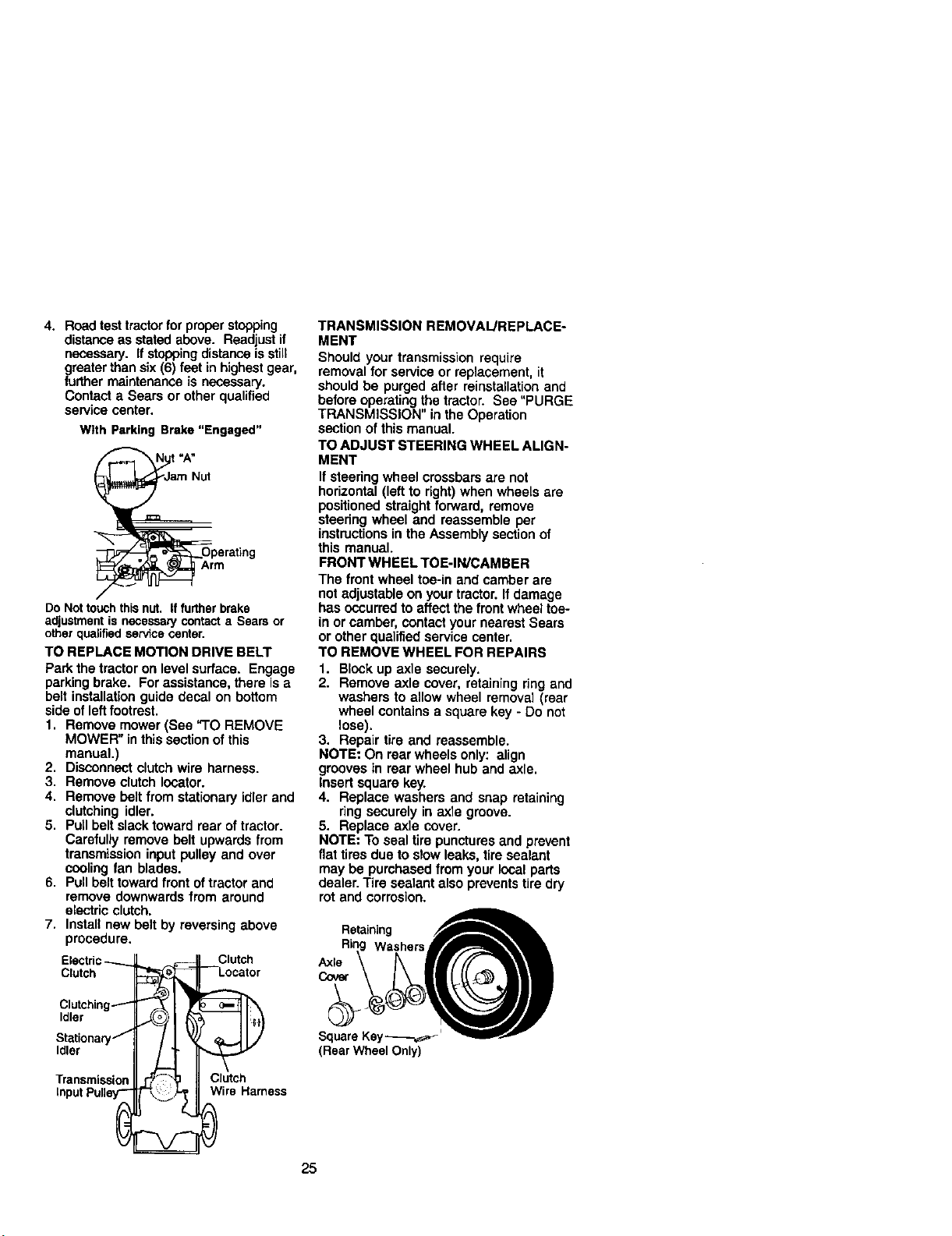
TO REMOVE WHEEL FOR REPAIRS
1. Block up axle securely.
2. Remove axle cover, retaining ring and
washers to allow wheel removal (rear
wheel contains a square key - Do not
lose).
3. Repair tire and reassemble.
NOTE: On rear wheels only: align
grooves in rear wheel hub and axle.
Insert square key.
4. Replace washers and snap retaining
ring securely in axle groove.
5. Replace axle cover.
NOTE: To seal tire punctures and prevent
flat tires due to slow leaks, tire sealant
may be purchased from your local parts
dealer. Tire sealant also prevents tire dry
rot and corrosion.
Retaining
Washers
Axle
Cover
Square Key_,_"
(Rear Wheel Only)
25
Loading ...
Loading ...
Loading ...