
Owner's Manual
ICRRFTSMRW
20.0 HP
ELECTRIC START
48" MOWER
AUTOMATIC
LAWN TRACTOR
Model No.
917.272243
• Safety
• Assembly
• Operation
• Maintenance
• Repair Parts
CAUTION:
Read and follow all
Safety Rules and Instructions
before operating this equip-
ment.
For answers to your questions
about this product, Call:
1-800-659-5917
Sears Craftsman Help Line
5 am - 5 pro, Mon - Sat
Sears, Roebuck and Co., Hoffman Estates, IL 60179
Visit our Craftsman website: www.sears.comJcraftsman
Warranty ............................................... 2
Safety Rules ......................................... 3
Product Specifications .......................... 6
Assembly .............................................. 8
Operation ............................................ 12
Maintenance Schedule ...................... 18
Maintenance ....................................... 18
Service and Adjustments .................... 22
Storage ............................................... 29
Troubleshooting ................................. 30
Repair Parts ........................................ 34
Parts Ordering ..................... Back Cover
LIMITED TWOYEAR WARRANTY ON CRAFTSMAN RIDING EQUIPMENT PARTS
For two (2) years from the date of purchase, if thisCraftsman Riding Equipment is
maintained, lubricated and tuned up according to the instructions in the owner's
manual, Sears will repair or replace, free of charge, any parts found to be defective in
material or workmanship. Warranty service is available free of charge byreturning
your Craftsman riding equipment to your nearest Sears Service Center. In-home
warranty service is available but a trip charge will apply. This warranty applies only
while thisproduct is in the United States.
This Warranty does not cover:
• Expendable items which become worn during normal use, such as blades, spark
plugs, air cleaners, belts and oil filters.
• Tire replacement or repair caused by punctures from outside objects, such as nails,
thorns, stumps, or glass.
• Repairs necessary because of operator abuse, including but not limited to, damage
caused by towing objects beyond the capability of the riding equipment, impacting
objects that bend the frame or crankshaft, or over speeding the engine.
• Repairs necessary because of operator negligence, including but not limited to,
electrical and mechanical damage caused by improper storage, failura to use the
proper grade and amount of engine oil, failure to keep the deck clear of flammable
debds, or the failure to maintain the equipment according to the instructions
contained in the owner's manual.
• Engine (fuel system) cleaning or repairs caused by fuel determined to be contami-
nated or oxidized (stale). In general, fuel should be used within thirty (30) days of its
purchase date.
• Riding equipment used for commercial or rental purposes. A product is "used for
commercial purpose" if is used for any purpose other than single family household
dwellings or in usage where profit is made.
LIMITED 90 DAYWARRANTY ON BA'I-rERY
For ninety (90) days from date of pumhase, if any battery included with this riding
equipment proves defective in matedal or workmanship and our testing determines
the battery will not hold a charge, Sears will replace the battery at no charge. War-
rarity service is available free of charge by returning your Craftsman dding equipment
to your nearest Sears Service Center. In-home warranty service isavailable but a tdp
charge will apply.This warranty applies only while this product is in the United States.
TO LOCATE THE NEAREST SEARS SERVICE CENTER OR TO SCHEDULE IN-
HOME WARRANTY SERVICE, SIMPLY CONTACT SEARS AT1-800-4-MY-HOME
This Warranty gives you specific legal rights, and you may also have other rights
which may vary from state to state.
Sears, Roebuck and Co., [3/817 WA, Hoffman Estates, IL 60179
2
IMPORTANT: This cuttng machine s capab e of amputating hands and feet and
throwingobjects. Failure to observe the foUowing safety instructionscould result in
serious iniury or death.
I. GENERAL OPERATION
• Read, understand, and loitow all
instructionsin the manual and on the
machine beforestarting.
• Only allow responsibleadults, who are
familiar withthe instructions,to operate
the machine.
• Clear the area ofobjectssuch as rocks,
toys, wire, etc., whichcould be picked
up and thrownbythe blade.
• Be sure the area is clear of other people
before mowing. Stop machine if anyone
enters the area.
,_ Never carry passengers.
Do not mow in reverse unless absolutely
necessary. Always look down and
behind before and while backing.
• Be aware of the mower discharge
directionand do notpointit at anyone.
Do not operate the mower withouteither
the entire grasscatcheror the guard in
place.
• Slow down before fuming.
• Never leave a runningmachine
unattended. Alwaysturn off blades, set
parkingbrake, stopengine, and remove
keys before dismounting.
• Turn off blades when not mowing.
• Stop engine before removing grass
catcher or uncloggingchute.
• Mow only in daylightor good artificial
light.
• Do notoperate the machine while under
the influence of alcoholor drugs.
• Watch fortrafficwhen operating near or
crossing roadways.
• Use extra care when loading or unload-
ingthe machineinto a trailer or truck.
• Data indicates that operators, age 60
years and above, are involved in a large
percentage of riding mower-related
injuries. These operators should
evaluate their abilityto operate the riding
mower safelyenough to protect them-
selves and others from seriousinjury.
• Keep machine free of grass, leaves or
other debds build-up which can touch
hot exhaust/ engine pads and bum, Do
notallow the mower deck to plow leaves
or other debris whichcan cauSe build-
up to occur. Clean any oil or fuel
spillagebefore operating or storing the
machine. Allow machine to coolbefore
storage.
II. SLOPE OPERATION
Slopes are a major factor related to loss-of-
control and tipover accidents,which can re.
suit in severe injury or death. All slopes
require extra caution. If you cannotback up
the slope or if you feel uneasy on it, do not
mow it.
DO:
* Mow up and down slopes,notacross.
Remove obstacles suchas recks, tree
limbs,etc.
Watch tot holes, ruts, or bumps. Uneven
terrain couldoverturnthe machine. Taft
grass can hide obstack_s.
Use slowspeed. Choose a low gear so
thatyouwill nothave to stopor shift
while on the slope.
Follow the manufacturer's recommenda-
tions for wheel weightsor counter-
weightsto improvestability.
Use extracare withgrasscatchers or
other attachments. These can change
the stability of the machine.
Keep all movement on the slopes slow
and gradual Do not make sudden
changes in speed or direction.
Avoid startingor stoppingon a slope, If
tires lose traction, disengage the blades
and proceed slowly straight clownthe
slope.
DO NOT:
• Do not turnon slopesunless eacessa_J,
and then, turn slowly and gradually
downhill, if possible.
• Do notmow near drop-offs,ditches,or
embankments. The mower could
suddenly turnover if a wheef is over the
edge of a clifforditch, or if an edge
caves in,
• Do not mow on wet grass.Reduced
traction could cause sliding.
• Do not try to stabilizethe machine by
puttingyourfoot on the ground.
• Do notuse grass catcher on steep
slopes.
3
III. CHILDREN •
Tragic accidents can occur if the operator area.
is not alert to the presence of children. •
Children are often attracted to the
machine and the mowing activity. Never
assume that children will remain where
you lastsaw them.
• Keep children out of the mowing area
and under the watchful care of another
responsible adult.
• Be alert and turn machine off ifchildren
enter the area.
• Before and when backing, look behind
and down for small children.
• Never carry children. They may falloff
and be seriously injured or interfere
with safe machine operation.
• Never allow children to operate the
machine.
• Use extra care when approaching bl_ed
comers, shrubs, trees, or other objects
that may obscure vision.
IV. SERVICE
• Use extra care in handling gasoline
and other fuels. They are flammable
and vapors are explosive.
-Use only an approved container.
-Never remove gas cap or add fuel
with the engine running. Allow
engine to cool before refueling. Do
notsmoke.
-Never refuel the machine in6oors.
-Never store the machine or fuel
container inside where there is an
open flame, such as a water heater.
Never run a machine inside a closed
Keep nuts and bolts, especially blade
attachment bolts, tight and keep
equipmentin good condition.
• Never tamper with safety devices.
Check their proper operation regulady.
• Keep machine tree ol grass, leaves, or
other debris build-up. Clean oil or fuel
spillage. Allow machine to cool before
atodng.
• Stop and inspect the equipment if you
strike an object. Repair, il necessary,
before restarting.
• Never make adjustments or repairs
with the engine running.
• Grass catcher componentsare subject
to wear, damage, and deterioration,
which could expose moving parts or
allow obiects to be thrown. Frequently
check components and replace with
manufacturer's recommended parts,
when necessary.
• Mower blades are sharp and can cut.
Wrap the blade(s) or wear gloves, and
use extra caution when servicing them.
• Check brake operation frequently.
Adjust and service as required.
• Be sure the area isclear of other
people before mowing. Stop machine if
anyone enters the area.
• Never carry passengers or children
even with the blades off.
• Do not mow in reverse unless abso-
lutely necessary. Always look down
and behind before and while backing.
• Never carry children. They may fall off
and be seriously injured or interfere
with safe machine operation.
• Keep children out of the mowing area
and under the watchful care of another
responsible adult,
• Be alert and turn machine off if children
enter the area.
• Before and when backing, look behind
and down for small children.
• MOWup and down slopes (15° Max),
notacross.
• Remove obstacles such as rocks, tree
limbs, etc.
• Watch for holes, ruts, or bumps.
Uneven terrain ccuid overturn the
machine. Tall grass can hide obstacles.
4
• Use slow speed. Choose a low gear so
that you willnot have to stop or shift
while on the slope.
• Avoid starting or stoppingon a slope. If
tires lose traction, disengage the
blades and proceed slowly straight
down the slope.
• If machine stops while going uphill,
disengage blades, shift into reverse
and back down slowly.
• Do nottum on slopes unless neces-
sary, and then, turn slowly and gradu-
ally downhill, if possible.
_Lock forthis symbol to point out
importantsafety precautions. It means
CAUTION!!! BECOME ALERTlt! YOUR
SAFETY IS INVOLVED.
_CAUTION: In order to prevent
accidental starting when setting up,
transporting, adjusting or making repairs,
always disconnect spark plug wire and
place wire where it cannot contact spark
plug.
_CAUTION: Do not coast down a hillin
neutral, you may lose control of the
tractor.
_CAUTION: Tow onlythe attachments
that are recommendedby and comply
with specifications ofthe manufacturer of
your tractor. Use common sense when
towing. Operate only at the lowest
possiblespeed when on a slope. Too
heavy of a load, while on a slope, is
dangerous. Tires can lose traction with
the ground and cause you to lose control
ofyourtractor.
_WARNING: Engine exhaust, some of
its constituents, and certain vehicle
components contain or emit chemicals
known to the State of California tocause
cancer and birthdefects or other repro-
ductive harm.
_I, WARNING: Battery posts, terminals
and related accessories contain lead and
lead compounds, chemicals known to the
State of California to cause cancer and
birth defects or other reproductive harm.
Wash hands after handling.
5
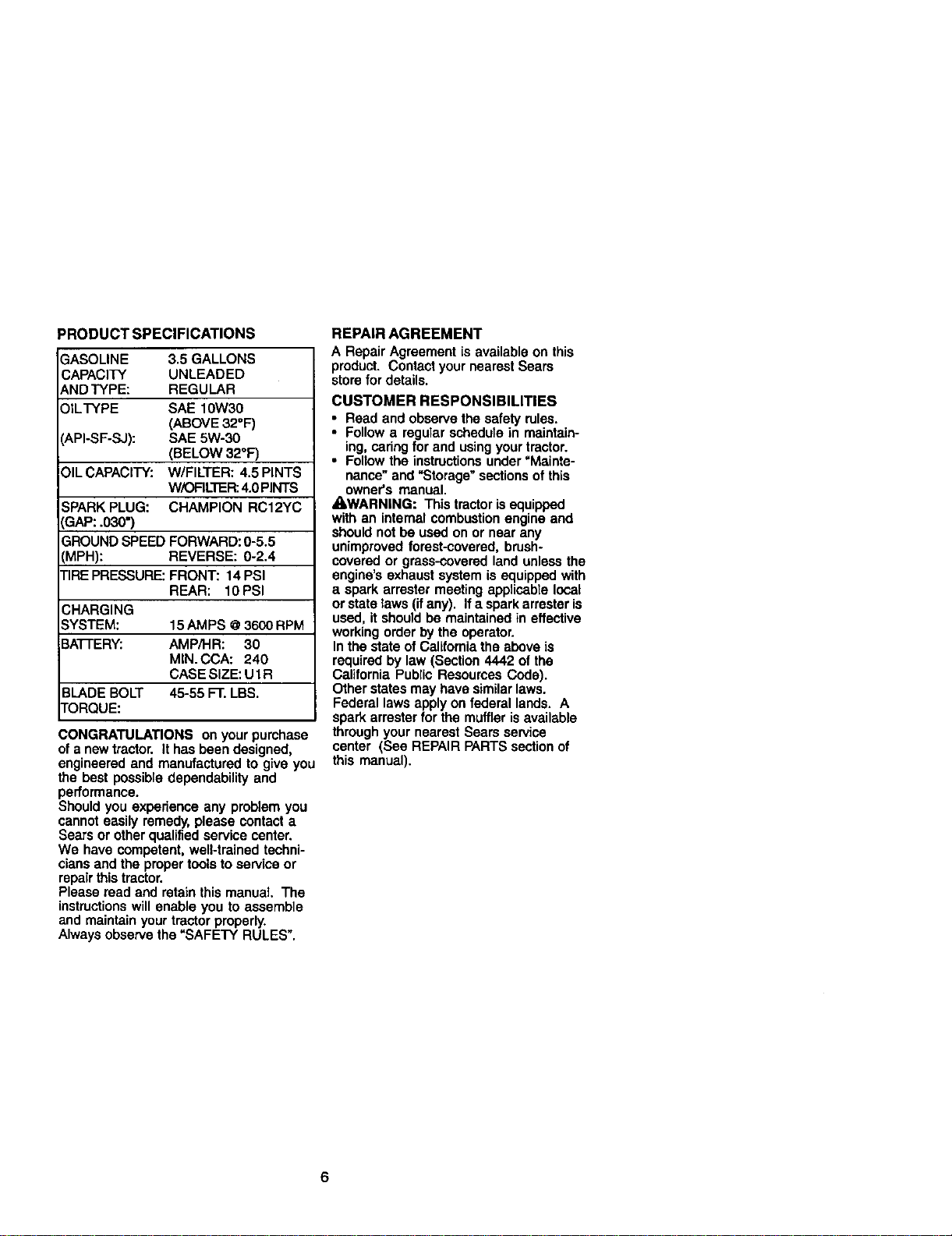
PRODUCT SPECIFICATIONS
GASOLINE 3.5 GALLONS
CAPACITY UNLEADED
AND TYPE: REGULAR
)ILTYPE SAE 10W30
(ABOVE 32°F)
_.PI-SF-SJ): SAE 5W-30
(BELOW 32°F)
DILCAPACITY: W/FILTER: 4.5 PINTS
WiOFILTER:4.0 PINTS
SPARK PLUG: CHAMPION RC12YC
3AP: .030")
SROUND SPEED FORWARD: 0-5.5
',MPH): REVERSE: 0-2.4
FIREPRESSURE: FRONT: 14 PSI
REAR: 10PSI
CHARGING
SYSTEM: 15AMPS @3600 RPM
3A'I-I'ERY: AMP/HR: 30
MIN. CCA: 240
CASE SIZE: U1 R
BLADE BOLT 45-55 FT. LBS.
FORQUE:
CONGRATULATIONS on your purchase
of a new tractor. It has been designed,
engineered and manufactured to give you
the best possible dependability and
performance.
Should you experience any problem you
cannot easily remedy, please contact a
Sears or other qualified service center.
We have competent, well-trained techni-
cians and the proper tools to service or
repair this tractor.
Please read and retain this manual. The
instructionswill enable you to assemble
and maintain your tractor properly.
Always observe the =SAFETY RULES".
REPAIR AGREEMENT
A Repair Agreement is available on this
product. Contact your nearest Sears
store for details.
CUSTOMER RESPONSIBILITIES
• Read and observe the safety rules.
• Follow a regular schedule in maintain-
ing, caring for and using your tractor.
• Follow the instructions under =Mainte-
nance" and "Storage" sections of this
owner's manual.
_WARNING: This tractor isequipped
with an internal combustion engine and
should not be used on or near any
unimproved forest-covered, brush-
covered or grass-covered land unless the
engine's exhaust system is equipped with
a spark arrester meeting applicable local
or state taws (ifany). If a spark arrester is
used, it should be maintained in effective
working order by the operator.
In the state of California the above is
required by law (Section 4442 of the
California Public Resources Code).
Other states may have similarlaws.
Federal laws apply on federal lands. A
spark arrester for the muffler isavailable
through your nearest Sears service
center (See REPAIR PARTS section of
this manual).
6
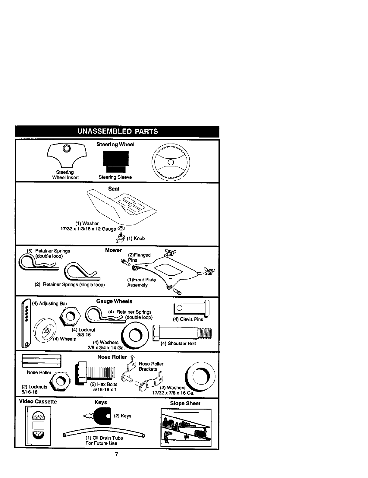
Steedng
Wheel Insert
Steering Wheel
Steenng Sleeve
Seat
(t) Washer
t7/32 x 1-3/16 x 12 Gauge (_
_(1) Knob
(5) Retainer Spdngs Mower
(2) Retainer Springs (single loop)
(1)Front Plate
Assembly
%
(4) Adjusting Bar IIC'_ _
_ (4)R_inerSp_ogs ©
_('_) eels (4) Washers _,_..../// L--_(4) Shoulder Bolt
3/8 x 3/4 x 14 Ga?_m,,,, _
I / Nose Roller_
I Nose Roll/e_ L"] _ Nose Roller__ _ Brackets , ...,_L \
(2) Losknuts _ _tt_.I. t "_( _ (2) Washers
5/16-18 ..... x. _ 17/32 x 7/8 x 16 Ga._
Video Cassette Keys
_ (2) Keys
For Future Use
Slope Sheet
(2) Ranged
Gauge Wheels
Yournewtractorhasbeenassembledatthefactorywithexceptionofthosepartsleft
unassembled for shipping purposes. To ensure safe and proper operation of your
tractor all parts and hardware you assemble must be tightened securely. Use the
correcttools as necessary to insure proper tightness. Review the video cassette before
you begin.
TOOLS REQUIRED FOR ASSEMBLY
A socket wrench set will make assembly
easier, Standard wrench sizes you need
are listed below,
(2) 9/16" wrench (1) 3/4" Socket w/
(1) 1/2" wrench drive ratchet
(1) Utility knife (1) Pliers
(1) Tire pressure gauge
When rightor left hand is mentioned in
this manual, it means, fromyour point of
view,when you are in the operating
position (seated behind the steering
wheel).
TO REMOVETRACTOR FROM
CARTON
UNPACK CARTON
1. Remove all accessible loose parts
and partscartons from carton.
2. Cut, from top to bottom, along lines on
all four corners of carton, and lay
panels flat.
3. Remove mower and packing materi-
als.
4. Check for any additional loose parts
or cartons and remove.
BEFORE REMOVINGTRACTOR
FROM SKID
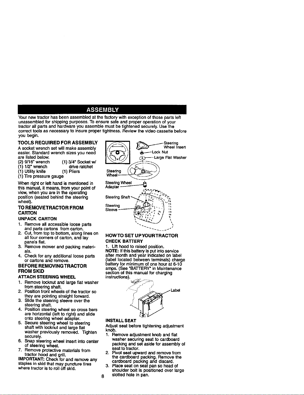
ATTACH STEERING WHEEL
1, Remove Iocknutand large flat washer
from steering shaft.
2. Position front wheels ofthe tractor so
they are pointingstraight forward.
3, Slide the steering sleeve over the
steering shaft,
4. Positionsteering wheel so cross bars
are horizontal (left to right) and slide
onto steering wheel adapter.
5. Secure steering wheel to steering
shaft with lecknut and large flat
washer previously removed. Tighten
securely.
6. Snap steering wheel insert into center
of steering wheel.
7. Remove protective materials from
tractor hood and grill.
IMPORTANT: Check for and remove any
staples in skid that may puncture tires
where tractor isto rolloff skid,
_'_ _.....--_ Steedng
I//_--_\1 l_=d=T WheelInsert
I( _70_ )1 _---Lo_ Nut
_ l_ga RatWasher
Steering / _._ _J)
SteeringWheel
Adapter_ =P
Steering s
Sleev
HOWTO SET UPYOURTRACTOR
CHECK BATTERY
1. Lift hood to raised position.
NOTE: If thisbattery is put intoservice
after month and year indicated on label
blabellocated between terminals) charge
artery for minimum of one hour at 6-10
amps. (See 'BATTERY" in Maintenance
section of this manual for charging
instructions).
INSTALL SEAT
Adjust seat before tighteningadjustment
knob.
1. Remove adjustment knob and flat
washer securing seat to cardboard
packing and set aside for assembly of
seat to tractor.
2. Pivot seat upward and removefrom
the cardboard packing. Remove the
cardboard packing and discard.
3. Place seat on seat pan so head of
shoulder bolt is positioned over large
8 slotted hole in pan.
4. Pushdown on seat to engage
shoulder bolt in slotand pull seat
towards rear oftractor.
5. Pivot seat and pan forward and
assemble adjustment knob and flat
washer loosely. Do not tighten.
6. Lower seat into operating position and
sit in seat.
7. Slide seat until a comfortable position
is reached which allows you to press
clutch/brake pedal all the way down.
8. Get off seat without moving its
adjusted position.
9. Raise seat and tighten adjustment
knob securely.
Seat
Shoulder
Bolt
NOTE: You may now rollor drive your
tractor off the skid. Follow the appropriate
instructionbelow to remove the tractor
from the skid,
TO ROLLTRACTOR OFF SKID (See
Operation section for location and
function of controls)
1. Press lift lever plunger and raise
attachment lift lever to its highest
position.
2. Release parking brake by depressing
brake pedal.
3. Place freewheel control in freewheel-
ing position to disengage transmis-
sion(See "TO TRANSPORT" inthe
Operation section of this manual).
4. Roll tractorforward off skid.
TO DRIVETRACTOR OFF SKID (See
Operation section for location and
function of controls)
_, WARNING: Before starting, read,
understand and follow all instructionsin
the Operation section of this manual. Be
sure tractor is in a well-ventilated area. Be
sure the area in front oftractor isclear of
other people and objects.
9
t. Be sure all the above assembly steps
have been completad.
2. Check engine oil level and fill fuel
tank with gasoline.
3. Place freewheel control in "transmis-
sion engaged" position.
4. Sit on seat in operating position,
depress brake pedal and set the
parking brake.
5. Press lift lever plunger and raise
attachment lift lever to its highest
position.
6. Start the engine. After engine has
started, move throttle control to idle
position.
7. Release parking brake.
8. Slowly depress forward drive pedal
and drive tractor off skid.
9. Apply brake to stop tractor and set
parking brake.
10.Turn ignition key to "OFF" position.
Continue with the instructions that follow.
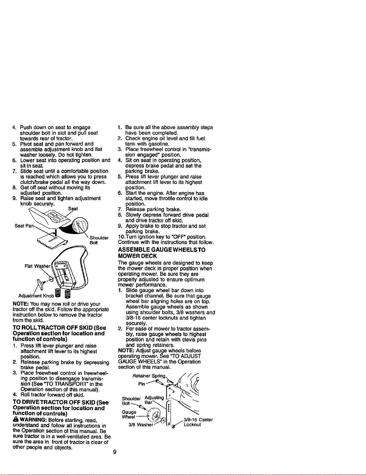
ASSEMBLE GAUGEWHEELSTO
MOWER DECK
The gauge wheels are designed to keep
the mower deck in proper position when
operating mower. Be sure they are
properly adjusted to ensure optimum
mower performance.
1. Slide gauge wheel bar down into
bracket channel, Be sure that gauge
wheel bar aligning holes are on top.
Assemble gauge wheels as shown
using shoulder bolts, 3/8 washers and
3/8-16 center Iocknuts and tighten
securely.
2. For ease of mower totractor assem-
bly, raise gauge wheels to highest
position and retain with clevis pins
and spdng retainers.
NOTE: Adjust gauge wheels before
operating mower. See "TO ADJUST
GAUGE WHEELS" in the Operation
section of this manual.
Retainer
Pin_
Shoulder
Gauge
3/8-16
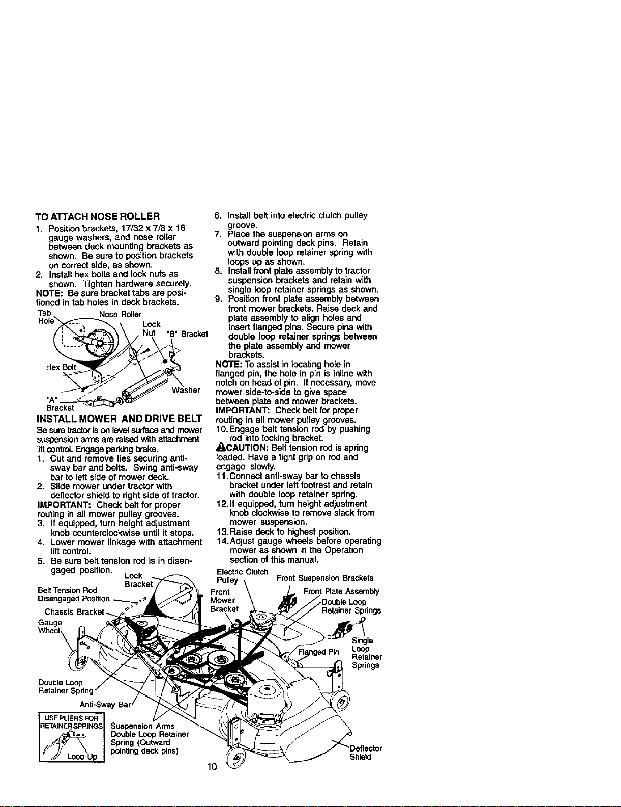
TO AI-rACH NOSE ROLLER
1. Position brackets, 17/32 x 7/8 x 16
gauge washers, and nose miler
between deck mounting brackets as
shown. Be sure to position brackets
on correct side, as shown.
2. Install hex bolts and lock nuts as
shown. Tighten hardware securely.
NOTE: Be sure bracket tabs are posi-
tioned in tab holes in deck brackets.
Tab Nose Roller
Lock
"B" Bracket
Hax Bol
Bracket
INSTALL MOWER AND DRIVE BELT
Be suretractorisonleve_surface and mower
suspensionarmsare raisedwithattachn_wt
liftcontrol.Engageparkingbrake.
1. Cut and remove ties securing anti-
sway bar and belts. Swing anti-sway
bar to left side of mower deck.
2. Slide mower under tractor with
deflector shield to right side oftractor.
IMPORTANT: Check belt for proper
routingin all mower pulley grooves.
3. If equipped, turn height adjustment
knob countemlockwise until it stops.
4. Lower mower linkage with attachment
lift control.
5. Be sure belt tension rod is in disen-
gaged position. Lock
Belt Tension Rod
Disengaged
ChassLs Brackat_
Gauge
Double Loop
Retainer Spnng
Anti-Sway
USEPLIERSFOR
RETAJNERSPRINGSSuspension Arms
Double Loop Retainer
Spring (Outward
Up pointing deck pins)
6. Install belt into electric clutchpulley
groove.
7. Place the suspension arms on
outward pointingdock pins. Retain
with double loop retainer spr_ngwith
loops up as shown.
8. Install front plate assembly to tractor
suspension brackets and retain with
single loop retainer springs as shown.
9. Position front plate assembly between
front mower brackets. Raise deck and
plate assembly to align holes and
insertflanged pins. Secure pins with
double loop retainer springs between
the plate assembly and mower
brackets.
NOTE: To assist in locating hole in
flanged pin, the hole in pin is inUne with
notchon head of pin. If necessary, move
mower side-to-side to give space
between plate and mower brackets.
IMPORTANT: Chock belt for proper
routingin all mower pulley grooves.
10. Engage belt tension rod by pushing
rod into locking bracket.
_kCAUTION: Belt tension rodis spring
loaded. Have a tight grip on rod and
engage slowly.
11.Connect anti-sway bar to chassis
bracket under left footrest and retain
with double loop retainer spring.
12.If equipped, turn height adjustment
knob clockwiseto remove slack from
mower suspension.
13. Raise deck to highest position.
14.Adjust gauge wheels before operating
mower as shown in the Operation
section ot this manual.
Electdc Clutch
Pulley Front Suspension Brackets
Front Front Plate Assembly
Mower _Doubla Loop
Bracket Retainer Springs
Single
Loop
Retainer
Springs
10
Shield
CHECKTIRE PRESSURE
The tires on your tractor were overinflated
at the factory for shipping purposes.
Correct tire pressure is importantfor best
cutting performance.
• Reduce tire pressure to PSI shown in
"PRODUCT SPECIFICATIONS" section
ofthis manual.
CHECK DECK LEVELNESS
For best cuttingresults, mower housing
should be properly leveled. See "TO
LEVEL MOWER HOUSING" in the
Service and Adjustments section ofthis
manual,
CHECK FOR PROPER POSITION OF
ALL BELTS
See the figuresthat are shown for
replacing motion and mower blade drive
belts in the Service and Adjustments
section of this manual. Verify that the
belts are routedcorrectly.
CHECK BRAKE SYSTEM
After you team how to operate your
tractor,check to see that the brake is
propedyadjusted. See "TO ADJUST
BRAKE" in the Service and Adjustments
section of this manual.
V"CHECKLIST
BEFORE YOU OPERATE AND ENJOY
YOUR NEW TRACTOR, WE WISH TO
ASSURE THAT YOU RECEIVE THE BEST
PERFORMANCE AND SATISFACTION
FROM THIS QUALITY PRODUCT.
PLEASE REVIEWTHE FOLLOWING
CHECKLIST:
/ All assembly instructions have been
completed.
,/No remaining loose parts in carton.
,/Battery is propedy prepared and
charged. (Minimum 1 hour at 6 amps).
,/Seat is adjusted comfortablyand
tightened securely.
,/All tires are propedy inflated. (For
shipping purposes, the tires were
ovednflated at the factory).
4 Be sure mower deck is properly leveled
side-to-side/front-to-rear for best cutting
results. (Tires must be propedy inflated
for leveling).
/ Check mower and drive belts. Be sure
they are routed propedy around pulleys
and inside all belt keepers.
/ Check wiring. See that all connections
are stillsecure and wires are properly
clamped.
,/Before drivingtractor, be sure free-
wheel control is in drive position.
WHILE LEARNING HOW TO USE YOUR
TRACTOR, PAY EXTRA A'I-]'ENTION TO
THE FOLLOWING IMPORTANT ITEMS:
,," Engine oil is at proper level.
/ Fueltank isfilled with fresh, clean,
regular unleaded gasoline.
,/Become familiarwith all controls- their
location and function. Operate them
before you start the engine.
,/Be sure brake system is in safe
operating condition.
/ It is importantto purge the transmission
before operating your tractor for the first
time. Follow proper starting and
transmission purging instructions(See
"TO START ENGINE" and "PURGE
TRANSMISSION" in the Operation
section of this manual).
11
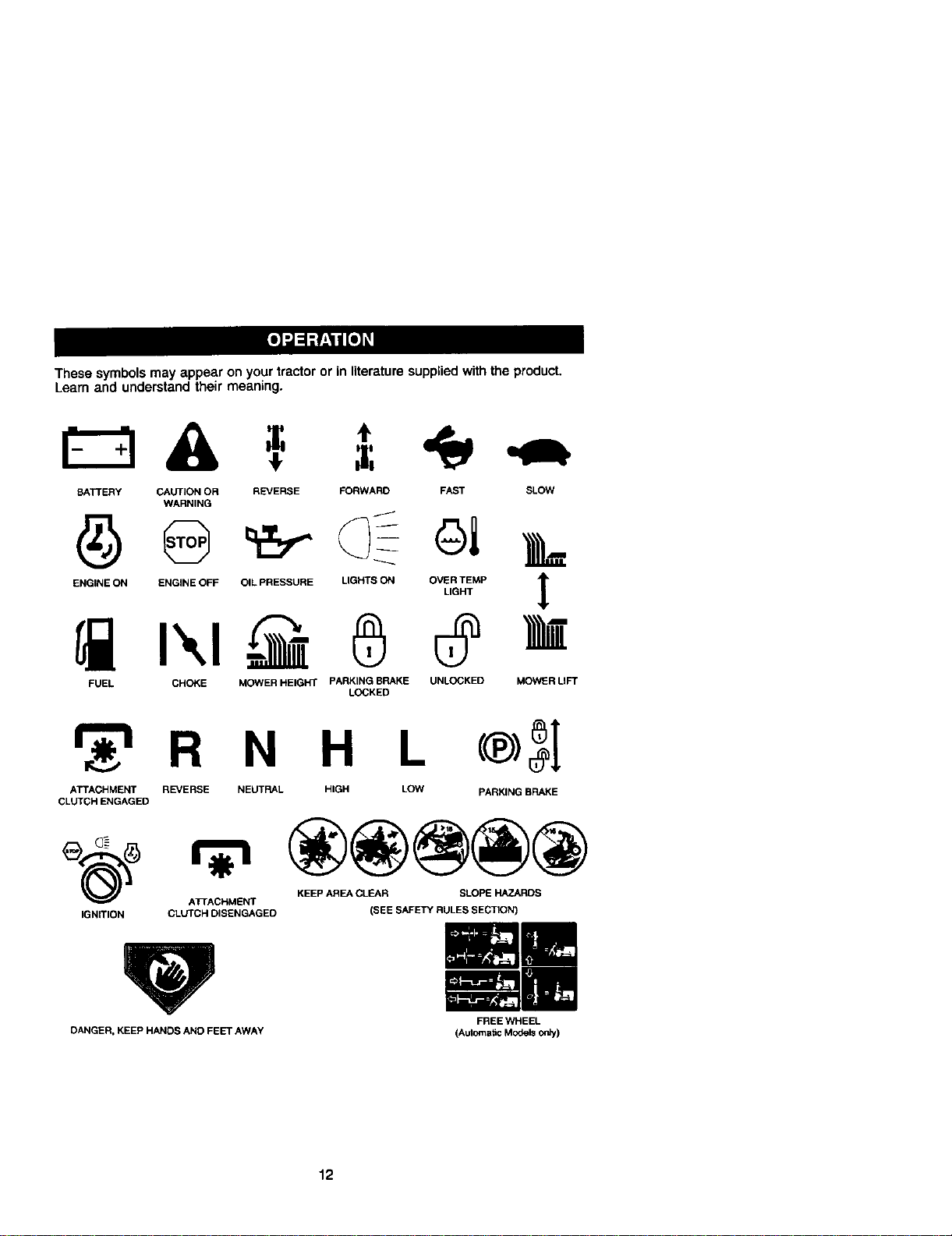
These symbols may appear on your tractor or in literaturesupplied with the product.
Learn and understand their meaning.
BATTERY CAUTION OR REVERSE FORWARD FAST SLOW
WARNING
E.O,NEO.ENO,NEOEFO.LPRESSOREUaHTSO.O_E_P |
4"
FUEL CHOKE MOWER HEIGHT PARKING BRAKE UNLOCKED MOWER LIFT
LOCKED
r 'l R N H L
ATTACHMENT REVERSE NEUTRAL HIGH LOW PARKING BRAKE
CLUTCH ENGAGED
KEEP AREA CLEAR SLOPE HAZARDS
ATrACHMENT
IGNITION CLUTCH DISENGAGED (SEE SAFETY RULES SECTION)
DANGER, KEEP HANDS AND FEET AWAY
FREE WHEEL
(Automatic Models only)
12
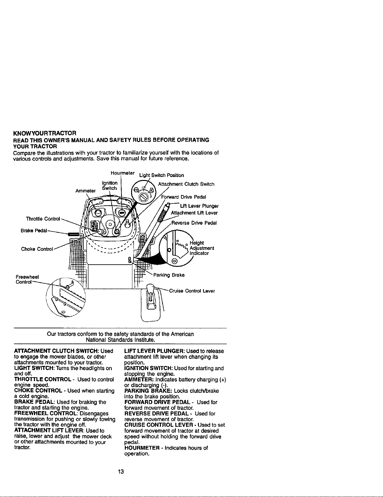
KNOWYOURTRACTOR
READ THIS OWNER'S MANUAL AND SAFETY RULES BEFORE OPERATING
YOUR TRACTOR
Compare the illustrationswith your tractor to familiarize yourself with the locations of
various controlsand adjustments. Save this manual for future reference.
Ammeter
Hourmeter LLghtSwitch Position
Ignition Attachment Clutch Switch
Switch
Drive Pedal
Plunger
Attachment Lift Lever
Reverse Drive Pedal
Adjustment
Freewheel
Brake
Lever
Our tractors conformto the safety standards of the American
National Standards Institute.
A'I'rACHMENT CLUTCH SWITCH: Used
to engage the mower blades, or other
attachments mounted to your tractor.
LIGHT SWITCH: Turns the headlightson
and off.
THRO'I-I'LE CONTROL - Used to control
engine speed.
CHOKE CONTROL - Used when starting
a cold engine.
BRAKE PEDAL: Used for brakingthe
tractor and starting the engine.
FREEWHEEL CONTROL: Disengages
transmission for pushing or slowly towing
the tractor with the engine off.
ATTACHMENT LIFT LEVER: Used to
raise, lower and adjust the mower deck
or other attachments mounted to your
tractor.
LIFT LEVER PLUNGER: Usedto release
attachment liftlever when changing its
position.
IGNITION SWITCH: Used for startingand
stopping the engine.
AMMETER: Indicates batterycharging (+)
or discharging (-).
PARKING BRAKE: Locks clutch/brake
into the brake position.
FORWARD DRIVE PEDAL - Used for
forward movement of tractor.
REVERSE DRIVE PEDAL- Used for
reverse movement of tractor.
CRUISE CONTROL LEVER - Used to set
forward movement of tractor at desired
speed without holdingthe forward drive
pedal.
HOURMETER - Indicates hours of
operation.
13
The operation of any tractor can result in foreign objects thrown intothe I
eyes, which can resultin severe eye damage. Always wear safety glasses
or eye shields while operating your tractor or performing any adjustments
or repairs. We recommend a wide vision safety mask over spectacles, or
standard safety glasses. I
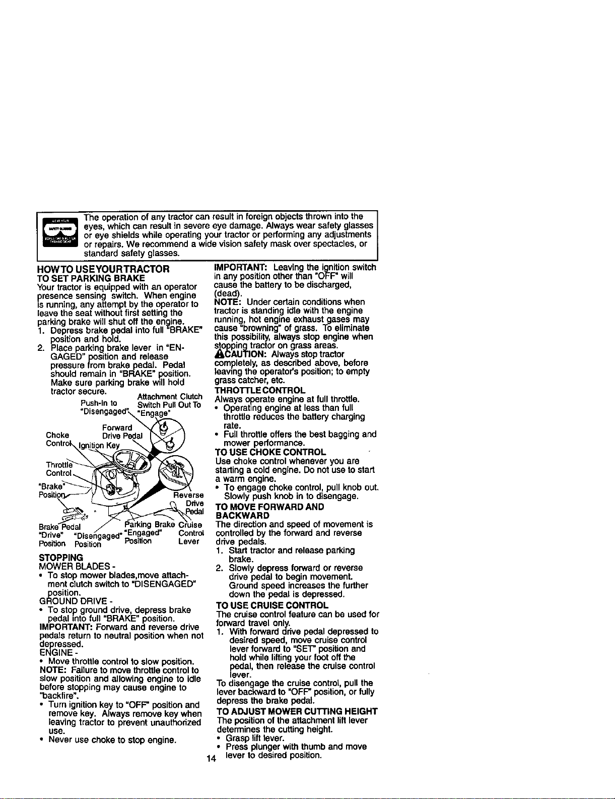
HOWTO USEYOURTRACTOR
TO SET PARKING BRAKE
Your tractor is equipped with an operator
presence sensing switch. When engine
is running,any attempt by the operator to
leave the seat without first setting the
parking brake will shut off the engine.
1. Depress brake pedal into full "BRAKE"
position and hold.
2. Place parking brake lever in "EN-
GAGED" position and release
pressure from brake pedal. Pedal
should remain in "BRAKE" .Ro.sition.
Make sure parking brake wdl hold
tractor secure.
AttachmentClutch
Push-into SwitchPullOutTo
"Disengaged"_ngag_._
Forward _ t_ _A
Choke DrivePedal I_"-._ , )
con,ro
c or r iT
"Brake"_"'_ j_
Dr've Disengaged ..
Position Position Position Lever
STOPPING
MOWER BLADES -
• To stop mower blades,move attach-
merit clutchswitch to "DISENGAGED"
position.
GROUND DRIVE -
• To stop ground drive, depress brake
pedal into full "BRAKE" position.
IMPORTANT: Forward and reverse drive
pedsls return to neutral positionwhen not
depressed.
ENGINE -
• Move throttle controlto slow position.
NOTE: Failure to move throttlecontrol to
slow position and allowing engine to idle
before stopping may cause engine to
"backfire_.
• Turn ignition key to =OFF' position and
remove key. Always remove key when
leaving tractor to prevent unauthorized
use.
• Never use choke to stop engine.
IMPORTANT: Leaving the ignitionswitch
in any position other than "OFF" will
cause the battery to be discharged,
(dead).
NOTE: Under certain conditions when
tractor is standing idlewith the engine
running, hot engine exhaust gases may
cause"browning" of grass. To eliminate
this possibility, always stop engine when
_(_ping tractor on grass areas.
AUTION: Always stop tractor
completely, as described above, before
leawng the operator's position; to empty
grass catcher, etc.
THROTrLE CONTROL
Always operate engine at full throttle.
• Operating engine at lessthan full
throttle reduces the battery charging
rate.
• Full throttleoffers the best bagging and
mower performance.
TO USE CHOKE CONTROL
Use choke control whenever you are
starting a cold engine. Do notuse tostart
a warm engine.
• To engage choke control, pull knob out.
Slowly push knob in to disengage.
TO MOVE FORWARD AND
BACKWARD
The direction and speed of movement is
controlledby the forward and reverse
drive pedals.
1. Start tractor and release parking
brake.
2. Slowly depress forwardor reverse
drive pedal to begin movement.
Ground speed increases the further
down the pedal is depressed.
TO USE CRUISE CONTROL
The cruise controlfeature can be used for
forward travel only.
1. With forward drive pedal depressed to
desired speed, move cruise control
lever forward to "SET" positionend
holdwhile liftingyour foot off the
e_veal,then release the cruise control
r.
To disengage the cruise controt, pull the
lever backward to "OFF" position,or fully
depress the brake pedal
TO ADJUST MOWER CUTTING HEIGHT
The position of the attachment liftlever
determines the cuttingheight.
• Grasp liftlever.
Press plunger with thumb and move
14° lever to desired position.
Thecuttingheightrangeisapproxi-
mately 1-1/2to 4". The heights are
measured from the ground to the blade
tipwith the engine notrunning. These
heights are approximate and may vary
depending upon soil conditions,height of
grass andtypes of grass being mowed.
• The average lawn should be cut to
approximately 2-1/2 inches during the
coolseason and to over 3 inches
dudng hot months• For healthier and
better looking lawns, mow often and
after moderate growth.
• For best cuttingperformance, grass
over 6 inches _nheight sheutd he
mowed twice. Make the firstcut
relatively high;the second to desired
height.
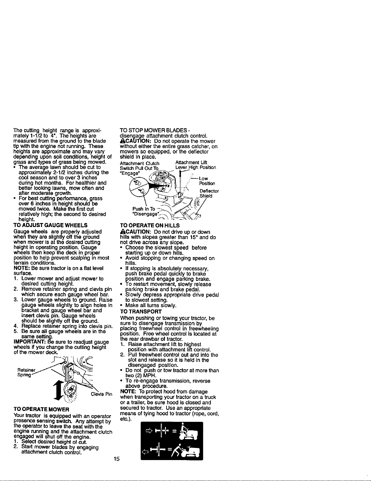
TO ADJUST GAUGE WHEELS
Gauge wheels are properly adjusted
when they are slightlyoff the ground
when mower is at the desired cutting
height in operating position. Gauge
wheels then keep the deck in proper
positionto help prevent scalping m most
terrain conditions.
NOTE: Be sure tractor is on a flat level
surface.
1. Lower mower and adjust mower to
desired cutting height•
2. Remove retainer spring and clevis pin
which secure each gauge wheel bar.
3. Lower gauge wheels to ground. Raise
gauge wheels slightlyto align holes in
bracket and gauge wheel bar and
insert clevis pin. Gauge wheels
. should be slightlyoff the ground•
Replace retainer springinto clevis pin.
• Be sure all gauge wheels are in the
same setting.
IMPORTANT: Be sure to readjust gauge
wheels if you change the cuttingheight
ofthe mower deck.
Retainer
Sprint
TO OPERATE MOWER
Your tractor is equipped with an operator
presence sensing switch. Any attempt by
the operator to leave the seat with the
engine runningand the attachment clutch
engaged will shut off the engine•
1. Select desired height of cut.
2. Start mower blades by engaging
attachment clutch control.
15
TO STOP MOWER BLADES -
disengage attachment clutch control.
_,CAUTION: Do not operate the mower
without either the entire grass catcher, on
mowers so equipped, or the deflector
shield in place.
AttachmentClutch AttachmentLift
SwitchPullOutTo LeverHigh Position
"Engage" /_ r- ?
_,,_ _/ \_\ Deflector
PushInTo _ L_" ":/
TO OPERATE ON HILLS
ACAUTION: DO not drive up or down
hills with slopes greater than 15° and do
not ddve across any slope.
• Choose the slowest s_eed before
• stading up or down h=lls.
Avoid stopping or changing speed on
hills.
ll stopping is absolutely necessary,
push brake pedal quickly to brake
position and engage parking brake.
To restart movement, slowly release
parking brake and brake pedal.
Slowly depress appropriate drive pedal
to slowest setting.
Make all turns slowly.
TO TRANSPORT
When pushing or towingyour tractor,be
sure to disengage transmission by
placing freewheel control in freewheeling
position. Free wheel control is located at
the rear drawbar oftractor.
1. Raise attachment liftto highest
position with attachment lilt control.
2. Pull freewheel control out end intothe
slot and release so it is held in the
disengaged position.
• Do not push or towtractorat morethan
two (2) MPH.
• To re-engsgo transmission, reverse
above procedure.
NOTE: To protect hood from damage
when transporting your tractor on a truck
or a trailer,be sure hood isclosed and
secured to tractor. Use an appropriate
means of tying hoodto tractor (rope, cord,
etc.).
TOWINGCARTSANDOTHERATrACH-
MENTS
Towonlytheattachmentsthatare
recommendedbyandcomplywith
specificationsofthemanufacturer of your
tractor.Use common sense when towing.
Too heavy of a load, while on a slope, is
dangerous. Tires can lose traction with
the ground and cause you to lose control
ofyourtractor.
BEFORE STARTINGTHE ENGINE
CHECK ENGINE OIL LEVEL
The engine in your tractor has been
shipped, from the factory, already filled
with summer weight oil.
1. Check engine oil with tractor on level
ground.
2. Unthraed and remove oil fill cap/
dipstick;wipe oil off. Reinsert the
dipstick intothe tube and rest oil fill
cap on the tube. Do not thread the
cap onto the tube. Remove and read
oil level. If necessary, add oiluntil
"FULL" mark on dipstick is reached.
Do not overfill.
• For cold weather operation you should
change oilfor easier starting (See =OIL
VISCOSITY CHART" in the Mainte-
nance section ofthis manual).
• To change engine oil,see the Mainte-
nance sectionin this manual.
ADD GASOLINE
• Fillfuel tank. Use fresh, clean, regular
unleaded gasoline with a minimum of
87 octane. (Use of leaded gasoline will
increase carbon and lead oxide
deposits and reduce valve life). Do not
mix oil with gasoline. Purchase fuel in
quantitiesthat can be used within 30
days to assure fuel freshness.
IMPORTANT: When operating in tem-
peratures below 32°F(0°C), use fresh,
clean winter grade gasoline to help
insure good cold weather starting.
_,WARNING: Experience indicates that
alcohol blended fuels (called gasohol or
using ethanol or methanol) can attract
moisture which leads to separation and
formation of acids during storage. Acidic
gas can damage the fuel system of an
engine while in storage. To avoid engine
problems, the fuel system should be
emptied before storage of 30 days or
longer. Drain the gas tank start the
engine and let it run until the fuel lines
and carburetor are empty. Use fresh fuel
next season. See Storage Instructions for
additional information. Never use engine
or carburetor cleaner products in the fuel
tank or permanent damage may occur.
A,CAUTION: Fillto bottom ofgas tank
filler neck. Do not overfill.Wipe offany
spilled oil or fuel. Do not store, spillor use
gasoline near an open flame.
TO START ENGINE
When starting the engine forthe firsttime
or if the engine has run outof fuel, it will
take extra cranking time to move fuel from
the tank to the engine.
1. Be sure freewheel control is in the
transmission engaged position.
2. Sit on seat in operating position,
depress brake pedal and set parking
brake.
3. Move attachment clutchto "DISEN-
GAGED" position.
4. Move throttle controlto fast position
5. Pull choke control outfor a cold
engine start attempt. For a warm
engine start attempt the choke control
may notbe needed.
NOTE: Before starting,read the warm and
cold starting procedures below.
6. Insert key into ignitionand turn key
clockwise to =START" position and
release key as soon as engine starts.
Do not run starter continuouslyfor
more than fifteen seconds per minute.
If the engine does not start after
several attempts, push choke control
in, wait a few minutes and try again. If
engine still does not start, pull the
choke control out and retry.
WARM WEATHER STARTING (50° F and
above)
7, When engine starts, slowlypush
choke control in until the engine
begins to run smoothly. Ifthe engine
starts to run roughly, pull the choke
control out slightlyfor a few seconds
and then continue to push the control
in slowly.
• The attachments and ground drive can
now be used. If the engine does not
accept the load, restart the engine and
allow it towarm up for one minute
using the choke as described above.
COLDWEATHER STARTING (50 =F and
below)
7. When engine starts, slowly push
choke control in untilthe engine
begins to run smoothly. Continue to
push the choke control in small steps
allowing the engine to accept small
changes in speed and load, until the
choke control isfully in. Ifthe engine
startsto run roughly,pull the choke
control out slightlyfor a few seconds
and then continue to push the control
in slowly. This may require an engine
warm-up peded from several seconds
to several minutes, depending on the
16 temperature.
AUTOMATICTRANSMISSIONWARM UP
Before driving the unit in cold weather,
the transmission should be warmed up as
follows:
1. Be sure the tractor is on level ground.
2. Release the parking brake and let the
brake slowly return to operating
position.
3. Allow one minute for transmission to
warm up. This can be done during the
engine warm up period.
• The attachments can be used during
the en_line warm-up period after the
transmtssion has been warmed up and
may require the choke control be
pulled out slightly.
NOTE: Ifat a highaltitude (above 3000
feet) or in coldtemperatures (below 32 F)
the carburetor fuel mixture may need to
be adjusted for best engine pedormance.
See "TO ADJUST CARBURETOR in the
Service and Adjustments section ofthis
manual.
PURGETRANSMISSlON
A,CAUTION: Never engage or disengage
freewheel lever while the engine is
running.
To ensure proper operation and pedor-
mance, itis recommendedthat the
transmissionbe purged before operating
tractorfor the firsttime.Thisprocadure will
removeany trapped air inside the trans-
mission which may have developed during
shippingof yourtractor.
IMPORTANT: Shouldyour transmission
require removalfor serviceor replacement,
it shouldbe purged after reinstailation
beforeoperatingthe tractor.
1. Place tractor safely on level surface
with engine off and parking brake set.
2. Disengage transmission by placing
freewheel control in freewheeling
position(See "TO TRANSPORT" in
this section of manual).
3. Sittingin the tractor seat, start engine.
After the engine is running, move
throttlecontrol to slow position.
Disengage parking brake.
4. Depress forward drive pedal to full
forward position and hold for five (5)
seconds and release pedal. Depress
reverse ddve pedal to full reverse
positionand hold for five (5) seconds
and release pedal. Repeat this
procedure three (3) times.
NOTE: Dudngthis procedurethere willbe
no movementof drivewheels. The airis
being removed from hydraulicddve
system.
5. Shut- oft engine and set parking
brake.
6. Engage transmission by placing
freewheel control in driving position
(See "TO TRANSPORT" in this section
of manual).
7. Sitting in the tractor seat, start engine.
After the engine is running, move
throttle control to half (1/2)speed.
Disengage parking brake.
8. Drive tractor forward for approximately
five feet then backwards for five feet.
Repeat this driving procedure three
times.
Your tractor is now purged and now ready
for normal operation.
MOWINGTIPS
• Mower should be properly leveled for
best mowing performance. See "TO
LEVEL MOWER HOUSING" inthe
Service and Adjustmentssection of this
manual.
• The left hand side of mower should be
used for trimming,
• Ddve so that clippings are discharged
onto the area that has been cut. Have
the cut area to the right of the tractor.
This will result in a more even distribu-
tion of clippings and more uniform
cutting.
• When mowing large areas, start by
turning to the right so that clippings will
discharge away from shrubs, fences,
driveways, etc. After one or two
rounds, mow in the opposite direction
making left hand turns until finished.
• If grass is extremely tall, it should be
mowed twice to reduce load and
possible fire hazard from dried clip-
pings. Make first cut relatively high; the
second to the desired height.
• Do not mow grass when it is wet. Wet
grass will plug mower and leave
undesirable clumps. Allow grassto dry
before mowing.
• Always operate engine at full throttle
when mowing to assure better mowing
performance and proper discharge of
matedai. Regulate ground speed by
selecting a low enough gear to give the
mower cuttingperformance as well as
the quality of cut desired.
• When operatingattachments, select a
ground speed that will suitthe terrain
and give best performance of the
attachment being used.
f
f
17
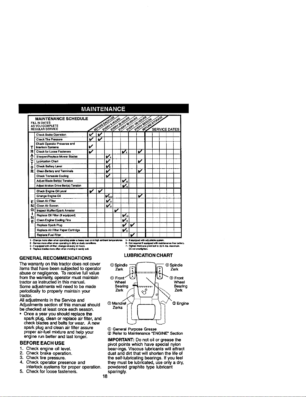
M..°TO...CESC.EOOL
FILL IN DATES
REGUL._R SERVICE RVICE DATES
Check Brake OperaSon _ f_
]Ch_k_,eP,.*u,e V' t/
Check Operator Preserlce and
T Interlock Systems t/e
R Chec_ f01"L0ose Fastenem (1_ (1_7 _e
Sharpen/R apiece Mower Blades 11_4
T Lub_n Chert _ _
R clean Batterywxl Termlnaa It/ I_/
Check Tr_ns_ae C_l_ _
AdjustBladeBelt(s)Tensk_ tt/s
AdjustMO_O_DriveBelt(s)Tensloe Ks
CheckEngineO_1Level _ b/
ChelaEr_o _l _i _
E Clean Ale Filet _=
N Clean ALrScreen 1_2
G Inspect Muffler/Spark Arre=t er I1_
Replece OII Filter (If equlpp4gd) _1,2
N Clean Englne Cooling F_s I_1
Rel_,ce AirRlter PaperCartddpe b/_
Rep4ace Fuel Niter _1_
I *Ct_r_i morn_ v,_i,,opemt;nour,d_-I hmvyloador lahigh_ent torr_peete.'o_ 5 - iio_r_k:_ed_1_ edlun_ sysm'_.
2. Ssrv_emor=dt Jnw_enccer_ir_ Indbly_- duzlyco,td_,tt. 6 - k_ mqt_nzdI/_quip_zdwl_ raa_-k_ bar.cry.
3. Ifiq_ed WtlhOllIg_ _,ge o_m*_y50 hours. 7. Tlgh_,flh_t _xl=pivotbo_tto35 ILJ_. m.lu(kn;_.
4 - Reel_=bk=_=rae_ oaoeW_,I movtbgInsanW_. DOr_ o,'erlk_mn.
GENERAL RECOMMENDATIONS
The warranty onthis tractor doesnotcover
items that have been subjected to operator
abuse or negligence. To receive full value
from the warranty,operator must maintain
tractoras instructedin this manual.
Some adjustmentswill need to be made
periodically to properly maintain your
tractor.
All adjustments in the Service and
Adjustmentssection of this manual should
be checkedat least once each season.
• Once a year you should replace the
spark plug, clean or replace air filter, and
check blades and beltsfor wear. A new
spark plugand clean air filter assure
proper air-fuel mixtureand help your
engine run better and last longer.
BEFORE EACH USE
1. Check engine oil level.
2. Check brake operation.
3. Check tire pressure.
4. Check operator presence and
interlock systems for proper operation.
5. Check for loose fasteners.
LUBRICATION CHART
_) Spindle
Zerk Zerk
Wheel
Bearing
Zerk
Wheel
Bearing
Zerk
ZeUs
L.....= _.....,
_)Gener_ Purpose Grease
_) Refer to Maintenance =ENGINE" Section
IMPORTANT: Do not oil or grease the
pivot points which have special nylon
bear-ings. Viscous lubricants will attract
dust and dirtthat will shorten the life of
the self-lubricatingbearings. If you feel
they must be lubricated, use only a dry,
powdered graphite type lubricant
sparingly.
18
TRACTOR
Alwaysobservesafetyrules when
performing any maintenance.
BRAKE OPERATION
If tractorrequires more than six (6) feet
stopping distance at high speed in
highestgear, then brake must be ad-
justed. (See "TO ADJUST BRAKE" inthe
Service and Adjustments section of this
manual).
TIRES
• Maintain proper air pressure in all tires
(See "PRODUCT SPECIFICATIONS"
section of this manual).
• Keep tires free of gasoline, oil, or insect
control chemicals which can harm
rubber.
• Avoid stumps, stones, deep ruts, sharp
objects and other hazards that may
cause tire damage.
NOTE: To seal tire punctures and prevent
flat tires due to slow leaks, tire sealant
may be purchasedfrom your local parts
dealer. Tire sealant also preventstire dry
rot and corrosion.
OPERATOR PRESENCE SYSTEM
Be sure that operator presence and
interlock systems are working properly. If
your tractor does not function as de-
scribed below, repair the problem
immediately.
• The engine should not start unless the
brake pedal is fully depressed and
attachment clutch control is in the
disengaged position.
• When the engine is running, any
attempt by the operatorto leave the
seat without first setting the parking
brake should shut off the engine.
• When the engine is running and the
attachment clutch is engaged, any
attempt by the operator to leave the
seat should shut off the engine.
• The attachment clutch should never
operate unless the operator is in the
seat.
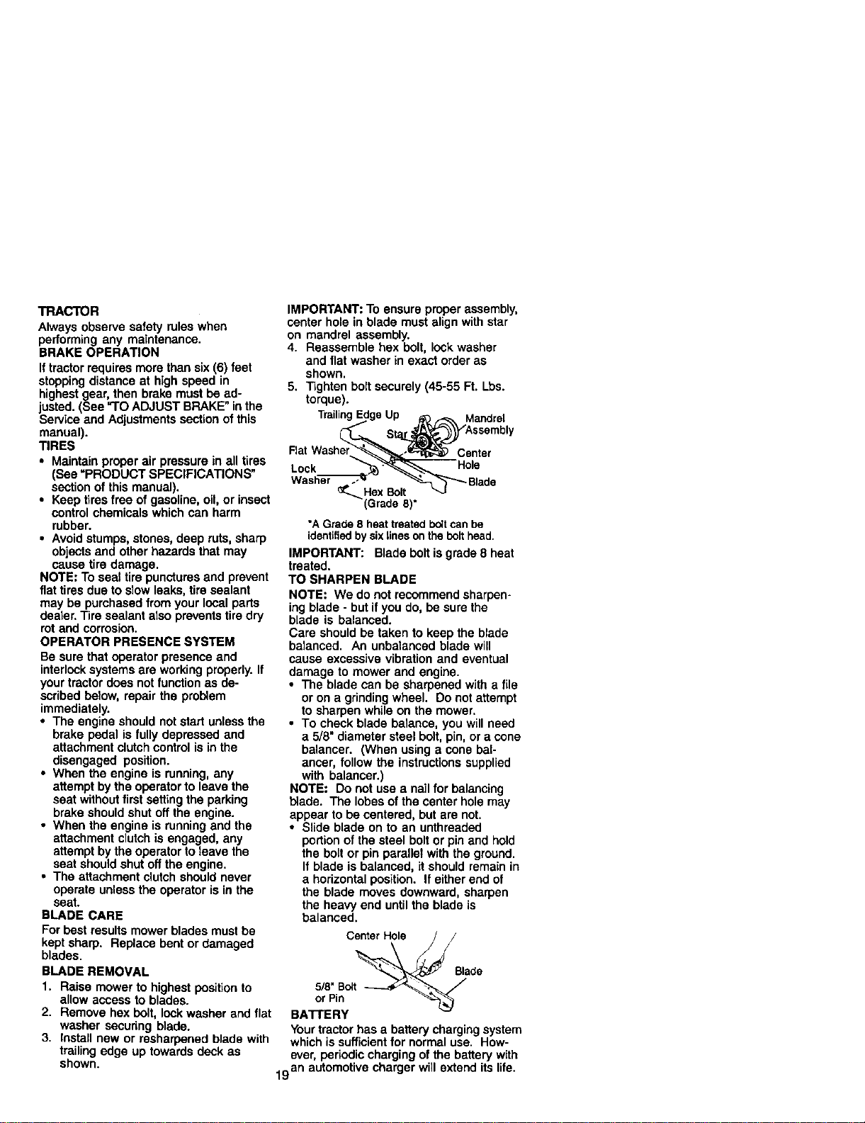
BLADE CARE
For best results mower blades must be
kept sharp. Replace bent or damaged
blades.
BLADE REMOVAL
1. Raise mower to highest position to
allow access to blades.
2. Remove hex bolt, lock washer and flat
washer securing blade.
3. Install new or rasharpened blade with
trailingedge up towards deck as
IMPORTANT: To ensure proper assembly,
center hole in blade must align with star
on mandrel assembly.
4. Reassemble hex bolt, lock washer
and flat washer in exact order as
shown.
5. Tighten bolt securely (45-55 Ft. Lbs.
torque).
TrailingEdgeUp _:_ _ Mandrel
St_ '_ssembly
FlatWasher_--_,=._:_ Center
Lock "__Hols
Wash_ _"_-_"_1""_ Blade
(Grade8)
*AGrade 8 heat treatedboltcanbe
identifiedby sixlinesonthebolthead.
IMPORTANT: Blade bolt isgrade 8 heat
treated.
TO SHARPEN BLADE
NOTE: We do not recommend sharpen-
ing blade - but if you do, be sure the
blade is balanced.
Care should be taken to keep the blade
balanced. An unbalanced blade will
cause excessive vibration and eventual
damage to mower and engine.
• The blade can be sharpened with a file
or on a grindingwheel. Do notattempt
to sharpen while on the mower.
• To check blade balance, you will need
a 5/8" diameter steel bolt, pin, or a cone
balancer. (When using a cone bal-
ancer, follow the instructionssupplied
with belancar.)
NOTE: Do not use a nail for balancing
blade. The lobes of the center hole may
appear to be centered, but are not.
• Slide blade on to an unthreaded
portionof the steel boltor pin and hold
the bolt or pin parallet with the ground.
If blade is balanced, it should remain in
a horizontal position. If either end of
the blade moves downward, sharpen
the heavy end untilthe blade is
balanced.
Center Hole /
5/8"B_t
or Pin
BA'n'ERY
Yourtractor has a battery chargingsystem
which issufficientfor normal use. How-
ever, periodic charging of the battery with
shown.
19 an automotive charger will extend its life.
• Keep battery and terminals clean.
• Keep battery bolts tight.
• Keep small vent holes open.
• Recharge at 6-10 amperes for 1 hour.
NOTE: The original equipment battery on
your tractor is maintenance free. Do not
attempt to open or remove caps or covers.
Adding or checking level of electrolyte is
not necessary.
TO CLEAN BA'I-I'ERY AND TERMINALS
Corrosion and dirt on the battery and
terminals can cause the battery to "leak"
power.
1. Remove terminal guard.
2. Disconnect BLACK battery cable first
then RED battery cable and remove
battery from tractor.
3. Rinse the battery with plain water and
dry.
4. Clean terminals and battery cable
ends with wire brush until bright.
5. Coat terminals with grease or petro-
leum jelly.
6. Reinstall battery (See "REPLACING
BA'F]'ERY" in the SERVICE AND
ADJUSTMENTS section of this
manual).
V-BELTS
Check V-belts for deterioration and wear
after 100 hours of operation and replace
if necessary.The belts are not adjustable.
Replace belts if they begin to slip from
wear,
TRANSAXLE COOLING
The transmission fan and coolingfins
should be kept clean to assure proper
cooling.
Do not attempt to clean fen or transmis-
sionwhile engine is running or while the
transmission is hot. To prevent possible
damage to seals, do not usa high
pressure water or steam to clean
transaxle.
• Inspect cooling fan to be sure fan
blades are intactand clean.
• Inspect cooling fins for dirt, grass
clippings and other matedals. To
prevent damage to seals, do not use
compressed air or high pressure
sprayer to clean cooling fins.
TRANSAXLE PUMP FLUID
The transaxle was sealed at the factory
and fluid maintenance is not required for
the life of the transsxle. Should the
transaxle ever leak or require servicing.
contact your nearest authorized service
center/department.
ENGINE
LUBRICATION
Only use high quality detergent oil rated
with API serviceclassificationSF-SJ.
Select the oiVsSAE visco,slty grade
according to your expected operating
Change the oil after every 50 hours of
operation or at least once a year if the
tractor is not used for 50 hours in one
year.
Chock the crankcase oil level before
starting the engine and aftereach eight
(8) hours of operation. Tighten oil fill cap/
dipstick securely each time you chock the
oil level.
TO CHANGE ENGINE OIL
Determine temperature range expected
before oil change. All oil must meet API
service classificationSF-SJ.
• Be sure tractor is on level surface.
• Oil will drain more freely when warm.
• Catch oil in a suitable container.
1, Remove oil fill cap/dipsfick. Be careful
notto allow dirtto enter the engine
when changing oil
2, Remove cap from end of drain valve
and install the drain tube onto the
fitting.
3, Unlock drain valve by pushing inward
slightly and turning counterclockwise.
4. To open, pull out on the drain valve.
5. After oil has drained completely, close
and lock the drain valve by pushing
inward and turning clockwise untilthe
pin is in the locked position as shown.
6. Remove the drain tube and replace
the cap onto tothe end ofthe drain
valve.
7. Refill engine with oil through oil fill
dipsticktube. Pour slowly. Do not
overfill. For approximate capacity see
"PRODUCT SPECIFICATIONS"
section of this manual.
8. Use gauge on oil fillcap/dipstick for
chocking level. Insed dipstick intothe
tube and rest the oil fill cap on the
tube. Do not thread the cap ontothe
tube when taking reading. Keep oil
at "FULL" line on dipstick. Tighten cap
onto the tube securely when finished.
2O
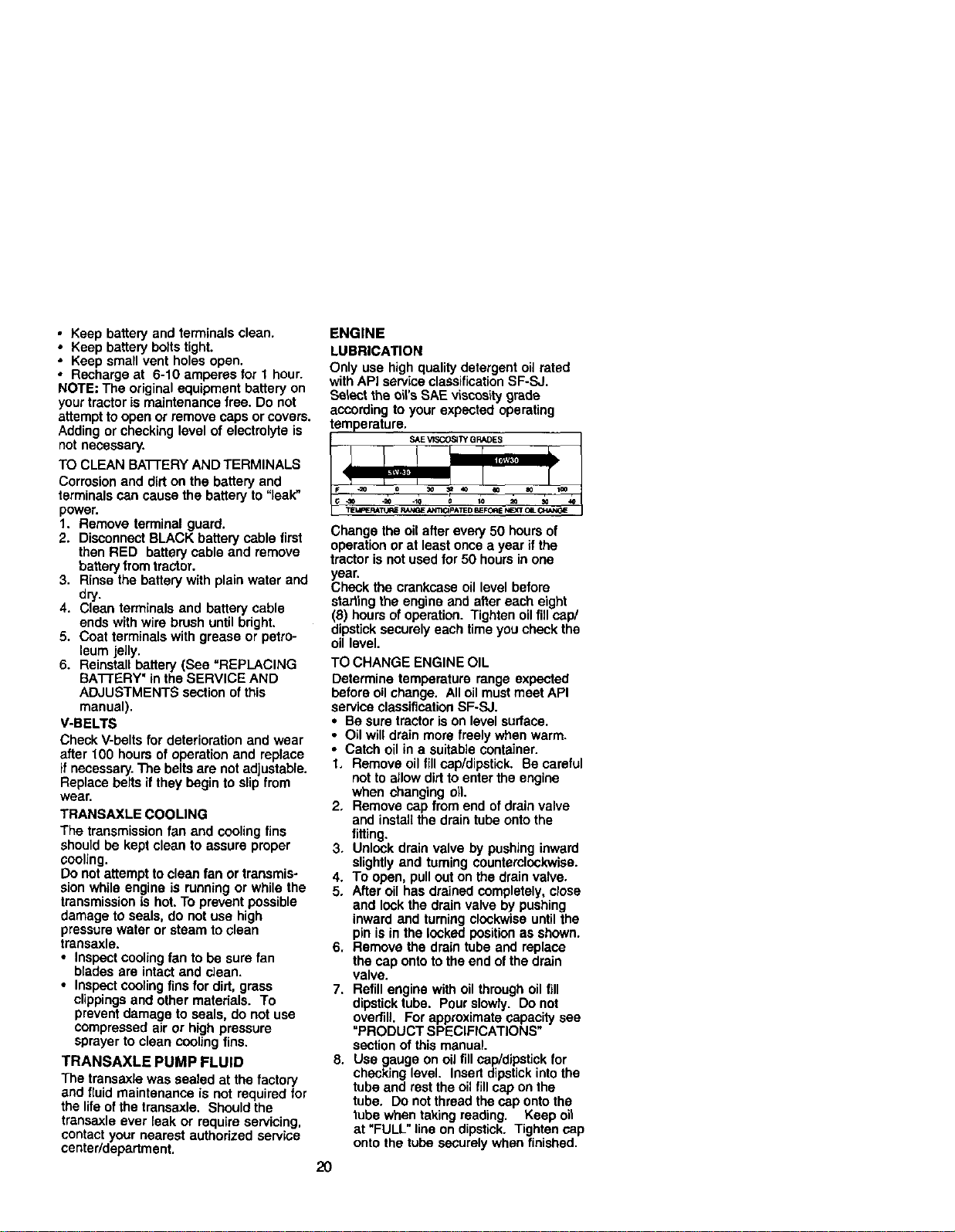
Oil Drain Valve
Cap /
DrainTube
CLEAN AIR SCREEN
Air screen must be kept free of dirt and
chaff to prevent engine damage from
overheating. Clean with a wire brush or
compressed air to remove did and
stubborndried gum fibers.
CLEAN AIR INTAKE/COOLING AREAS
To insure proper cooling, make sure the
grass screen, cooling fins, and other
external surfaces of the engine are kept
clean at all times.
Every 100 hours of operalion (more o_en
under extremely dusty, dirty conditions),
remove the blower housing and other
coolingshrouds. Clean the cooling fins
and external surfaces as necessary. Make
sure the cooling shrouds are reinstalled.
NOTE: Operating the engine with a
blocked grass screen, dirty or p}ugged
coolingfins, and/or cooling shrouds
removed wit{ cause engine damage due
to overheating.
AIR FILTER
Your engine will not run properly using a
dirty airfitler. Clean the foam pre-cleaner
after every 25 hours of operation or every
season. Service paper cartridge every
100 hours of operation or every season,
whichever occurs first.
Service air cleaner more often under
dusty conditions.
1. Loosen knob and remove cover.
TO SERVICE PRE-CLEANER
2. Slide foam pre-cleaner off cartridge.
3. Wash it in liquiddetergent and water.
4. Squeeze it dry in a clean cloth. Allow
itto dry.
5. Saturale i'iin engine oil Wrap it in
clean, absorbent cloth and squeeze to
remove excess oil.
TO SERVICE CARTRIDGE
• Replace a dirty, bent, or damaged
cartridge.
ENGINE OIL FILTER
Replace the engine oil filter every season
or every other oil change if the tractor is
used more than 100 hours in one year.
MUFFLER
Inspect and replace corroded muffler and
spark arrester (if equipped) as it could
create a fire hazard and/or damage.
SPARK PLUGS
Replace spark plugs at the beginning of
each mowing season or after every 100
hours of operation, wh_.hever occurs first.
Spark plug type and gap setting are
shown in "PRODUCT SPECIFICATIONS"
section of this manual.
IN-LINE FUEL FILTER
The fuel filter should be replaced once
each season. If fuel filter becomes
clogged, obstructingfuel flow to carbure-
tor, rep{acement is required.
1. With engine cool, remove filter and
plug fuel line sections.
2. Place new fuel filter in positionin fuel
line with arrow pointingtowards
carburetor.
3. Be sure there are no fuel line leaks
and clamps are properly positioned.
4. Immediately wipe up any spilled
gasoline.
Clamp
FuelFilter_
NOTE: Do not wash the paper cartridge
or use pressurized air, as this will
damage the cartridge.
6. Remove nutand cartridge plate.
7. Reinstall the pre-cleaner (cleaned
and oiled) over the paper cartridge,
8. Check rubber seal for damage and
proper position around stud. Replace
if necessary.
9. Reassemble air cleaner, cartridge
plate, and nut.
10.Reinstall air cleaner cover and secure
by tightening knob.
Foam
Cartridge
Rubber
Seal
21
CLEANING
• Clean engine, battery, seat, finish, etc.
of all foreign matter.
• Keep finished surfaces and wheels free
of all gasoline, oil, etc.
• Protect painted surfeces with automo-
tive type wax.
We do not recommend usinga garden
hose to clean your tractor unless the
electrical system, muffler,air filterand
carburetor are covered to keep water out.
Water in engine can result in a shortened
engine life.
CAUTION: BEFORE PERFORMING ANY SERVICE OR ADJUSTMENTS:
brake pedal fully and set parking brake.
2. Place attachment clutch in =DISENGAGED" position.
3. Turn ignition key =OFF_ and remove key.
4, Make sure the blades and all moving pads have completely stopped.
5. Disconnect spark plug wire from spark plug and place wire where it cannot
come in contact with plug.
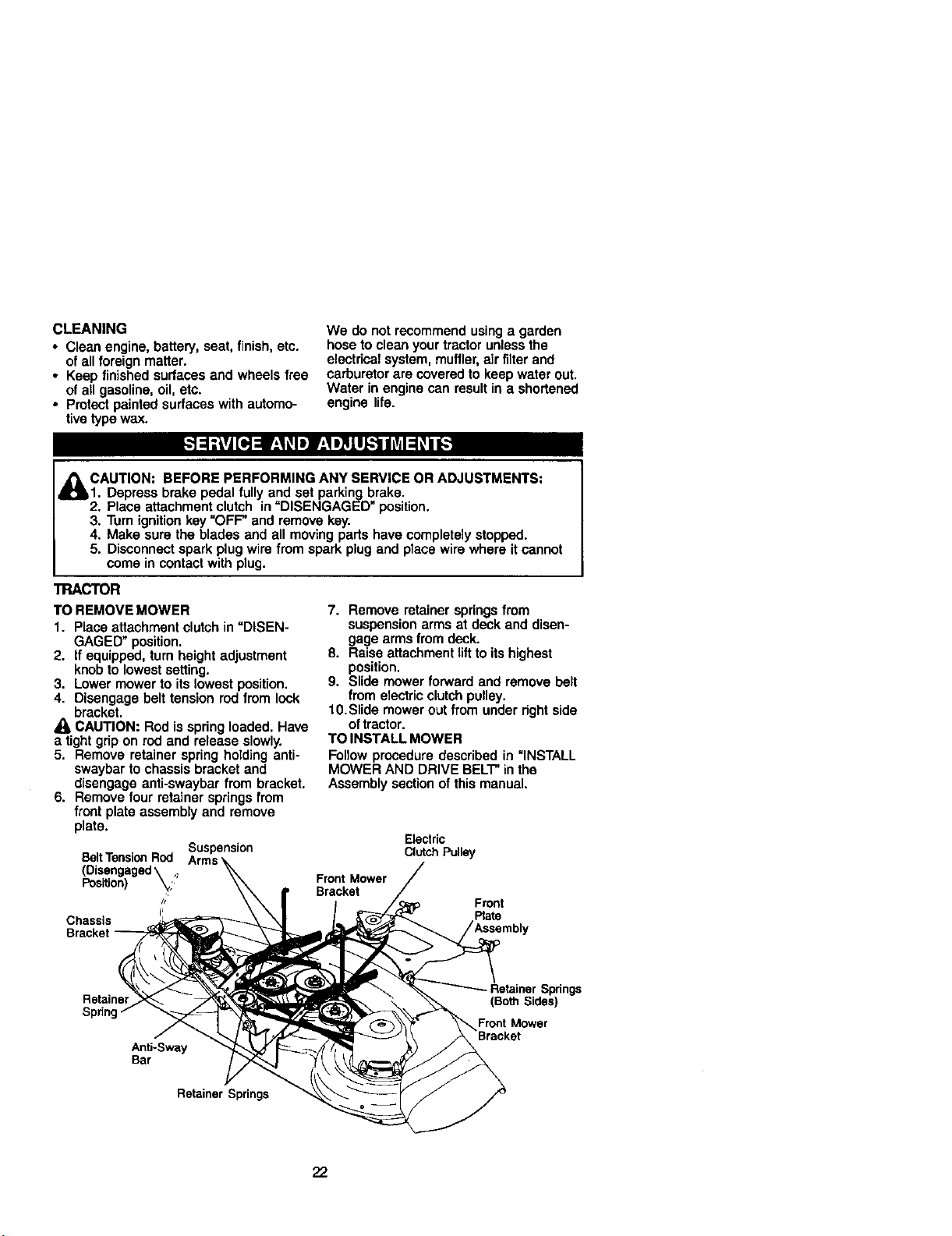
TRACTOR
TO REMOVE MOWER
1. Place attachment clutch in "DISEN-
GAGED" position.
2. If equipped, turn height adjustment
knob to lowest setting.
3. Lower mower to its lowest position.
4. Disengage belt tension rod from lock
bracket.
CAUTION: Rod isspring loaded. Have
a tight grip on rod and release slowly.
5. Remove retainer spring holding anti-
swaybar to chassis bracket and
disengage anti-swaybar from bracket.
6. Remove four retainer springs from
front plate assembly and remove
plate.
Suspension
BeltTensionRod
(Disengaged\ ,.
Position) _'
Chassis
7. Remove retainer springsfrom
suspension arms at deck and disen-
gage arms from deck.
8. Raise attachment riftto its highest
position.
9. Slide mower forward and remove belt
from electric clutch pulley.
1O.Slide mower out from under right side
oftractor.
TO INSTALL MOWER
Follow procedure described in =INSTALL
MOWER AND DRIVE BELT"inthe
Assembly section of this manual.
Electric
Clutch Pulley
Front Mower
Bracket
Front
Plate
Retainer
Anti-Sway
Bar
Retainer Springs
Retainer Springs
(Bo_ Sides)
_Front Mower
Bracket
22
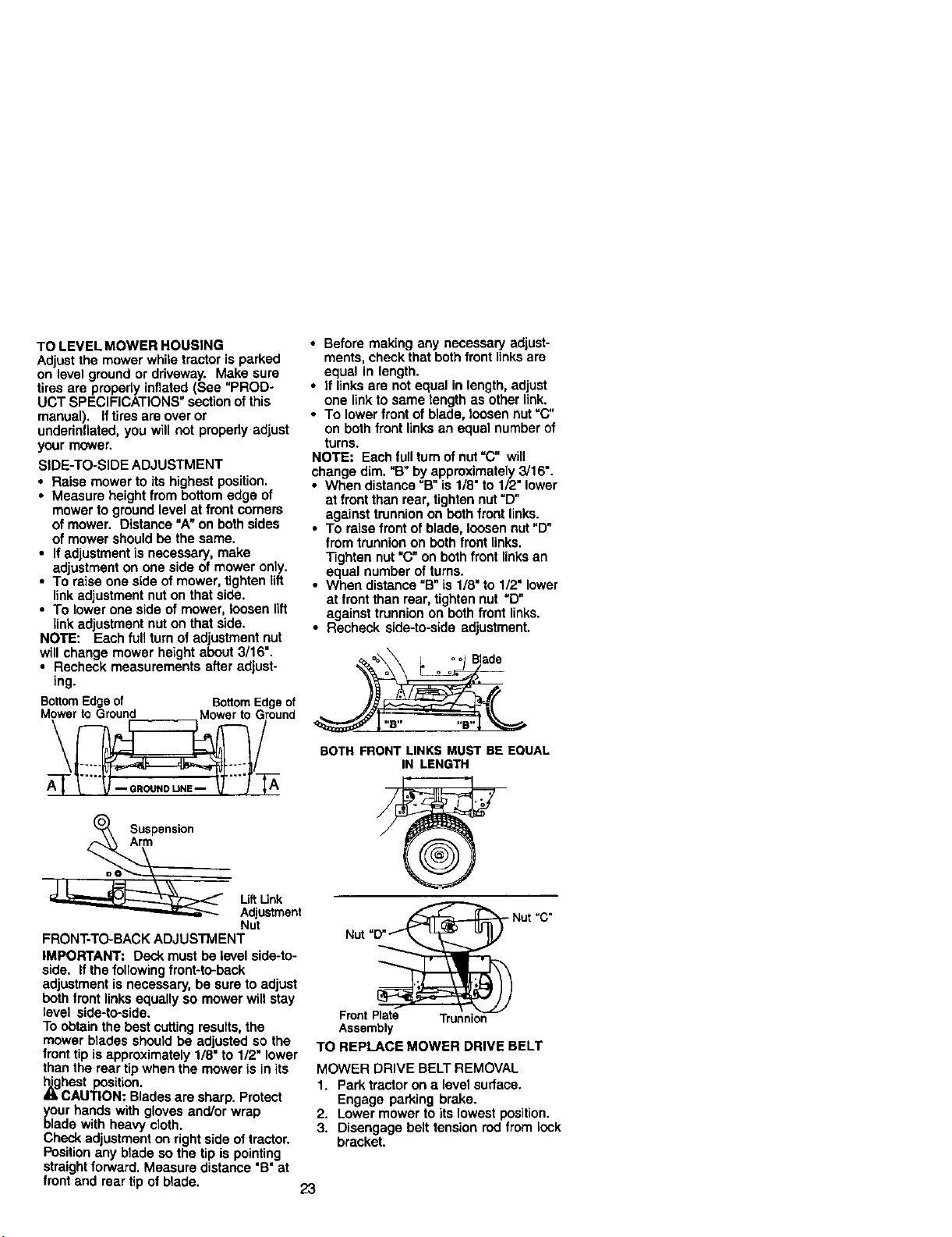
TO LEVEL MOWER HOUSING
Adjust the mower while tractor is parked
on level ground or driveway. Make sure
tires are properly inflated (See "PROD-
UCT SPECIFICATIONS" section ofthis
manual). Iftirosare over or
underinfiated, you will not propedy adjust
your mower.
SIDE-TO-SIDE ADJUSTMENT
• Raise mower to its highest position.
• Measure height from bottom edge of
mower to groundlevel at front corners
of mower. Distance "A" on both sides
of mower should be the same.
• If adjustment is necessary, make
adjustment on one side of mower only.
• To raise one side of mower, tighten lift
linkadjustment nuton that side.
• To lower one side of mower, loosen lift
link adjustment nuton that side.
NOTE: Each full turn of adjustment nut
will change mower height about 3/16".
• Recheck measurements after adjust-
ing.
BottomEdgeof BottomEdgeof
Mowerto Ground Mower to Ground
\ /
(_ Suspension
Arm
Uft Link
Adjustment
Nut
FRONT-TO-BACK ADJUSTMENT
IMPORTANT: Deck must be level side-to-
side. If the followingfront-to-back
adjustment is necessary, be sure to adjust
both front links equally so mower will stay
level side-to-side.
To obtain the best cuttingresults, the
mower blades should be adjusted so the
front tip is approximately 1/8" to 1/2" lower
than the roar tip when the mower is in its
_hest position.
CAUTION: Blades are sharp. Protect
your hands with gloves and/or wrap
blade with heavy cloth.
Check adjustment on right side of tractor.
Positionany blade so the tip is pointing
straight forward. Measure distance "B" at
front and roartip of blade.
• Before making any necessary adjust-
ments, check that both front linksare
equal in length.
• If links are not equal in length, adjust
one link to same length as other link.
• To lower front of blade, loosen nut "C"
on both front ILnksan equal number of
turns.
NOTE: Each full turnof nut "C" will
change dim. "B" by approximately 3/16".
• When distance "B" is 1/8" to 1/2" lower
at front than rear, tighten nut"D"
against trunnionon both front links.
• To raise front of blade, loosen nut "D"
from trunnion on both front links.
Tighten nut "C" on both front linksan
equal number of turns.
• When distance "B" is 1/8"to 1/2" lower
at front than roar, tighten nut "D"
against trunnion on both front links.
• Recheck side-to-side adjustment.
BOTH FRONT LINKS MUST BE EQUAL
IN LENGTH
Front Plate Trunnion
Assembly
TO REPLACE MOWER DRIVE BELT
MOWER DRIVE BELT REMOVAL
1. Park tractor on a level surface.
Engage parking brake.
2. Lower mower to its lowest position.
3. Disengage belt tension rod from lock
bracket.
23
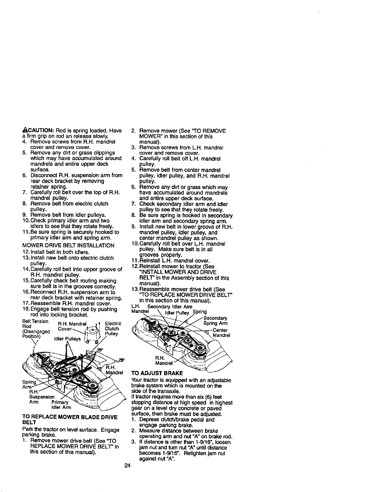
_,CAUTION: Rod is spring loaded. Have
a firm grip on rod an release slowly.
4. Remove screws from R.H. mandrel
cover and remove cover,
5. Remove any dirt or grass clippings
which may have accumulated around
mandrels and entire upper deck
surface.
6. Disconnect R.H. suspension arm from
rear deck bracket by removing
retainer spring.
7. Carefully roll belt over the top of R.H.
mandrel pulley.
8. Remove belt from electdc clutch
pulley.
9. Remove belt from idler pulleys.
10.Check primary idler arm and two
idlersto see that they rotate freely.
11, Be sure spring is securely hooked to
primary idler arm and spring arm.
MOWER DRIVE BELT INSTALLATION
12.thstall belt inboth idlers.
13. Install new belt onto electric clutch
pulley.
14.Carefully roll belt Into upper groove of
R.H. maodral pulley.
15.Carefully check belt muting making
sure belt is in the grooves correctly.
16. Reconnect R.H. suspension arm to
rear deck bracket with retainer spring.
17. Reassemble R.H, mandrel cover.
18.Engage belt tension rod by pushing
rod into locking bracket.
BeltTension R.H. Mandrel Electric
Rod
(Disengaged Cover_ Clutch
Posi_n)
Mandrel
Suspension
Arm Primary
Idler Arm
TO REPLACE MOWER BLADE DRIVE
BELT
Park the tractoron level surface. Engage
parkingbrake.
1. Remove mower drive belt (See "TO
REPLACE MOWER DRIVE BELT" in
this section of this manual).
2. Remove mower (See "TO REMOVE
MOWER" in this section of this
manual).
3. Remove screws from L.H. mandrel
cover and remove cover.
4. Carefully roll belt off L.H. mandrel
pulley.
5. Remove belt from center mandrel
pulley, idler pulley, and R.H. mandrel
pulley.
6. Remove any dirt or grass which may
have accumulated around mandrels
and entire upper deck surface.
7. Check secondary idler arm end idler
pulley to sea that they rotate freely.
8. Be sure spring is hooked in secondary
idler arm and secondary spring arm.
9. Install new belt in lower groove of R.H.
mandrel pulley, idler pulley, and
center mandrel pulley as shown.
10.Carefully roll belt over L.H. mandrel
pulley. Make sure belt is in all
grooves properly.
11. Reinstall L.H. mandrel cover.
12. Reinstall mower to tractor (See
"INSTALL MOWER AND DRIVE
BELT" in the Assembly section of this
manual),
13.Reassemble mower drive belt (See
"TO REPLACE MOWER DRIVE BELT"
in this section of this manual).
L.H. SecondaryIdlerArm
_ IdlerPulley Sprlng
_f" /Secondary
SpnngArm
._'_Canter
R.H_
Mandrel"
TO ADJUST BRAKE
Your tractor is equipped with an adjustable
brake system which is mounted on the
side ol the transaxle.
If tractorrequires morethan six (6) feet
stoppingdistance at highspeed in highest
gear on a level dryconcrete or paved
surface, then brake must be adjusted.
1. Depress clutch/brakepedal and
engage parking brake.
2. Measure distance between brake
operatingarm and nut "A"on brake rod.
3. If distanceis other than 1-9/16", loosen
jam nut and turn nut "A"untildistance
becomes 1-9/16". Retightenjam nut
against nut "A".
24
4. Road test tractorfor proper stopping
distance as stated above. Readjust if
necessary. If stoppingdistance isstill
greater than six (6) feet in highest gear,
further maintenance is necessary.
Contact a Sears or other qualified
service center.
Wlth Perking Brake "Engaged"
m Nut
._OOperating
Arm
DoNottouchthis nut. Iffurtherbrake
adjustmentis necessarycontacta Searsor
otherqualifiedservicecenter.
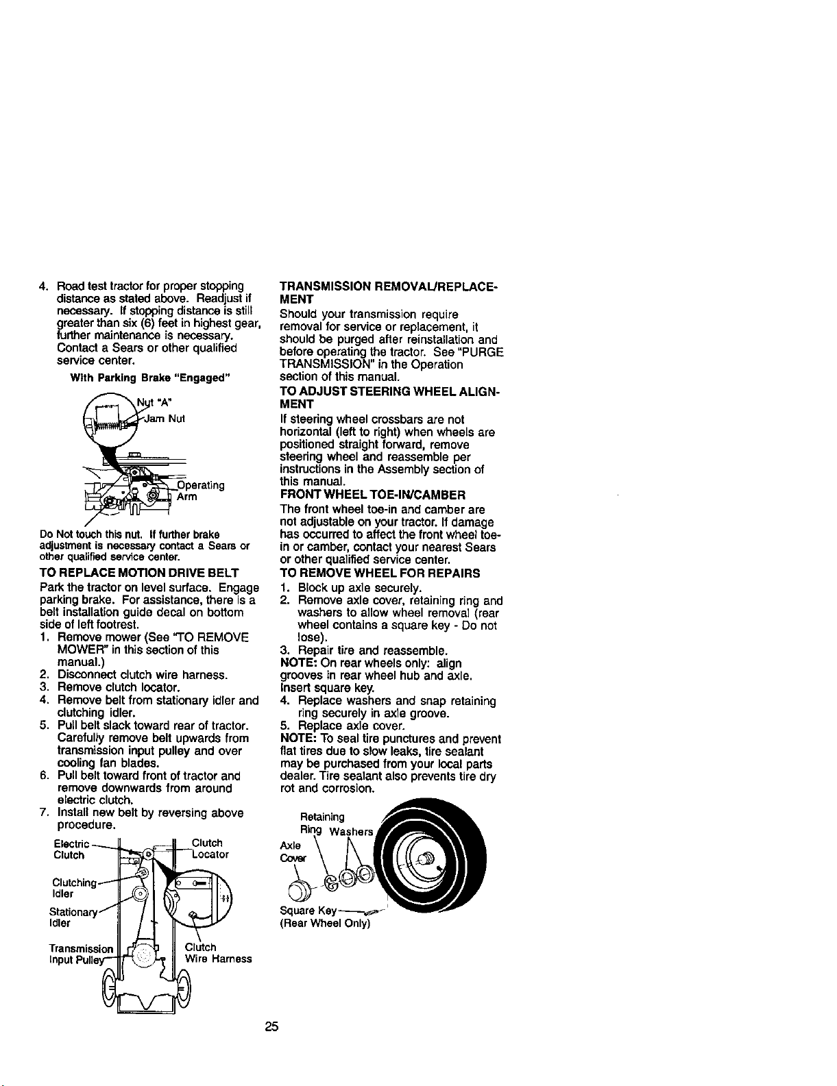
TO REPLACE MOTION DRIVE BELT
Park the tractor on level surface. Engage
parkingbrake. For assistance, there isa
belt installation guide decal on bottom
side of left footrest.
1. Remove mower (Sea "TO REMOVE
MOWER" in thissection of this
manual.)
2. Disconnect clutch wire harness.
3. Remove clutch Iocator.
4. Remove bolt from stationary idler and
clutching idler.
5. Pull belt slack toward rear of tractor.
Carefully remove belt upwards from
transmission input pulley and over
cooling fan blades.
6. Pull belt toward front oftractor and
remove downwards from around
electric clutch.
7. Install new belt by reversing above
procedure.
Electric_ _
Clutch
Clutching_
Idler
Stationaryj
Idler
Transmission
InputPulley-"
Clutch
--Locator
Clutch
Wire Harness
TRANSMISSION REMOVAL/REPLACE-
MENT
Should your transmission require
removal for service or replacement, it
should be purged after reinstallationand
before operating the tractor. See "PURGE
TRANSMISSION" in the Operation
section of this manual.
TO ADJUST STEERING WHEEL ALIGN-
MENT
If steering wheel crossbars are not
horizontal (left to right) when wheels are
positioned straight forward, remove
steering wheel and reassemble per
instructionsin the Assembly section of
this manual.
FRONT WHEEL TOE-IN/CAMBER
The front wheel toe-in and camber are
notadjustable on your tractor. If damage
has occurred to affect the front wheel toe-
in or camber, contact your nearest Sears
or other qualified service center.
TO REMOVE WHEEL FOR REPAIRS
1. Block up axle securely.
2. Remove axle cover, retaining ring and
washers to allow wheel removal (rear
wheel contains a square key - Do not
lose).
3. Repair tire and reassemble.
NOTE: On rear wheels only: align
grooves in rear wheel hub and axle.
Insert square key.
4. Replace washers and snap retaining
ring securely in axle groove.
5. Replace axle cover.
NOTE: To seal tire punctures and prevent
flat tires due to slow leaks, tire sealant
may be purchased from your local parts
dealer. Tire sealant also prevents tire dry
rot and corrosion.
Retaining
Washers
Axle
Cover
Square Key_,_"
(Rear Wheel Only)
25
TO START ENGINE WITH A WEAK
BATrERY
_,CAUTION: Lead-acid batteries
generate explosive gases. Keep sparks,
flame and smoking materials away from
battedas. Always wear eye protection
when around batteries.
ff your battery istoo weak to start the
engine, it should be recharged. (See
"BA'I-rERY"in the MAINTENANCE
section of this manuat).
If "jumper cables" are used for emergency
starting, follow this procedure:
IMPORTANT: Your tractor is equipped
with a 12 volt negative grounded system.
The other vehical must also be a 12 volt
negative grounded system. Do not use
your tractor batteryto start other vehicles.
TO ATI'ACHJUMPER CABLES-
1. Connect each end of the RED cable to
the POSITIVE (+) terminal ofeach
battery, taking care not to short
against chassis.
2. Connect one end of the BLACK cable
to the NEGATIVE (-) terminal of fully
charged battery.
3. Connect the other end of the BLACK
cable to good CHASSIS GROUND,
away from fuel tank and battery.
TO REMOVECABLES, REVERSE ORDER -
1. BLACK cable firstfrom chassisand
then fromthe fully charged battery.
2. RED cable last from both battedas.
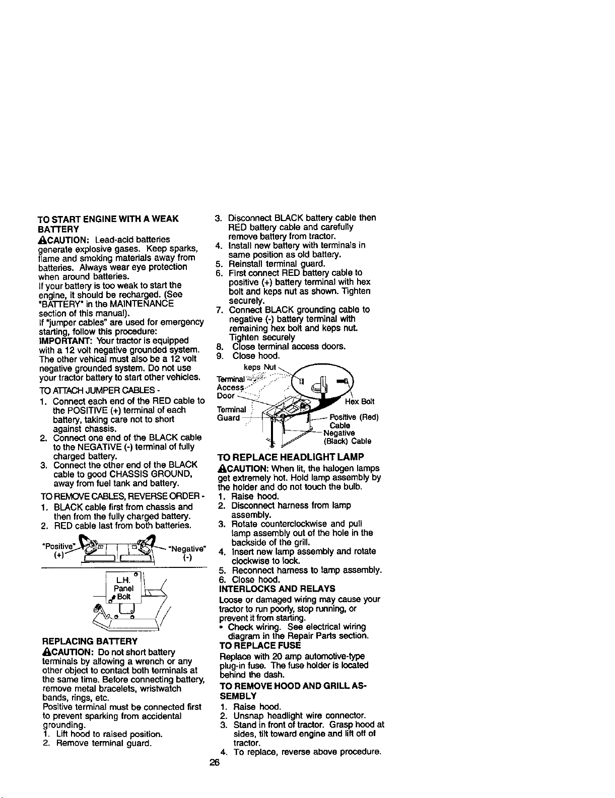
(.)
"Po(si_ve" "Negative"
REPLACING BAI-I'ERY
_,CAUTION: Do not short battery
terminals by allowing a wrench or any
other object tocontact both terminals at
the same time. Before connecting battery,
remove metal bracelets, wristwatch
bands, rings,etc.
Positiveterminal must be connected first
to prevent sparking from accidental
grounding.
1, Lift hood to raised position.
2. Remove terminal guard.
3. Disconnect BLACK battery cable then
RED battery cable and carefully
remove battery from tractor.
4. Install new battery with terminals in
same position as old battery.
5. Reinstall terminal guard.
6. First connect RED battery cable to
positive (+) battery terminal with hex
bolt and keps nut as shown. "13ghten
securely.
7. Connect BLACK grounding cable to
negative (-) battery terminal with
remaining hex bolt and keps nut.
Tighten securely
8. Close terminal access doors,
9. Close hood.
keps.Nut_
Access..'" ..'" .'
Door_"" -: xBolt
Terminal
Guard_-_i_ - _ Positive(Red)
-_ Cable
Negative
(Black)Cable
TO REPLACE HEADLIGHT LAMP
_,CAUTION: When lit,the halogen lamps
get extremely hot. Hold lamp assembly by
the holder and do not touch the bulb.
1. Raise hood.
2. Disconnect harness from lamp
assembly.
3. Rotate counterclockwise and pull
lamp assembly out of the hole in the
backside of the grill.
4. Insert new lamp assembly and rotate
clockwise to lock.
5. Reconnect harness to tamp assembly.
6. Close hood.
INTERLOCKS AND RELAYS
Loose or damaged wiring may cause your
tractorto run poorly,stoprunning,or
prevent itfrom starting.
• Check wiring. See electrical wiring
diagram in the Repair Pads section.
TO REPLACE FUSE
Replace with 20 amp automotive-type
plug-infuse. The fuse holderis Iccated
behind the dash.
TO REMOVE HOOD AND GRILL AS-
SEMBLY
1. Raise hood.
2. Unsnap headlight wire connector.
3. Stand in frontof tractor. Grasp hood at
sides, tilttoward engine and liftoff ot
tractor.
4. To replace, reverse above procedure.
26
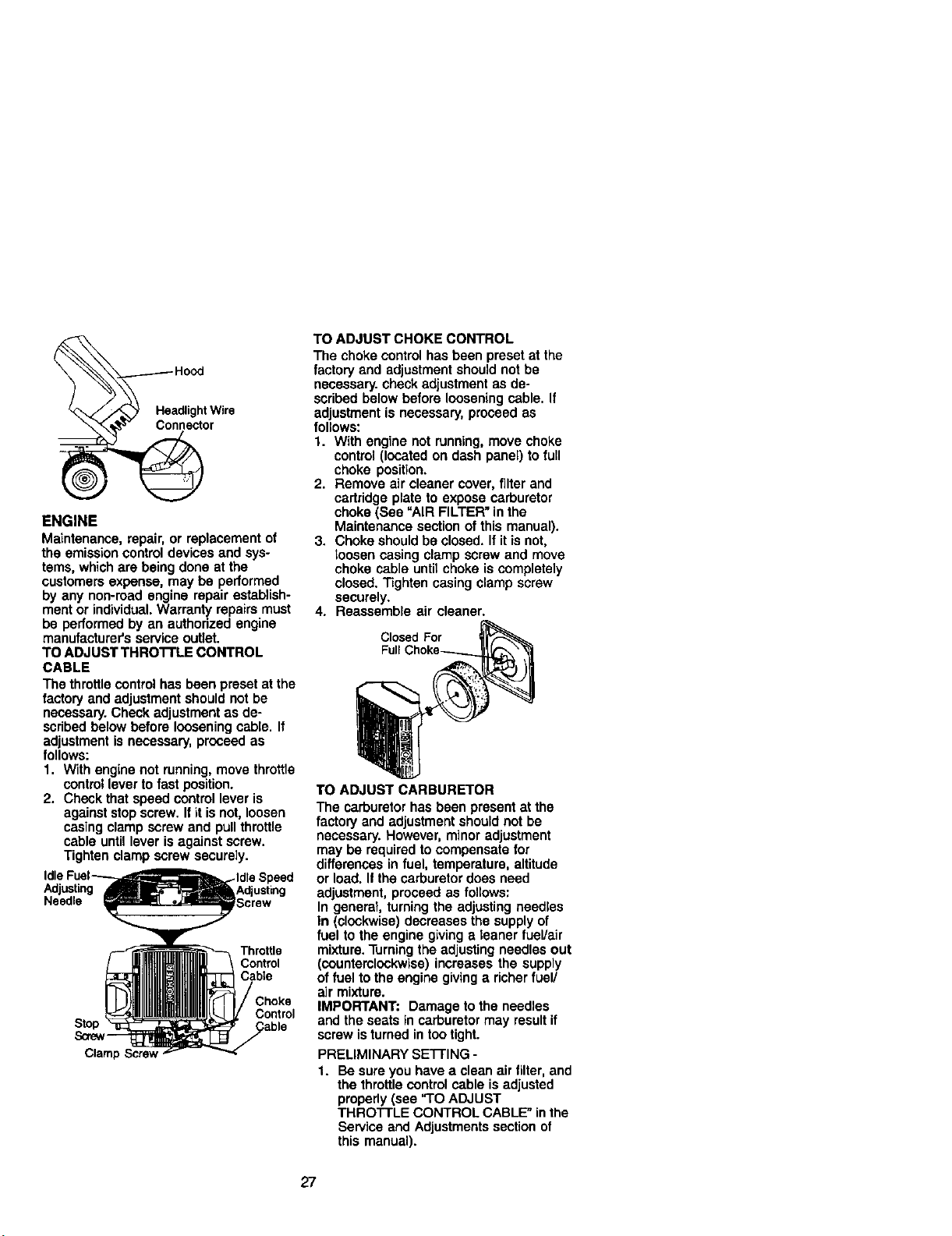
ENGINE
Maintenance,repair, or replacement of
the emission control devices and sys-
tems, which are being done at the
customersexpense, may be performed
by any non-road engine repair establish-
ment or individual.Warranty repairs must
be performed by an authorized engine
manufacturer's service outlet.
TO ADJUST THRO'I'rLE CONTROL
CABLE
The throttlecontrol has been preset at the
factory and adjustment should not be
necessary. Check adjustment as de-
scribed below before loosening cable. If
adjustment is necessary, proceed as
follows:
1. With engine not running, move throttle
control lever to fast position.
2. Check that speed control lever is
against stop screw. Ifit isnot, loosen
casing clamp screw and pull throttle
cable until lever is against screw.
Tighten clamp screw securely.
Adjusting
Needle
Throttle
Control
Cable
Stop
Sa'e_
Clarn_
Control
TO ADJUST CHOKE CONTROL
The choke control has been preset at the
factory and adjustment should not be
necessary, check adjustment as de-
scribed below before loosening cable. If
adjustment is necessary, proceed as
follows:
1. With engine not running, move choke
control (located on dash panel) to full
choke position.
2. Remove air cleaner cover, filter and
cartridge plate to expose carburetor
choke (See "AIR FILTER" in the
Maintenance section of this manual).
3. Choke should be closed. If it is not,
loosen casing clamp screw and move
choke cable until choke is completely
closed. Tighten casing clamp screw
securely.
4. Reassemble air cleaner.
Closed For
Full
TO ADJUST CARBURETOR
The carburetor has been present at the
factory and adjustment should not be
necessary. However, minor adjustment
may be required to compensate for
differences in fuel, temperature, altitude
or load. If the carburetor does need
adjustment, proceed as follows:
In general, turningthe adjusting needles
In (clockwise) decreases the supply of
fuel to the engine giving a leaner fuel/air
mixture. Turningthe adjusting needles out
(countemlockwise) increases the supply
of fuel to the engine givinga richer fuel/
air mixture.
IMPORTANT: Damage to the needles
and the seats in carburetor may result if
screw isturned in too tight.
PRELIMINARY SE'I-rlNG -
1. Be sure you have a clean air filter, and
the throttle control cable is adjusted
properly (see "TO ADJUST
THROTTLE CONTROL CABLE" in the
Service and Adjustments section of
this manual).
27
2. With engine off turn idle fuel adjusting
needle In (clockwise) closing it finger
tight and then turn out (counterclock-
wise) 1 turn.
FINAL SETTING -
1. Start engine and allow to warm for five
minutes. Make final adjustments with
engine running and shift/motion
control lever in neutral (N) position.
NOTE: The highidle isset at the factory
and cannot be adjusted.
2. Idle soeed settino - With throttle
control lever in slow position, engine
should idle at 1200 RPM. If engine
idles too slow or fast, turn idle speed
adjusting screw in or out untilcorrect
idle is attained.
3. IU!9fuel needle settino - With throttle
control lever in slow position, turn idle
fuel adjusting needle In (clockwise)
until engine speed decreases and
then turn out (counterclockwise)
approximately 3/4 turn to obtain the
best low speed performance.
4. Recheck idle speed. Readjust if
necessary.
ACCELERATION TEST -
5. Move throttle control leverfrom slowto
fast position. If engine hesitates or
dies, turn idle fuel adjusting needle
out (counterclockwise) 1/8 turn.
Repeat test and continue to adjust, if
necessary, until engine accelerates
smoothly.
High speed stop is factory adjusted. Do
not adjust-damage may result.
IMPORTANT: Never tamper with the
engine governor, which is factory set for
proper engine speed. Overspoeding the
engine above the factory high speed
setting can be dangerous. If you think the
engine-governed high speed needs
adjusting, contactyour nearest Sears or
other qualified service center, which has
proper equipment and experience to
make any necessary adjustments.
28
Immediately prepare your tractor for
storage at the end of the season or if the
tractor will notbe used for 30 days or
more.
•,CAUTION: Never store the tractor with
gasoline in the tank inside a building
where fumes may reach an open flame or
spark. Allow the engine to coolbefore
storing in any enclosure.
TRACTOR
Remove mower from tractorlor winter
storage. When mower isto be stored for
e period of time, clean it thoroughly,
remove all dirt, grease, leaves, etc. Store
in a clean, dry area.
1. Clean entire tractor (See "CLEANING"
in the Maintenance section of this
manual).
2. Inspect and replace belts, if necessary
(See belt replacement instructionsin
the Service and Adjustments section
of this manual).
3. Lubricate as shown in the Mainte-
nance section of this manual
4. Be sure that all nuts, bolts and screws
are securelyfastened. Inspect moving
parts for damage, breakage and wear.
Replace if necessary.
5. Touch up all rusted or chipped paint
surfaces; sand lightlybefore painting.
BA'rFERY
• Fullycharge the battery for storage
• After a period oftime in storage, battery
may require recharging.
• To help prevent corrosionand power
leakage during long periods of storage,
battery cables should be disconnected
and battery cleaned thoroughly (see
"TO CLEAN BA'I-rERY AND TERMI-
NALS" in the Maintenance section of
this manual).
• After cleaning, leave cables discon-
nected and place cables where they
cannot come in contact with battery
terminals.
• If battery is removed from tractor for
storage, do not store battery directly on
concrete or damp surfaces.
ENGINE
FUEL SYSTEM
IMPORTANT: It isimportant to prevent
gum deposites from forming in essential
fuel system parts such as carburetor, fuel
hose, or tank during storage. Also,
experience indicates that alcohol
blended fuels (called gasohol or using
ethanol or methanol) can attract moisture
which leads to separation and formation
of acids during storage. Acidic gas can
damage the luel system of and engine
while in storage.
1. Drain the fuel tank.
2. Start the engine end let it run until the
fuel lines and carburetor are empty.
• Never use engine or carburetor cleaner
products in the fuel tank or permanent
damage may occur.
• Use fresh fuel next season.
NOTE: Fuel stabilizer is an acceptable
alternative in minimizing the formation of
fuel gum deposits during storage. Add
stabilizer to gasoline in fuel tank or
storage container. Always follow the mix
ratio found on stabilizer container. Run
engine at least 10 minutes after adding
stabilizer to allow the stabilizer to reach
the carburetor. Do not drain the gas tank
and carburetor if using fuel stabilizer.
ENGINEOIL
Drain oil (with engine warm) and replace
with clean engine oil (See "ENGINE" in
the Maintenance section of this manual).
CYLINDER(S)
t. Remove spark plug(s).
2. Pour one ounce of oil through spark
plug hole(s) into cylinder(s).
3. Turn ignitionkey to "START" position
for a few secondsto distributeoil.
4. Replace with new spark plug(s).
OTHER
• Do not store gasoline from one season
to another.
• Replace your gasoline can if your can
starts to rust. Rust and/or dirt inyour
gasoline will cause problems
• If possible, storeyour tractor indoors
and cover itto give protectionfrom dust
and dirt.
• Cover your tractor with a suitable
protective cover that does not retain
moisture. Do not use plastic. Plastic
cannot breathe which allows conden-
sation to form and will cause your
tractor to rust.
IMPORTANT: Never cover tractor while
engine and exhaust areas are still warm.
29
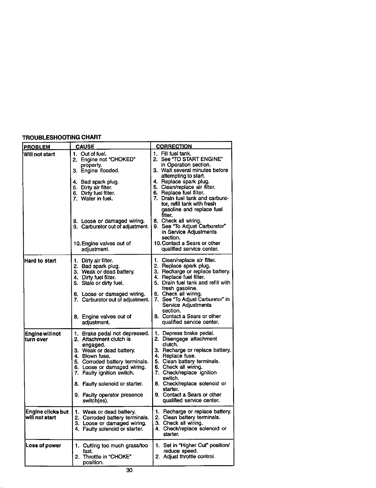
TROUBLESHOOTING CHART
PROBLEM CAUSE
Will not start 1, Out _ fuel
2.
3.
4.
5.
6.
7.
8.
9.
Hard to Start
Englnewill not
turn over
Engine not "CHOKED"
properly.
Engine flooded.
Bad spark plug.
Dirty air filter.
Dirty fuel filter.
Water in fuel.
Loose or damaged wiring.
Carburetor out of adjustment,
10.Engine valves out of
adjustment.
1. Dirty air filter.
2. Bad spark plug.
3. Weak or dead battery.
4. Dirty fuel filter.
5. Stale or dirty fuel.
6. Loose or damaged wiring.
7. Carburetor out ofadjustment.
8. Enginevalvesoutof
adjustment.
1. Brake pedal not depressed.
2. Attachment clutchis
engaged.
3. Weak or dead battery.
4, Blown fuse.
5. Corroded battery terminals.
6. Loose or damaged wiring.
7. Faulty ignition switch.
8, Faultysolenoid or starter.
(_0RRECTION
1. Fill fuel tank,
2. See "TO START ENGINE"
in Operation section.
3. Wait several minutes before
attempting to start.
4. Replace spark plug.
5. Clean/replece air filter.
6. Replace fuel filter.
7. Drain fuel tank and carbure-
tor, refilltank with fresh
gasoline end replace fuel
filter.
8. Check all wiring.
9. See "To Adjust Carburetor"
in Service Adjustments
section.
1O.Contact a Sears or other
qualified service center.
1. Clean/replace air filter.
2. Replace spark plug.
3. Recharge or replace battery.
4. Replace fuel filter.
5. Drain fuel tank and refill with
fresh gasoline.
6. Check all wiring.
7. See "To Adjust Carburetor" in
Service Adjustments
section.
8. Contact a Sears or other
qualified service center.
1. Depress brake pedal.
2. Disengage attachment
clutch,
3. Recharge or replace battery.
4. Replace fuse.
5. Clean battery terminals.
6. Check all wiring.
i 7. Check/replace ignition
switch.
8. Check/replace solenoid or
starter.
9. Contact a Sears or other
qualified service center.
9. Faulty operator presence
switch(as).
5nglne clicks but 1. Weak or dead battery. 1. Recharge or replace battery.
t_lll not start 2. Corroded battery terminals. 2. Clean battery terminals.
3. Loose or damaged wiring. 3. Check all wiring.
4. Faultysolenoid or starter. 4. Check/replace solenoid or
starter.
,oss of power 1. Cuttingtoo much grass/too 1. Set in =Higher Cut" position/
fast. reduce speed.
2. Throttle in "CHOKE" 2. Adjustthrottle control.
position.
3O
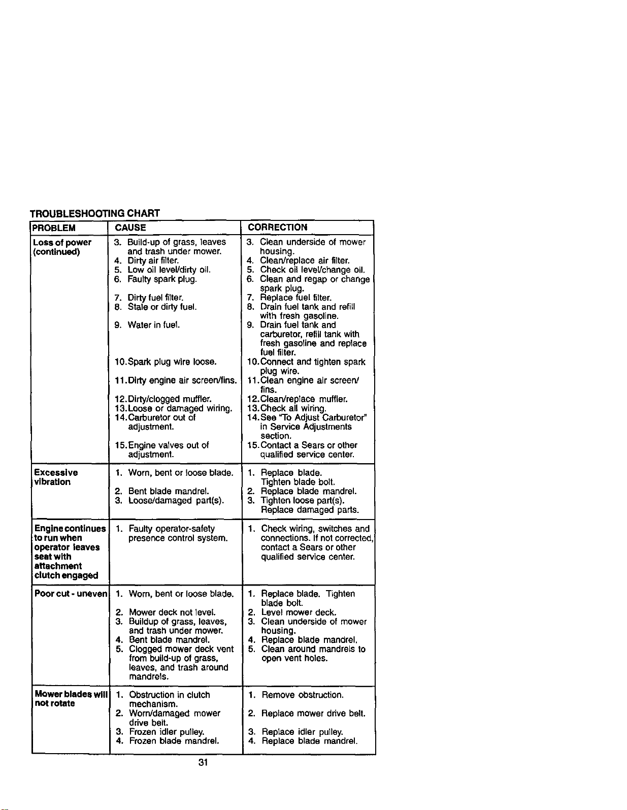
TROUBLESHOOTINGCHART
PROBLEM
Lossofpower
(continued)
Excessive
vibration
CAUSE
3. Build-upof grass, leaves
and trash under mower.
Engine continues
to run when
operator leaves
seat with
attachment
clutch engaged
Poor cut-uneven
Mower blades will
not rotate
4. Didy air filter.
5. Low oil level/dirty oil.
6. Faulty spark plug.
7. Dirty fuel filter.
8. Stale or dirty fuel.
9. Water in fuel
10.Spark plug wire loose.
11. Dirty engine air screenffins.
12. Dirty/clogged muffler.
13.Loose or damaged wiring.
14. Carburetor out of
adjustment.
15.Engine valves out of
adjustment.
1. Worn, bent or loose blade.
2. Bent blade mandrel.
3. Loose/damaged part(s).
1. Faulty operator-safety
presence control system.
1. Worn, bent or loose blade.
2. Mower deck not level.
3. Buildup of grass, leaves,
and trash under mower.
4. Bent blade mandrel.
5. Clogged mower deck vent
from build-up of grass,
leaves, and trash around
mandrels.
1. Obstruction in clutch
mechanism.
2. Worn/damaged mower
drive belt.
3. Frozen idler pulley.
4. Frozen blade mandrel.
CORRECTION
3. Clean underside of mower
housing.
4. Clean/replace air filter.
5. Check oil leveVchange oil.
6. Clean and regap or change
spark plug.
7. Replace fuel filter.
8. Drain fuel tank and refill
with fresh gasoline.
9. Drain fuel tank and
carburetor, refill tank with
fresh gasoline and replace
fuel filter.
1O.Connect and tighten spark
plug wire.
11.Clean engine air screen/
fins.
12.Clean/replace muffler.
13.Check all wiring.
14. See "To Adjust Carburetor"
in Service Adjustments
section.
15.Contect e Sears or other
qualified service center.
1. Replace blade.
Tighten blade bolt.
2. Replace blade mandrel.
3. Tighten loose part(s).
Replace damaged pads.
1. Check wiring, switches and
connections. If not corrected
contact a Sears or other
qualified service center.
1. Replace blade. Tighten
blade bolt.
I 2. Level mower deck.
3. Clean underside of mower
housing.
4. Replace blade mandrel.
5. Clean around mandrels to
open vent holes.
1. Remove obstruction.
! 2. Replace mower drive belt.
3. Replace idler pulley.
4. Replace blade mandrel.
31
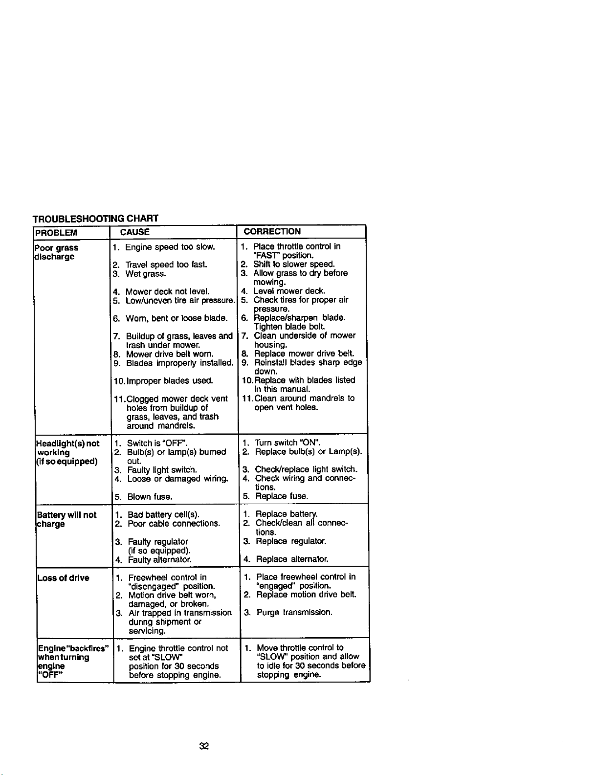
TROUBLESHOOTING CHART
PROBLEM CAUSE
Poor grass 1. Engine speed too slow.
discharge
2. Travel speed too fast.
3. Wet grass.
Headlight(s) not
working
(ifso equipped)
Batterywillnot
charge
-oss of drive
4. Mower deck not level.
5. Low/uneven tire air pressure.
6. Worn, bent or loose blade.
7. BuLIdupof grass, leavesand
trash under mower.
8. Mower drive belt worn.
9. Blades improperly installed.
10.Improper blades used.
11.Clogged mower deck vent
holes from buildup of
grass, leaves, and trash
around mandrels.
1. Switch is"OFF".
2. Bulb(s) or lamp(s) burned
out.
3. Faulty lightswitch.
4. Loose or damaged wiring.
5. Blown fuse.
1. Bad battery cell(s).
2. Poor cable connections.
3. Faulty regulator
(if so equipped).
4. Faulty alternator.
1. Freewheel control in
"disengaged" position.
2. Motion drive belt worn,
damaged, or broken.
3. Air trapped in transmission
during shipment or
servicing.
CORRECTION
1. Place throttlecontrol in
"FAST" position.
2. Shift to slower speed.
3. Allow grass to dry before
mowing.
4. Level mower deck.
5. Check tires for proper air
pressure.
6. Replace/sharpen blade.
Tighten blade bolt.
7. Clean underside of mower
housing.
8. Replace mower drive belt.
9. Reinstall blades sharp edge
down.
10. Replace with blades listed
in this manual.
11.Clean around mandrels to
open vent holes.
1. Turn switch "ON".
2. Replace bulb(s) or Lamp(s).
3. Check/replace light switch.
4. Check widng and connec-
tions.
5. Replace fuse.
1. Replace battery.
2. Check/clean all connec-
tions,
3. Replace regulator.
4. Replace alternator.
1. Place freewheel control in
"engaged" position.
2. Replace motion ddve belt.
3. Purge transmission.
Englne"beckflres" 1. Engine throttlecontrol not 1. Move throttlecontrol to
Nhenturnlng setat "SLOW" "SLOW" position and allow
engine position for 30 seconds to idle for 30 seconds before
"OFF" before stopping engine, stopping engine.
32
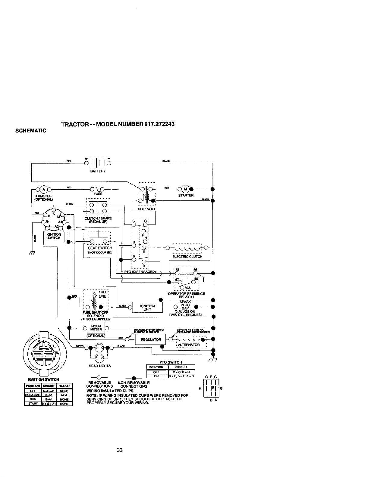
SCHEMATIC
TRACTOR - - MODEL NUMBER 917.272243
BATTERY
AMMETER
(OPTla',U_)
(F SO EQUIPPED)
(OPTI_)
OPERATOR PRESENCE
RELAY #1
_" SPARK
UNiT
J (2 PLUGS ON
TW1NCYL E_GINES)
s_m[Mou_tff _voL11m_ e _ P.m
1p , TER.,TO,;
IGNITION SWITCH
PTO SWITCH
HEAD-LIGHTS pos_lO N CIRCUIT
OFF C÷GrB÷H
ON C÷F_B÷E,A÷O G F C
REMOVABLE NON_:IEMOVABLE _
CONNECTIONS CONNECTIONS H S
WIRING INSULATED CLIPS
NOTS: IF WIRING rNSUkATED CLIPS WERE REMOVED FOR
SERVICING OF UNIT, THEY SHOULD BE REPI_CEO TO D A
PROPERLY SECURE YOUR W_RING,
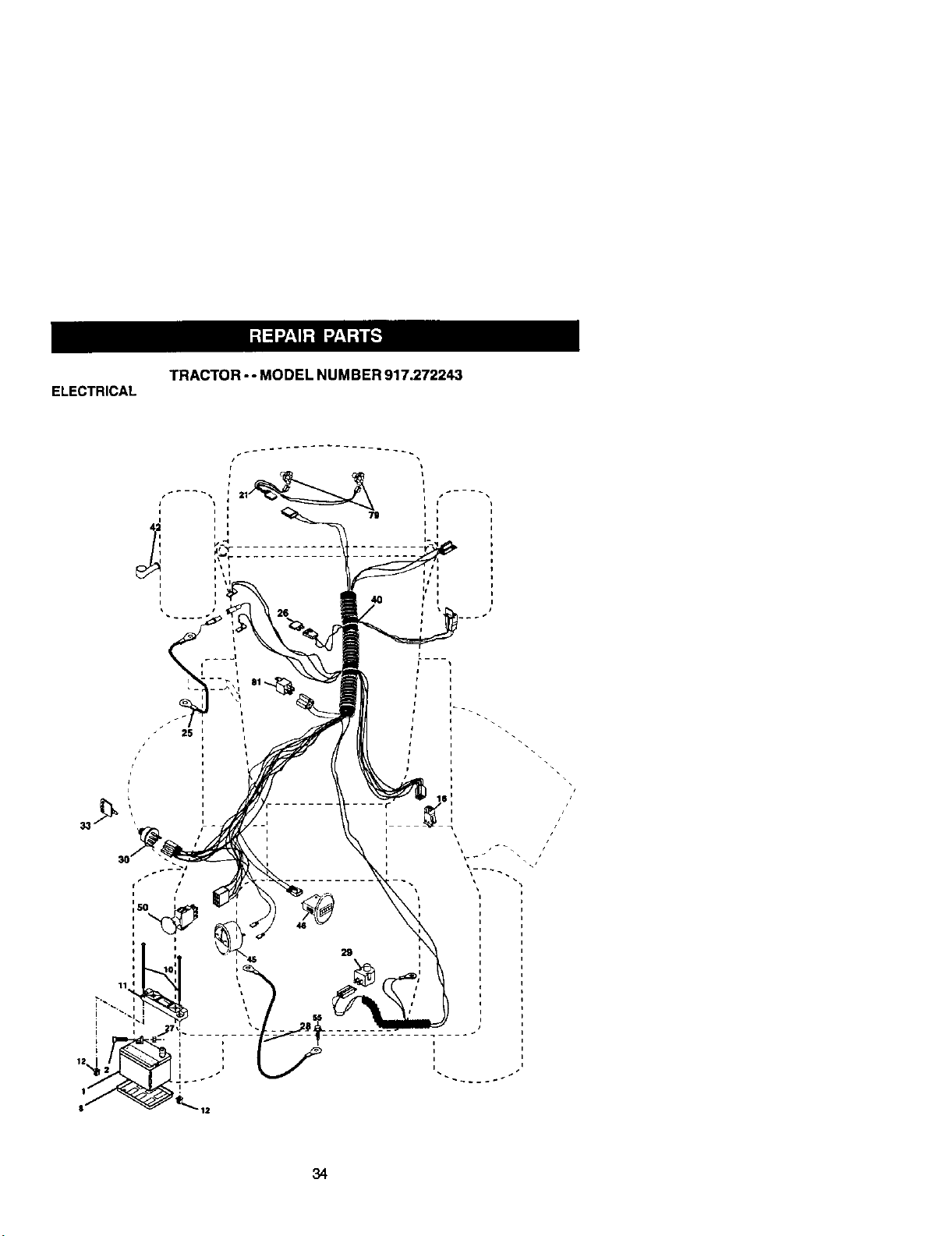
ELECTRICAL
TRACTOR -- MODEL NUMBER 917.272243
i
2s
29

ELECTRICAL
TRACTOR - - MODEL NUMBER 917.272243
KEY PART
NO. NO, DESCRIPTION
1
2
8
10
11
12
16
21
25
26
27
28
29
3O
33
4O
42
45
46
5O
55
79
81
163465 Battery
74760412 BoH, Hex 1/4-20 x 3/4
7603J Tray, Battery
145211 Bolt, Btr Front 1/4-20 x 7-1/2
150109 Holddown Batter/Front Mount
145769 Nut, Push Nylon Battery Front 1/4
153664 Switch Interlock Push-In
175449 Hamess, Light
178_9 Cable, Batter'/
175158 Fuse
73510400 Nut Keps Hex 1/4-20 UNC
145491 Cable,Ground
160784 Switch, Seat
175442 Switch, Ignition
175447 Key
178452 Harness, Ignition
154336 Cover Terminal
177500 Ammeter
177501 Hounneter
178461 Switch Pto
17490508 Screw Thdrol 5/t6-18 x 1/2
175448 Bulb and Holder Asm Haiogen
109748X Reley Asm
NOTE: All component dimensions given in U.S. inches
1 inch = 25.4 mm
35
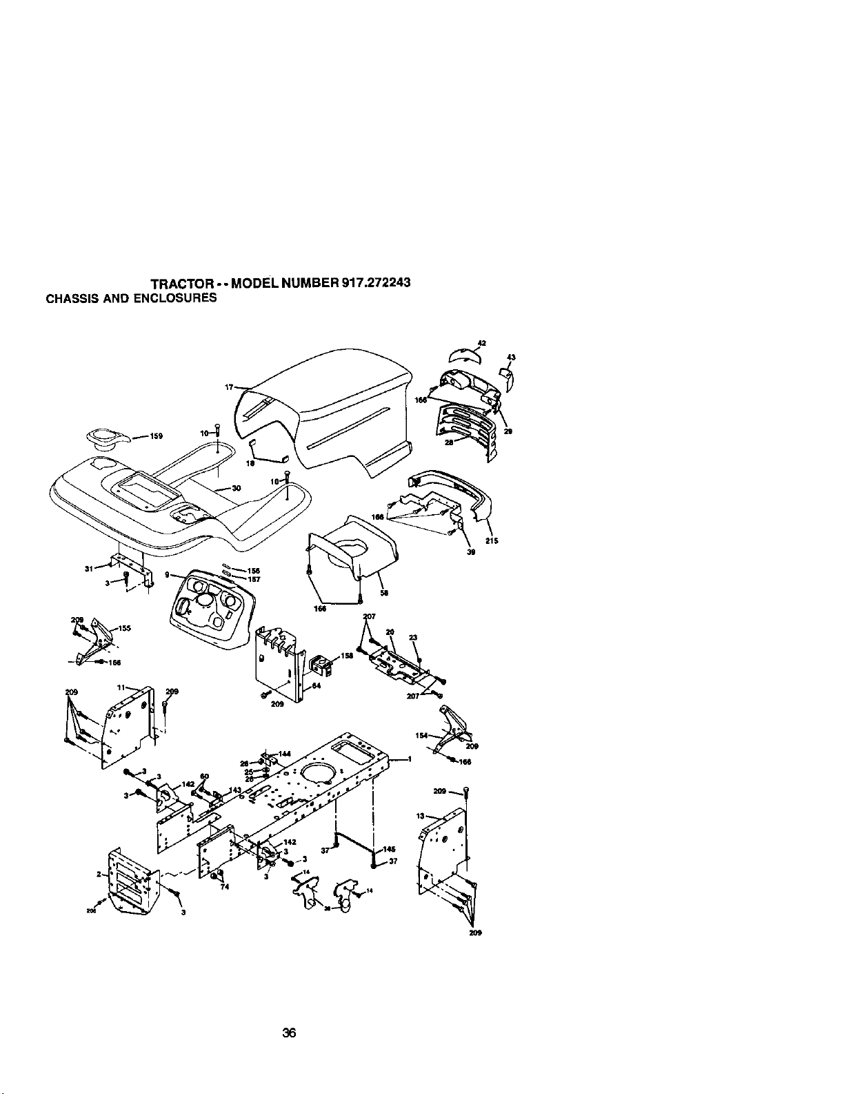
TRACTOR- - MODEL NUMBER 917.272243
CHASSISAND ENCLOSURES
42
29
21S
39
209
36

TRACTOR- - MODEL NUMBER 917.272243
CHASSISAND ENCLOSURES
KEY PART
NO, NO, DESCRIPTION
1
2
3
9
10
11
13
14
17
18
2O
23
25
26
28
29
3O
31
37
38
39
42
43
58
60
64
74
142
143
144
145
154
155
156
157
158
159
166
2O6
2O7
2O9
174619 Chassis
176554 Drawt_,r
1706G612 Screw, 3/8-16 x 3/4
172542X418 Dash
STD53O710 Bolt RDHD SQNK 3/6-16unc x 1
174996 Panel, Dash, LH
179174X010 Panel, Dash, RH
17490608 Screw Thdrol 3/6-16 x 1/2
172540X615 Hood Assembly
126938X BumperHood
156437 Plats Battery
124028X Bushing Snap
19131312 Washer 13/32 x 13/16 x 12 Gauge
STD541437 Locknut, Hex, with Insed _8-16 UNC
174945X418 Gdlle
174944X418 Lightbox Dust
175692X615 Fender,/Fookest
139976 Bracket, Fender/S upport
17490508 Borew, Thdrol. 5/16-18 x 1/2 TYT
175710 Bracket Asm Pivot Mower Rear
174988 Bracket Pivot Hood
174993
STC533707
174997
S]_541437
175702
154966
175582
156524
174679
174680
1638C5
1638O6
162037
172545X599 Lens Lh
172544X599 Lens Rh
Duot Hood
Bolt Rdhd Sqnk 3/8-16 UNC x 3/4
Dash Lower
NutCrownlock 3/8-16 UNC
Plate Reinforcement
Bracket Swaybar Chassis
Bracket Footrest
Rod Pivot Chassis/Hood
Bracket Dash Rh
Bracket Dash Lh
Striker Plats
MagnetYTGT
Parking Bcake Bill
155123X418 Cupholder Stl Btk
164863 HWHDH:-Lo. #13-16x 3/4
170165 Bolt Shoulder 5/16-18
176705(_ Screw Thdrol 5/16-18 x 1/2
172O_612 Borew Hexwsh Thdr 5/8-16 x 3/4
215 172543X615 Bumper
NOTE: All component dimensions given in U.S. inches
1 inch = 25.4 mm
37
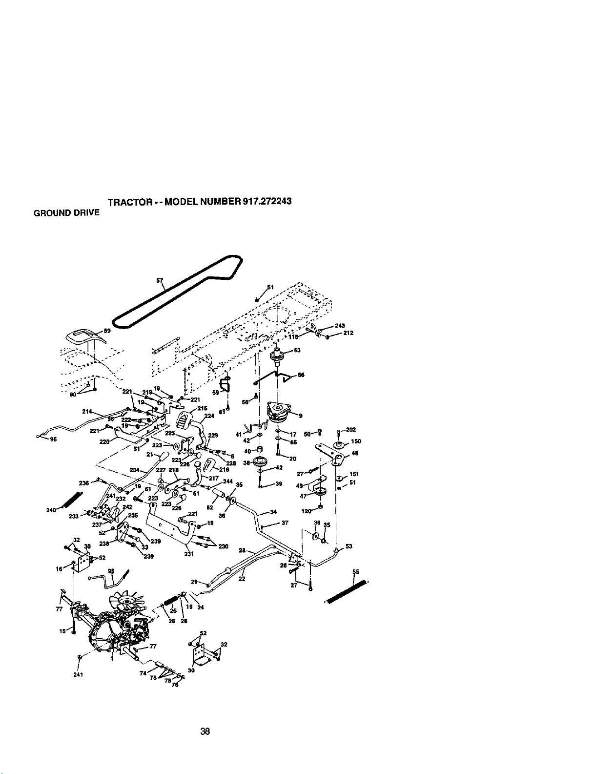
TRACTOR--MODELNUMBER917.272243
GROUNDDRIVE
29
32
241
26 26
74 30
55
° +7
38
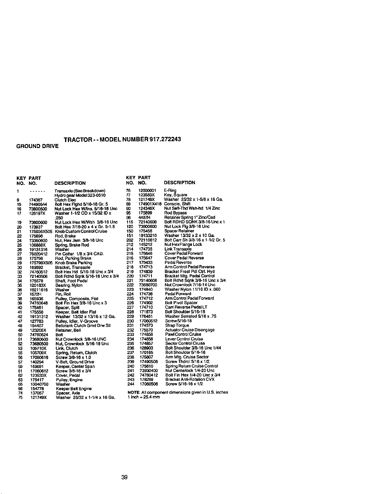
TRACTOR-- MODEL NUMBER 917.272243
GROUND DRIVE
KEY PART KEY PART
NO. NO. DESCRIPTION NO. NO, DESCRIPTION
1 ...... Transaxle (See Breakdown) 76 12000001 E-Ring
Hydro gear Moda1323_)510 77 123583X Key, Square
9 174367 Clutch Elec 78 121748X Washer 23/32 x 1-3/8 x 16 Ga.
15 74490544 Bolt Hex Rghd 3/16-18 Gr. 5 89 174901X418 Console. Shift
16 _ Nut Lock Hex W/ins. 3/16-18 uric 90 124346X Nut Seit-Thd Wsh-hd 1/4 Zinc
17 126197X Washer 1-1/20D x 13/32 ID x 96 175899 Rod Bypass
,250 96 4497H Retainer Spdng 1"Zinc/Ced
19 73800600 NutLockHexW/Wsh 3/6-16Unc 116 721406_6 BoltROHDSQNK3/8-16Uncx1
20 173937 Bolt Hex 7116-20 x 4 x Gr. 5-1.5 120 73900600 Nut Look Rg 3/8-16 Unc
21 1750_6X505 KnobCustomControlCruise 150 175456 SpacerRetainer
22 175896 Rod, Brake 151 1913.3210 Washer 13/32 x 2 x 10 Ga.
24 73350600 Nut, HexJam 3/8=16Unc 2(_ 7211G612 BottCarrSh3/6-16x1-1/2Gr. 5
25 106888X Spdng, Broke Rod 212 145212 Nut HexR_mge Lock
26 19131316 Washer 214 174735 LinkTransaxle
27 76020412 Pincotler 1/Bx3/4CAD. 215 175646 CoverPedalForward
28 175798 ROd, Parking Brake 216 175647 Cover Pedal Reverse
29 175799X5C6 KnobBrakeparldng 217 179433 PedalReverse
30 169592 Bracket, Transaxle 218 174713 Ann Control Pedal Reverse
3_ 74760512 Bolt Hex Hd 3/1 6-18 Unc x 3/4 219 174839 Bracket Frest Pdl Ctd. Hyd
33 721_ Boll Rdhd Sqnk 3/16-18 Unc x 3/4 220 174711 Brackel Mtg. Pedal Control
34 175578 Shaft, Fool Pedal 221 72140606 Bolt Rdhd Sqnk 3/8-16 Unc x 3/4
35 120183X Beadng, Nylon 222 73680700 NUtCrownlock 7/16-14 Unc
36 19211616 Wesher 223 174840 Washer Nylon 11/16 ID x .060
37 1572H Pin, Roll 224 174736 PedalForward
38 165936 Pulley, Composite. Flel 225 174712 Arm Control Pedal Fonvard
39 74760648 Bolt Fin Hex 3/8-16 Unc x 3 226 174902 Bolt Pivot Spacer
40 175461 Spacer, Split 227 174710 Cam Reverse Pedal LT
41 175556 Keeper, Belt Idler Rat 228 171873 Bolt Shoulder 5/16-18
42 19131312 Wesher 13i32x13/16x12Ga. 229 176451 WasherSerrated5/16x.75
47 127783 Pulley, Idler, V-Groove 230 17060512 Screw3/16-18
48 154407 Bellcrank Caltch Gmd Drw Sit 231 174573 Strap Torque
49 1232G6X Retainer, Belt 232 175570 Actuator Cruise Disengage
50 74760624 Bolt 233 174856 Pawl Control Cruise
51 73680600 Nut Crownlock 3/8-16 UNC 234 174858 Levercontrol Cruise
52 73680500 Nut, Cmwnlock 3/16-18 Uric 235 174857 Sector Control CruLse
53 105710X Link, Clutch 236 12890G Boit Shoulder 3/6-16 Unc 1/44
56 105709X Sp_ng, Ret urn, Clutch 237 170165 Bolt Shoulder 3/16-18
56 17060616 Screw 3/6-16 x 1.0 238 175807 Arm Mt9. Cruise Sector
57 140294 V-Belt. GmurKI Drive 239 17490508 Screw Thdrol 5/16 x 1/2
59 169691 Keeper, Conter Span 240 175610 Spdng Retum Cruise Control
61 17060612 Screw 3/8-16 x 3/4 241 73930400 NUtCentedock 1/4o20 Unc
62 123533X Cover, Pedal 242 74780412 Bolt Fin Hex 1/4-20 Unc x 3/4
63 175417 Pulley, Engine 243 178289 Bracket Anti-Rotation CVX
65 10040700 Washe_ 244 170605_t Screw 5/16-18 x 1/2
66 154778 Keeper Belt Engine
74 137057 Spacer, Axle NOTE: All component dimensions given in U.S. inches
75 121749X Washer 23/32x1-114x16Ga. 1 inch = 25.4 mm
39
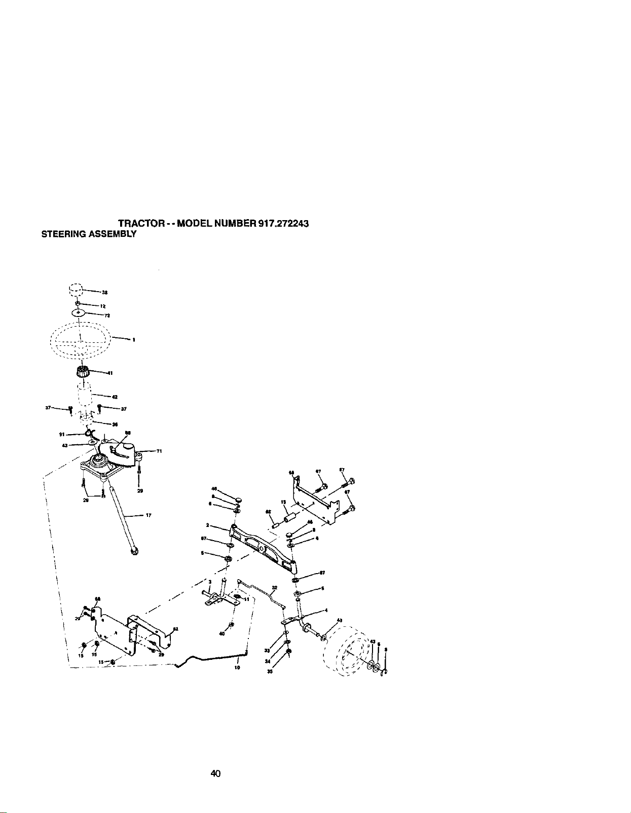
TRACTOR- - MODEL NUMBER 917.272243
STEERINGASSEMBLY
40
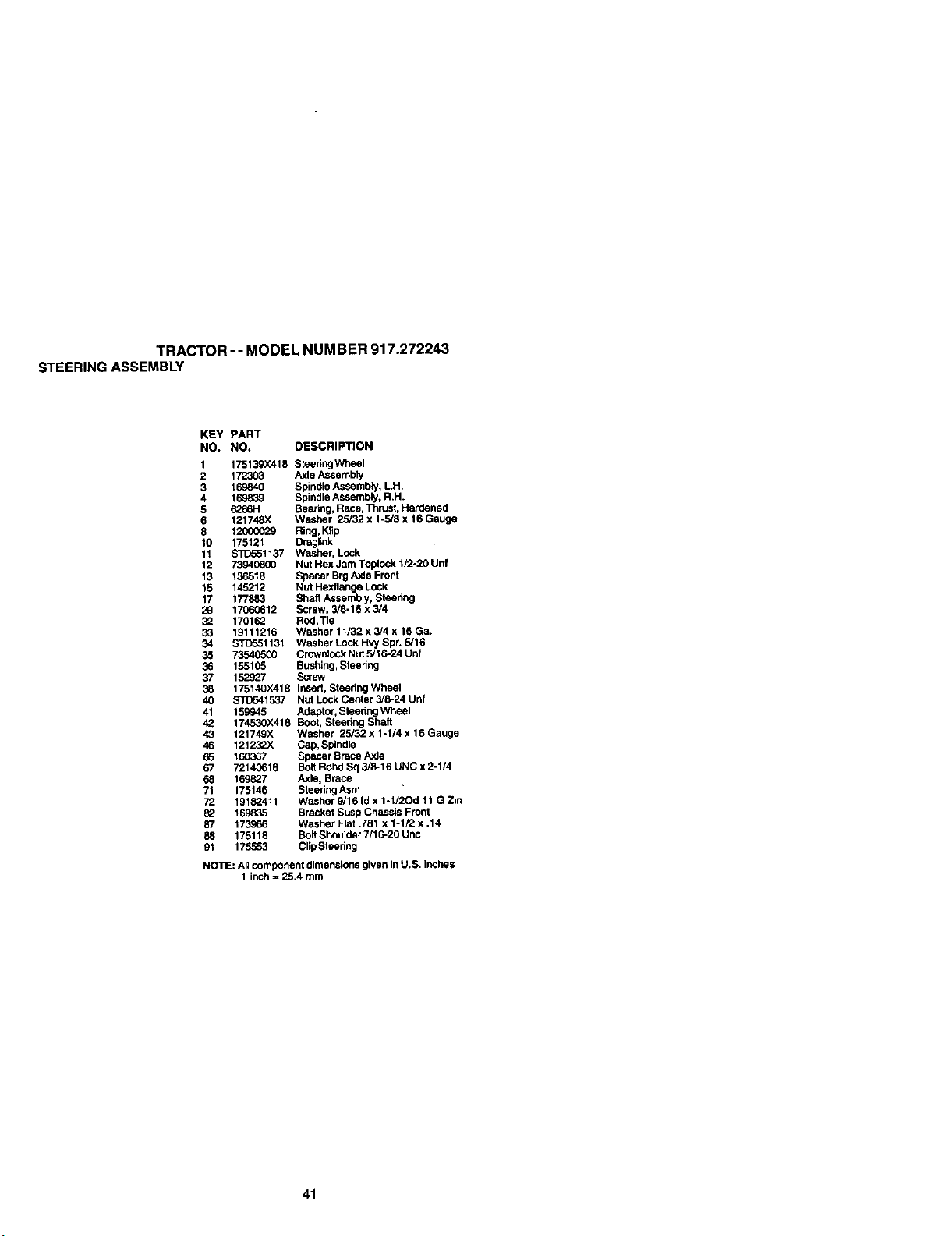
TRACTOR - - MODEL NUMBER 917.272243
STEERINGASSEMBLY
KEY PART
NO. NO. DESCRIPTION
1 175139X418 SteeringWheel
2 172393 Axle Assembly
3 169840 SpindLeAssembly, L.H.
4 169839 Spindle Assembly, R.H.
5 6266H Beating, Race, Thrust, Hardened
6 121748X Washer 25/32 x 1-5/8 x 16 Gauge
8 1_ Ring, Klip
10 175121 Dmgliak
11 STITo51137 Washer, Lock
12 73940_30 Nut Hex Jam Toplock 1/2-20 Unf
13 136518 Spacer Brg Axle Front
15 145212 Nut Hexflange Lock
17 177883 Shaf_Assembly, Steedng
29 17060612 Screw, 3/8-16 x 3/4
32 170162 Rod,Tie
33 19111216 Washer 11/32 x 3/4 x 16 Ga.
34 STD551131 Washer Lock Hv,j Spr. 5/16
35 73540500 Crownlock NUt 5/16-24 Unf
36 155105 Bushing, Steering
87 152_27 Screw
38 17514OX418 Insed. Steering Wheel
40 STD541537 Nut Lock Center 3/8-24 Unf
41 159945 Adaptor. Steering Wheel
42 17453OX418 Boot. Steering Shaft
43 121749X W_sher 25/32 x 1-1/4x 16 Gauge
46 121232X Cap, Spindle
65 160367 Spacer Brace Axle
67 72140615 Bolt Rdhd Sq 3/8-16 UNC x 2-1/4
68 169827 Axle, Brace
71 175146 Steedng ASm
72 1918_411 Washer 9/16 Id x 1-1/2Od 11 G Zin
82 169835 Bracket Susp Chassis Front
87 173966 Washer Flat .781 x 1-1/2 x .14
88 175118 Bolt Shoulder 7/16-20 Unc
91 175553 Clip Steedng
NOTE: Allcomponent dimensions given in U.S. inches
1 inch = 25.4 mm
41
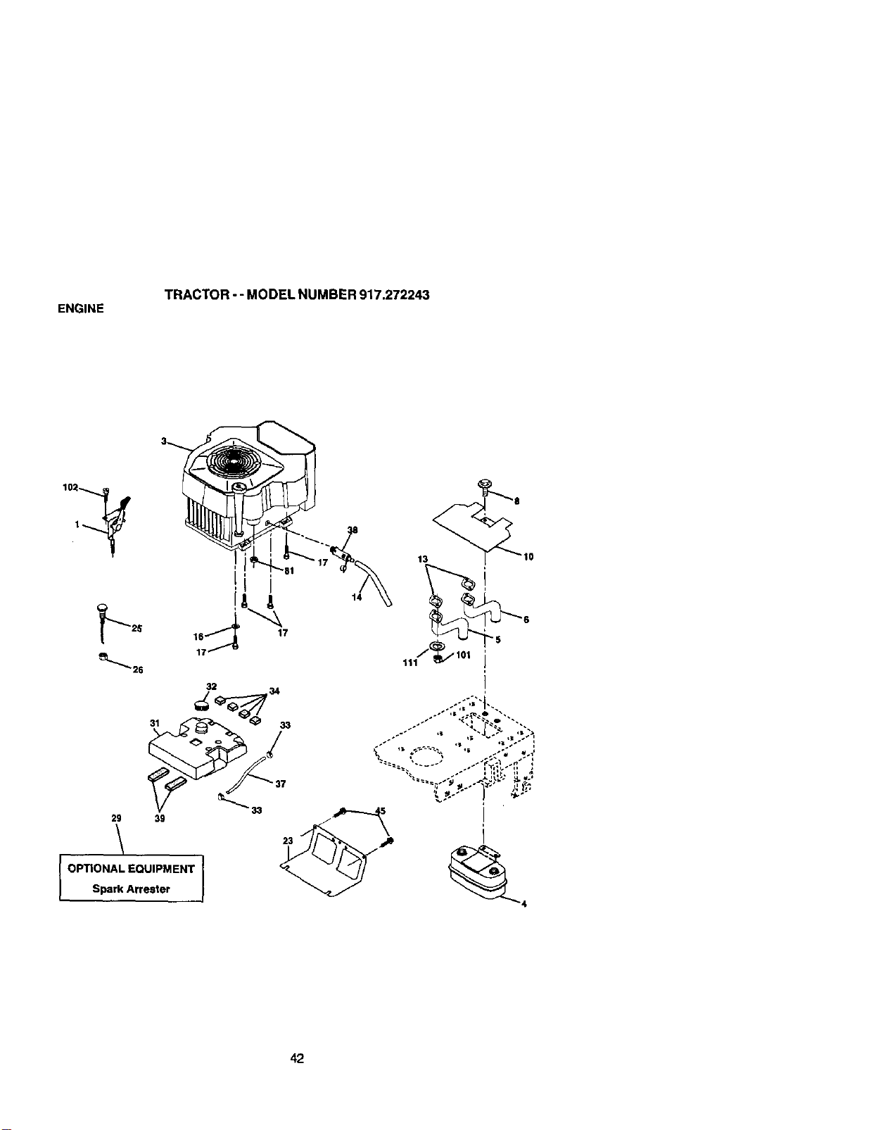
ENGINE
TRACTOR - - MODEL NUMBER 917.272243
32 34
31 33
33
29 39
\
OPTIONAL EQUIPMENT I
Spark Arrester
23
13
14
42

ENGINE
TRACTOR -- MODEL NUMBER 917.272243
KEY PART
NO, NO, DESCRIPTION
1 175439X505 Control, Throgle
3 ....... Engine, (See Breakdown) Kohler Model Number
CV624-65578
4 149723 Muffler
5 146699 Pipe Exhaust Lh
6 146700 Pipe Exhaust Rh
8 171877 Bolt 5/16-18 Unc x 3/4
10 145629 ShksldHeat
13 24-041-02 Gasket KohlerCV18-CV26
(See Engine Breakdown)
14 148456 Tube Drain Oil Easy
16 110506G0 Washer, Lock, External Tooth 3/8
17 17490624 Screw Thdrol 3/8-16 x 1-1/2
23 169837 Shield, Browning/DebdsGuard
25 175441X505 Choke Control
26 7392(ToGO Nut, Keps 3/8-24 UNF
29 137180 Kit, Spark Arrestor
31 157103 TankFuel
32 16i696 CadAsm Fuel
33 123487X Clamp, Hose
34 1(ToO82X Pad, Spacer
37 8543R Line, Fuel
38 148315 Plug Drain Oil Easy
39 109227X Pad, Idler
45 17000612 S_rew Hexwsh Thdr 3/8-16 x 3/4
81 73510400 Nut Keps Hex 1/4-20 UNC
101 M73030800 NutFlangeMS*1.25
1(;2 164863 Screw Hwhd H.-Lo #13015 x 3/4
111 10010500 Washer Split
NOTE: Allcomponent dimensions given in U.S. inches
1 inch = 25.4 mm
43
TRACTOR-- MODEL NUMBER 917.272243
SEATASSEMBLY
KEY PART
NO. NO. DESCRIPTION
1 175134 Seat
2 140551 Bracket, Pivot, Seat
3 7111(_616 Bolt
4 19131610 Washer 13/32 x 1 x 10 Gauge
5 145006 Clip, Push-In Hinged
6 STD541437 Nut
7 124181X Spr;ng, Seat
8 17000616 Screw 3/6-15 x 1-1/2
9 19131614 Washer 13/32 x 1 x 14 Gauge
10 174894 Pan, Seat
11 177957 Knob Seat
12 121246X Bracket, Switch Mounting
13 121248X Bushiug, Snap
KEY PART
NO. NO. DESCRIPTION
14 72050412 Bolt, Carnage 1/4o20 x 1-1/2
15 121249X Spacer, Split
16 123740X Sprig
17 123976X Locknut, Range 1/4 Grade 5
18 124238X Cap Spdng Seat
21 171852 Bolt, Sheutder 5/16-18 UNC
22 STD541431 Nut
24 19171912 Washer 17/32 x 1-3/16 x 12
Gauge
25 127018X Bolt, Shoulder 5/16-18 x .62
NOTE: All component dimensions given in U.S. inches
I inch = 25.4 mm
44
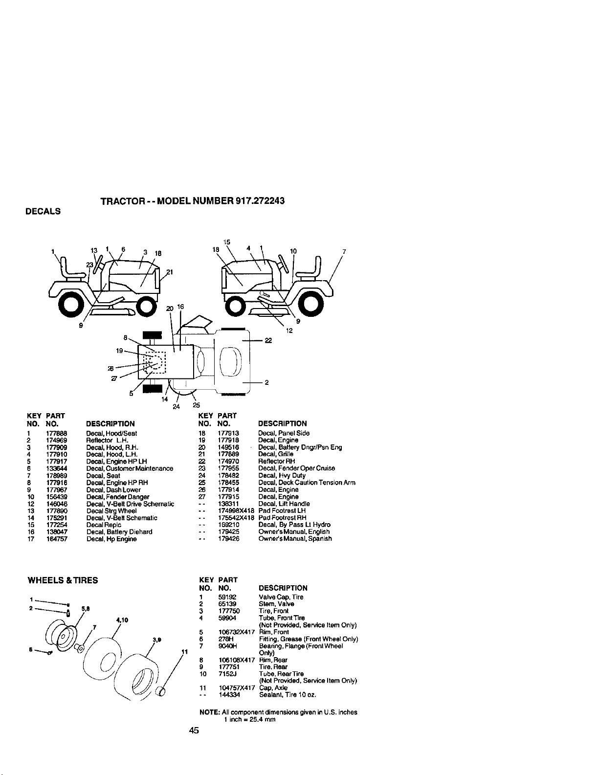
DECALS
TRACTOR - - MODEL NUMBER 917.272243
13
19
15
18
\
10
KEY PART
NO. NO.
2 174969
3 1779O9
4 177910
5 177917
6 133644
7 178989
8 177916
9 177967
10 156439
12 146046
13 177890
14 175291
15 177254
16 138047
17 164757
9
12
KEY PART
DESCRIPTION NO. NO. DESCRIPTION
Decal, HoodJscat 18 177913 Decal, Panel Side
RefleCtor LH. 19 177918 Decal, Engine
Decal, Hood, R.H. 20 149516 Decal, Battery Dngr/Psn Eng
Oecs_tHood, LH. 21 177889 Decal, Gdlle
Deca_,Engine HP LH 22 174970 Reflector RH
Decal, Customer Maintenance 23 177955 Decal, Fender Oper Cruise
Decal, Seat 24 178482 Decal, HW Duty
Decal, Engine HP RH 25 178455 Decal, Deck Cautlen Tension Arm
DecaJ,Dash Lower 26 177914 Decal, Engine
Decal, Fender Danger 27 177915 Decal, Engine
Decal, V-Belt Drive Schematic - - 138311 Decal, L_ Handle
Decal Strg Wheel ** 174998X418 Pad Footrest LH
Decal, V-Belt Schematic * * 175542)(418 Pad Footrest RH
Decal Replc - - 169210 Decal, By Pass Lt Hydro
Decal, Battery Diehard - - 179425 Owner's Manual, English
Decal, Hp Engine - - 179426 Owner's Manual, Spanish
WHEELS &TIRES
2 _ j,8 7
KEY PART
NO. NO. DESCRIPTION
1 591_Z Valve Cap, Tire
2 65139 Stem, Vah/e
3 177750 Tire, Front
4.10 4 59904 Tube, FrontTire
(Not Provided. Service Item Only)
5 10673_.X417 Rim,Front
3,0 6 278H Fitting,Grease (Front Wheel Only)
_/ 7 904G_ Beadng, Flange (Front Wheel
i 11 Only)
8 1G6108X417 Rim, Rear
9 177781 Tire, Rear
10 7152J Tube, Rear Tire
(Not Provided, Service Item Only)
11 104757X417 Cap, Axle
- - 144334 Sealant, Tire 10 oz.
NOTE: All component dimensions given in U.S. inches
1 inch = 25.4 mm
45
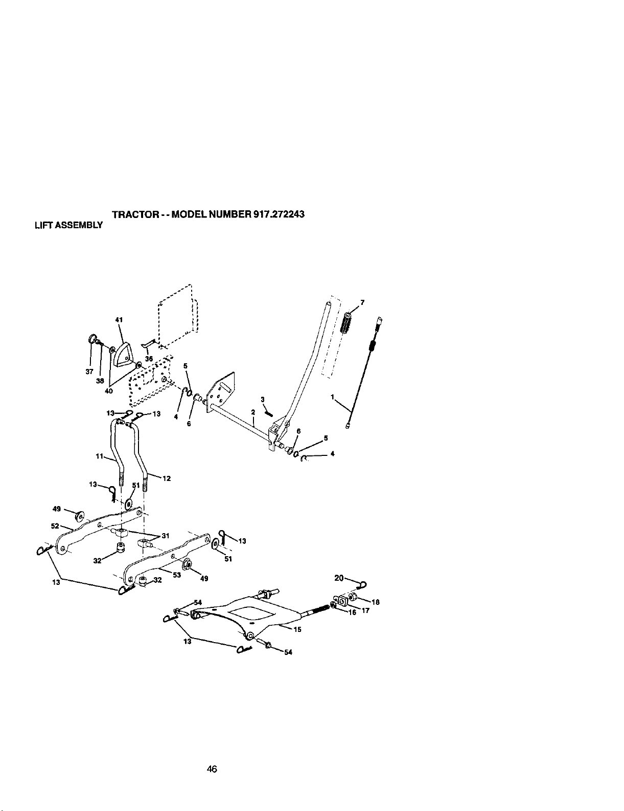
TRACTOR- - MODEL NUMBER 917.272243
LIFTASSEMBLY
37
38
4O
13
3
6
46
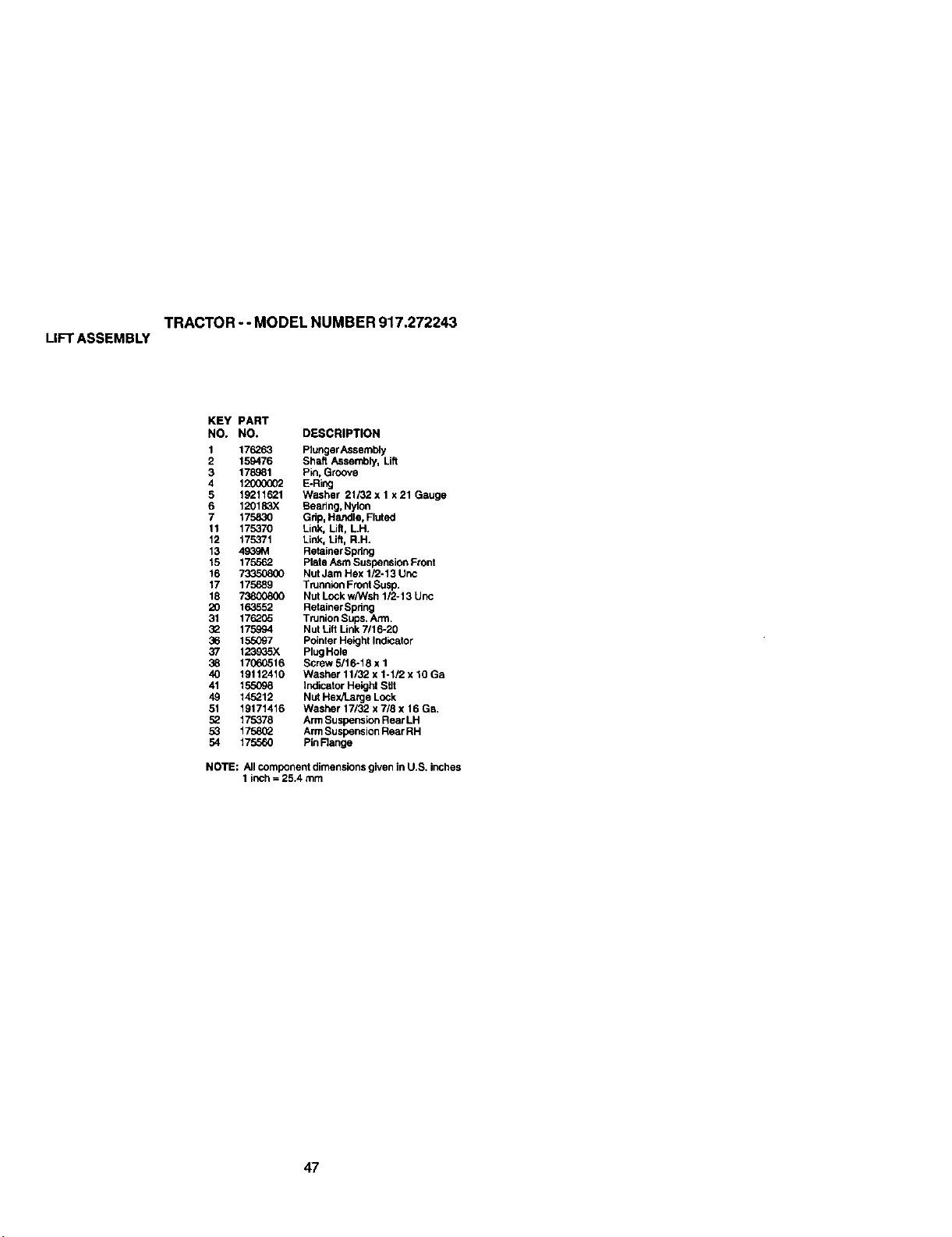
TRACTOR-- MODEL NUMBER 917.272243
LIFTASSEMBLY
KEY PART
NO, NO. DESCRIPTION
1 176263 Plunger Assembly
2 159476 Shaft Assembly, Lift
3 178..°81 Pin, Groove
4 12500002 E-Ring
5 19211621 Washer 2t/32 x 1 x21 Gauge
6 120183X Beadng, Nyion
7 175830 Gdp, Handle, Fluted
11 175370 Link, Lift, L.H.
12 175371 Link, Lift, R.H.
13 4939M Retainer Spdng
15 175562 Plate Asm Suspension Front
16 73350800 Nut Jam Hex 1/2-13 Unc
17 175689 TrunnLonFront Susp.
18 _ Nut Lockw/Wsh 1/2-13 Unc
20 163552 Retainer Spdng
31 176205 Trunion Sups. Arm.
32 175994 Nut Lift Link 7/16-20
36 155097 Pointer Height Indicator
37 123935X Plug Hole
38 17660516 Screw 5/16-18 x 1
40 19112410 Washer 11/32 x 1-1/2 x 10 Ga
41 155098 Indicator Height Stlt
49 145212 Nut Hex/Latge Lock
51 19171416 Washer 17/32 x 7/8 x 16 Ga.
52 175378 Arm Susponsion Rear LH
53 175802 Arm Suspension Rear RH
54 175560 Pin Range
NOTE: All component dimensions given in U.S. inches
1 inch= 25.4 mm
47
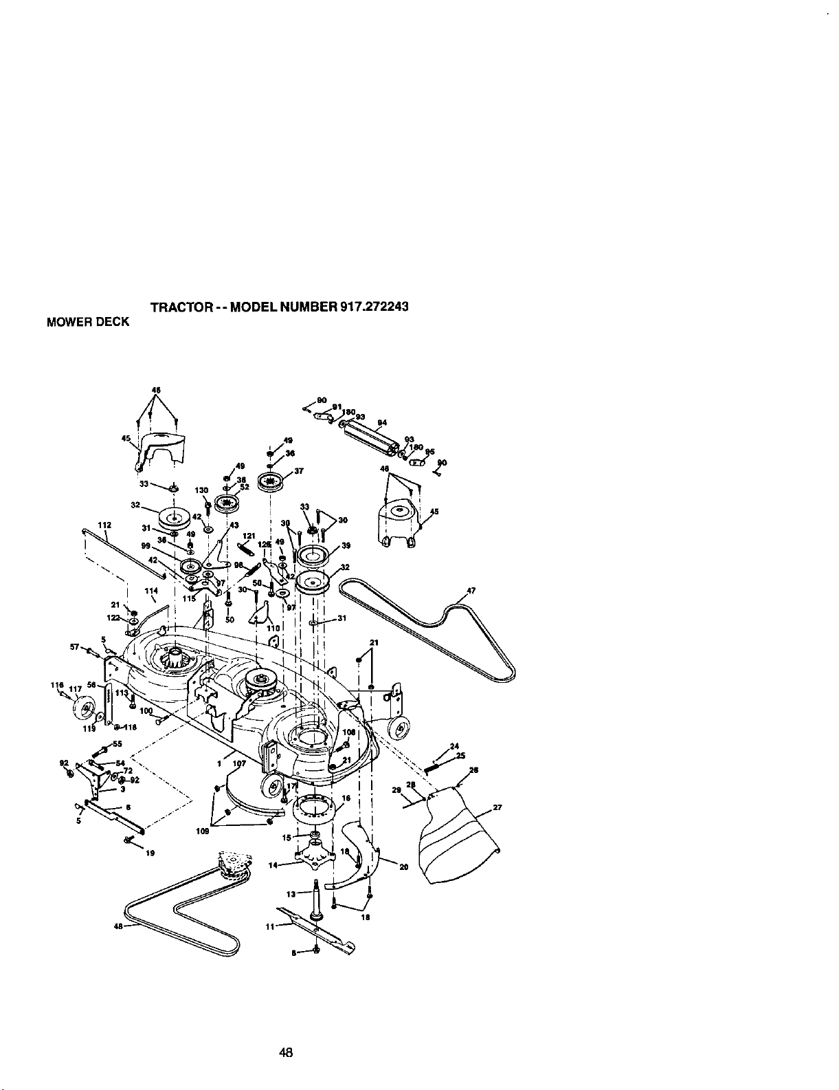
TRACTOR-- MODEL NUMBER 917.272243
MOWERDECK
112
i
21 '
130
116
109
19
18
48
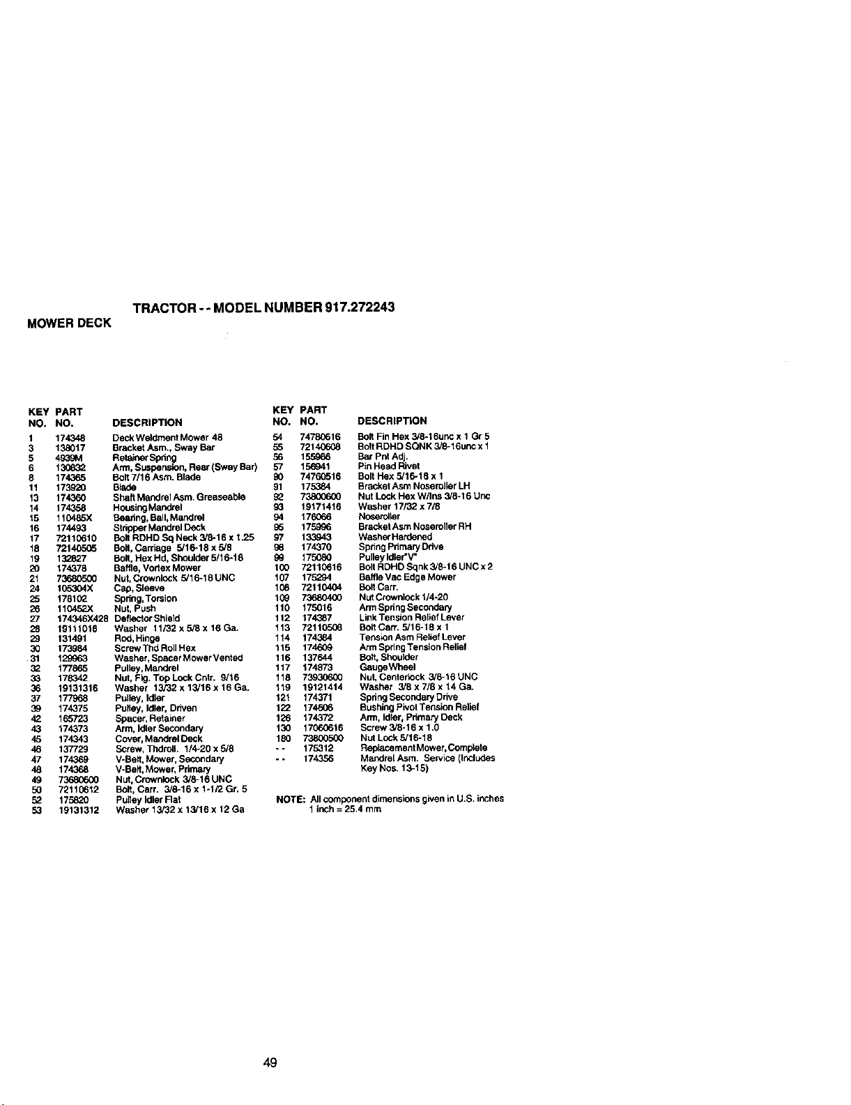
TRACTOR-- MODEL NUMBER 917.272243
MOWERDECK
KEY PART KEY PART
NO. NO. DESCRIPTION NO. NO.
I 174348 Deck Weldment Mower 48 54 7478C616
3 138017 Bracket Asm., Sway Bar 55 72140608
5 46_9M Retainer Spring 56 155986
6 130832 Arm, Suspension, Rear (Sway Bar) 57 156941
8 174365 Bolt 7/16 Asm. Blade 90 74760516
11 173920 Bh_de 91 175384
13 174360 Shaft Mandrel Asm. Greaseaple 93 738006(30
14 174358 Housing Mandrel 93 19171416
15 110485X Baadng, Ball, Mandrel 94 176066
16 174493 Stripper Mandrel Deck 95 175996
17 72110610 Bolt RDHD Sq Neck 3/8-16 x 1.25 97 133943
18 72140505 Bolt, Carriage 5/16-18 x 5,'8 98 174370
19 132827 Bolt, Hex Hd, Sheulder 5/16-18 93 175080
20 174378 Baffle, Vodex Mower lCO 72110616
21 73680500 Nut, Crownlock 5/16-18UNC 107 175294
24 105304X Cap, Sleeve 108 72110404
25 178193 Spdng,Torsion 109 736804G0
26 110452X Nut, Push 110 175016
27 174346X428 DeflectorShield 112 174387
28 19111016 Washer 11/32xsi8x16Ga. 113 72110506
29 131491 Rod, Hinge 114 174384
30 173984 Screw Thd Roll Hex 115 174609
31 129963 Washer, Spacer Mower Vent ed 116 137644
32 177865 Pulley,Mandrel 117 174873
33 178342 Nut, FIg. TopLockCntr. 9/'16 118 73930600
36 19131316 Washer 13/32 x 13/16 x 16 Ga. 119 19121414
37 177968 Pulley, Idler 121 174371
39 174375 Pulley, Idler, Driven 122 174606
42 165723 Spacer, Retainer 126 174372
43 174373 Arm, IdiorSecondary 130 17060616
45 174343 Cover, Mandrel Deck 180 7380(T_0
46 137729 Screw, ThdrolL 1/4-20 x 5/8 -- 175312
47 174369 V-Belt, Mower, Secondary -- 174356
48 174368 V-Belt, Mower, Pdrnmy
49 73680600 Nut, Crownlock 3/6-16 UNC
50 72110612 Bolt, Carr. 3/6-16 x I-1F2 Gr. 5
93 175820 Pulley Idler Rat
53 19131312 Washer 13/32 x 13/16 x 12 Ga
DESCRIPTION
Bolt Fin Hex 3/8-16unc x 1 Gr5
Bolt RDHD SQNK 3/8-16unc x 1
Bar Pnt Adj.
Pin Head Rivet
Bolt Hex 5/16-18 x 1
Bracket Asm Nosemller LH
Nut Lock Hex W/Ins 3/6-16 Unc
Washer 17/32 x 7/.8
Nosetolter
Bracket Asm Noseroller RH
Washer Hardened
Spring Pdmary Ddve
Pulley Idler"V"
Bolt RDHD Sqnk 3/8-16 UNC x 2
Baffle Vac Edge Mower
Bolt Carr.
Nut Crownlock 1/4-20
Arm Spring Secondary
LinkTension Relief Lever
Bolt Can'. 5/16-19 x 1
Tension Asm Relief Lever
Arm Spring Tension Relief
Bait, Shoulder
GaugeWheel
Nut, Centeriock 3/6-16 UNC
Washer 3/8 x 7/9 x 14 Ga.
Spring SecondaryDrive
Bushing Pivot Tension Relief
Arm, Idler, Primary Deck
Screw 3/8-16 x 1.g
Nut Lock 5/16-18
Raplacement Mower, Complete
MandrelAsm. Service (Includes
Key Nos. 13-15)
NOTE: All component dimensions given in U.S. inches
1 inch = 25,4 mm
49
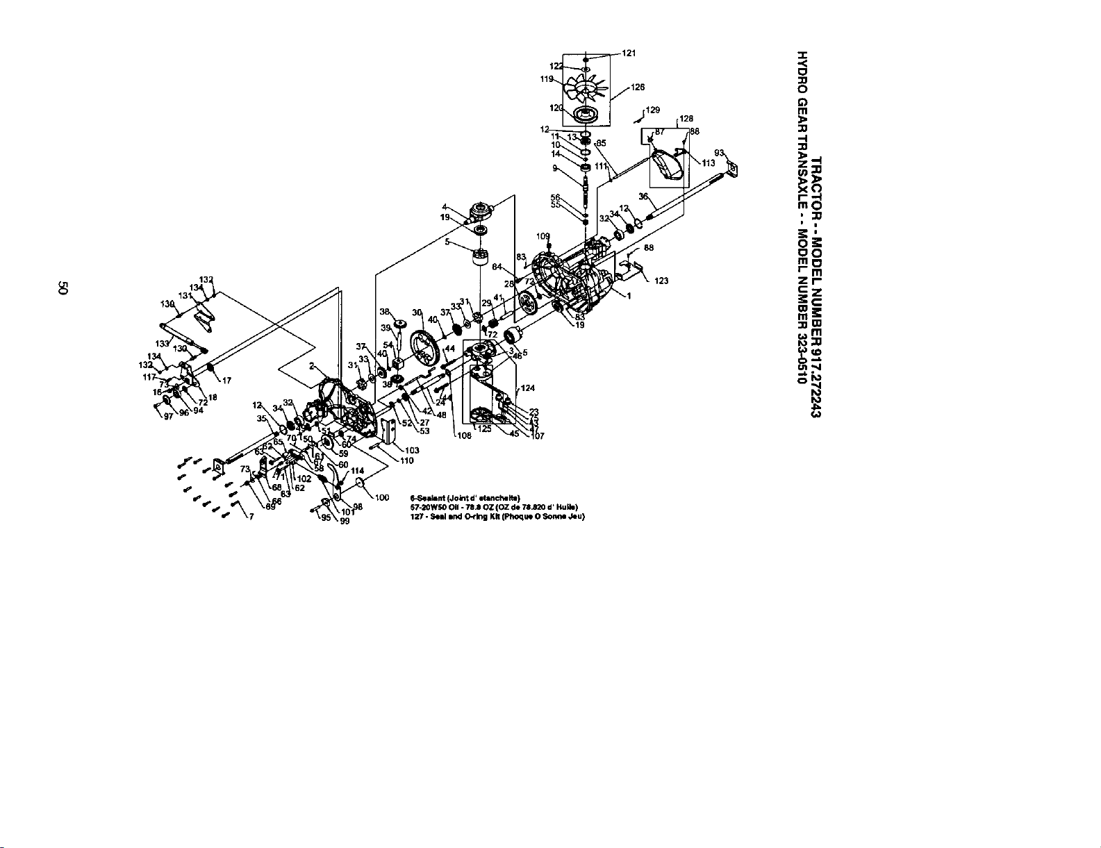
12;
12(
124
_19
,Aj129 128
88
x_
, :;0
I i
oO
r- m
zr-
::0_
_m
ll_ealant (Joint d' etancheite)
b'7.2OWSOOil. 78JJ OZ (OZ de 78.820 d, HuLIe)
127 - Seal rand O-ring Kit (Phoque 0 Somle Jeu)
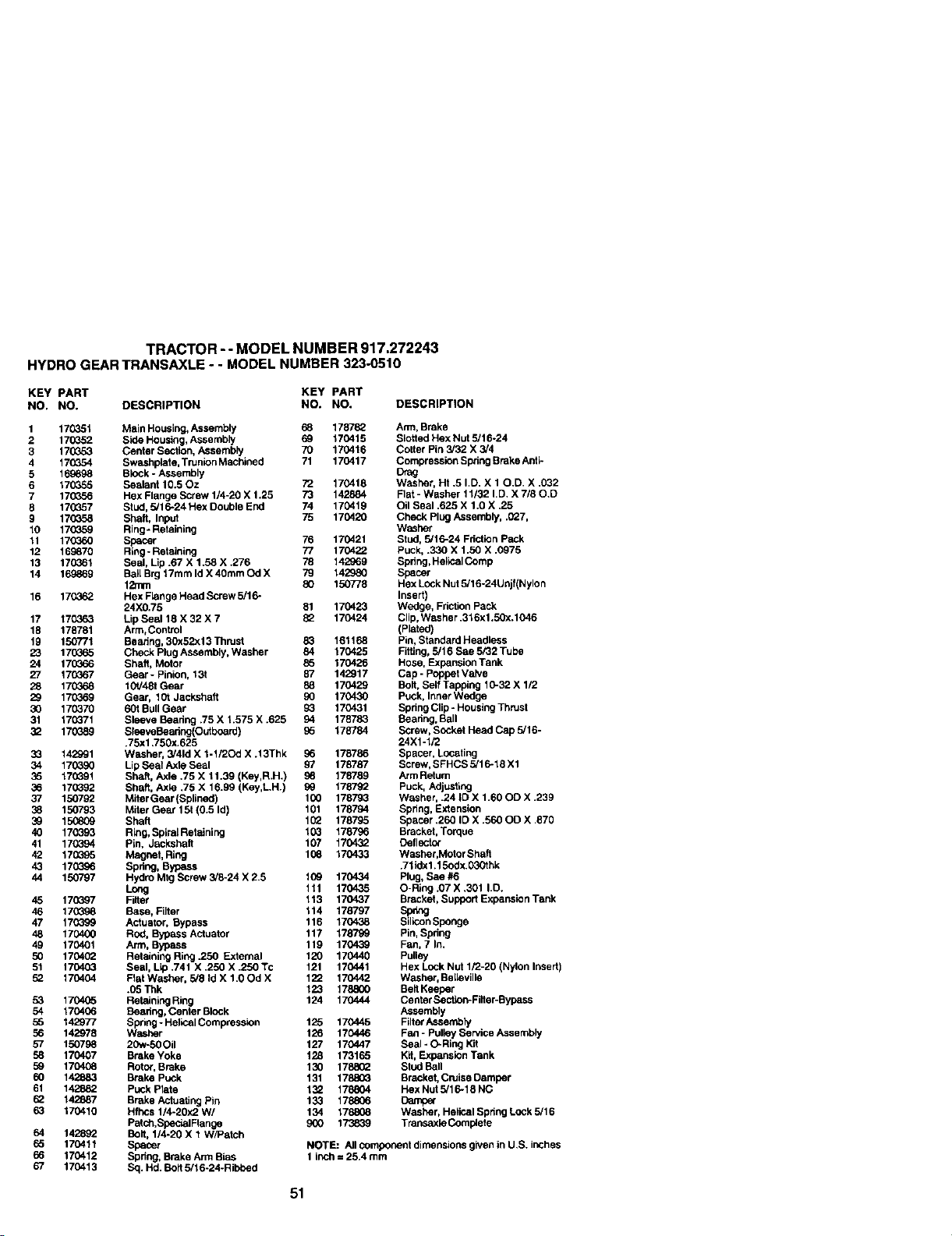
TRACTOR -- MODEL NUMBER 917.272243
HYDROGEARTRANSAXLE- - MODELNUMBER323-0510
KEY PART KEY PART
NO, NO, DESCRIPTION NO. NO. DESCRIPTION
1 170351 Main Housing, Assembly 68 178782 Arm, Brake
2 170_52 Side Housing, Assembly 69 170415 Slotted Hex Nut 5/16-24
3 17G553 Center Section, Assembly 70 170416 Cotter Pin 3/32 X 3/4
4 17G35.4 Swashplate, Trunlen Machined 71 170417 Compression Spring Brake Anti-
5 169898 Block - Assembly Drag
6 170355 Sealant 10.50z 72 170418 Washer, Ht .5 I,D. X 10.D, X .032
7 17(_,56 Hex Flange Screw 1/4-20 X 1.25 73 142884 Flat - Washer 11/32 I.D. X 7/80.D
8 170357 Stud, 5/16-24 Hex Double End 74 170419 Oil Seal .625 X 1.0 X .25
9 17G358 Shaft, Input 75 170420 Check Plug Assembly, .(}27,
10 17CG59 Ring-Retaining Washer
11 170360 Spacer 76 170421 Stud, 5/16-24 Fdction Pack
12 169870 Ring- Retaining 77 170422 Puck, .330 X 1.50 X .0975
13 170361 Seal, Lip .67 X 1.58 X .276 78 142969 Spdng, Haiioai Comp
14 169869 Ball Brg 17mm Id X40mm Od X 79 142980 Spacer
12ram 80 150778 Hex Lock Nut 5/16-24Unjf(Nylon
16 17(J_62 Hex Flenge Head Screw 5/16- Insert)
24X0.75 81 170423 Wedge, Fdction Pack
17 170363 Lip Seal 18 X 32 X 7 82 170424 Clip, Washer .316x1.50x.1046
18 178781 Arm,Control (Plated)
19 150771 Bearleg, 30x52xl 3 Thrust 83 161168 Pin, Standard Heedless
23 170365 Check Plug Assembly, Washer 84 170425 Fitting, 5/16 Sae 5/32 Tube
24 170066 Shaft, Motor 86 170426 Hose, Expansion Tank
27 17(_367 Gear - Pinion, 13t 87 142917 Cap - Poppet Valve
28 1703_8 10t/48t Gear 88 170429 Bolt, Self Tapping 10-32 X 1/2
29 17g_69 Gear, 10t Jacksheft 90 170430 Puck, InnerWedge
30 170370 60t Bull Gear 9_ 170431 Spdng Clip - HousingThrust
31 17033'1 Sleeve Bearing .75 X 1.575 X .625 94 178783 Bearing, Ball
32 1_9 SleeveBeadng(Out board) 95 178784 Screw, Socket Head Cap 5/16-
.75xl .750x.625 24X1-1/2
3:3 142991 Washer, 3/41d X 1-1/2Od X .13Thk 96 178786 Spacer, Locating
34 170390 Lip Seal Asle Seal 97 178787 Screw, SFHCS 5/16-18 X1
35 17_91 Sha5, Axle .75 X 11.39 (Key,R.H.) 98 178789 Arm Return
36 170392 Shaft, Axle .75 X 16.99 (Key,L.H.) 99 178792 Puck, Adjusting
37 150792 MaerGear(Splined) 1(]0 178793 Washer, .24 ID X 1.60 OD X .239
38 150793 Miter Gear 15t (0.5 Id) 101 178794 Spring, Extension
39 15(J809 Shaft 1(_ 178795 Spacer .260 ID X .560 OD X ,870
40 170393 Ring, Spiral Retaining 103 178796 Bracket, Ton:lue
41 170394 Pin. Jackshaft 107 170432 Deflecio_
42 17_95 Magnet, Ring 108 170433 Washet,Moior Shaft
43 170396 Spdng, Bypass .71idx1.15odx.030thk
44 150797 Hydro Mtg Screw 3/8-24 X 2.5 1(_9 170434 Plug, Sae #6
Long 111 170435 O-Riog .07 X .301 I.D.
45 17Q_97 Filter 113 170437 Bracket, Support Expenaion Tank
46 17(]_98 Base, Filter 114 178797 Sp_g
47 17(_99 Actuator. Bypass 116 170438 SiliconSpenge
48 170400 Red, Bypass Actuator 117 178799 Pin, Spring
49 170401 Arm, Bypass 119 170439 Fan, 7 In.
50 170402 Retaining Ring .250 External 120 170440 Pulley
51 170403 Seal, Lip .741 X .250 X .250 Tc 121 170441 Hex Lock Nut 1/2-20 (Nylon Insert)
52 170404 Fiat Washer, 5/8 Id X 1.OOd X 122 170442 W_sher, Belleville
.05 Thk 123 178800 Belt Keeper
53 1704_5 Relaining Ring 124 170444 Cenler Section-Flit er-Bypass
54 170406 Beadng, Center Block Assembly
55 142977 Spdng- Haiical Comwession 125 170445 FilterAssembly
56 142978 Washer 126 170446 Fen - Pulley Service Assembly
57 150798 20w-50 Oil 127 170447 Seal -C_Ring Kit
58 170407 Brake Yoke 128 173165 Kit, Expansion Tank
59 170406 Rotc,r.Brake 130 1788(_ Stud Ball
60 142883 Brake Puck 131 178803 Bracket, Cruise Damper
61 142882 Pu_..kPlate 132 178_04 Hex Nu15/16-18 NC
62 142887 Brake Actuating Pin 133 178806 Damper
63 170410 Hfhcs 1/4-20x2 W/ 134 178808 Washer, Haiical Spdng Lock 5/16
Patch,Spac_lRange 900 173839 Transaxle Complete
64 142892 Bolt, 1/4-20 X 1 W/Patch
66 170411 Spacer NOTE: All component dimensions given in U,S. inches
66 170412 Spring, Brake Arm Bias 1 inch = 25.4 mm
67 170413 Sq. Hd. Bolt 5/16-24-Ribbed
51
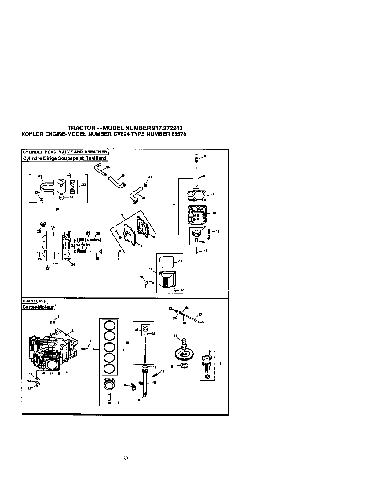
TRACTOR- - MODEL NUMBER 917.272243
KOHLERENGINE-MODELNUMBERCV624TYPE NUMBER65578
C_tItInNdDrEeRDHirEi_D'SOIuL_:peNetRRenE_f/HrEdRI
\ lU
I a
i
/I
.j.I
O--11
O/ fp_,.
_ '-_,_j-'
52
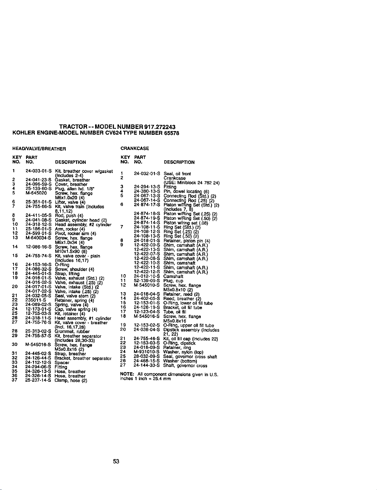
TRACTOR -- MODEL NUMB ER 917.272243
KOHLER ENGINE-MODEL NUMBER CV624 TYPE NUMBER 65578
HEAD/VALVE/BREATHER CRANKCASE
KEY PART KEY PART
NO. NO. DESCRIPTION NO. NO, DESCRIPTION
1 24-O33-01-S Kit, breather COverw/gasket
(includes 2-4)
2 24-041-23-S Gasket, breattier
3 24-096-59-S Cover, breather
4 25-139-60-S Plug, allen hd. 1/8"
5 M-645020 Screw, hex. flange
M6xl.0x20 (4)
6 25-351-01-S Utter valve (4
7 24-755-66-S Kit, vave tram ncudes
8,11,12)
8 24-411-05-S ROd,push (4)
9 24-041-08-S Gasket, cylinderhead (2)
10 24-318-12-S Head assembly,#2 cylinder
"=1 25-_86-01 -S Arm,rocker (4)
12 24-599-01 -S Pivot, rockerarm (4)
13 M-640034-S Screw, hex. flange
M6x1.0x34 4)
14 12-086-16-S Screw, hex. lange
M10xl.Sxg0 (6)
15 24-755-74-S Kit,valve cover- plain
(Includes 15,17)
16 24-153-1g-S O-Ring
17 24-086-32-S Screw,shoulder(4)
18 24-445-01-S Strap, lifting
19 24-016-01-S Valve, exhaust (Std.) (2)
24-016-02-S Valve, exhaust (.25) (2)
20 24-017-01-S Valve, intake (Std.) (2
24-017-02-S Valve, intake (.25) (2)
21 24-032-05-S Seal, valve stem (2)
22 235011-S Retainer, spdng (4)
23 24-O89-02-S Spring, valve (4)
24 12-173-01-S Cap, valve spring(4)
25 12-755-03-S Kit, retainer (4)
26 24-318-11-S Head assembly,#1 cylinder
27 24-755-76-S Kit,valve cover- breather
(incl. 16,17,26)
28 25-313-02-S Grommet. rubber
29 24-755-57-S Kit, breather separator
(Includes 28,30-33)
30 M-545016-S Screw, bex. flange
M5x0.Sx16 (2)
31 24-445-02-S Strap, breather
32 24-126-44-S Bracket, breather separator
33 24-112-12-S Spacer
34 24-294-06-S Fitting
35 24-326-13-S Hose. breather
36 24-326-14-S Hose, breather
37 25-237-14-S C4_mp,hose (2)
24-032-01 -S
24-294-13-S
24-38G-13-S
24-067-13-S
24-067-14-S
24-874-17-S
Seat, oil front
Crankcase
(USE: Miniblock24 782 24)
Fittin
Pin, _owet tocagn
Conne_in
7
8
9
10
11
12
24-874-18-S
24-874-19-S
24-874-14-S
24-108-11-S
24-108-12-S
24-108-13-S
24-018-01-S
12-422-09-S
12.422-13-S
12-422-07-S
12.422-08-S
12-422-10-S
12-422-11 -S
12-422-12-S
24-012-10-S
52-139-09-S
M-545010-S
13 24-018-04-S
14 24-402-05-S
15 12-153-01-S
16 24-126-19-S
17 12-123-04-S
18 M-545016-S
lg 12o153-02-S
20 24-038-04-S
21 24°755-46-S
22 12-153-03-S
23 24-018-09-S
24 M-931010-S
25 28-032-09-S
26 24-468-15-S
27 24-144-33-S
Ring Set
Shim, c_
Shim, camshaft I
Shim, camshaft
Shim, camshaft,
Shim, camshaft
Sh_m, camshaft A.R.
Shim, camshatt tA.R. /
Camshaft
Plug, cup
Screw, hex. flange
MSx0.Sxl0 (2)
Retainer, reed (2)
Reed, breather (2)
O-Ring, lower oil tiff tube
Bracket, oil fi)) tube
Tube, oil fill
Screw, hex. flange
M5x0.8x16
O-Ring, uppeT oll fiI_tube
Dipstick assembly (includes
21 22)
Kit, oil fill cap (Ir',cludes 22)
O-Ping, dipstick
Retainer, ring
Washer, nylon (top)
Seal governor cross shaft
Washer (bottom
Shaft, governor cross
NOTE: All component dimensions given in U.S.
inches 1 inch = 25.4 mm
53
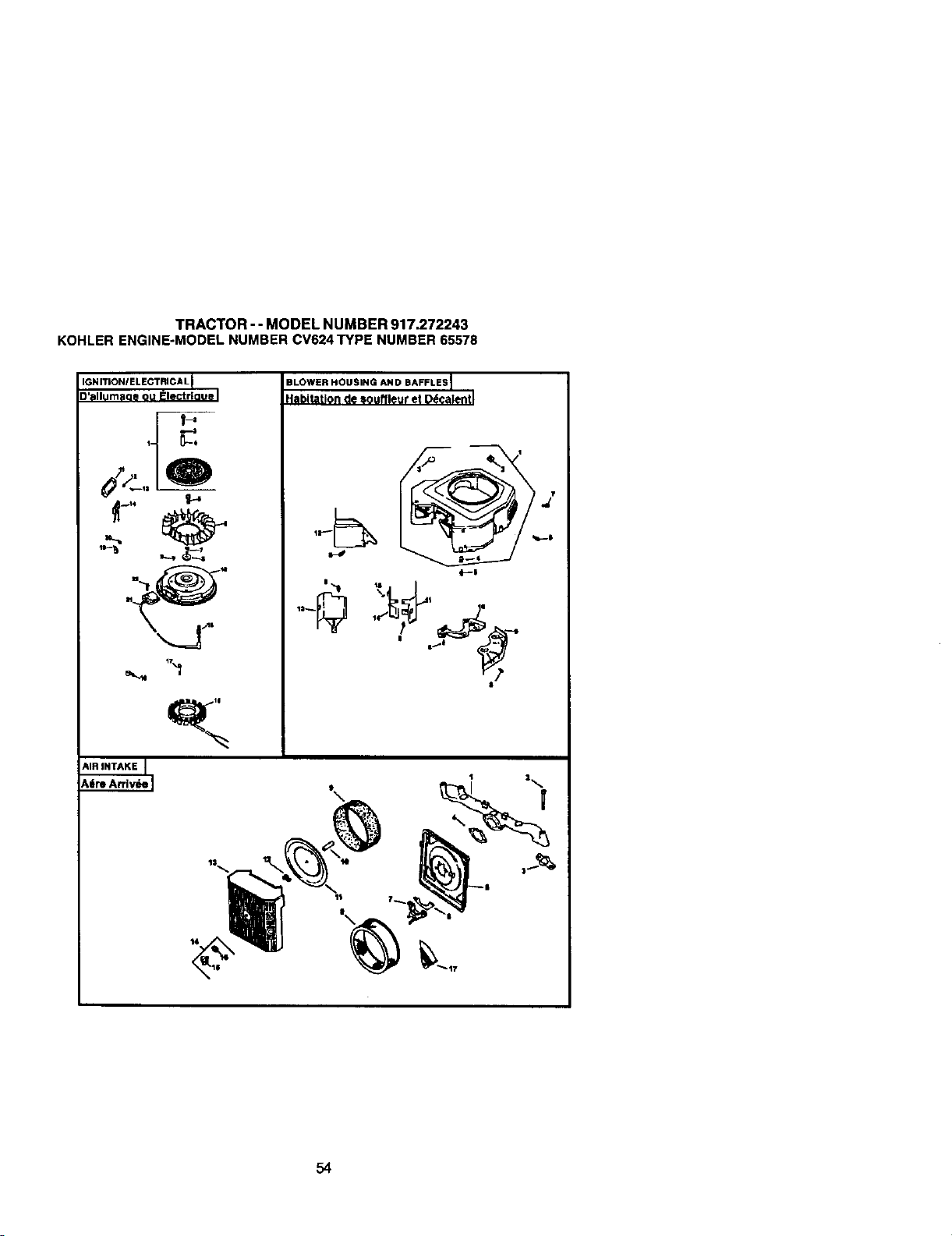
TRACTOR - - MODEL NUMBER 917,272243
KOHLERENGINE-MODELNUMBERCV624TYPENUMBER65578
IGNITIONIELECTRICA L
[_'allumaoe ou IFlectrl(]ue
BLOWER HOUSING AND BAFFLES I
_labitation de souffleur el Ddcalentl
t4
54
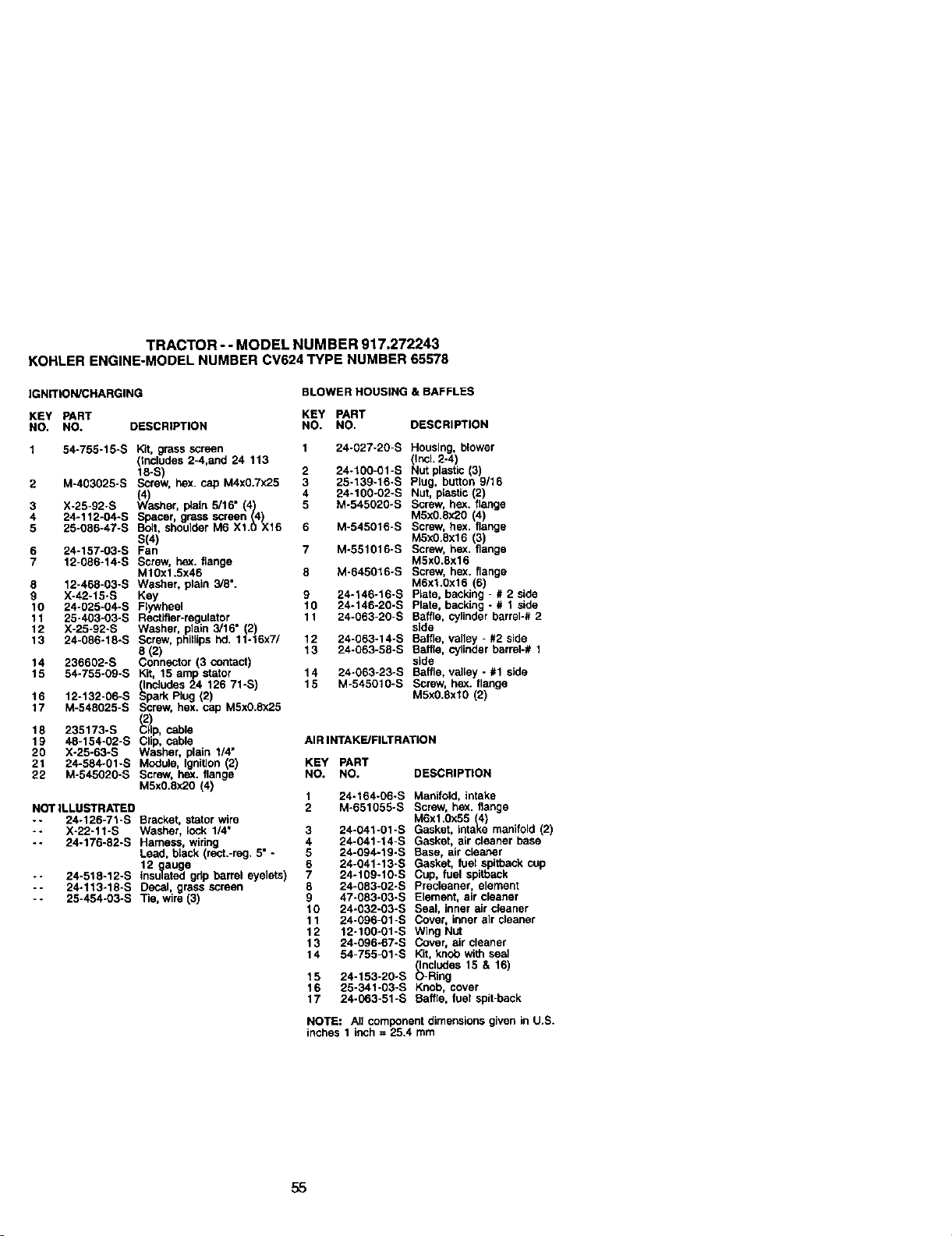
TRACTOR-- MODEL NUMBER 917.272243
KOHLERENGINE-MODELNUMBERCV624TYPE NUMBER65578
IGNITION/CHARGING
BLOWER HOUSING & BAFFLES
KEY PART KEY PART
NO. NO. DESCRIPTION NO. NO, DESCRIPTION
1 54-755-15-S Kit, grass screen 1 24-027-20-S Housing, blower
(includes 2-4,and 24 113 (IncL 2-4)
18-S) 2 24-100-01-S Nut plastic (3)
2 M-403025-S Screw, hex. cap M4x0.7x25 3 25-139-16-S Plug, button 9/16
((4) 4 24-100-02-S Nut, plastic (2)
3 X-25-92-S _/V'asher, plain 5/16" (4) 5 M-545020-S Screw, hex. flange
4 24-112-04-S Spacer, grass screen (4) M5x0.Sx20 4)
5 25-086-47-S Bolt, shoulder M6 X1.0 X16 6 M-545016-S Screw, hex. ange
S(4) M5x0.6x16 (3)
6 24-157-03-S Fan 7 M-551016-S Screw, he)(. flange
7 12-096-14-S Screw, hex. flange M5x0.8x16
M10x1.Sx46 8 M-645016-S Screw, he)(. flange
8 12-468-03-S Washer, plain 3/8". M6xl.0x16 (6)
9 X-42-15-S Key 9 24-146-16-S P_ate, backing - # 2 side
10 24-025-04-S Flywheel 10 24-146-20-S Plate, backing -# 1 side
11 25-403-03-S Rectifier-regulator 11 24-063-20-S Baffle, cylinder barrel-# 2
12 X-25-92-S Washer, plain 3/16" (2) side
13 24-086-18-S Screw, phillips hal. 11-16x7/ 12 24-063-14-S Baffle, vaney - #2 side
8 (2) f 3 24-063-58-S Battle, cylinder barrel-# 1
14 236602-S Connector (3 contact) side
15 54-755-09-S Kit, 15 amp stator 14 24-063-23-S Baffle, valtey- #1side
(IncJudes 24 126 71-S) 15 M-545010-S Screw, hex. flange
16 12-132-06-S Spark Rug (2) M5x0.8xl0 (2)
17 M-548025-S Screw, hex. cap M5x0.8x25
18 235173-S _p, cable
19 48-154-02-S Clip, cable AIRINTAKE/FILTRATION
20 X-25-63-S Washer, plain 1/4"
21 24-584-01-S Module, IgniUon 2) KEY PART
22 M-545020-S Screw, he)(. flange NO. NO. DESCRIPTION
M5x0.Sx20 (4)
1 24-164-06-S Manifold, intake
NOT ILLUSTRATED 2 M-651055-S Screw, he)(. flange
-- 24-126-71-S Bracket, stator wire M6x1.0x55 (4)
-- X-22-11-S Washer, _ock 1/4" 3 24-041-01-S Gasket, intake manifold (2)
-- 24-176-82-S Harness, widng 4 24-041-14-S Gasket, air cleaner base
Lead, black (rect.-reg. 5" - 5 24-094-19-S Base, air cleaner
12 ,_auge 67 24-041-13-$24.109.10.SGasket,cup,fuelfUelspitback
spitback cup
-- 24-518-12-S Ins,,,ated gdp barrel eyelets)
-- 24-113-18-S Decal, grass screen 8 24-083-02-S Precleener, element
- - 25-454-03-S Tie, wire (3) 9 47-083-03-S Element, air cleaner
10 24-032-03-S Seal, inner air cleaner
11 24-096-01 -S Cover, inner air cleaner
12 12-100-01-S Wing Nut
13 24-096-67-S Cover, air cleaner
14 54-755-01 -S Kit, knob with seal
Includes 15 & 16)
15 24-153-20-S _-Ring
16 25-341-03-S Knob, cover
17 24-063-51-S Baffle, fuel spit-back
NOTE: Allcomponentdimensionsgiven in U.S.
inches 1 inch = 25.4 mm
55
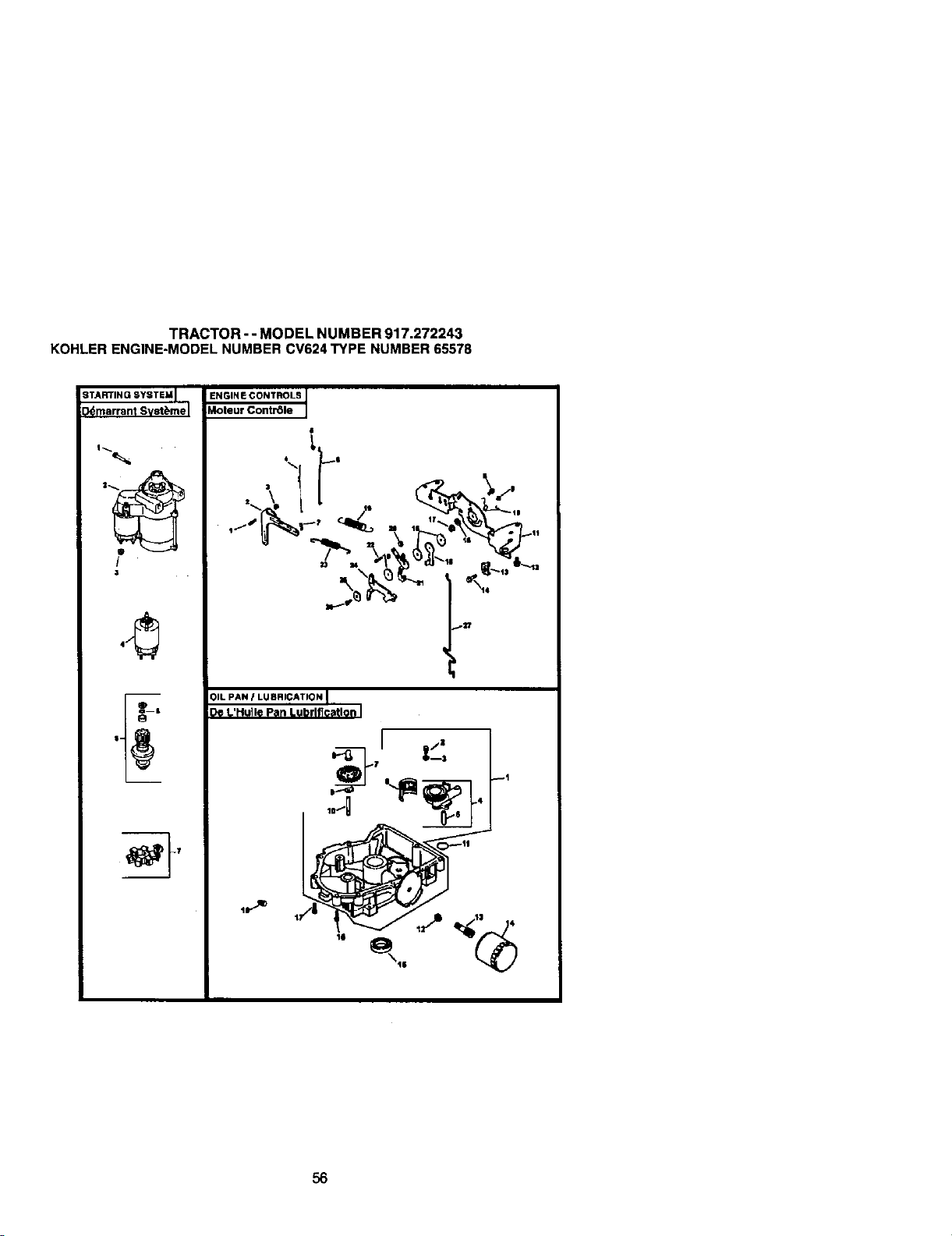
TRACTOR- - MODEL NUMBER 917.272243
KOHLERENGINE-MODELNUMBERCV624TYPE NUMBER65578
STARTING SYSTEM I
I_marrant Svst_me I
!
3
ENGINE CONTROLS
Moteut Contr61e
I
I
4 _t
01LPAN I LUBRICATION I
De L'HuIle Pan Lubrlficatlon I
q
_7
56
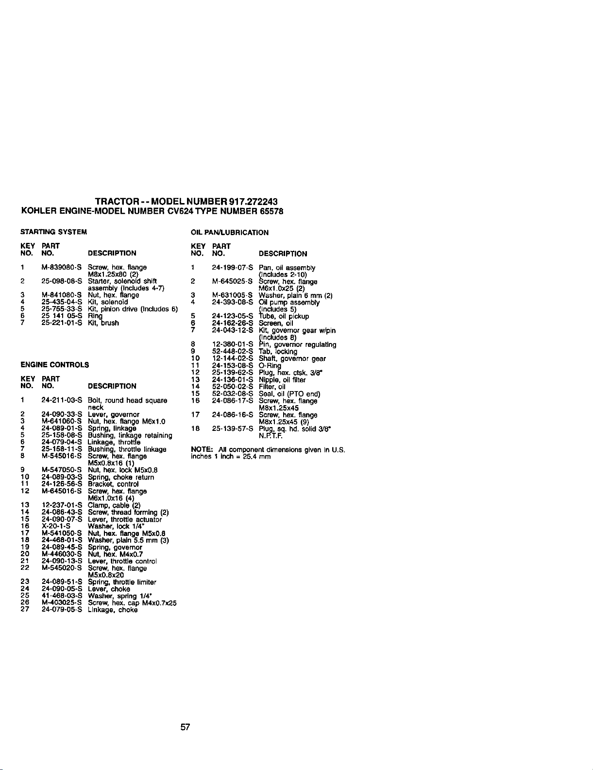
TRACTOR- - MODEL NUMBER 917.272243
KOHLER ENGINE-MODELNUMBERCV624TYPE NUMBER65578
STARING SYSTEM
OIL PAN/LUBRICATION
KEY PART KEY PART
NO. NO. DESCRIPTION NO. NO. DESCRIPTION
1 24-199-07-S
1 M-839080-S Screw, hex. flange
MEx1.25xE0 2)
2 25-098-0E-S Starter, s_eno d sh ft 2
aSSembly _.lncludes 4-7)
3 M-841080-S Nut, hex..ange 3
4 25-435-04-S Kit, sotenoid 4
5 25-755-33-S Kit, pinion drive (includes 6)
6 25 141 05-S Ring 5
7 25-221-01-S Kit,-brush 6
7
ENGINE CONTROLS
KEY PART
NO, NO, DESCRIPTION
1 24-211-03-S _,ott, round head square
neck
2 24-090-33-S Lever, governor
3 M-541060-S Nut, hex. llange M6_1.0
4 24-089-01-S Spring linkage
5 25-158-08-S Bushing, linkelgeretaining
6 24_079-04-S Linkage, throffie
7 25_158-11-S Bushing, throttle linkage
8 M-545016-S Screw,hex. flange
MSx0,Ex16 (1)
9 M-547050-S Nut, hex. lock M5x0.8
10 24-089-03-S 5pdng, choke return
11 24°126-56-S Bracket, control
12 M-645016-S Screw, hex. flange
M6x1.0x16 (4)
13 12-237-01-S Clamp, cable (2)
14 24-086-43-S Screw,thread forming(2)
15 24-090-07-S L_ver, thro_e _ct'J_tor
16 X-20-1-S Washer, lock 1_
17 M-541050-S Nut, hex. flange MSx0.8
t 8 24-468-01-S Washer, plath 5.5 mm (3)
19 24-089-45-S Spring, governor
20 M-446030-S Nut, hex. M4x0.7
21 24-090-13-S Lever, throttlecontrol
22 M-545020-S Screw, hex. flange
M5x0.Ex20
23 24-089-51-S Spdng,throttlelimifer
24 24-090-05-S Lever, choke
25 41-468-03-S Washer, spdng 1/4"
26 M-403025-S Screw, hex. cap M4x0.7x25
27 24-079-05-S Linkage, choke
8
g
10
11
12
13
14
15
16
17
18
Pan, oil assernbty
(includes 2-10)
M-645025-S Screw,hex. flange
M6x1.0x25 2)
M-631005-S Washer, plain 6 mm (2)
24-353-0E-S OU pump assembly
(Includes 5)
24-123-05-S Tube, oil pickup
24-162-26-S Screen, oil
24-043-12-S Kit, governor gear w/pin
(Includes5)
12-380-01-S Pin, governor regulating
52-448-02-S Tab, Icoklng
12.144-02-S Shaft, governor gear
24-153-08-S O-RIng
25-139-62-S Plug, F_ex.ctsk.3/8"
24-136-01-S Nipple,oil filter
52-050-02-S Filter,oil
52-032-08-S Seal, oil (PTO end)
24-Q86-t7-S Screw, hex. flange
M8x1.25x45
24-086-16-5 Screw, hex. flange
ME_1.25x45 (97
25-139-57-S Plug, sq. hd. solid3/5"
N.RT.IE
NOTE: All component dimensionsgiven In U.S.
inches 1 inch = 25.4 rnm
57
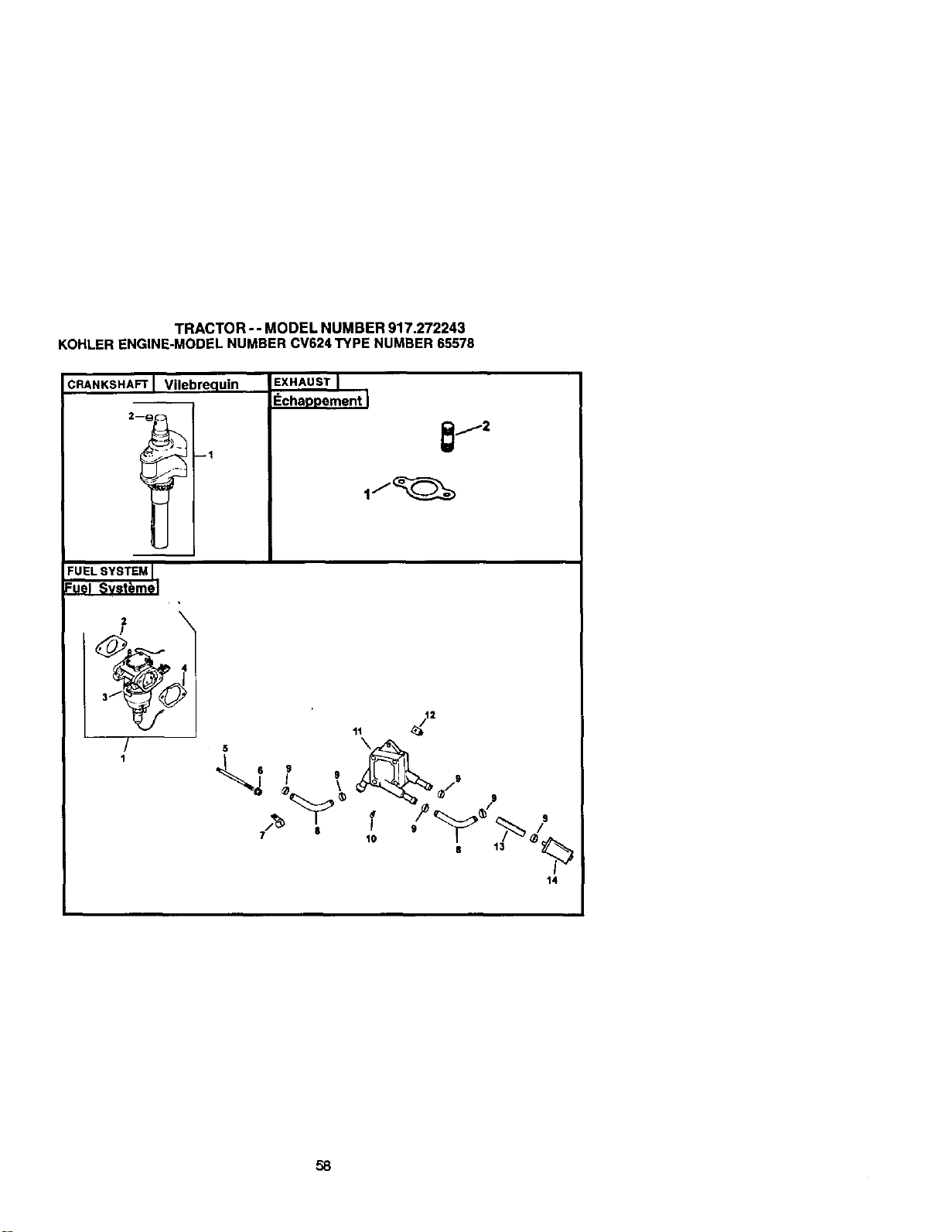
TRACTOR- - MODEL NUMBER 917.272243
KOHLERENGINE-MODELNUMBERCV624TYPE NUMBER65578
CRANKSHAFT Vilebrequin
2--_ --1
i
EXHAUST
Echappement I
_j2
FUELSYSTEMI
=uel Svst_mel
I
/
1
<._, .
14
58
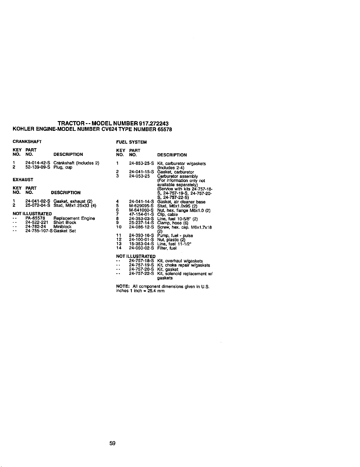
TRACTOR-- MODEL NUMBER 917.272243
KOHLERENGINE-MODELNUMBERCV624TYPE NUMBER65578
CRANKSHAFT FUEL SYSTEM
KEY PART KEY PART
NO. NO. DESCRIPTION NO. NO. DESCRIPT]ON
1 24-014-42-5 Crankshaft (Includes 2) 1 24-553-25-S Kit, carburetor w/gaskets
(Includes 2-4)
2 52-139-09-S Plug, cup 2 24-041-15-S Gasket, carburetor
3 24-053-25 Carburetor assembly
EXHAUST (For information only not
available separately)
KEY PART (_ ePAce with kits 24-757-18-
NO. NO. DESCRIPTION S, 24-757-19-S, 24-757-20-
S, 24-757-22-S)
1 24-041-02-S Gasket, exhaust (2) 4 24-041-14-S Gasket, air cleaner base
2 25-072-04-S Stud, MEx1.25x33 (4) 5 M-629095-S Stud, MSx1.0x95 (2)
6 M-641060-S Nut, hex. flange M6xl.0 (2)
NOT ILLUSTRATED 7 47.154-01-S Clip, cable
- - PA-6557E Replacement Engine 8 24-353-O3-S LIP_, f_lel 10-5/8" (2)
-- 24-522-221 Short 8lock 9 25-237-14-S Clamp, hose (6)
-- 24-782-24 Miniblock 10 24-086-12-S Screw, hex. cap. M6xt.Txt8
-- 24-755-107-S Gasket Set (;)
11 24-393-15-S Pump, fuel -pulse
12 24-100-01-S Nut. plastic (2)
13 15-353-04-S Line, fuel 11-1/2"
14 24-050-02-S Filter, fuel
NOT ILLUSTRATED
-- 24-757-18-S Kit, overhaul w/gaskets
- - 24-757-19-S Kit, choke repair w/gaskets
-- 24-757-20-S Kit, gasket
-- 24-757-22-S Kit, solenoidreplacementw/
gaskets
NOTE: All componentdimensionsgiven in U.S.
inches 1 inch = 25.4 turn
59


61


SUGGESTED GUIDE FOR SIGHTING SLOPES FOR SAFE OPERATION
GUIDE
ONLY RIDE UP AND DOWN HILL,
NOT ACROSS HILL
I_ Operate your Tractor up and down the face of slopes (not
I
greater than 15 ), never across the face. Make turns gradu-
I
ally to prevent tipping or loss of control. Exercise extreme
caution when changing direction on slopes.

Forrepairofmajor brandappr_ancesIn yourown home...
nomatterwhomade it,no matterwhosoldit!
WWW,_QI_,(XXI"I Wm
Forrepairofcarry-inproductslikevacuums,lawnequipment,and
electronics,callforthenearestSearsPartsand RepairCenter.
1-800-488-1222 ,_pme,dayorn_t(U.SAo_)
wm
Forthereplacementparts,accessoriesandownersmanuals
thatyouneed todo-it-yourself,callSearsPartsDirecP'!
1-800-366-PART
(1-8oo-,366-7278)
6am.-11p.m., 7daysa _eek
(usa ub,y)
To purchaseor inquireabouta SearsServiceAgreement
orSearsMaintenanceAgreement:
1-800-827-6655 (U.SA) 1-800-361-6665 (C=-ada)
7a.m.- 5p.m.,CST, Mort.- Sat. 9 a-m.- 8 p.m.EST, M- F,4 p.m.Sal.
Parapetitsewiciodere_ a
domiciio,ypara on:Jenarpiez_:
1.888-SU.HOGARs-
0-sse:r_4-6427)
AuCanadapourseri£eenfran_b:
1-800.LE-IFOYER"c
(1.a_-533-6m7)
www,s_Ban;.(_l
©Se_ RcebJ_andC_
® Registered Trademark I TMTrademark / suService Mark of Sears, Roebuck and Co.
® Marca Registreda / TM Mam..ade F_tbnca/ sa Mama de Senacio de Sears, Roebuck and Co.
uc Marque de commerce / MOMarque d_pos6e de Sears, Roebuck and Co.
179425 4.30.01 JH Printedin U.S.A.


