
Operator's Manual
P R 0 F E S S I 0 N A
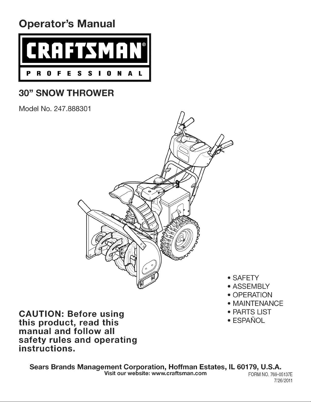
30" SNOW THROWER
Model No. 247.888301
CAUTION: Before using
this product, read this
manual and follow all
safety rules and operating
instructions.
o SAFETY
ASSEMBLY
OPERATION
MAINTENANCE
PARTS LIST
o ESPANOL
Sears Brands Management Corporation, Hoffman Estates, IL 60179, U.S.A.
Visit our website: www.craftsman.com FORM1/O.769-05137E
7/26/2011
WarrantyStatement.................... Page2
SafeOperationPractices.............. Pages3-6
Assembly......................... Pages8-13
Operation........................ Pages14-17
Service&Maintenance.............. Pages18-23
Off-SeasonStorage................... Page24
Troubleshooting...................... Page25
PartsList......................... Pages26-41
RepairProtectionAgreement............ Page45
Espadol............................. Page46
ServiceNumbers................... BackPage
CRAFTSMANPROFESSIONAL TWO YEAR FULL WARRANTY
FORTWOYEARSfromthe dateof purchase,this productis warrantedagainstanydefectsin materialor workmanship.Defectiveproductwill
receivefree repairor free replacementif repairis unavailable.
Thiswarrantyappliesfor onlyone yearfromthe dateof purchaseif this productis everusedwhileprovidingcommercialservicesor if rentedto
anotherperson.
Forwarranty coveragedetails to obtain repairor replacement,visitthe web site: www.craftsman.com
This warrantycovers ONLYdefects in material and workmanship.Warranty coverage does not include:
• Expendableitemsthatcan wearoutfromnormalusewithinthewarrantyperiod,includingbut not limitedto augers,augerpaddles,drift
cutters,skidshoes,shaveplate,shearpins,sparkplug,air cleaner,belts,andoil filter.
• Standardmaintenanceservicing,oilchanges,or tune-ups.
• Tire replacementor repaircausedby puncturesfrom outsideobjects,suchas nails,thorns,stumps,or glass.
Tireor wheelreplacementor repairresultingfromnormalwear,accident,orimproperoperationor maintenance.
Repairsnecessarybecauseof operatorabuse,includingbutnot limitedto damagecausedby over-speedingthe engine,or fromimpacting
objectsthat bendthe frame,auger shaft,etc.
• Repairsnecessarybecauseof operatornegligence,includingbut not limitedto,electricalandmechanicaldamagecausedby improper
storage,failureto usethe propergradeandamountof engineoil, or failureto maintainthe equipmentaccordingto the instructionscontained
inthe operator'smanual.
• Engine(fuelsystem)cleaningor repairscausedbyfuel determinedto be contaminatedor oxidized(stale).In general,fuel shouldbe used
within30 daysof itspurchasedate.
Normaldeteriorationandwearof the exteriorfinishes,or productlabel replacement.
Thiswarrantygivesyou specificlegalrights,andyou mayalso haveotherrightswhichvaryfromstateto state.
Sears Brands Management Corporation, Hoffman Estates, IL 60179
EngineOilType: SAE5W-30
EngineOilCapacity: 37ounces
FuelCapacity: Approx.5Quarts
SparkPlug: F6RTC
SparkPlugGap: .020"to .030"
Model Number.................................................................
Serial Number .................................................................
Dateof Purchase .............................................................
Recordthe modelnumber,serialnumber
anddateof purchaseabove
© KCD IR LLC
2
Thissymbolpointsout importantsafetyinstructionswhich,if not
followed,couldendangerthepersonalsafetyand/orpropertyof
yourselfandothers. Readandfollowall instructionsin this manual
beforeattemptingto operatethismachine.Failureto complywith
theseinstructionsmay resultin personalinjury.Whenyou seethis
symbol,HEEDITSWARNING!
CALIFORNIA PROPOSITION 65
EngineExhaust,someof its constituents,andcertainvehicle
componentscontainor emit chemicalsknownto Stateof California
to causecancerandbirthdefectsorotherreproductiveharm,
Thismachinewasbuiltto beoperatedaccordingto the safeopera-
tion practicesinthis manual.As with anytype of powerequipment,
carelessnessor error on the partof the operatorcan resultin serious
injury.Thismachineis capableof amputatingfingers,hands,toes
andfeetandthrowingdebris.Failureto observethe followingsafety
instructionscouldresultin seriousinjuryor death.
Your Responsibility--Restrict the use of thispowermachineto
personswho read,understandandfollowthewarningsand instruc-
tionsin this manualand on the machine,
SAVE THESE INSTRUCTIONS!
TRAiNiNG
• Read,understand,andfollowall instructionson the machineand
in themanual(s)beforeattemptingto assembleand operate.
Failureto do socan resultin serious injuryto the operatorand/
orbystanders.Keepthismanualin a safeplaceforfutureand
regularreferenceand for orderingreplacementparts.
• Befamiliarwithall controlsand their properoperation.Knowhow
to stopthe machineanddisengagethemquickly.
• Neverallowchildrenunder14yearsof ageto operatethis
machine.Children14andover shouldreadandunderstandthe
instructionsand safe operationpracticesin thismanualandon
the machineandbe trainedand supervisedby an adult.
Neverallowadultsto operatethis machinewithoutproper
instruction.
• Thrownobjectscan causeseriouspersonalinjury.Planyour
snow-throwingpatternto avoiddischargeof materialtoward
roads,bystandersand the like.
Keepbystanders,pets and childrenat least75feetfromthe
machinewhile it is in operation.Stopmachineif anyoneenters
the area.
• Exercisecautionto avoidslippingor falling,especiallywhen
operatingin reverse.
PREPARATION
Thoroughlyinspectthearea wherethe equipmentisto be used.
Removeall doormats,newspapers,sleds,boards,wires and other
foreignobjects,whichcouldbe trippedoveror thrownby the auger/
impeller.
• Alwayswear safetyglassesor eyeshieldsduringoperationand
while performingan adjustmentor repairto protectyoureyes.
Thrownobjectswhichricochetcancauseseriousinjuryto the
eyes.
Donot operatewithoutwearingadequatewinteroutergarments.
Donot wearjewelry,longscarvesorotherlooseclothing,which
could becomeentangledin movingparts.Wearfootwearwhich
will improvefootingonslipperysurfaces.
Usea groundedthree-wireextensioncordand receptaclefor all
machineswith electricstartengines.
Disengageall controlleversbeforestartingthe engine.
Adjustcollectorhousingheightto cleargravelorcrushedrock
surfaces.
• Neverattemptto make anyadjustmentswhileengineis running,
exceptwherespecificallyrecommendedinthe operator'smanual.
Letengineandmachineadjustto outdoortemperaturebefore
startingto clearsnow.
3
Safe Handling of Gasoline
Toavoidpersonalinjuryor propertydamageuseextremecare in
handlinggasoline.Gasolineis extremelyflammableandthe vaporsare
explosive.Seriouspersonalinjurycan occurwhengasolineis spilled
onyourselfor yourclotheswhichcan ignite.Washyour skin and
changeclothesimmediately.
• Useonly an approvedgasolinecontainer.
• Extinguishall cigarettes,cigars,pipesandother sources
of ignition.
• Neverfuelmachineindoors.
• Neverremovegas capor addfuel whilethe engineis hot
or running.
• Allowengine to coolat leasttwo minutesbeforerefueling.
• Neveroverfill fueltank. Filltankto no morethan1/2inch
belowbottomof filler neckto providespacefor fuel
expansion.
• Replacegasolinecap and tightensecurely.
• If gasolineis spilled,wipeit off the engineand equipment.
Movemachineto anotherarea.Wait5 minutesbefore
startingthe engine.
• Neverstorethe machineor fuel containerinsidewhere
thereis anopenflame,sparkor pilotlight (e.g.furnace,
waterheater,spaceheater,clothesdryer etc.).
• Allowmachineto cool at least5 minutesbeforestoring.
• Neverfill containersinsidea vehicleor ona truckor trailer
bedwitha plasticliner.Alwaysplacecontainerson the
groundawayfromyourvehiclebeforefilling.
• If possible,removegas-poweredequipmentfrom thetruck
ortrailerand refuelit on the ground.If this is not possible,
then refuelsuchequipmenton a trailerwitha portable
container,ratherthan from a gasolinedispensernozzle.
• Keepthe nozzlein contactwith the rimof the fueltank or
containeropeningat alltimesuntil fuelingis complete.Do
notuse a nozzlelock-opendevice.
OPERATION
• Do not puthandsorfeetnear rotatingparts,in the auger/impeller
housingor chuteassembly.Contactwiththe rotatingpartscan
amputatehandsandfeet.
• Theauger/impellercontrolleveris a safetydevice.Neverbypass
itsoperation.Doingso makesthe machineunsafeandmaycause
personalinjury.
• Thecontrolleversmustoperateeasilyin bothdirectionsand
automaticallyreturnto the disengagedpositionwhenreleased.
• Neveroperatewitha missingor damagedchuteassembly.Keep
all safetydevicesin placeandworking.
• Neverrunanengineindoorsor in a poorlyventilatedarea. Engine
exhaustcontainscarbonmonoxide,an odorlessanddeadlygas.
• Do notoperatemachinewhileunderthe influenceof alcoholor
drugs.
• Mufflerandenginebecomehotandcan causea burn.Do not
touch.Keepchildrenaway.
• Exerciseextremecautionwhenoperatingon or crossinggravel
surfaces.Stayalertfor hiddenhazardsor traffic.
• Exercisecautionwhenchangingdirectionandwhileoperatingon
slopes.Do notoperateon steep slopes.
• Planyoursnow-throwingpatternto avoiddischargetowards
windows,walls,carsetc. Thus,avoidingpossibleproperty
damageor personalinjurycausedby a ricochet.
• Neverdirect dischargeat children,bystandersand petsor allow
anyoneinfrontof the machine.
• Donot overloadmachinecapacityby attemptingto clearsnowat
too fastof a rate.
• Neveroperatethis machinewithoutgoodvisibility or light. Always
be sureof yourfootingand keepa firm hold on the handles.Walk,
neverrun.
• Disengagepowerto theauger/impellerwhentransportingor not
in use.
• Neveroperatemachineat high transportspeedson slippery
surfaces.Lookdownand behindand usecare whenbackingup.
• If the machineshouldstart to vibrateabnormally,stopthe engine,
disconnectthe sparkplugwire andgroundit againstthe engine.
Inspectthoroughlyfor damage.Repairanydamagebefore
startingandoperating.
• Disengageall controlleversandstopenginebeforeyouleave
the operatingposition(behindthe handles).Wait untilthe auger/
impellercomesto a completestop beforeuncloggingthechute
assembly,makingany adjustments,or inspections.
• Neverput yourhand in the dischargeor collectoropenings.Do
not unclogchuteassemblywhileengineis running.Shutoff
engineand remainbehindhandlesuntilall movingparts have
stoppedbeforeunclogging.
• Useonly attachmentsand accessoriesapprovedby the manufac-
turer (e.g.wheelweights,tire chains,cabsetc.).
• Whenstartingengine,pullcord slowlyuntilresistanceis felt, then
pull rapidly.Rapidretractionof startercord(kickback)will pull
handandarmtowardenginefasterthan youcan let go. Broken
bones,fractures,bruisesor sprainscould result.
• If situationsoccur whichare notcoveredinthis manual,use care
andgoodjudgment.
• Forin-warrantysafety,operationor maintenancequestions,or to
orderpartsandscheduleservice,call 1-800-4-MY-HOME.
CLEARING A CLOGGED DISCHARGE CHUTE
Handcontactwiththe rotatingimpellerinsidethe dischargechute
is the mostcommoncauseof injuryassociatedwithsnowthrowers.
Neveruse yourhandto cleanout thedischargechute.
Toclear thechute:
1. SHUTTHEENGINEOFF!
2. Wait 10secondsto be surethe impellerbladeshavestopped
rotating.
3. Alwaysusea clean-outtool,not yourhands.
4
MAINTENANCE & STORAGE
• Nevertamperwithsafetydevices.Checktheirproperoperation
regularly.Referto the maintenanceand adjustmentsectionsof
thismanual.
• Beforecleaning,repairing,or inspectingmachinedisengageall
controlleversandstopthe engine.Waituntilthe auger/impeller
cometo a completestop.Disconnectthe sparkplugwireand
groundagainsttheengineto preventunintendedstarting.
Checkboltsand screwsfor propertightnessat frequentintervals
to keepthe machineinsafeworkingcondition.Also,visually
inspectmachinefor anydamage.
Do notchangetheenginegovernorsettingor over-speedthe
engine.Thegovernorcontrolsthe maximumsafeoperatingspeed
of the engine.
Snowthrowershaveplatesand skid shoesare subjectto wear
anddamage.Foryoursafetyprotection,frequentlycheckall
componentsand replacewith originalequipmentmanufacturer's
(OEM)partsonlyas listedinthe Partspagesof thisoperator's
manual.Useof partswhichdonot meetthe originalequipment
specificationsmayleadto improperperformanceand compro-
misesafety!
Checkcontrolleversperiodicallyto verifytheyengageanddisen-
gageproperlyandadjust,if necessary.Referto the adjustment
sectioninthisoperator'smanualfor instructions.
Maintainor replacesafetyand instructionlabels,as necessary.
Observeproperdisposallawsand regulationsfor gas, oil,etc. to
protectthe environment.
Priorto storing,runmachinea few minutestoclear snowfrom
machineand preventfreezeup of auger/impeller.
Neverstorethe machineorfuel containerinsidewherethereisan
openflame,sparkorpilot lightsuchas a waterheater,furnace,
clothesdryer etc.
Alwaysreferto the operator'smanualfor properinstructionson
off-seasonstorage.
Checkfuelline,tank, cap,andfittingsfrequentlyfor cracksor
leaks.Replaceif necessary.
Do notcrankenginewithsparkplugremoved.
Accordingto the ConsumerProductsSafetyCommission(CPSC)
andthe U.S.EnvironmentalProtectionAgency(EPA),thisproduct
hasan AverageUsefulLifeof seven(7) years,or 60 hoursof
operation.At the endof theAverageUsefulLifehavethe machine
inspectedannuallybyan authorizedservicedealer to ensurethat
allmechanicalandsafetysystemsare workingproperlyand not
wornexcessively.Failureto do so can resultin accidents,injuries
ordeath.
DO NOT MODIFY ENGINE
Toavoidseriousinjuryor death,do not modifyengineinany way.
Tamperingwiththe governorsettingcanleadto a runawayengineand
causeit to operateat unsafespeeds.Nevertamperwithfactorysetting
of enginegovernor.
NOTICE REGARDING EMiSSiONS
Engineswhich are certifiedtocomplywith Californiaand federal
EPAemissionregulationsfor SORE(SmallOff RoadEquipment)are
certifiedto operateon regularunleadedgasoline,and mayinclude
the followingemissioncontrolsystems:EngineModification(EM),
OxidizingCatalyst(OC),SecondaryAir Injection(SAI)and ThreeWay
Catalyst(TWO)if so equipped.
SPARK ARRESTOR
Thismachineisequippedwithaninternalcombustionengineand
shouldnotbe usedon or nearany unimprovedforest-covered,
brush-coveredor grass-coveredland unlessthe engine'sexhaust
systemisequippedwitha sparkarrestormeetingapplicablelocalor
statelaws(if any)
Ifa sparkarrestoris used, it shouldbe maintainedin effectiveworking
orderby theoperator.Inthe Stateof Californiathe aboveis required
bylaw (Section4442of the CaliforniaPublicResourcesCode).Other
statesmayhavesimilarlaws. Federallawsapplyonfederallands.
A spark arrestorfor the muffleris availablethroughyournearestSears
PartsandRepairServiceCenter.
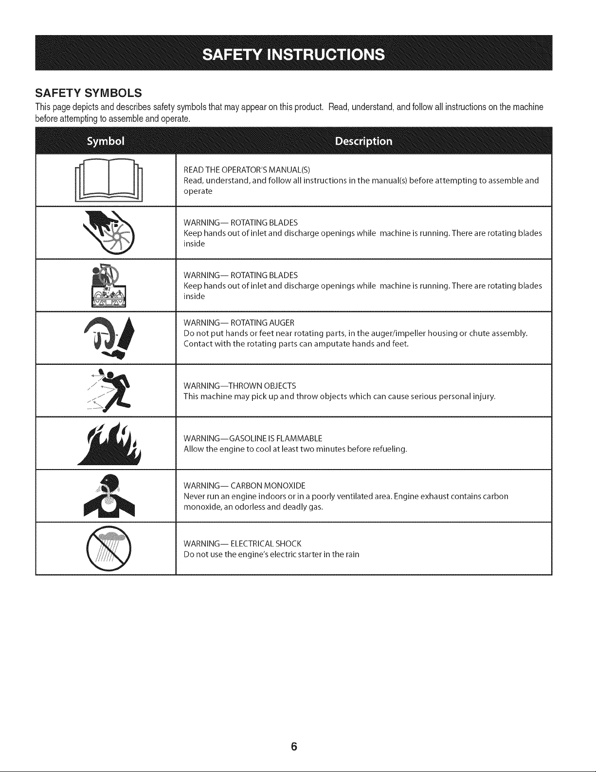
SAFETY SYMBOLS
Thispagedepictsanddescribessafetysymbolsthat mayappear on this product. Read,understand,andfollowall instructionson the machine
beforeattemptingto assembleandoperate.
. +
i
i
"JIp
READ THE OPERATOR'S MANUAL(S)
Read, understand, and follow all instructions in the manual(s) before attempting to assemble and
operate
WARNING-- ROTATING BLADES
Keep hands out of inlet and discharge openings while machine is running. There are rotating blades
inside
WARNING-- ROTATING BLADES
Keep hands out of inlet and discharge openings while machine is running. There are rotating blades
inside
WARNING-- ROTATING AUGER
Do not put hands or feet near rotating parts, in the auger/impeller housing or chute assembly.
Contact with the rotating parts can amputate hands and feet.
WARNING--THROWN OBJECTS
This machine may pick up and throw objects which can cause serious personal injury.
WARNING--GASOLINE IS FLAMMABLE
Allow the engine to cool at least two minutes before refueling.
WARNING-- CARBON MONOXIDE
Never run an engine indoors or in a poorly ventilated area. Engine exhaust contains carbon
monoxide, an odorless and deadly gas+
WARNING-- ELECTRICAL SHOCK
Do not use the engine's electric starter in the rain
6

Thispageleftintentionallyblank.
7
NOTE:Referencesto rightorleft sideof the snowthrowerare
determinedfrombehindthe unit inthe operatingposition(standing
directlybehindthe snowthrower,facingthe handlepanel).
REMOVING FROM CARTON
1. Cut the cornersof thecarton and lay the sidesflat on the ground.
Removeand discard all packinginserts.
2. Movethe snowthrowerout of thecarton.
3. Makecertainthe carton has beencompletelyemptiedbefore
discardingit.
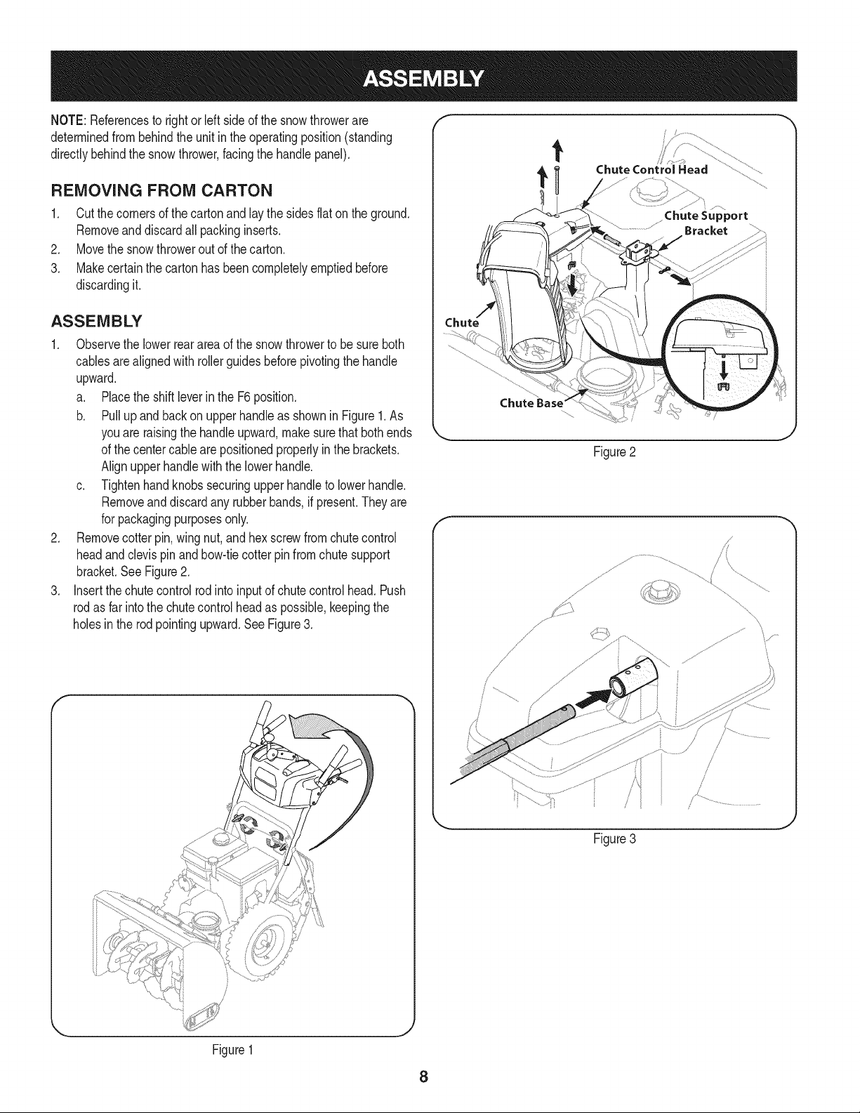
ASSEMBLY
1. Observethe lowerreararea of the snowthrowerto be sure both
cablesarealignedwith rollerguidesbeforepivotingthe handle
upward.
a. Placethe shiftleverin the F6position.
b. Pull up and back on upperhandleas shownin Figure1.As
youare raisingthe handleupward,make surethat bothends
of the centercablearepositionedproperlyinthe brackets.
Alignupperhandlewiththe lowerhandle.
c. Tightenhandknobssecuringupper handleto lowerhandle.
Removeand discard any rubberbands,if present.Theyare
for packagingpurposesonly.
2. Removecotterpin,wing nut, and hexscrewfrom chutecontrol
headand clevispin and bow-tiecotterpin from chute support
bracket.SeeFigure2.
3. Insertthe chutecontrolrodintoinputof chutecontrolhead.Push
rodas far intothe chutecontrolheadas possible,keepingthe
holesin the rod pointingupward.See Figure3.
t
Chute Control Head
Chute
Figure2
f
// .....
%
Figure3
Figure1
8
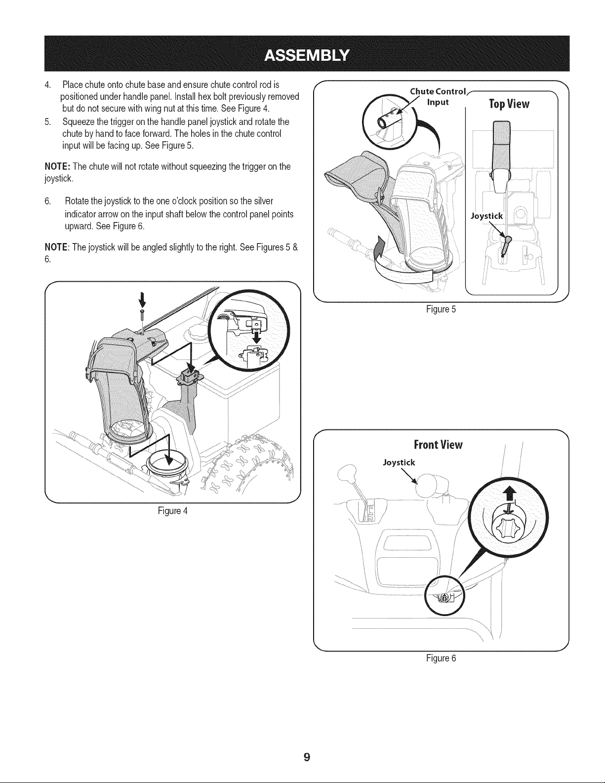
4. Placechuteontochute baseand ensurechutecontrolrodis
positionedunderhandlepanel.Installhex boltpreviouslyremoved
but do notsecurewith wing nutat thistime.See Figure4.
5. Squeezethetriggeron the handlepaneljoystickand rotatethe
chutebyhandto faceforward.The holesinthe chutecontrol
inputwill befacingup. SeeFigure5.
NOTE:The chutewill not rotatewithoutsqueezingthe triggeronthe
joystick.
6. Rotatethejoystickto the oneo'clockpositionso the silver
indicatorarrowonthe inputshaft belowthe controlpanelpoints
upward.SeeFigure6.
NOTE:Thejoystickwillbe angledslightlyto the right.SeeFigures5 &
6.
Figure4
TopView
Figure5
f
FrontView
Joystick
Figure6
J
9
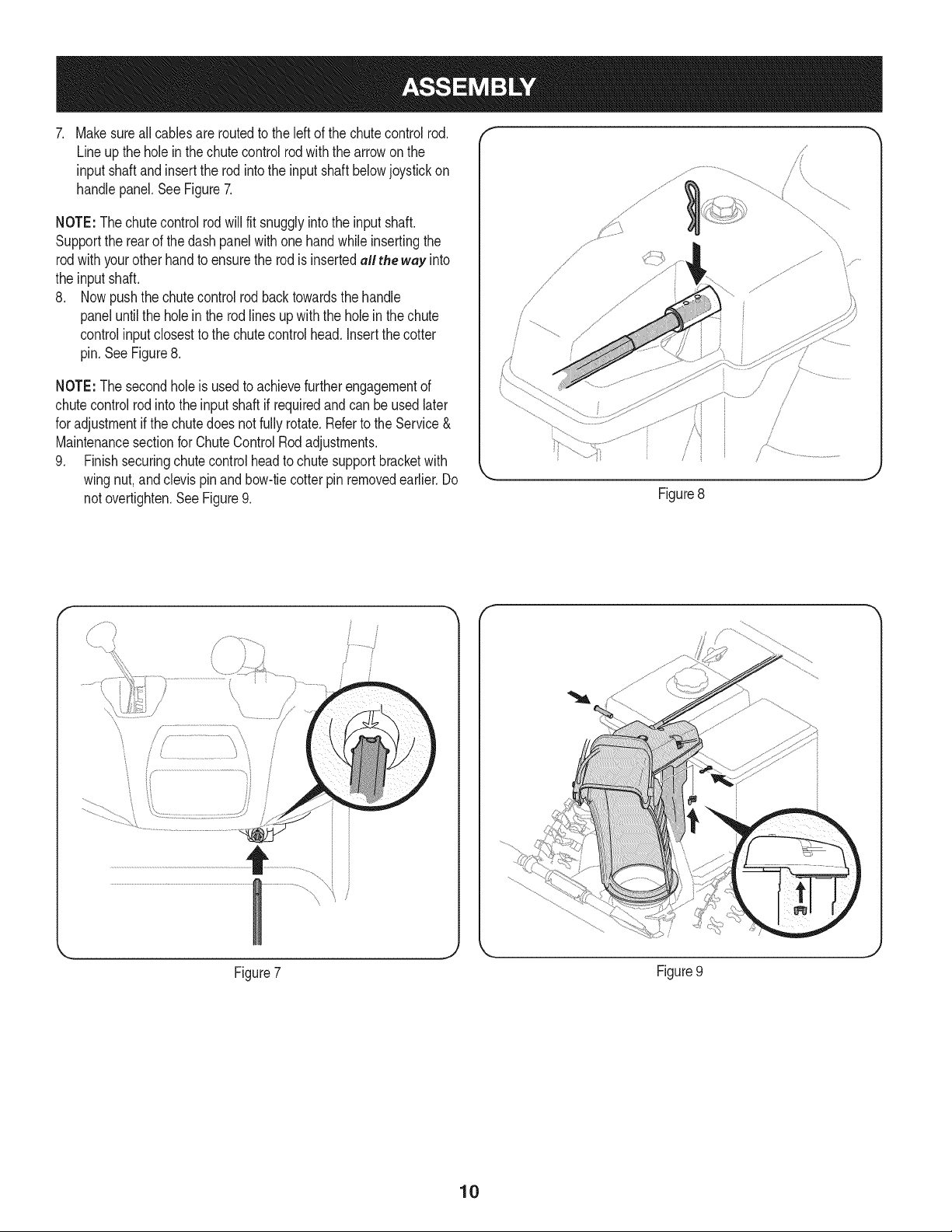
. Makesureall cables are routedto the left of the chutecontrolrod.
Lineupthe holein thechutecontrolrodwiththe arrowonthe
input shaftandinsertthe rodintothe inputshaft belowjoystickon
handlepanel.See Figure7.
NOTE:Thechutecontrolrodwill fit snugglyintothe inputshaft.
Supportthe rearof thedash panelwithone handwhileinsertingthe
rodwithyourotherhandto ensurethe rodis insertedall the way into
the input shaft.
8. Nowpushthe chutecontrolrodbacktowardsthe handle
paneluntilthe holein the rod linesup with the holein the chute
controlinputclosestto the chutecontrolhead. Insertthe cotter
pin.SeeFigure8.
NOTE:The secondholeis usedto achievefurtherengagementof
chutecontrolrod into the inputshaftif requiredand can be usedlater
for adjustmentif the chutedoes not fullyrotate.Referto the Service&
Maintenancesectionfor ChuteControlRodadjustments.
9. Finishsecuringchute controlheadto chutesupportbracketwith
wingnut,andclevispinandbow-tiecotter pinremovedearlier.Do
notovertighten.SeeFigure9.
/
.J
Figure8
\
y..................
Figure7
Figure9
10
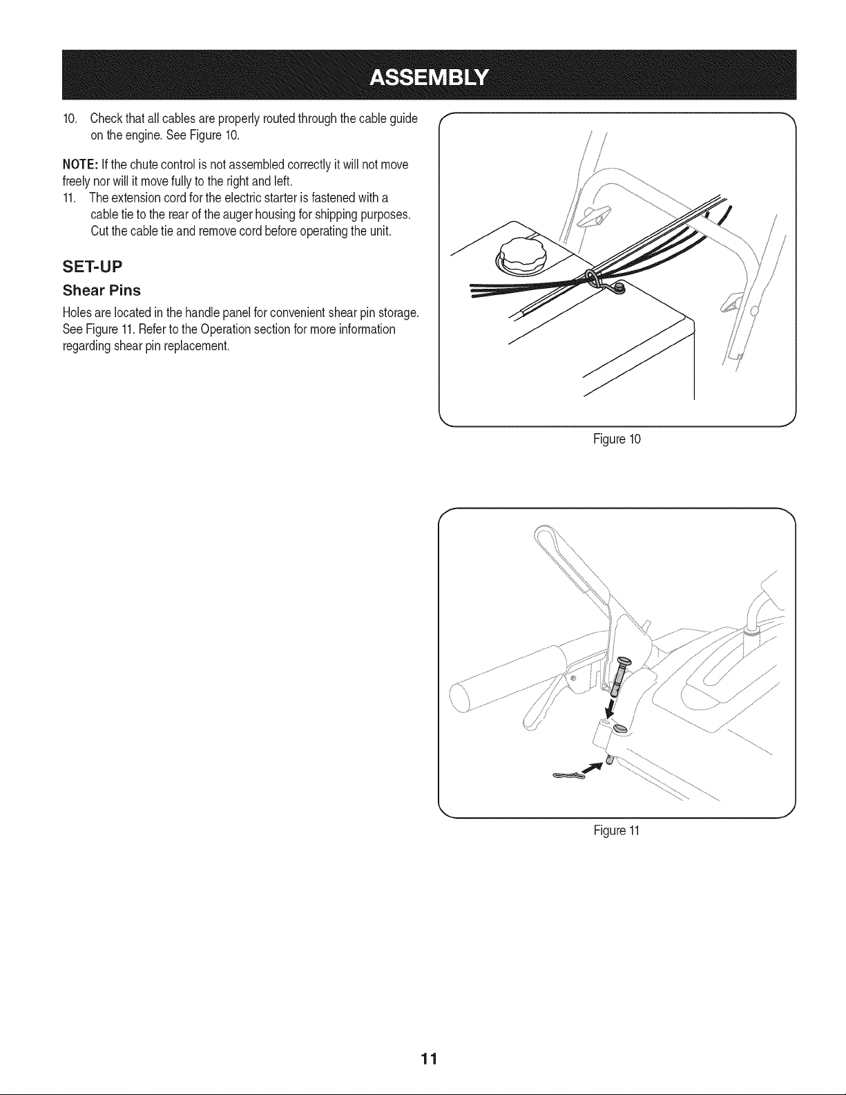
10. Checkthat allcables are properlyroutedthroughthecable guide "_
on theengine.See Figure10.
NOTE: if the chutecontrolis notassembledcorrectlyit will not move
freelynorwill it movefullyto the rightandleft.
11. Theextensioncord forthe electricstarteris fastenedwith a
cabletie to the rearof the augerhousingfor shippingpurposes.
Cutthe cabletie and removecord beforeoperatingthe unit.
SET-UP
Shear Pins
Holesare locatedin the handlepanelfor convenientshearpin storage.
SeeFigure11.Referto the Operationsectionfor moreinformation
regardingshearpin replacement.
/
Figure10
f
Figure11
J
11
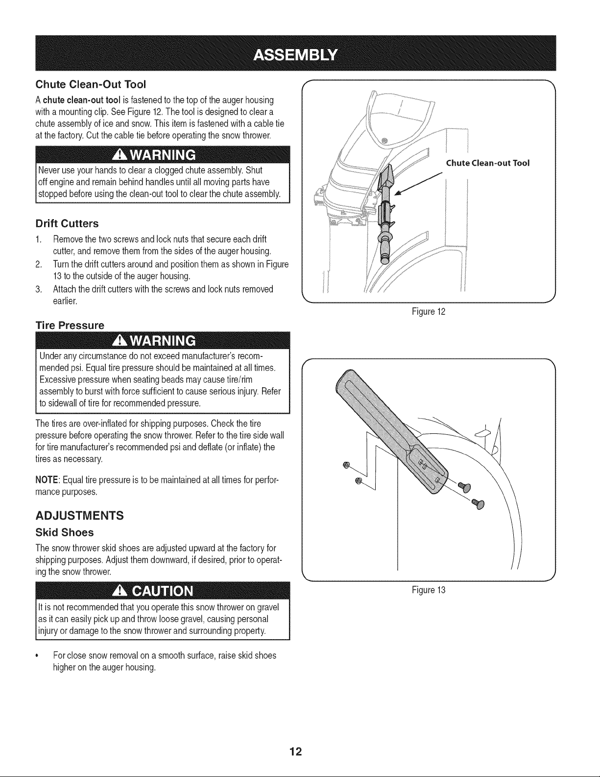
Chute Clean-Out Tool
Achute clean-out tool is fastenedto the top of the augerhousing
witha mountingclip. See Figure12.The tool is designedto cleara
chuteassemblyof ice andsnow.Thisitemis fastenedwitha cabletie
at the factory.Cutthecable tie beforeoperatingthe snowthrower.
loft _1 .allmovingpartshave
stoppedbeforeusingthe clean-outtool to clearthe chuteassembly.
Drift Cutters
1. Removethe two screwsand locknutsthat secureeach drift
cutter,andremovethem from the sidesof the augerhousing.
2. Turnthe drift cutters aroundand positionthemas shown inFigure
13to the outsideof theaugerhousing.
3. Attachthedrift cutterswiththe screwsandlock nuts removed
earlier.
Tire Pressure
Underanycircumstancedo notexceed manufacturer'srecom-
mendedpsi. Equaltire pressureshouldbe maintainedat all times.
Excessivepressurewhenseatingbeadsmaycausetire/rim
assemblyto burstwithforcesufficientto causeseriousinjury.Refer
to sidewallof tirefor recommendedpressure.
Chutedean-out Tool
Figure12
Thetiresareover-inflatedfor shippingpurposes.Checkthetire
pressurebeforeoperatingthe snow thrower.Referto the tire sidewall
for tiremanufacturer'srecommendedpsianddeflate(or inflate)the
tiresas necessary.
NOTE:Equaltire pressureis to be maintainedat all timesfor perfor-
mancepurposes.
ADJUSTMENTS
Skid Shoes
The snowthrowerskidshoesareadjustedupwardat thefactoryfor
shippingpurposes.Adjustthemdownward,ifdesired,priorto operat-
ingthe snowthrower.
It isnot recommendedthatyouoperatethis snowthroweron gravel
as itcan easilypickup andthrowloosegravel,causingpersonal
njuryordamageto the snowthrowerand surroundng property.
• Forclosesnow removalon a smoothsurface,raiseskidshoes
higheronthe augerhousing.
Figure13
12
Usea middleor lowerpositionwhentheareato be clearedis
uneven,suchas a graveldriveway.
NOTE:Ifyou chooseto operatethe snowthroweron a gravelsurface,
keepthe skidshoesin positionfor maximumclearancebetweenthe
groundandthe shaveplate.
Operatinga snowthrowerequippedwith steelskidshoesmayresult
indamageto naturalstonepaversurfaces(e.g.sandstone,blue-
stone,limestone). Forinformationonavailablepolymerskid shoes,
call 1-800-4MY-HOME.
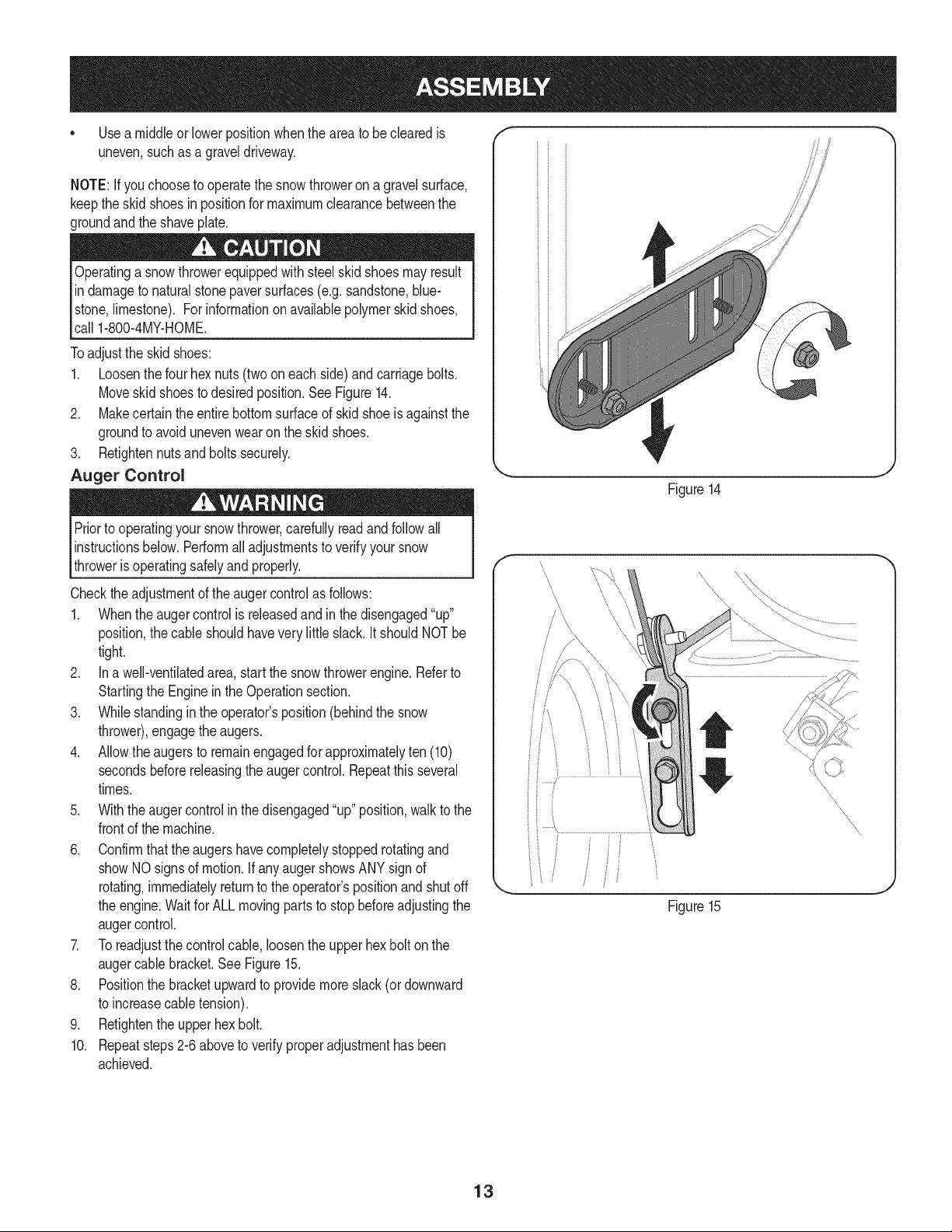
Toadjustthe skidshoes:
1. Loosenthe fourhex nuts(twooneach side)andcarriagebolts.
Moveskidshoesto desiredposition.See Figure14.
2. Makecertain theentirebottomsurfaceof skid shoeis againstthe
groundto avoidunevenwearonthe skidshoes.
3. Retightennutsand bolts securely.
Auger Control
Priorto operatingyoursnowthrower,carefullyreadand followall
instructionsbelow.Performall adjustmentsto verifyyour snow
throweris operatingsafelyand properly.
Checktheadjustmentof the augercontrolas follows:
1. Whentheaugercontrolis releasedand in the disengaged"up"
position,the cableshouldhavevery little slack. It shouldNOTbe
tight.
2. In a well-ventilatedarea,start the snowthrowerengine.Referto
Startingthe Engineinthe Operationsection.
3. Whilestandingin the operator'sposition(behindthe snow
thrower),engagethe augers.
4. Allowtheaugersto remainengagedfor approximatelyten (10)
secondsbeforereleasingthe augercontrol.Repeatthis several
times.
5. With theauger controlin thedisengaged"up" position,walkto the
frontof the machine.
6. Confirmthat the augershavecompletelystoppedrotatingand
showNOsignsof motion.If anyauger showsANY signof
rotating,immediatelyreturnto the operator'spositionand shutoff
the engine.Waitfor ALLmovingpartsto stopbeforeadjustingthe
augercontrol.
7. Toreadjustthecontrolcable, loosentheupper hexbolt on the
augercablebracket.SeeFigure15.
8. Positionthe bracketupwardto providemoreslack(or downward
to increasecabletension).
9. Retightenthe upperhex bolt.
10. Repeatsteps2-6 aboveto verifyproperadjustmenthasbeen
achieved.
Figure14
J
f
f
/
Figure15
J
13
f
Chute Assembly
\
\
\
Drive Control
Headlight
Gas Cap
\
\\\\\
Drift Cutter _ --
t
iFi
Augers
Shift Lever
J _ Four-Way Chute ControP (Joystick)
//_ ...................AugerControl.
y Muffler Handle Oil Fill
Primer \
Choke
Skid Shoe Oil Drain
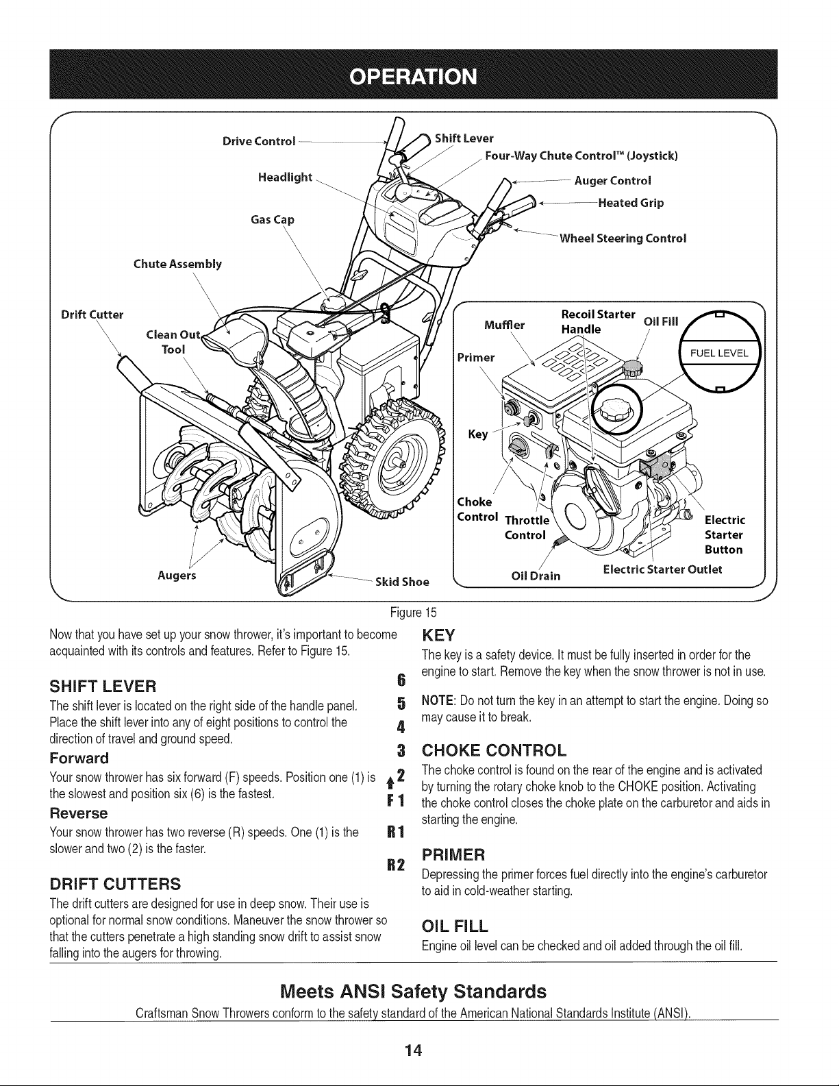
Nowthat youhaveset up yoursnowthrower,it'simportantto become
acquaintedwith its controlsand features.Referto Figure15.
SHIFT LEVER 6
The shiftleverislocatedonthe rightsideof the handlepanel. 5
Placethe shiftleverinto anyof eightpositionsto controlthe 4
directionof travelandgroundspeed,
Forward 3
Yoursnowthrowerhas sixforward(F) speeds.Positionone(1)is t 2
the slowestand positionsix (6) is the fastest. F 1
Reverse
Yoursnowthrowerhastwo reverse(R) speeds.One (1) is the
slowerandtwo (2) is the faster.
DRIFT CUTTERS
Thedrift cuttersare designedfor use in deep snow.Theiruse is
optionalfor normalsnowconditions.Maneuverthe snowthrowerso
thatthe cutterspenetratea highstandingsnowdriftto assistsnow
fallingintothe augersfor throwing.
Figure15
KEY
The keyis a safetydevice.It mustbefullyinsertedinorderfor the
engineto start.Removethe keywhenthe snowthroweris not inuse.
NOTE: Donot turnthe keyinan attemptto startthe engine.Doingso
maycauseit to break.
CHOKE CONTROL
The chokecontrolis foundon the rearof the engineand is activated
by turningthe rotarychokeknobto the CHOKEposition.Activating
the chokecontrolclosesthe chokeplateon thecarburetorand aids in
startingthe engine.
PRIMER
Depressingthe primerforcesfueldirectlyintothe engine'scarburetor
to aid incold-weatherstarting.
OIL FILL
Engineoil levelcan be checkedand oil added throughthe oil fill.
Meets ANSi Safety Standards
CraftsmanSnowThrowersconformto the safetystandardof the AmericanNationalStandardsInstitute(ANSI).
14
THROTTLE CONTROL
Thethrottlecontrolis locatedon the rearof the engine.It regulatesthe
speedof theengineandwill shutoff the enginewhenmovedintothe
STOPposition.
ELECTRIC STARTER BUTTON
Pressingthe electricstarterbuttonengagesthe engine'selectric
starterwhenpluggedintoa 120Vpowersource.
ELECTRIC STARTER OUTLET
Requiresthe useof athree-prongoutdoorextensioncord(included)
anda 120Vpowersource/walloutlet.
AUGERS
Whenengaged,the auger bladesrotateand drawsnowintothe auger
housing.
SKID SHOES
Positionthe skid shoesbasedon surfaceconditions.Adjust upward
for hard-packedsnow.Adjustdownwardwhenoperatingon gravelor
crushedrocksurfaces.
HEADLIGHT
Theheadlightis on whenevertheengine is running.
HEATED GRIPS
Toactivatethe heatedgrips,movethe switchfoundon the rearof the
dashpanelintothe ON position.
WHEEL STEERING CONTROLS
Theleft and rightwheelsteeringcontrolsare locatedon theunderside
of the handles.Squeezethe rightcontrolto turn right; squeezethe left
controlto turn left.
NOTE:Operatethe snowthrowerinopenareasuntilyou arefamiliar
withthesecontrols.
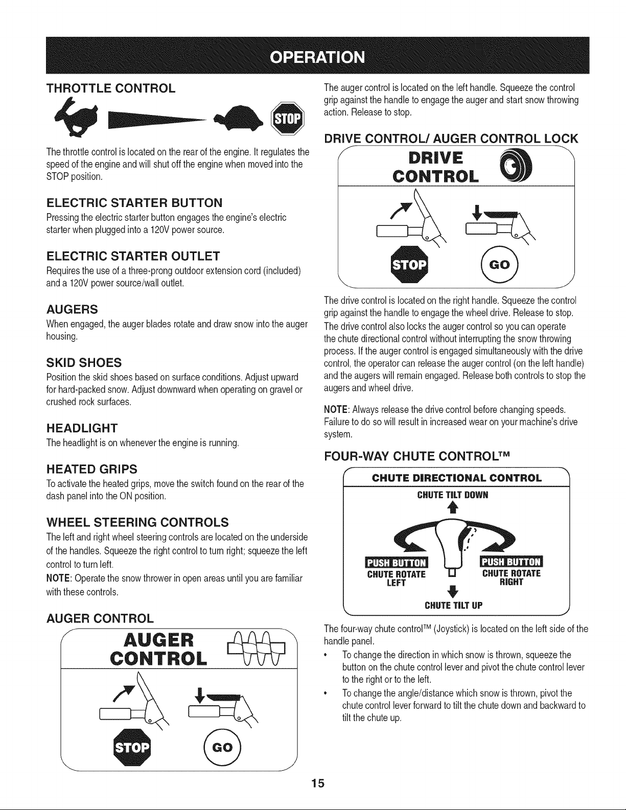
AUGER CONTROL
The augercontrolis locatedon the left handle.Squeezethe control
gripagainstthe handleto engagethe augerand startsnowthrowing
action.Releaseto stop.
DRIVE CONTROL/AUGER CONTROL LOCK
DRIVE
CONTROL
The drivecontrolis locatedon the righthandle.Squeezethe control
gripagainstthe handleto engagethe wheeldrive.Releaseto stop.
The drivecontrolalso lockstheaugercontrolso youcan operate
the chutedirectionalcontrolwithoutinterruptingthe snowthrowing
process.If the augercontrolis engagedsimultaneouslywiththe drive
control,the operatorcan releasethe augercontrol (on the left handle)
andthe augerswill remainengaged.Releaseboth controlsto stopthe
augersandwheeldrive.
NOTE:Alwaysreleasethedrivecontrolbeforechangingspeeds.
Failureto do so will result in increasedwearon yourmachine'sdrive
system.
FOUR=WAY CHUTE CONTROL TM
CHUTE DiRECTiONAL CONTROL
CHUTETiLTDOWN
t
CHUTEROTATE CHUTEROTATE
LEFT RIGHT
CHUTETiLTUP
j,
The four-waychutecontrolTM (Joystick)is locatedon theleft sideof the
handlepanel.
* Tochangethe directionin which snowis thrown,squeezethe
buttononthe chutecontrolleverand pivotthe chutecontrollever
to the rightorto the left.
* Tochangethe angle/distancewhich snow isthrown,pivotthe
chutecontrolleverforwardto tiltthe chutedownand backwardto
tilt the chuteup.
15
CLEAN-OUT TOOL
Neveruseyourhandsto cleara cloggedchuteassembly.Shut
loft engineand remainbehindhandlesuntil all movingparts have
lstoppedbeforeusingtheclean-outtool to clearthe chuteassembly.
Thechuteclean-outtool is convenientlyfastenedto the rearof the
augerhousingwitha mountingclip. Shouldsnowand ice become
lodgedin thechute assemblyduringoperation,proceedas followsto
safelycleanthechuteassemblyandchute opening:
1. Releaseboththe AugerControland the DriveControl.
2. Stopthe engineby removingthe ignitionkey.
3. Removethe clean-outtoolfromthe clip whichsecuresit to the
rearof the augerhousing.
4. Use the shovel-shapedendof theclean-outtool to dislodgeand
scoopany snowand icewhich hasformedin andnearthechute
assembly.
5. Refastenthe clean-outtool to the mountingclip on the rear of
theaugerhousing,reinsertthe ignitionkeyand startthe snow
thrower'sengine.
6. Whilestandingin the operator'sposition(behindthesnow
thrower),engagethe augercontrolfora fewsecondsto clear any
remainingsnowandice fromthechute assembly.
BEFORE STARTING ENGINE
Read,understand,and followall instructionsandwarningson the
machineand in this manualbeforeoperating.
Oil
Theunit wasshippedwith oil in the engine.Checkoil levelbefore
eachoperationto ensureadequateoil inthe engine.Forfurther
instructions,refertothe stepson page 18.
NOTE:Besureto checkthe engineon a levelsurfacewiththe engine
stopped.
1. Removethe oil fillercap/dipstickand wipethe dipstickclean.
2. insertthe cap/dipstickintothe oil filler neck,and tightenthe cap
until seated.
3. Removethe oil fillercap/dipstick,ifthe levelislow,slowlyadd
oil (5%30, with a minimumclassificationof SF/SG)untiloil level
registersbetweenhigh (H) and low(L).
NOTE:Do notoverfill.Overfillingwithoil mayresultinenginesmoking,
hardstartingor spark plugfouling.
4. Replaceand tighten cap/dipstickfirmlybeforestartingengine.
Gasoline
Useautomotivegasoline(unleadedor low leadedto minimizecombus-
tionchamberdeposits)witha minimumof 87octane.Gasolinewith
upto 10%ethanolor 15%MTBE(MethylTertiaryButylEther)canbe
used.Neveruseanoil/gasolinemixtureor dirty gasoline.Avoidgetting
dirt,dust,or waterin thefuel tank. DO NOTuse E85gasoline.
• Refuelin a well-ventilatedareawith the enginestopped.Do not
smokeorallowflamesor sparksin the areawherethe engineis
refueledor wheregasolineisstored.
• Donot overfillthe fueltank.After refueling,makesurethe tank
cap is closedproperlyandsecurely.
• Be carefulnotto spillfuel whenrefueling.Spilledfuel or fuel vapor
mayignite,ifany fuelis spilled,makesurethe areaisdry before
startingthe engine.
• Avoidrepeatedorprolongedcontact with skinor breathingof
)or.
Useextremecarewhen handlinggasoline.Gasolineis extremely
flammableandthevaporsare explosive.Neverfuelthe machine
indoorsorwhilethe engineis hotor running.Extinguishcigarettes,
cigars,pipesandothersourcesof ignition.
1. Cleanaroundfuel fill beforeremovingcap to fuel.
2. A fuel levelindicatoris locatedin the fueltank. SeeFigure15
inset. Becarefulnotto overfill.Filltank untilfuel reachesthe fuel
level indicatorto allowspacefor fuel expansion.
STARTING THE ENGINE
Alwayskeep handsandfeet clearof movingparts. Donot usea
pressurizedstartingfluid.Vaporsare flammable.
NOTE:Allowthe engineto warmupfor a fewminutesafter starting.
The enginewill notdevelopfull poweruntilit reachesoperating
temperatures.
1. Makecertainboththe augercontrol and drivecontrolare in the
disengaged(released)position.
2. insert keyinto slot. Makesureit snapsintoplace. Donot attempt
to turn the key.
NOTE: Theenginecannotstartwithoutthe keyfullyinsertedintothe
ignitionswitch.
Electric Starter
The optionalelectricstarteris equippedwitha groundedthree-wire
powercordandplug,and is designedto operateon 120volt AC
householdcurrent.It mustbe usedwith a properlygroundedthree-
prongreceptacleat all timesto avoidthe possibilityof electricshock.
Followall instructionscarefullypriorto operatingtheelectricstarter.
DONOTuse electricstarterinthe rain.
Determinethat yourhome'swiringis a three-wiregroundedsystem.
Aska licensedelectricianif you are notcertain.
Ifyou havea groundedthree-prongreceptacle,proceedas follows.
Ifyou donot havethe properhousewiring,DONOTusethe electric
starterunderanyconditions.
1. Plugthe extensioncord intothe outletlocatedon the engine's
surface.Plugthe otherendof extensioncord intoa three-prong
120-volt,grounded,AC outletin a well-ventilatedarea.
16
2. Movethrottlecontrolto FAST(rabbit)'_ position.
3. Movechoketo the CHOKE IJl position(coldenginestart). If
engineis warm,placechokein RUNposition.
4. Pushprimerthree (3) times, makingsureto covervent hole in
primerbulbwhen pushing.If engineis warm,pushprimeronly
once.Alwayscoverventhole whenpushing.Coolweathermay
requireprimingto be repeated.
5. Pushstarterbuttonto start engine.Oncethe enginestarts,im-
mediatelyreleasestarterbutton.Electricstarteris equippedwith
thermaloverloadprotection;systemwill temporarilyshut-downto
allowstarterto cool if electricstarterbecomesoverloaded.
6. As theenginewarms,slowlyrotatethe chokecontrol to RUN
position.If the enginefalters,restartengineand run with choke
at half-chokepositionfor a short periodof time,and then slowly
rotatethe chokeinto RUNposition.
7. After engineis running,disconnectpowercordfrom electric
starter.Whendisconnecting,alwaysunplugthe end at the wall
outletbeforeunpluggingtheoppositeend from the engine.
Recoil Starter
TO ENGAGE DRIVE
1. Withthe throttlecontrolinthe Fast(rabbit) position,moveshift
leverinto oneof the sixforward(F) positionsor tworeverse(R)
positions.Selecta speedappropriatefor the snowconditionsand
a paceyou'recomfortablewith.
NOTE: When selectinga DriveSpeed,use the slowerspeedsuntil
you arecomfortableandfamiliarwiththe operationof the snow
thrower.
2. Squeezethe drivecontrolagainstthe handleandthe snow
throwerwill move.Releaseit anddrive motionwill stop.
NOTE:NEVERrepositionthe shiftlever(changespeedsordirection
of travel)withoutfirst releasingthe drivecontrolandbringingthe snow
throwerto a completestop.Doingsowill resultin prematurewearto
the snowthrower'sdrivesystem.
TO ENGAGE AUGER
1. Toengagethe augerand startthrowingsnow,squeezethe auger
controlagainstthe left handle.Releaseto stopthe auger.
Do notpullthe starterhandlewhilethe enginerunning.
1. Movethrottlecontrolto FAST(rabbit)'_ position.
2. Movechoketo the CHOKE I,'_1 position(coldenginestart). If
engineis warm,placechokein RUNposition.
3. Pushprimerthree (3) times, makingsureto covervent hole when
pushing.Ifengine iswarm,push primeronlyonce.Alwayscover
ventholewhen pushing.Coolweathermayrequireprimingto be
repeated.
4. Pull gentlyon the starterhandleuntil it beginsto resist,then
pullquicklyandforcefullyto overcomethe compression.Engine
shouldstart.Donot releasethe handleandallow it to snapback.
ReturnropeSLOWLYto originalposition.If required,repeatthis
step.
5. As theenginewarms,slowlyrotatethe chokecontrol to RUN
position.If the enginefalters,restartengineand run with choke
at half-chokepositionfor a short periodof time,and then slowly
rotatethe chokeinto RUNposition.
To avoidunsupervisedengineoperation,neverleavethe machine
unattendedwiththe enginerunning.Turnthe engineoffafter use and
removekey.
STOPPING THE ENGINE
Afteryouhavefinishedsnow-throwing,run enginefora few minutes
beforestoppingto helpdry offany moistureonthe engine.
1. Movethrottlecontrolto OFFposition.
2. Removethekey.Removingthe keywill reducethe possibilityof
unauthorizedstartingof the enginewhileequipmentis notin use.
Keepthe keyina safe place.The enginecannotstart withoutthe
key.
3. Wipeany moistureawayfromthe controlson theengine.
17
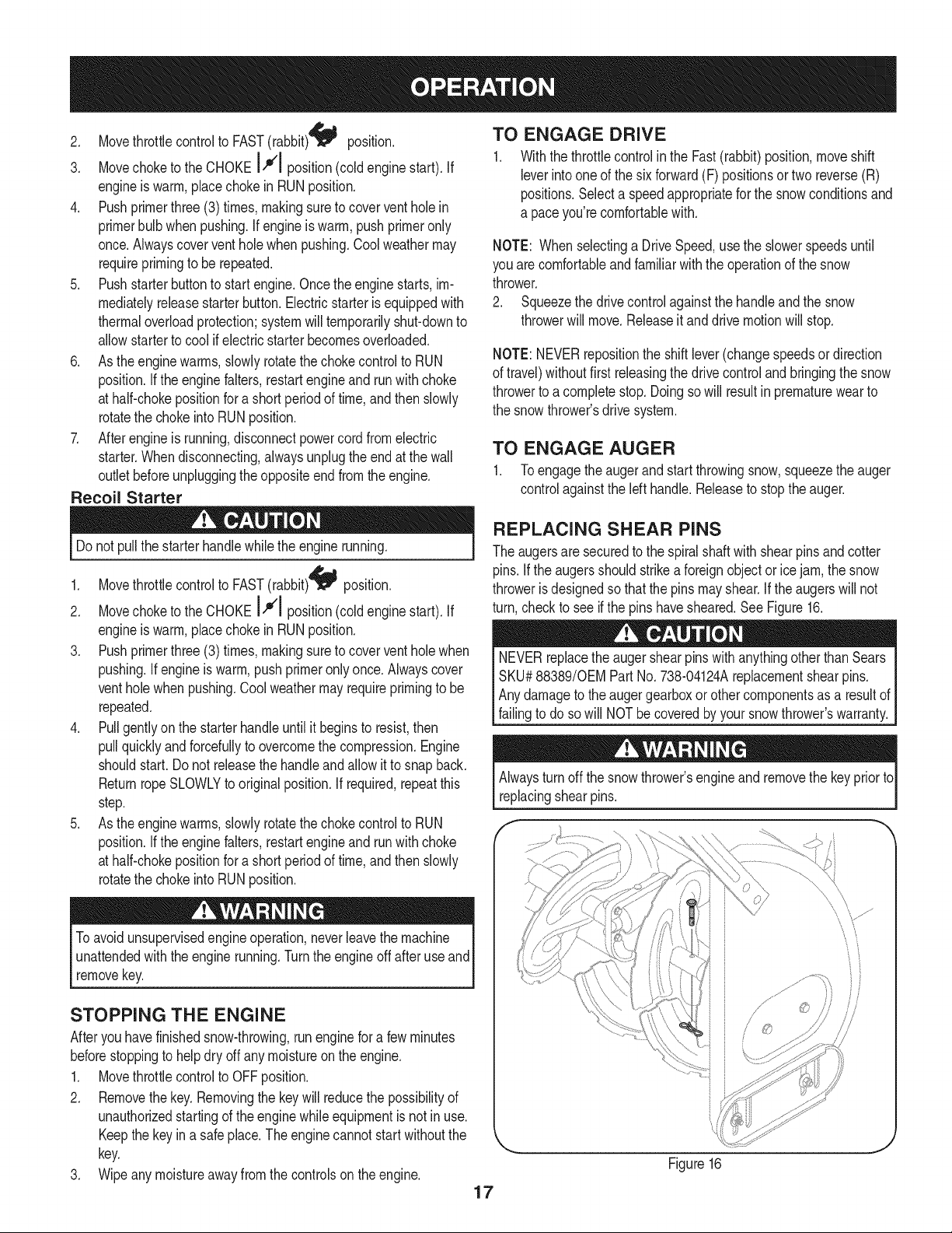
REPLACING SHEAR PiNS
The augersare securedto the spiralshaftwith shearpins and cotter
pins.If the augersshouldstrikea foreignobject or ice jam, the snow
throweris designedso thatthe pins mayshear.If theaugerswill not
turn,checkto see if the pins havesheared.SeeFigure16.
NEVERreplacethe augershearpinswithanythingotherthan Sears
SKU#88389/0EM PartNo. 738-04124Areplacementshearpins.
Anydamageto theaugergearboxorother componentsas a resultof
failingto do sowill NOTbecoveredbyyour snowthrower'swarranty.
Alwaysturn off thesnow thrower'sengineand removethe key priorto
replacingshearpins.
if -,
\
J
//
Figure16
MAINTENANCE SCHEDULE
Beforeperforminganytype ofmaintenance/service,disengageall
controlsand stoptheengine.Waituntilallmovingpartshavecometo
acompletestop.Disconnectsparkplugwireandgroundit againstthe
enginetopreventunintendedstarting.Alwayswearsafetyglassesduring
operationor whileperforminganyadjustmentsorrepairs.
EachUseandevery5
hours
1st5 hours
Annuallyor 25 hours
Annuallyor 50 hours
Annuallyor 100 hours
BeforeStorage
1. Engineoil level
2. Looseor missinghardware
3. Unit and engine.
1. Engineoil
1. Sparkplug
2. Controllinkagesand pivots
3. Wheels
4. Gear shaftand Augershaft
1. Engineoil
1. Sparkplug
1. Fuelsystem
Followthe maintenanceschedulegiven below.This chart describes
serviceguidelinesonly.Usethe ServiceLog columnto keeptrackof
completedmaintenancetasks.To locate the nearest Sears Service
Centeror to scheduleservice,simplycontactSearsat
1-800-4-MY-HOME®.
1. Check
2. Tightenor replace
3. Clean
1. Change
1. Check
2. Lubewith light oil
3. Lubewith multipurposeautogrease
4. Lubewith light oil
1. Change
1. Change
1. Runengineuntilit stopsfrom lack
d fuel
ENGINE MAINTENANCE
Checking Engine Oil
Beforelubricating,repairing,or inspecting,disengageall controls
Iandstopengine.Wait untilall movingpartshavecometo a complete
_stop.
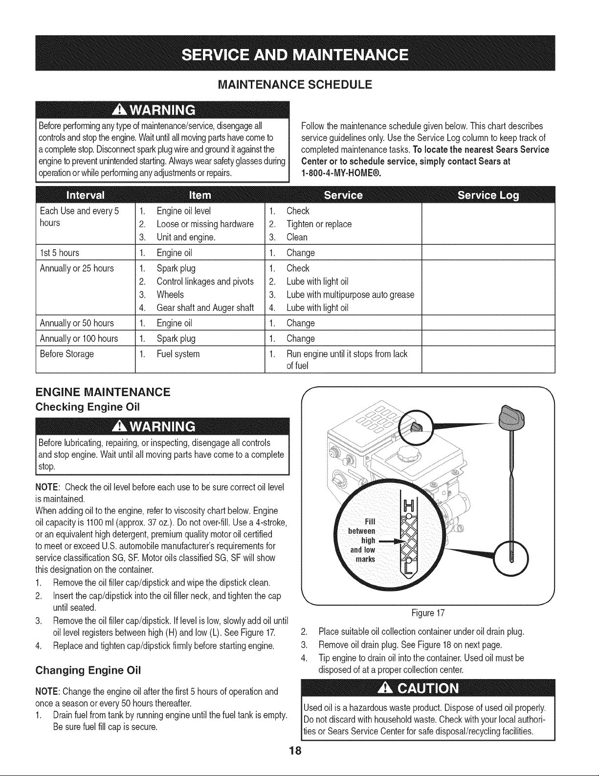
NOTE: Checktheoil levelbeforeeachuseto be surecorrectoil level
is maintained.
Whenaddingoilto the engine,referto viscositychart below.Engine
oilcapacityis 1100ml (approx.37oz.). Donot over-fill.Usea 4-stroke,
oran equivalenthighdetergent,premiumquality motoroil certified
to meetorexceedU.S.automobilemanufacturer'srequirementsfor
serviceclassificationSG, SR MotoroilsclassifiedSG, SFwill show
thisdesignationon the container.
1. Removethe oil fillercap/dipstickand wipethe dipstickclean.
2. Insertthe cap/dipstickintothe oil filler neck,and tightenthe cap
until seated.
3. Removethe oil fillercap/dipstick.If levelis low, slowlyadd oiluntil
oil levelregistersbetweenhigh (H) and low (L). SeeFigure17.
4. Replaceand tighten cap/dipstickfirmlybeforestartingengine.
Changing Engine Oil
NOTE:Changethe engineoilafterthe first5 hoursof operationand
oncea seasonor every 50 hoursthereafter.
1. Drainfuelfrom tank by runningengineuntilthe fuel tank is empty.
Besurefuel fill cap is secure.
J
Figure17
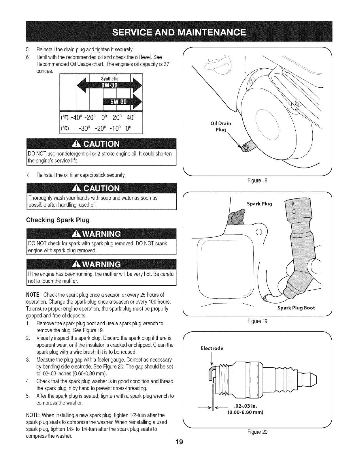
2. Placesuitableoil collectioncontainerunderoil drainplug.
3. Removeoil drain plug.See Figure18on nextpage.
4. Tip engineto drain oil intothe container.Usedoil mustbe
disposedof at a propercollectioncenter.
Usedoil is a hazardouswasteproduct.Disposeof usedoil properly.
IDo notdiscardwithhouseholdwaste.Checkwithyour localauthori-
lties or SearsServiceCenterfor safedisposal/recyclingfacilities.
18
.
6.
Reinstallthe drainplugandtightenit securely.
Refillwiththe recommendedoil andcheckthe oil level.See
RecommendedOil Usagechart.Theengine'soil capacityis 37
ounces.
i u
[
(%-40 °-20 o 0o 200 400
("c) -300 -200 -10° 0°
DO NOTuse nondetergentoilor 2-strokeengineoil. It could shorten
the engine'sservicelife.
Oil Drain
Plug
7. Reinstallthe oil fillercap/dipsticksecurely.
Figure18
Thoroughlywashyour handswithsoap andwateras soonas
possibleafterhandling usedoil.
Checking Spark Plug
DO NOTcheckfor sparkwithsparkplugremoved.DO NOTcrank
enginewith sparkplug removed.
Ifthe enginehas beenrunning,the mufflerwill bevery hot. Be careful
notto touchthe muffler.
NOTE: Checkthe sparkplugoncea seasonor every 25 hoursof
operation.Changethe sparkplug oncea seasonor every100hours.
Toensureproperengineoperation,the sparkplug mustbe properly
gappedandfreeof deposits.
1. Removethesparkplugbootand use a sparkplugwrenchto
removethe plug.See Figure19.
2. Visuallyinspectthe spark plug.Discardthe spark plug if thereis
apparentwear,orif the insulatoris crackedor chipped.Cleanthe
sparkplugwith a wirebrush if it is to be reused.
3. Measurethe plug gap with a feelergauge.Correctas necessary
by bendingsideelectrode.SeeFigure20. Thegap shouldbe set
to .02-.03inches(0.60-0.80ram).
4. Checkthatthe sparkplug washeris in good conditionandthread
the sparkplugin by handto preventcross-threading.
5. After thespark plug is seated,tightenwith a sparkplugwrenchto
compressthe washer.
NOTE:Wheninstallinga newsparkplug,tighten 1/2-turnafter the
sparkplugseatsto compressthe washer.Whenreinstallinga used
sparkplug,tighten1/8-to 1/4-turnafter the sparkplugseatsto
compressthe washer.
19
Spark Plug
O
J
Figure19
Electrode
.02-.03 in.
{0.60-0.80 ram)
Figure20
hotandcan ine.
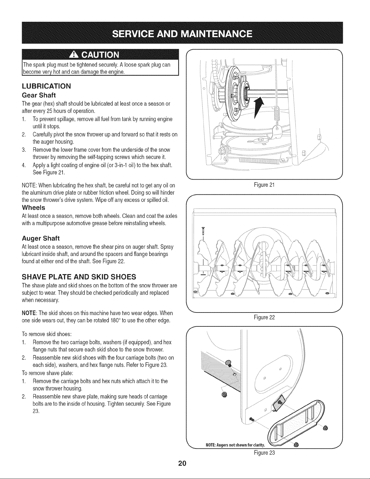
LUBRICATION
Gear Shaft
Thegear(hex)shaft shouldbe lubricatedat least oncea seasonor
afterevery25 hoursof operation.
1. Topreventspillage,removeall fuel fromtank by runningengine
until it stops.
2. Carefullypivotthe snowthrowerup and forwardso that it restson
theaugerhousing.
3. Removethe lowerframecoverfromthe undersideof the snow
throwerby removingthe self-tappingscrewswhichsecureit.
4. Applya lightcoatingof engineoil (or 3-in-1oil) to the hexshaft.
SeeFigure21.
NOTE:Whenlubricatingthe hexshaft,be carefulnotto get any oilon
thealuminumdriveplateor rubberfrictionwheel. Doingsowill hinder
the snowthrower'sdrive system.Wipeoff anyexcessor spilledoil.
Wheels
At leastoncea season,removebothwheels.Cleanand coat theaxles
witha multipurposeautomotivegreasebeforereinstallingwheels.
Auger Shaft
At leastoncea season,removethe shearpinson augershaft.Spray
lubricantinsideshaft,andaroundthe spacersand flangebearings
foundat eitherendof the shaft.SeeFigure22.
SHAVE PLATE AND SKID SHOES
The shaveplateand skid shoeson the bottomof the snowthrowerare
subjectto wear.Theyshouldbecheckedperiodicallyand replaced
whennecessary.
NOTE:Theskidshoeson this machinehavetwo wearedges.When
onesidewearsout,theycan be rotated1800to usethe otheredge.
To removeskidshoes:
1. Removethe twocarriagebolts,washers(if equipped),and hex
flangenutsthat secureeach skid shoeto the snowthrower.
2. Reassemblenew skid shoeswith the fourcarriagebolts (two on
eachside),washers,andhex flangenuts.Referto Figure23.
To removeshaveplate:
1. Removethe carriageboltsand hexnuts whichattachit to the
snowthrowerhousing.
2. Reassemblenew shaveplate,makingsureheadsof carriage
boltsareto the insideof housing.Tightensecurely.See Figure
23.
O i
)
J' "?X
/ .... )
{;:7,_"
7/'................
f
Figure21
J
Figure22
f
\
\
\
2O
NOTE:Augersnot shown for clarity.
Figure23
ADJUSTMENTS
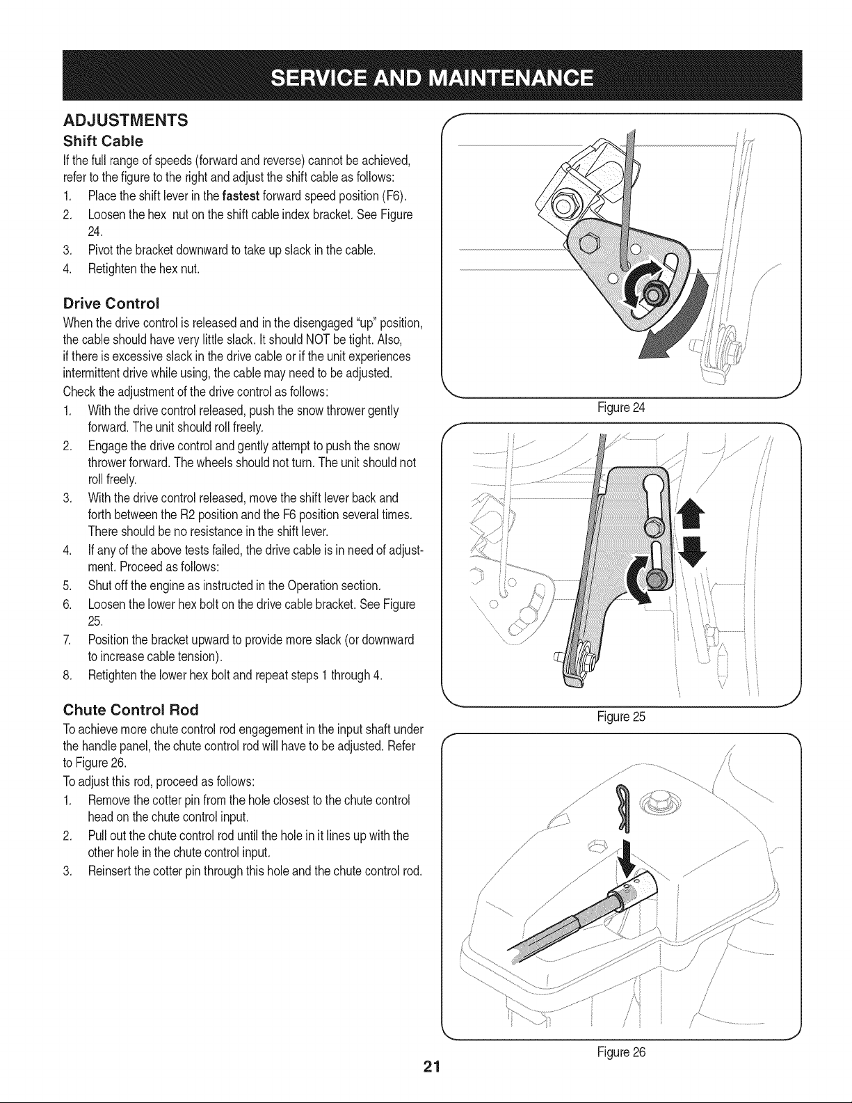
Shift Cable
If thefull rangeof speeds(forwardand reverse)cannotbe achieved,
referto the figureto the rightandadjustthe shift cableas follows:
1. Placethe shiftleverin thefastest forwardspeedposition(F6).
2. Loosenthe hex nuton the shiftcable indexbracket.SeeFigure
24.
3. Pivotthe bracketdownwardto take up slack in the cable.
4. Retightenthehex nut.
Drive Control
Whenthedrivecontrolis releasedandin thedisengaged"up"position,
the cableshouldhaveverylittle slack.It shouldNOTbetight. Also,
if thereis excessiveslackin thedrive cableor if the unitexperiences
intermittentdrivewhileusing,the cable mayneed to be adjusted.
Checktheadjustmentof the drivecontrolas follows:
1. Withthedrivecontrolreleased,pushthe snowthrowergently
forward.The unitshouldrollfreely.
2. Engagethe drivecontroland gently attemptto pushthe snow
throwerforward.Thewheelsshouldnotturn.The unitshouldnot
rollfreely.
3. With thedrivecontrol released,movethe shift leverbackand
forthbetweenthe R2positionand the F6 positionseveraltimes.
Thereshouldbeno resistancein the shiftlever.
4. If anyof the abovetestsfailed,the drivecable is in needof adjust-
ment.Proceedas follows:
5. Shutoff theengineas instructedin the Operationsection.
6. Loosenthe lowerhexbolt on the drivecable bracket.See Figure
25.
7. Positionthe bracketupwardto providemoreslack(or downward
to increasecabletension).
8. Retightenthe lowerhex boltand repeatsteps1 through4.
f
.........
J
Chute Control Rod
Toachievemorechutecontrolrodengagementin the input shaftunder
the handlepanel,the chutecontrolrod will haveto beadjusted.Refer
to Figure26.
Toadjustthis rod,proceedas follows:
1. Removethecotterpin fromthe hole closestto the chute control
headon thechute controlinput.
2. Pull outthe chute controlrod untilthe holein it lines upwiththe
otherholeinthe chutecontrolinput.
3. Reinsertthe cotterpin throughthis holeand thechute controlrod.
Figure25
J
/
/ ,
\
\
J
Figure26
21
Auger Control f "_
Referto the Assemblysectionfor instructionson adjustingtheauger
controlcable.
Skid Shoes
Referto the Assemblysectionfor instructionson adjustingthe skid
shoes.
BELT REPLACEMENT
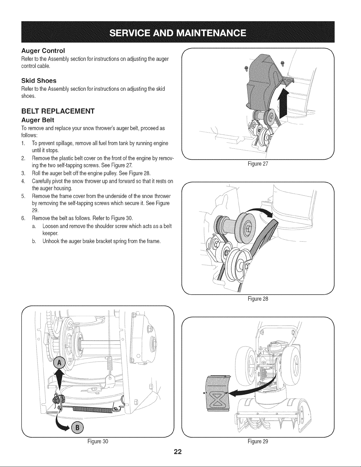
Auger Belt
To removeandreplaceyoursnowthrower'saugerbelt,proceedas
follows:
1. Topreventspillage,removeall fuel fromtank by runningengine
until itstops.
2. Removethe plasticbelt coveronthe front of the engineby remov-
ingthe twoself-tappingscrews.See Figure27.
3. Rollthe auger beltoff theenginepulley.See Figure28.
4. Carefullypivotthe snowthrowerup and forwardso that itrestson
theaugerhousing.
5. Removethe framecoverfrom the undersideof the snowthrower
by removingthe self-tappingscrewswhich secureit. See Figure
29.
6. Removethe beltas follows.Referto Figure30.
a. Loosenand removethe shoulderscrewwhich actsas a belt
keeper.
b. Unhookthe auger brakebracketspringfrom the frame.
i I
/
/
/
/
/
/
Figure27
J
f
Figure28
J
f
Figure30 Figure29
J
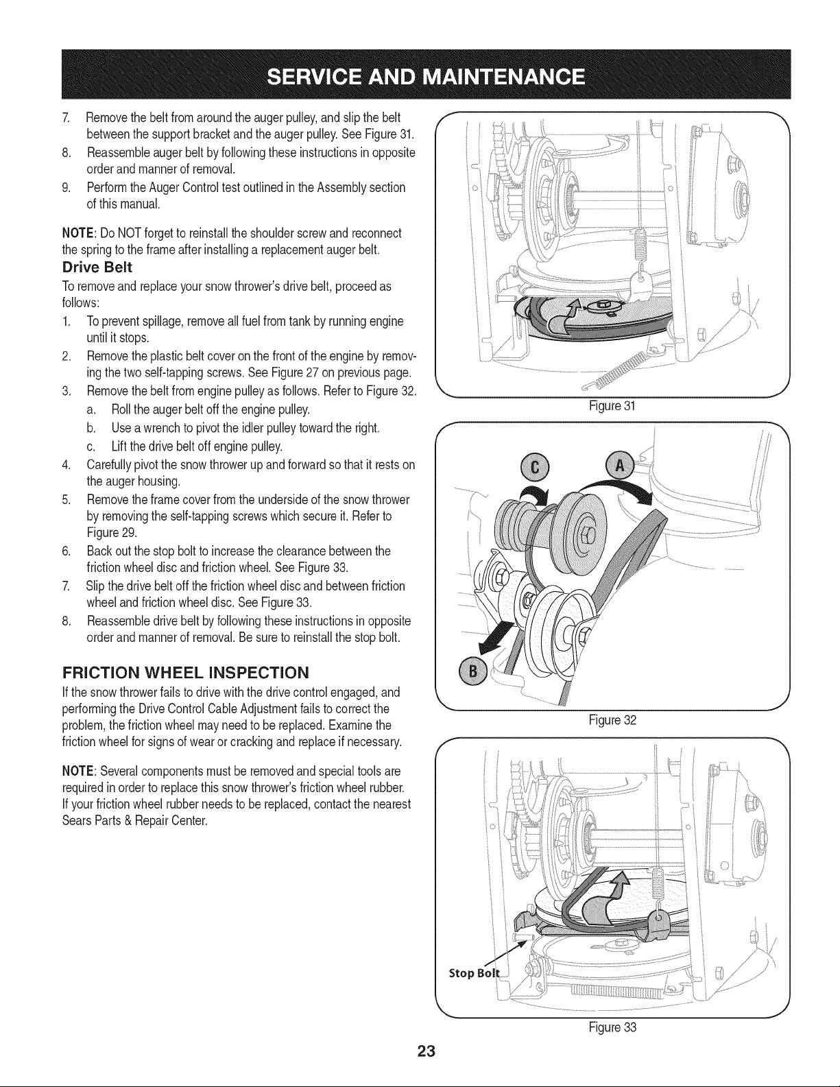
7. Removethebeltfromaroundtheaugerpulley,andslipthebelt
betweenthesupportbracketandtheaugerpulley.SeeFigure31.
8. Reassembleaugerbeltbyfollowingtheseinstructionsinopposite
orderandmannerofremoval.
9. PerformtheAugerControltestoutlinedintheAssemblysection
ofthismanual.
NOTE:DoNOTforgettoreinstalltheshoulderscrewandreconnect
thespringtotheframeafterinstallingareplacementaugerbelt.
Drive Belt
Toremoveand replaceyoursnow thrower'sdrivebelt,proceedas
follows:
1. Topreventspillage,removeallfuel fromtankby runningengine
untilit stops.
2. Removetheplasticbelt coveron the front of the engineby remov-
ingthe twoself-tappingscrews.See Figure27on previouspage.
3. Removethebelt from enginepulleyas follows. Referto Figure32.
a. Rollthe auger beltoff theenginepulley.
b. Use a wrenchto pivotthe idlerpulleytowardthe right.
c. Liftthe drivebelt off enginepulley.
4. Carefullypivotthe snowthrowerup and forwardsothat itrestson
the augerhousing.
5. Removetheframe coverfrom the undersideof the snowthrower
by removingthe self-tappingscrewswhich secureit. Referto
Figure29.
6. Back outthe stop bolt to increasethe clearancebetweenthe
frictionwheeldiscandfrictionwheel.SeeFigure33.
7. Slipthe drivebelt offthe frictionwheeldiscandbetweenfriction
wheelandfrictionwheeldisc.SeeFigure33.
8. Reassembledrive beltby followingthese instructionsinopposite
orderand mannerof removal.Be sureto reinstallthe stop bolt.
FRICTION WHEEL INSPECTION
If the snowthrowerfails to drivewith thedrivecontrolengaged,and
performingthe DriveControlCableAdjustmentfailsto correctthe
problem,the frictionwheelmayneedto be replaced.Examinethe
frictionwheelfor signsof wearor crackingandreplaceif necessary.
NOTE:Severalcomponentsmustbe removedand specialtools are
requiredinorder to replacethis snowthrower'sfrictionwheelrubber.
If yourfrictionwheel rubberneedsto be replaced,contact the nearest
SearsParts& RepairCenter.
f
iO i
Stop Bol
Figure31
Figure32
Figure33
J
23
Ifthe snowthrowerwillnot be usedfor30 daysor longer,or if it is the endof the snowseasonwhenthe last possibilityof snowis gone,the
equipmentneedsto bestoredproperly.Followstorageinstructionsbelowto ensuretop performancefromthe snowthrowerfor manymoreyears.
PREPARING ENGINE
Enginesstoredover30days need to be drainedof fuel to prevent
deteriorationandgumfromforminginfuel systemor on essential
carburetorparts.If thegasolinein yourenginedeterioratesduring
storage,youmayneedto havethe carburetor,andotherfuel system
components,servicedor replaced.
1. Removeall fuel fromtank by runningengineuntil it stops.Donot
attemptto pourfuel fromthe engine.
2. Changethe engineoil.
3. Removesparkplug and pour approximately1oz.(30 rnl)of clean
engineoil intothe cylinder.Pullthe recoilstarterseveraltimesto
distributetheoil, and reinstallthe spark plug.
4. Cleandebrisfrom aroundengine,and under,around,andbehind
muffler.Applya lightfilmof oilon anyareasthatare susceptible
to rust.
• Storeina clean,dry andwellventilatedarea awayfrom anyap-
pliancethatoperateswith a flame or pilotlight,suchas a furnace,
waterheater,or clothesdryer.Avoidany areawith a spark
producingelectricmotor,or wherepowertoolsare operated.
Neverstoresnowthrowerwith fuel intank indoorsor in poorlyventi-
latedareas,wherefuel fumesmayreachan openflame,spark or pilol
lightas ona furnace,water heater,clothesdryer or gas appliance.
• If possible,avoidstorageareaswith high humidity.
• Keepthe enginelevelin storage.Tiltingcan causefuel or oil
leakage.
PREPARING SNOW THROWER
Whenstoringthe snowthrowerin an unventilatedormetal stor-
age shed,careshouldbe taken to rustprooftheequipment.Using
a light oil or silicone,coattheequipment,especiallyanychains,
springs,bearingsandcables.
• Removealldirt fromexteriorof engineand equipment.
• Followlubricationrecommendations.
• Storeequipmentin a clean,dry area.
24
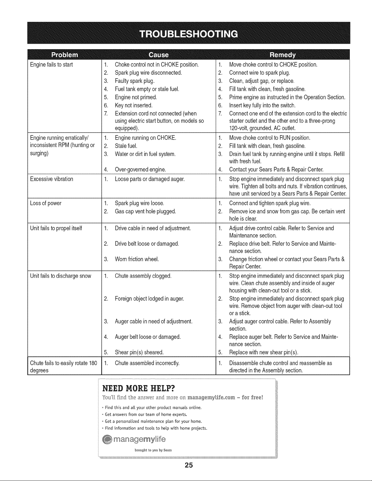
Enginefailsto start
Enginerunningerratically/
inconsistentRPM(huntingor
surging)
Excessivevibration
Lossof power
Unitfailsto propelitself
Unitfailsto dischargesnow
1. Chokecontrolnot in CHOKEposition.
2. Sparkplugwire disconnected.
3. Faultysparkplug.
4. Fueltank emptyor stalefuel.
5. Enginenot primed.
6. Keynot inserted.
7. Extensioncordnot connected(when
usingelectricstartbutton,on modelsso
equipped).
1. Enginerunningon CHOKE.
2. Stalefuel.
3. Wateror dirt in fuel system.
4. Over-governedengine.
1. Loosepartsor damagedauger.
1. Sparkplugwire loose.
2. Gascap vent hole plugged.
1. Drivecable in need of adjustment.
2. Drivebelt looseor damaged.
3. Wornfrictionwheel.
1. Chuteassemblyclogged.
2. Foreignobject lodgedin auger.
3. Augercablein needof adjustment.
4. Augerbelt looseordamaged.
5. Shearpin(s) sheared.
1. Chuteassembledincorrectly.
1. Movechokecontrolto CHOKEposition.
2. Connectwireto sparkplug.
3. Clean,adjustgap,or replace.
4. Filltank with clean,freshgasoline.
5. Primeengineas instructedin the OperationSection.
6. Insertkeyfully intothe switch.
7. Connectone end of the extensioncordto the electric
starteroutletandthe otherendto a three-prong
120-volt,grounded,ACoutlet.
1. Movechokecontrolto RUNposition.
2. Filltank with clean,freshgasoline.
3. Drainfueltank by runningengineuntil it stops. Refill
withfreshfuel.
4. ContactyourSearsParts & RepairCenter.
1. Stopengineimmediatelyand disconnectsparkplug
wire.Tightenall boltsand nuts.Ifvibrationcontinues,
haveunit servicedbya SearsParts& RepairCenter.
1. Connectand tightensparkplugwire.
2. Removeiceand snowfromgascap. Becertainvent
holeis clear.
1. Adjustdrivecontrolcable. Referto Serviceand
Maintenancesection.
2. Replacedrive belt. Referto Serviceand Mainte-
nancesection.
3. Changefrictionwheelor contactyour SearsParts&
RepairCenter.
1. Stopengineimmediatelyand disconnectsparkplug
wire.Cleanchuteassemblyandinsideof auger
housingwithclean-outtoolor a stick.
2. Stopengineimmediatelyand disconnectsparkplug
wire.Removeobjectfrom augerwith clean-outtool
ora stick.
3. Adjustaugercontrolcable. Referto Assembly
section.
4. Replaceauger belt. Referto Serviceand Mainte-
nancesection.
5. Replacewith newshearpin(s).
Chutefailsto easilyrotate 180 1. Disassemblechutecontroland reassembleas
degrees directedinthe Assemblysection.
NEED HORE HELP?
Yot,Fttfind. th_ answer a!ld mo_e on ma_age_y_ifeocom _ for free]
Find this and att your other product manua[s ontine.
Get answers from our team of home experts.
Get a personalized maintenance p[an for your home.
Find information and tools to he[p with home projects.
managemylife
b_e'_g_t_/_eyeu by Sea_s
25
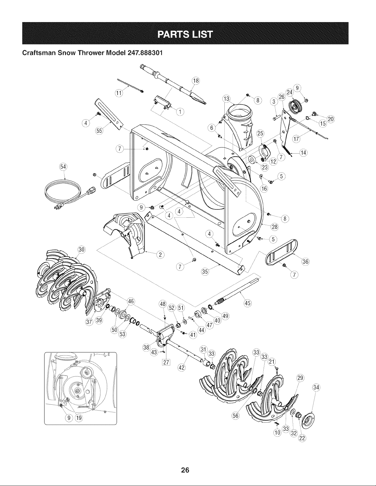
Craftsman Snow Thrower IViodel 247.888301
i27j
/
/
@
/
!
/
26
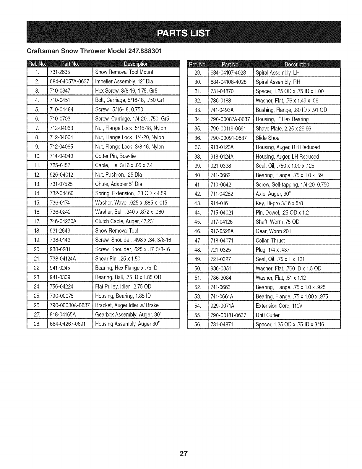
Craftsman Snow Thrower IViodel 247.888301
D = 0 0
731-2635 SnowRemovalToolMount
2. 684-04057A-0637 ImpellerAssembly,12"Dia.
3. L710-0347 LHexScrew,3/8-16, 1.75,Gr5
4. 710-0451 Bolt,Carriage,5/16-18,.750Grl
5. 710-04484 Screw, 5/16-18,0.750
6. 710-0703 Screw,Carriage,1/4-20,.750,Gr5
7. 712-04063 Nut, FlangeLock,5/16-18,Nylon
8. 712-04064 Nut, FlangeLock,1/4-20,Nylon
9. 712-04065 Nut, FlangeLock,3/8-16,Nylon
10. 714-04040 CotterPin,Bow-tie
11. J 725-0157 l Cable,Tie, 3/16x .05x 7.4
12. 926-04012 Nut, Push-on,.25 Dia
13. 731-07525 Chute,Adapter5" Dia
14. 732-04460 Spring,Extension,.38OD x 4.59
15. 736-0174 Washer,Wave,.625x .885x .015
16. 736-0242 Washer,Bell, .340x .872x .060
17. 746-04230A ClutchCable,Auger,47.23"
18. 931-2643 SnowRemovalTool
19. .738-0143 _ Screw,Shoulder,.498x .34,3/8-16
20. 938-0281 Screw,Shoulder,.625x .17,3/8-16
21. 738-04124A ShearPin, .25x 1.50
22. 941-0245 Bearing,Hex Flangex .75ID
23. 941-0309 Bearing,Ball,.75 ID x 1.85OD
24. 756-04224 FlatPulley,Idler, 2.75OD
25. 790-00075 Housing,Bearing,1.85ID
26. 790-00080A-0637 Bracket,AugerIdlerw/Brake
27. J 918-04165A J GearboxAssembly,Auger,30"
28. 684-04267-0691 HousingAssembly,Auger30"
684-04107-4028
30. 684-04108-4028
31. 731-04870
32. 736-0188
33. 741-0493A
34. 790-00087A-0637
35. 790-00119-0691
36. 790-00091-0637
37. 918-0123A
38. 918-0124A
39. 921-0338
40. 741-0662
41. 710-0642
42. 711-04282
D = O O
SpiralAssembly,LH
SpiralAssembly,RH
Spacer,1.25OD x .75IDx 1.00
Washer,Flat,.76x 1.49x .06
Bushing,Flange,.80ID x .91OD
Housing,1"HexBearing
ShavePlate,2.25 x 29.66
SlideShoe
Housing,Auger,RH Reduced
Housing,Auger,LH Reduced
Seal,Oil, .750x 1.00x .125
Bearing,Flange,.75x 1.0x .59
Screw,Self-tapping,1/4-20,0.750
Axle,Auger,30"
43. 914-0161 Key,Hi-pro3/16x 5/8
44. 715-04021 Pin, Dowel,.25 ODx 1.2
45. 917-04126 Shaft,Worm.75OD
46. 917-0528A Gear,Worm20T
47. 718-04071 Collar,Thrust
48. 721-0325 Plug, 1/4x .437
49. 721-0327 Seal,Oil, .75x 1x .131
50. 936-0351 Washer,Flat,.760IDx 1.50D
51. 736-3084 Washer,Flat,.51x 1.12
52. 741-0663 Bearing,Flange,.75x 1.0x .925
53. 741-0661A Bearing,Flange,.75x 1.00x .975
54. 929-0071A ExtensionCord,110V
55. 790-00181-0637 Drift Cutter
56. 731-04871 Spacer,1.25OD x .75IDx 3/16
27
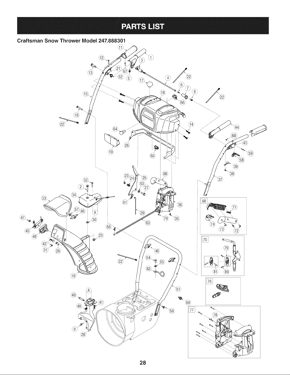
Craftsman Snow Thrower Model 247.888301
€
,,65/,
28
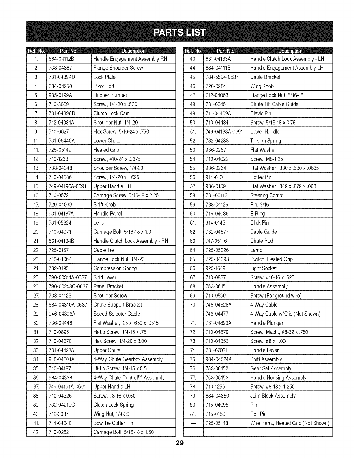
D _ W
684-04112B HandleEngagementAssemblyRH
2. 738-04367 FlangeShoulderScrew
3. 731-04894D LockPlate
4. 684-04250 PivotRod
5. 935-0199A RubberBumper
6. 710-3069 Screw,1/4-20x .500
7. 731-04896B ClutchLockCam
8. 712-04081A ShoulderNut, 1/4-20
9. 710-0627 HexScrew,5/16-24x .750
10. 731-06440A LowerChute
11. 725-05149 HeatedGrip
12. 710-1233 Screw,#10-24x 0.375
13. 738-04348 ShoulderScrew,1/4-20
14. 710-04586 Screw,1/4-20x 1.625
15. 749-04190A-0691 UpperHandleRH
16. 710-0572 CarriageScrew,5/16-18x 2.25
17. 720-04039 Shift Knob
18. 931-04187A HandlePanel
19. 731-05324 Lens
20. 710-04071 CarriageBolt,5/16-18x 1.0
21. 631-04134B HandleClutchLockAssembly- RH
22. 725-0157 CableTie
23. 712-04064 FlangeLockNut, 1/4-20
24. 732-0193 CompressionSpring
25. 790-00311A-0637 ShiftLever
26. 790-00248C-0637 PanelBracket
27. 738-04125 ShoulderScrew
28. 684-04310A-0637 ChuteSupportBracket
29. 946-04396A SpeedSelectorCable
30. 736-04446 FiatWasher,.25x .630x .0515
31. 710-0895 Hi-LoScrew,1/4-15x .75
32. 710-04370 HexScrew,1/4-20x 3.00
33. 731-04427A UpperChute
34. 918-04801A 4-WayChuteGearboxAssembly
35. 710-04187 Hi-LoScrew,1/4-15x 0.5
36. 984-04338 4-WayChuteControlTM Assembly
37. 749-04191A-0691 UpperHandleLH
38. 710-04326 Screw,#8-16x 0.50
39. 732-04219C ClutchLockSpring
40. 712-3087 Wing Nut,1/4-20
41. 714-04040 BowTieCotter Pin
42. 710-0262 CarriageBolt,5/16-18x 1.50
29
D _ O O
631-04133A HandleClutchLockAssembly- LH
44. 684-04111B HandleEngagementAssemblyLH
45. 784-5594-0637 Cable Bracket
46. 720-0284 Wing Knob
47. 712-04063 FlangeLock Nut,5/16-18
48. 731-06451 ChuteTilt CableGuide
49. 711-04469A ClevisPin
50. 710-04484 Screw,5/16-18x 0.75
51. 749-04138A-0691 LowerHandle
52. 732-04238 TorsionSpring
53. 936-0267 FiatWasher
54. 710-04022 Screw,M8-1.25
55. 936-0264 FiatWasher,.330x .630x .0635
56. 914-0101 Cotter Pin
57. 936-0159 FiatWasher,.349x .879x .063
58. 731-06113 SteeringControl
59. 738-04126 Pin,3/16
60. 716-04036 E-Ring
61. 914-0145 Click Pin
62. 732-04677 CableGuide
63. 747-05116 ChuteRod
64. 725-05326 Lamp
65. 725-04393 Switch,HeatedGrip
66. 925-1649 LightSocket
67. 710-0837 Screw,#10-16x .625
68. 753-06151 HandleAssembly
69. 710-0599 Screw (Forgroundwire)
70. 746-04528A 4-WayCable
746-04477 4-WayCablew/Clip (Not Shown)
71. 731-04893A HandlePlunger
72. 710-04879 Screw,Mach.,#8-32x .750
73. 710-04353 Screw,#8 x 1.00
74. 731-07031 HandleLever
75. 984-04324A ShiftAssembly
76. 753-06152 GearSet Assembly
77. 753-06153 HandleHousingAssembly
78. 710-1256 Screw,#8-18x 1.250
79. 684-04350 Joint BlockAssembly
80. 715-04095 Pin
81. 715-0150 RollPin
-- 725-05148 Wire Harn.,HeatedGrip (Not Shown)
__ 4_ ._
Craftsman Snow Thrower IViodel 247.888301 _.._,=_. _ -'-_,
/49__" _ _53)
¢_
_ (761
(t
3O
)
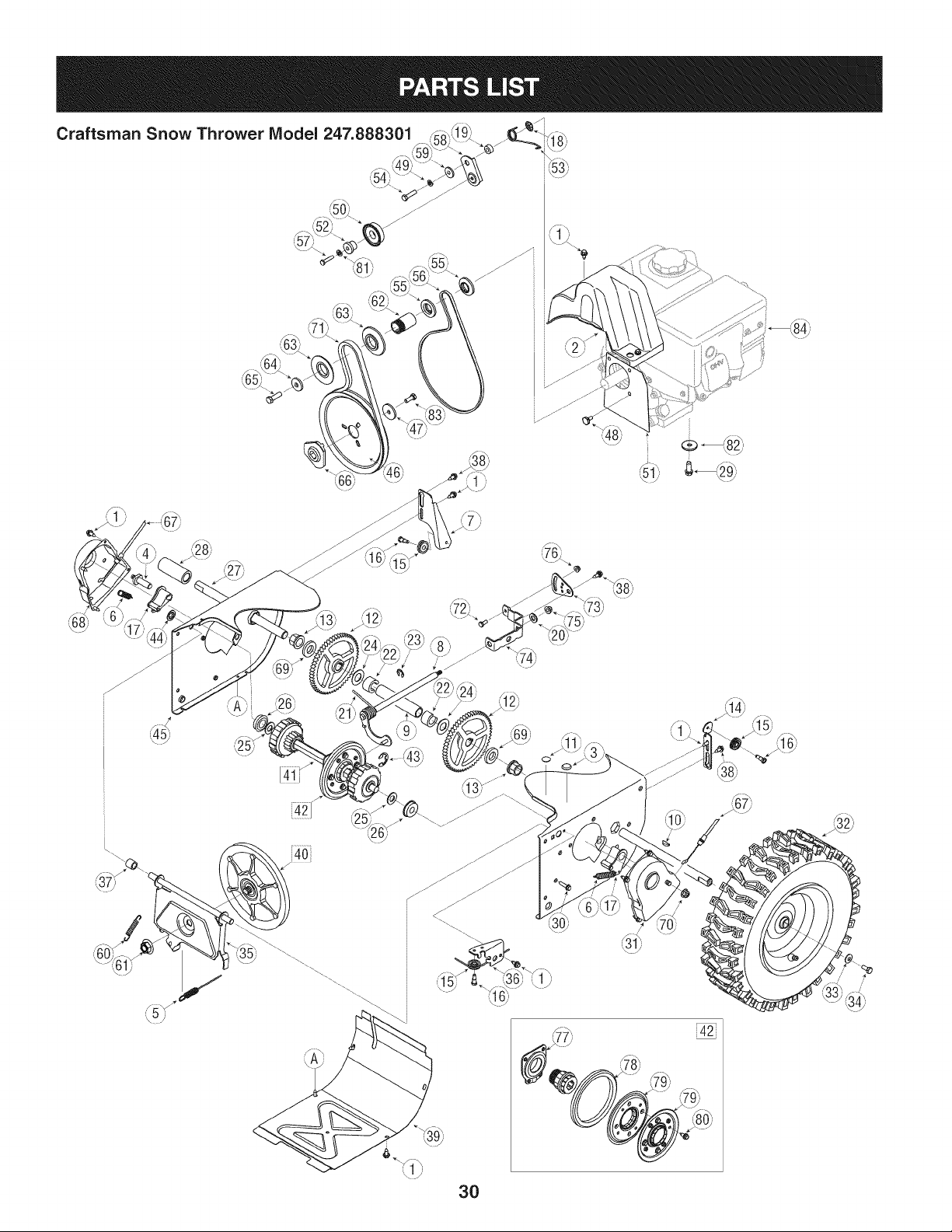
D_i BO¸
710-1652 AB Screw,1/4-20x 0.625
2. 731-06401 BeltCover
3. 735-04099 Plug,3/8 ID
4. 711-1268B ActuatorShaft
5. 746-04229B DriveClutchCable
6. 732-04345 ExtensionSpring
7. 790-00207B DriveClutchCableGuideBracket
8. 684-04156A ShiftRodAssembly
9. 750-04474 AxleSupportTube
10. 914-0126 Hi ProKey
11. 735-04100 Plug,1/2 ID
12. 917-04210 Gear,56T
13. 941-0245 Hex FlangeBearing
14. 790-00206A-0637 AugerClutchCableGuideBracket
15. 756-0625 CableRoller
16. 738-0924A C Screw,1/4-28x 0.375
17. 618-04288 DoggAssembly- LH
618-04287 DoggAssembly- RH
18. 926-04012 Push-onNut
19. 750-04477A Spacer
20. 936-3015 Washer,Fiat
21. 732-04311A TorsionSpring,.7501Dx .968 Lg.
22. 731-05297 Spacer
23. 916-0104 E Ring
24. 736-0188 FiatWasher,.76x 1.49x .06
25. 736-0626 FiatWasher
26. 741-04076 BallBearing
27. 938-04180 Axle
28. L731-04873 Spacer
29. 710-0654A
30. 710-0788
31. 790-00185-0691
32. 634-04136-0911
634-04137-0911
TTSeresScrew,3/8-16x 1.0
TTScrew,1/4-20x 1.0
ShaftRetainer- LH
WheelComplete-LH
WheelComplete-RH
33. 736-0242
34. 710-0627
35. 684-04154B-0637
36. 790-00096-0637
3_ 748-0190
38. 738-04184A
39. 790-00316-0637
40. 656-04055
41. 918-04322A
BellWasher
HexBolt,5/16-24x 0.75
FrictionWheelSupportBrkt.Assy.
AugerCableGuideBracket
Spacer
ShoulderScrew
FrameCover
FrictionWheelDiscAssembly
DriveShaftAssembly
31
m _ O
684-04159 FrictionWheelAssembly
43. 716-0136 RetainerRing
44. 726-0221 SpeedNut
45. 790-00183B-0637 WheelDriveFrame
46. 756-04109 AugerPulley
47. 736-0505 FiatWasher
48. 738-04439 ShoulderScrew
49. 936-0119 LockWasher
50. 684-04169 IdlerPulleyAssembly
51. 790-00332-0637 Pit.,Cvr.
52. 750-04571 Spacer
53. 732-04308B TorsionSpring
54. 710-0672 HexScrew,5/16-24x 1.25
55. 756-04252 PulleyHalf
56. 954-04201A Belt,WheelDrive
57. 710-0809 TT Screw,1/4-20x 1.25
58. 790-00208C DriveClutchIdlerBracket
59. 748-04112B ShoulderSpacer
60. 932-0264 ExtensionSpring
61. 712-0417A FlangeNut,5/8-18
62. 750-04303 Spacer
63. 756-04113 PulleyHalf
64. 736-0247 FiatWasher
65. 710-0191 HexBolt,3/8-24x 1.25
66. 748-04053A PulleyAdapter
67. 946-0956B SteeringCable
68. 790-00186-0691 ShaftRetainer- RH
69. 750-0767 Axle Spacer
70. 712-04065 FlangeLockNut,3/8-16
71. 954-04195 V-Belt,.500x 37.00Lg
72. 710-0751 HexScrew,1/4-20x .620
73. 790-00217A-0637 SpeedSelectorPivotBracket
74. 790-00218A-0637 SpeedSelectorShiftBracket
75. 712-04063 FlangeLockNut,5/16-18
76. 712-04064 FlangeLockNut, 1/4-20
77. 618-0063A FrictionWheelBearingAssembly
78. 935-04054 FrictionWheel
79. 790-00174 FrictionPlate
80. 710-0599 Screw,1/4-20x .500
81. 936-0329 LockWasher
82. 736-0320 Washer,Fiat,.38x 1.38x .125
83. 710-1245B HexBolt,5/16-24x 0.875
84. 752Z483-SUA ReplacementEngine
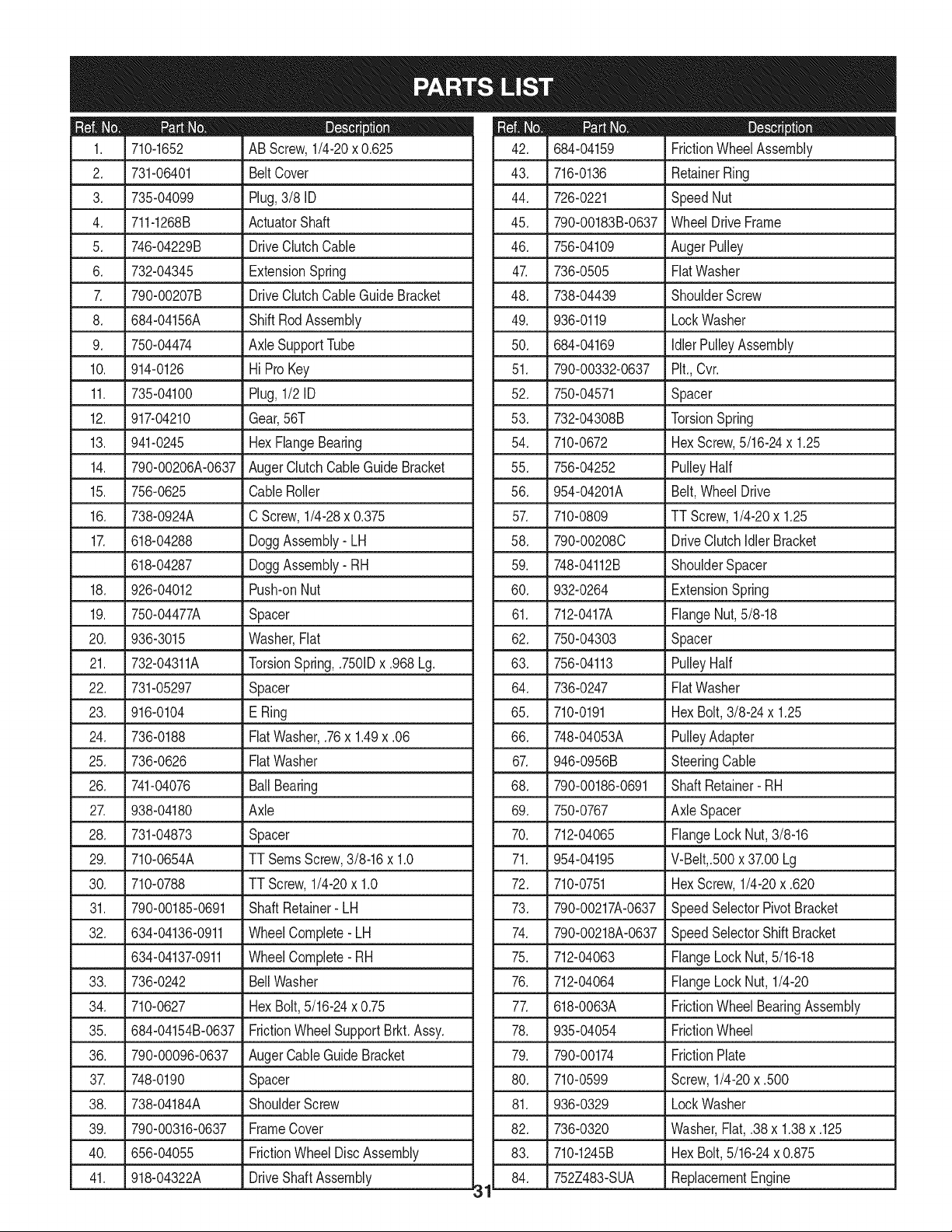
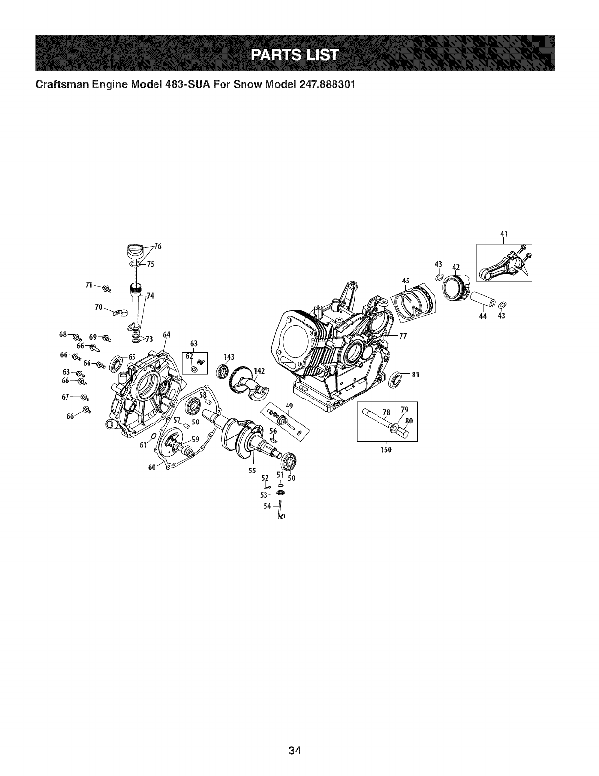
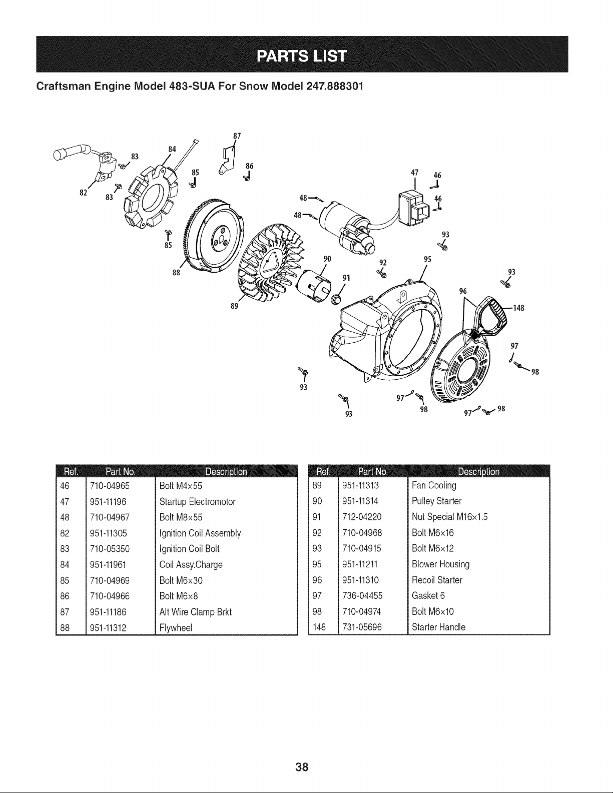
Craftsman Engine Model 483=SUA For Snow Model 247.888301
7
m
1
2
3
4
5
6
7
9
10
11
12
13
14
15
710-04968
951-11339
710-04915
951-10757
951-11595
951-10637
731-05632
951-11302
710-04914
951-11181
951-11321
710-04968
951-11338
712-04219
D = O
Bolt,M6x14
MufflerShield
Bolt M6x12
ThrottleControlKnob
ControlPanel
KeySwitch Base
Key
ChokeKnob
Bolt M6xlO
ExhaustPipeShield
CarbIsolatorBracket
Bolt M6x16
MufflerAssembly
NutM8
32
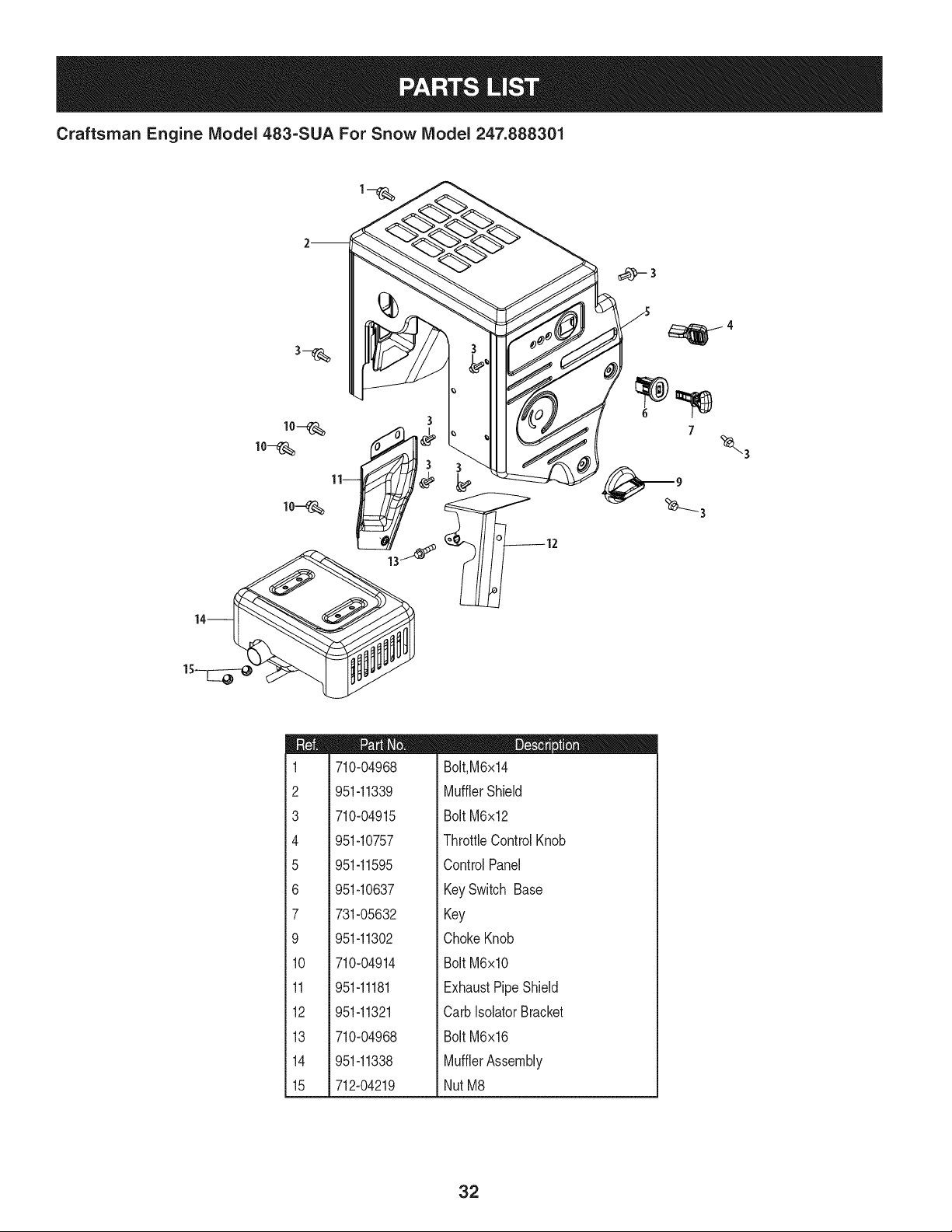
Craftsman Engine IViodel 483-SUA For Snow IViodel 247.888301
rs
c _jj-u
w
_131
,39-
140-0 0114O
141/
m
129
130
131
132
133
134
135
136
138
139
140
141
a
b
¢
d
e
f
g
h
710-05392
710-05056
951-11315
951-11316
951-11223
951-11303A
951-10639A
951-11824
951-11304
951-11192
736-04477
712-04212
n/a
n/a
n/a
n/a
n/a
n/a
n/a
n/a
D = e
StudM6-8x100 Carburetor
StudM6-8x118 Carburetor
CarburetorInsulatorGasket
CarburetorInsulator
CarburetorGasket
CarburetorAssembly
PrimerAssembly
Primer
HeaterBox
ChokeControl
LockWasher
NutM6
ChokeShaft
LockWasher
ScrewM3x5
ChokePlate
ThrottleShaft
ThrottlePlate
LockPlate
IdleJetAssembly
m
I
J
k
I
m
n
0
P
q
r
s
t
U
V
W
X
Y
n/a
n/a
751-11991
951-11906
n/a
n/a
n/a
n/a
n/a
n/a
n/a
951-11970
n/a
951-11348
710-04945
951-11349
710-04938
951-11332A
D = O 0
IdleSpeedAdjustingScrew
MixtureScrew
PrimerHose
HoseClamp
CarburetorBody
FloatPin
EmulsionTube
NeedleValve
MainJet
NeedleValveSpring
Float
FuelBowlGasket
FuelBowl
FuelBowlGasket
FuelBowlMountingBolt
FuelDrainPlugGasket
FuelDrainPlug
CarburetorKit- Major
(Incl.g,h,n,o,p,q,r,w,t,v,x)
33
Craftsman Engine IViodel 483=SUA For Snow IViodel 247.888301
142
41
I
44 43
34
Craftsman Engine IViodel 483=SUA For Snow IViodel 247.888301
m
41
42
43
44
45
49
5O
51
52
53
54
55
56
57
58
59
60
61
62
63
64
65
66
67
68
951-11951
951-11952
951-11953
951-11954
951-12579
951-11956
951-11373
736-04453
714-04077
951-11958
951-11365
951-11342
951-10307
715-04102
715-04092
951-11959
951-11376
736-04476
951-11960
951-11345
951-11340
951-11375
710-04971
710-04972
710-05052
m = O Q
ConnectingRodAssembly
Piston
PistonPinSnap Ring
PistonPin
PistonRingSet
GovernorGear/ShaftAssembly
RadialBallBearing6202-P6
Washer8x20x0.8
CotterPin
GovernorSeal
GovernorArm Shaft
CrankshaftKit
(Incl.50,55,56,65,81)
WoodruffKey
DowelPin9x12
DowelPin7x14
CamshaftAssy.
CrankcaseCoverGasket
Washer16x24x0.5
O-Ring16x3
Oil FillerPlugAssembly
CrankcaseCoverKit
(Incl.50,60,61,64-68)
Oil Seal30x46x8
Bolt M8x38
Bolt M8x45
Bolt M8x35
m
69
7O
71
73
74
75
76
77
78
79
8O
81
142
143
150
710-04968
951-11320
710-05349
951-11381
951-11972
951-11904
951-11971A
951-11341A
951-11350
736-04440
710-04906
951-11499
951-11968
951-11969
951-10641
952Z483-SUA
951-11331
951-11330A
951-11328B
m = W O
Bolt M6x16
DipstickClamp
Bolt M6x8
Oil FillTubeO-Ring
Oil FillTubeAssembly
DipstickO-Ring
DipstickAssembly
CrankcaseKit
(In01.50,53,77,81)
Oil DrainPipe Assy.
Washer10x16x1.5
Oil DrainPlug
OilSeal35x52x7
BalanceableShaftAssy.
Bearing6207-P6
Oil DrainAssembly
CompleteEngine
GasketKit- External
(Incl.79,108,125,131-133)
GasketKit- Complete
(Incl.53,60,65,79,81,106,
108,125,131-133)
ShortBlockAssembly
(Incl.41-45,49-61,63-68,77-79,
81,102,105,106,108,110,125,
131,132,142,143)
35
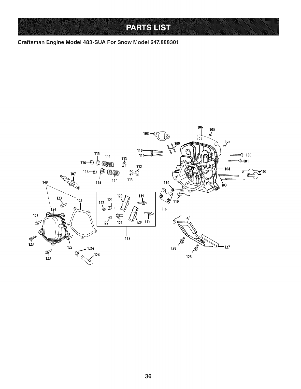
Craftsman Engine Model 483-SUA For Snow Model 247.888301
149
107
125
115
114
115
113
123
123
110_
11_
112
113
122 121 120 119
I
118
_126a
(_ ,126
_I04
103
36
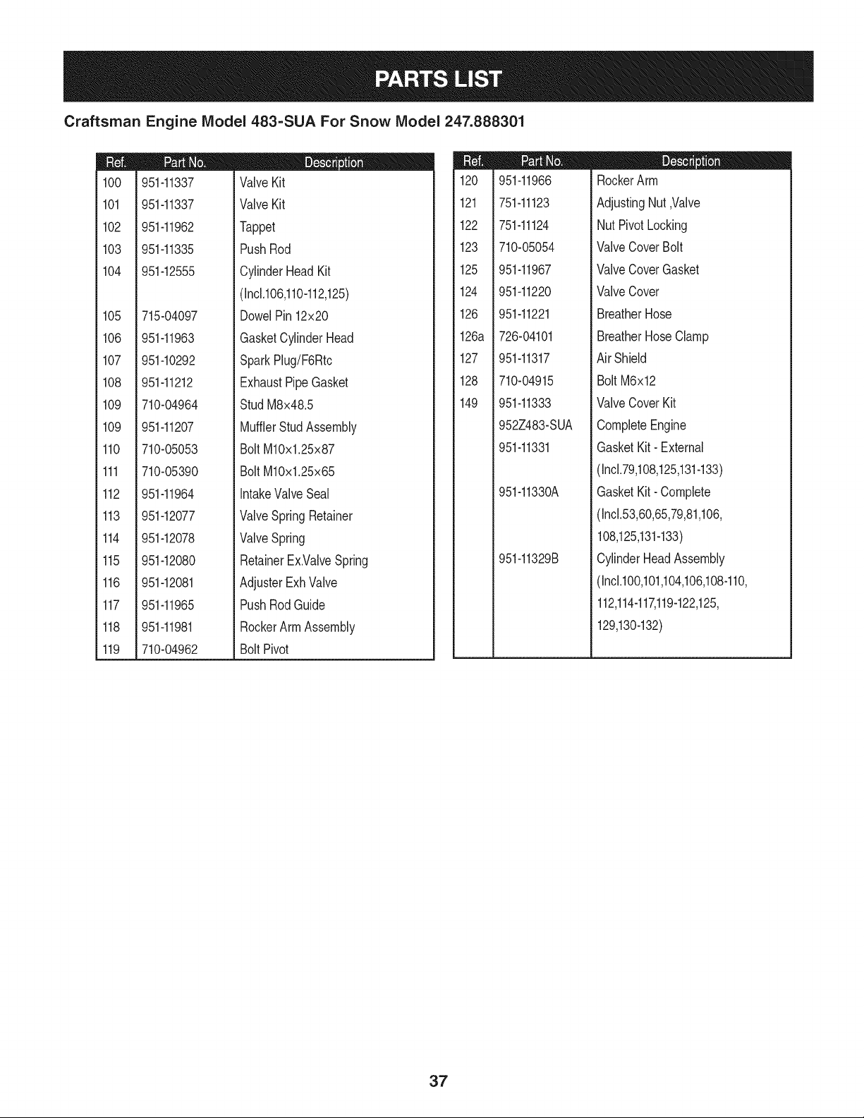
Craftsman Engine IViodel 483=SUA For Snow IViodel 247.888301
m
1CO
101
102
103
104
105
106
107
108
109
109
110
111
112
113
114
115
116
117
118
119
951-11337
951-11337
951-11962
951-11335
951-12555
715-04097
951-11963
951-10292
951-11212
710-04964
951-11207
710-05053
710-05390
951-11964
951-12077
951-12078
951-12080
951-12081
951-11965
951-11981
710-04962
D = O
ValveKit
ValveKit
Tappet
PushRod
CylinderHeadKit
(Inc1.106,110-112,125)
DowelPin12x20
GasketCylinderHead
SparkPlug/F6Rtc
ExhaustPipeGasket
StudM8x48.5
MufflerStudAssembly
BoltM10x1.25x87
BoltM10x1.25x65
IntakeValveSeal
ValveSpringRetainer
ValveSpring
RetainerEx.ValveSpring
AdjusterExhValve
PushRodGuide
RockerArmAssembly
BoltPivot
m
120
121
122
123
125
124
126
126a
127
128
149
951-11966
751-11123
751-11124
710-05054
951-11967
951-11220
951-11221
726-04101
951-11317
710-04915
951-11333
952Z483-SUA
951-11331
951-11330A
951-11329B
D = W O
RockerArm
AdjustingNut,Valve
NutPivotLocking
ValveCoverBolt
ValveCoverGasket
ValveCover
BreatherHose
BreatherHoseClamp
Air Shield
BoltM6x12
ValveCoverKit
CompleteEngine
GasketKit- External
(Incl.79,108,125,131-133)
GasketKit- Complete
(Incl.53,60,65,79,81,106,
108,125,131-133)
CylinderHeadAssembly
(Inc1.100,101,104,106,108-110,
112,114-117,119-122,125,
129,130-132)
37
Craftsman Engine Model 483=SUA For Snow Model 247.888301
82
84
85
88
87
4
89
91
96
97
m
46
47
48
82
83
84
85
86
87
88
710-04965
951-11196
710-04967
951-11305
710-05350
951-11961
710-04969
710-04966
951-11186
951-11312
m = O
Bolt M4x55
StartupElectromotor
Bolt M8x55
IgnitionCoilAssembly
IgnitionCoil Bolt
CoilAssy.Oharge
Bolt M6x30
Bolt M6x8
AItWireClampBrkt
Flywheel
m
89
90
91
92
93
95
96
97
98
148
951-11313
951-11314
712-04220
710-04968
710-04915
951-11211
951-11310
736-04455
710-04974
731-05696
D = O
FanCooling
PulleyStarter
NutSpecialM16x1.5
Bolt M6x16
Bolt M6x12
BlowerHousing
RecoilStarter
Gasket6
Bolt M6xlO
StarterHandle
38
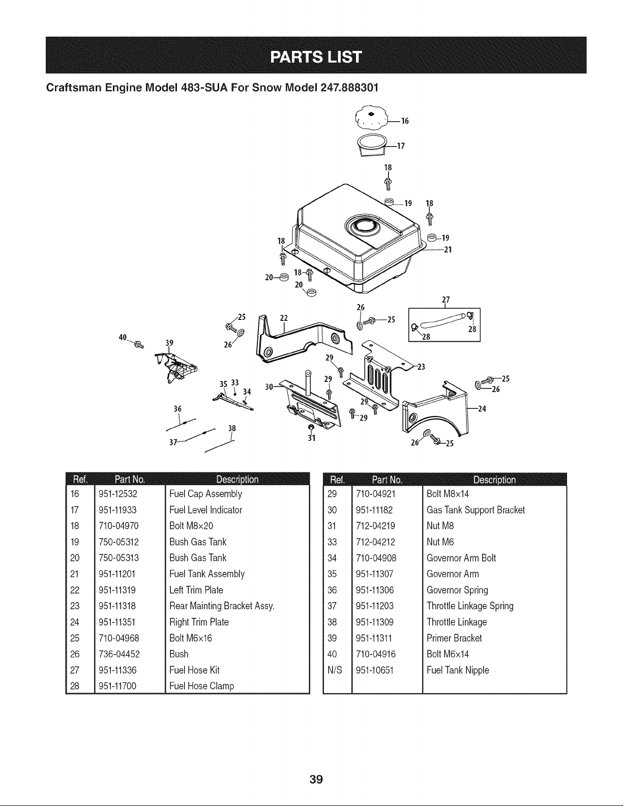
Craftsman Engine Model 483-SUA For Snow Model 247.888301
/25
%
40_ 39 26/
36
18
18 -19
_ 27
26
I
m
16
17
18
19
2O
21
22
23
24
25
26
27
28
951-12532
951-11933
710-04970
750-05312
750-05313
951-11201
951-11319
951-11318
951-11351
710-04968
736-04452
951-11336
951-11700
D = O
FuelCap Assembly
FuelLevelIndicator
BoltM8x20
BushGasTank
BushGasTank
FuelTankAssembly
LeftTrimPlate
RearMaintingBracketAssy.
RightTrimPlate
BoltM6x16
Bush
FuelHoseKit
FuelHoseClamp
m
29
30
31
33
34
35
36
37
38
39
40
N/S
710-04921
951-11182
712-04219
712-04212
710-04908
951-11307
951-11306
951-11203
951-11309
951-11311
710-04916
951-10651
D = O O
Bolt M8x14
GasTankSupportBracket
NutM8
NutM6
GovernorArm Bolt
GovernorArm
GovernorSpring
ThrottleLinkageSpring
ThrottleLinkage
PrimerBracket
Bolt M6x14
FuelTankNipple
39
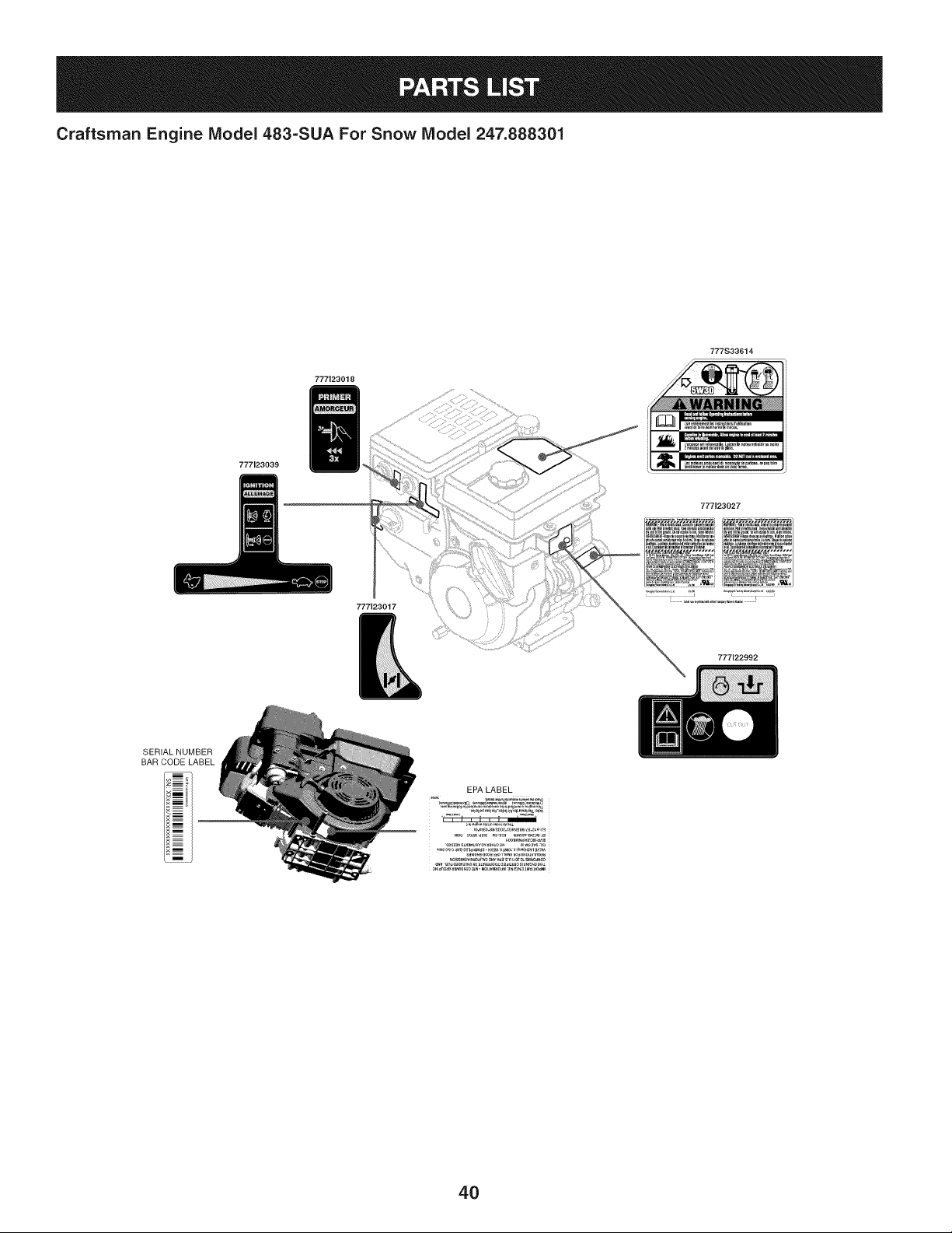
Craftsman Engine IViodel 483=SUA For Snow IViodel 247.888301
777123018
777S33614
777123039
777123017
777123027
777122992
SERIALNUMBER
BAR CODELABEL
EPA LABEL
4O
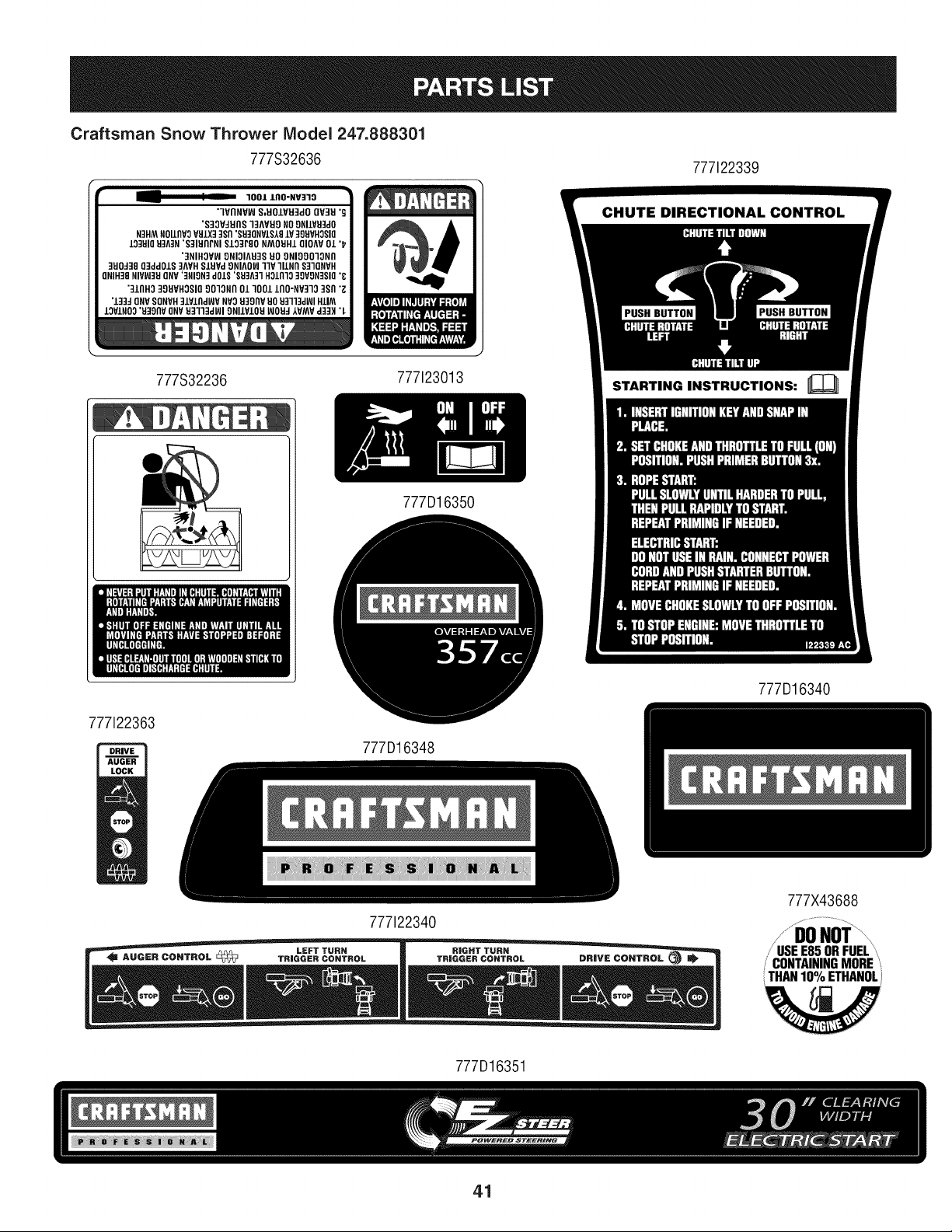
Craftsman Snow Thrower IVlodel 247.888301
777S32636
777122339
• -- [ -- 3001 lnO'NV:Z30 •
"WflNVW S,UOIVH3dO QV]H '_
'S30V_HflS ]3AVH9 NO9NllPU]dO
N3HM NOIlflPO VHIX3 3Sfl '$810NVISt81P 39UVHOSIO
103U10U3fi3N 'S31HflrNI $10]P80 NMOUH1 OlOAV 01 '_
'3NIHOVW 9NIOIAU3S HO 9NIOOO30Nfl
3H0338 O]dd01S ]AVH SlUVd 9NIAOW TIP 311Nil S33QNVH
]NIH38 NIVW]U QNV '3NION] d01S '8_A33 HOlfl]O 39VgN3SIQ'8
"]INH9 39HVHOSIO 90"lONn 013001 lnO'NP3"lO ]sfl "g
'133_ ONVSONVH]IVIfldWV NVOEI39nv 80 U3113d_l HIIM
lOVINO0 'u39nv ONVE3333dFJI 9NIIVIOU _OUd AVMV d33H "L
777S32236
777123013
777D16350
777122363
777D16348
777D16340
777122340
777X43688
777D16351
/ CONTAININGMORE
THAN10% ETHANOL
41
MTD CONSUMER GROUP INC (MTD), the California Air Resources Board (CARB)
and the United States Environment Protection Agency (U. S. EPA)
Emission Control System Warranty Statement
(Owner's Defect Warranty Rights and Obligations)
EMISSIONCONTROLSYSTEMCOVERAGEIS APPLICABLETOCERTIFIEDENGINESPURCHASEDIN CALIFORNIAIN 2005 ANDTHERE-
AFTER,WHICHARE USEDINCALIFORNIA,ANDTO CERTIFIEDMODELYEAR2005ANDLATERENGINESWHICHARE PURCHASEDAND
USEDELSEWHEREIN THE UNITEDSTATES.
Californiaandelsewherein the UnitedStatesEmissionControlDefectsWarrantyCoverage
The CaliforniaAir ResourcesBoard(CARB),U. S. EPAand MTDare pleasedto explaintheemissionscontrol systemwarrantyonyour modelyear
2006and latersmalloff-roadengine.In California,new smalloff-roadenginesmustbe designed,builtand equippedto meettheStatesanti-smog
standards.Elsewherein the UnitedStates,newnon-road,spark-ignitionenginescertifiedfor model2005and later,mustmeetsimilarstandardsset
forthby the U.S. EPA.MTDmustwarrantythe emissioncontrolsystemonyourenginefor the periodof timelistedbelow,providedtherehasbeen
noabuse,neglector impropermaintenanceof your smalloff-roadengine.
Youremissioncontrolsystemmayincludepartssuch as the carburetor,fuel-injectionsystem,the ignitionsystem,and catalyticconverter,fueltanks,
fuel lines,fuel caps,valves,canisters,filters,vaporhoses,clamps,connectors,and otherassociatedemission-relatedcomponents.
Wherea warrantableconditionexists,MTDwill repairyoursmalloff-roadengineat no cost to yourincludingdiagnosis,partsand labor.
MANUFACTURER'S WARRANTY COVERAGE:
Thisemissionscontrolsystemis warrantedfor twoyears.If anyemission-relatedpart on yourengine is defective,the part will berepairedor
replacedby MTD.
OWNER'S WARRANTY RESPONSIBILITIES:
As the smalloff-roadengineowner,youare responsibleforthe performanceof the requiredmaintenancelisted in your Owner'sManual.MTD
recommendsthatyou retainall yourreceiptscoveringmaintenanceson yoursmalloff-roadengine,but MTDcan not denywarrantysolelyfor the
lackof receiptsor foryour failureto ensurethe performanceto all scheduledmaintenance.
As the smalloff-roadengineowner,youshouldhoweverbeawarethat MTDmaydenyyour warrantycoverageif yoursmalloff-roadengineor part
hasfaileddue toabuse, neglect,impropermaintenanceor unapprovedmodifications.
Youare responsiblefor presentingyour smalloff-roadengineto an AuthorizedMTDServiceDealeras soonas a problemexists.Thewarranted
repairsshouldbe completedina reasonableamountof time,notto exceed30 days.
Ifyou haveanyquestionsregardingyourwarrantyrightsand responsibilities,you shouldcontacta MTDServiceRepresentativeat 1-800-800-7310
andaddressis MTDCONSUMERGROUP,RO.Box361131,ClevelandOH,44136-0019.
DEFECTS WARRANTY REQUIREMENTS FOR 1995 AND LATER SMALL OFF-ROAD ENGINES:
Thissectionappliesto 1995and later smalloff-roadengines.The warrantyperiodbeginson the datethe engineor equipmentis deliveredto an
ultimatepurchaser.
(a) GeneralEmissionsWarrantyCoverage
MTDmustwarrantto the ultimatepurchaserandeachsubsequentpurchaserthat the engineis:
(1)Designed,built,andequippedsoas to conformwith all applicableregulationsadoptedby the Air ResourcesBoardpursuantto its authorityin
Chapters1and 2,Part 5, Division26 of the Healthand SafetyCode; and
(2) Freefrom defectsin materialsandworkmanshipthatcausethe failureof a warrantedpart to beidenticalin all materialrespectsto the partas
describedin theengine manufacturer'sapplicationfor certificationfora periodof two years.
(b)The warrantyonemissions-relatedpartswill be interpretedas follows:
(1)Anywarrantedpart thatis not scheduledfor replacementas requiredmaintenanceinthe writteninstructionsrequiredby Subsection(c)
mustbewarrantedfor the warrantyperioddefinedinSubsection(a)(2). Ifany suchpartfailsduringthe periodof warrantycoverage,it mustbe
repairedor replacedby MTDaccordingto Subsection(4)below.Anysuch part repairedor replacedunderthewarrantymustbewarrantedfor
the remainingwarrantyperiod.
(2)Any warrantedpartthat is scheduledonlyfor regularinspectionin the writteninstructionsrequiredby Subsection(c) must bewarrantedfor
thewarrantyperioddefinedin Subsection(a)(2).A statementinsuch writteninstructionsto the effectof "repairor replaceas necessary"will
not reducethe periodof warrantycoverage.Anysuchpart repairedor replacedunderwarrantymustbe warrantedforthe remainingwarranty
period.
(3) Anywarrantedpartthat whichis scheduledfor replacementas requiredmaintenancein the writteninstructionsrequiredby Subsection(c)
mustbewarrantedfor the periodof timepriorto the first scheduledreplacementpointforthat part. If the part fails priorto thefirst scheduled
replacement,the part mustbe repairedor replacedby MTDaccordingto Subsection(4) below.Any suchpart repairedor replacedunder
warrantymustbewarrantedfor the remainderof the period priorto the first scheduledreplacementpointfor the part.
(4)Repairorreplacementofanywarrantedpartunderthewarrantyprovisionsofthisarticlemustbeperformedatnochargetotheownerata
warrantystation.
(5)NotwithstandingtheprovisionsofSubsection(4)above,warrantyservicesorrepairsmustbeprovidedatallMTDdistributioncentersthat
arefranchisedtoservicethesubjectengines.
(6)Theownermustnotbechargedfordiagnosticlaborthatleadstothedeterminationthatawarrantedpartisinfactdefective,providedthat
suchdiagnosticworkisperformedatawarrantystation.
(7)Theenginemanufacturerisliablefordamagestootherenginecomponentsproximatelycausedbyafailureunderwarrantyofanywarranted
part.
(8)Throughouttheengine'swarrantyperioddefinedinSubsection(a)(2),MTDwillmaintaina supplyofwarrantedpartssufficienttomeetthe
expecteddemandforsuchparts.
(9)Anyreplacementpartmaybeusedintheperformanceofanywarrantymaintenanceorrepairsandmustbeprovidedwithoutchargetothe
owner.SuchusewillnotreducethewarrantyobligationsofMTD.
(10)Add-onormodifiedpartsthatarenotexemptedbytheAirResourcesBoardmaynotbeused.Theuseofanynon-exemptedadd-onor
modifiedpartsshallbegroundsfordisallowingawarrantyclaimmadeinaccordancewiththisarticle.Theenginemanufacturershallnotbe
liableunderthisarticletowarrantfailuresofwarrantedpartscausedbytheuseofnon-exemptedadd-onormodifiedpart.
(c) MTDwill includea copyof the followingemissionwarrantyparts list with each newengine,usingthose portionsof the list applicableto the
e__&gine.
(1)FuelMeteringSystem
• Coldstart enrichmentsystem(soft choke)
,,Carburetorandinternalparts
• Fuel Pump
• FuelTank
(2)Air InductionSystem
• Aircleaner
• Intakemanifold
(3) IgnitionSystem
• Sparkplug(s)
• MagnetoIgnitionSystem
(4)ExhaustSystem
Catalyticconverter
• SAI (Reedvalve)
(5) MiscellaneousItemsUsedin AboveSystem
Vacuum,temperature, position,time sensitivevalvesand switches
Connectorsandassemblies
(6) Evaporativecontrol
• Fuel Hosecertifiedfor ARBevaporativeemissionof 2006.
• Fuel HoseClamps
Tetheredfuel cap
Carboncanister
Vaporlines
GD0C-100174Rev.B
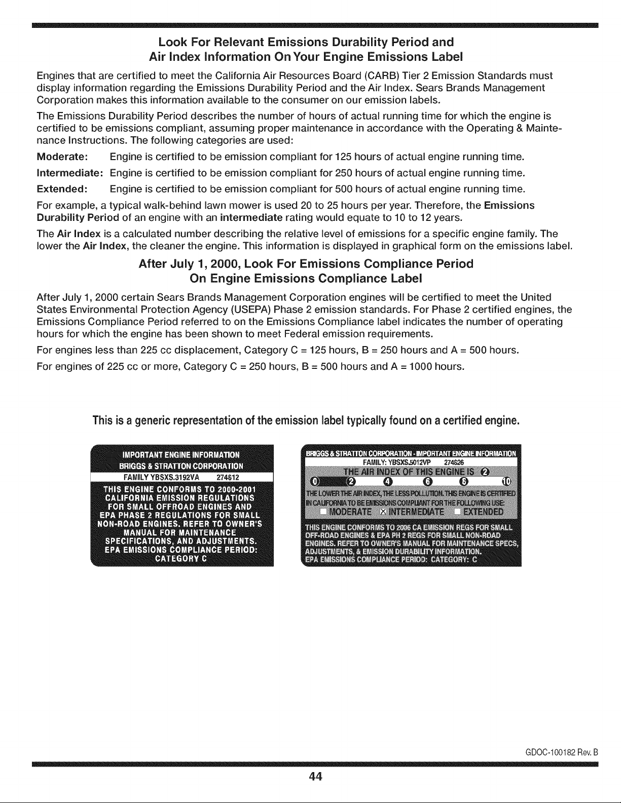
Look For Relevant Emissions Durability Period and
Air index information On Your Engine Emissions Label
Engines that are certified to meet the California Air Resources Board (CARB) Tier 2 Emission Standards must
display information regarding the Emissions Durability Period and the Air Index. Sears Brands Management
Corporation makes this information available to the consumer on our emission labels.
The Emissions Durability Period describes the number of hours of actual running time for which the engine is
certified to be emissions compliant, assuming proper maintenance in accordance with the Operating & Mainte-
nance Instructions. The following categories are used:
Moderate: Engine is certified to be emission compliant for 125 hours of actual engine running time.
Intermediate: Engine is certified to be emission compliant for 250 hours of actual engine running time.
Extended: Engine is certified to be emission compliant for 500 hours of actual engine running time.
For example, a typical walk-behind lawn mower is used 20 to 25 hours per year. Therefore, the Emissions
Durability Period of an engine with an intermediate rating would equate to 10 to 12 years.
The Air index is a calculated number describing the relative level of emissions for a specific engine family. The
lower the Air Index, the cleaner the engine. This information is displayed in graphical form on the emissions label.
After July 1,2000, Look For Emissions Compliance Period
On Engine Emissions Compliance Label
After July 1, 2000 certain Sears Brands Management Corporation engines will be certified to meet the United
States Environmental Protection Agency (USEPA) Phase 2 emission standards. For Phase 2 certified engines, the
Emissions Compliance Period referred to on the Emissions Compliance label indicates the number of operating
hours for which the engine has been shown to meet Federal emission requirements.
For engines less than 225 cc displacement, Category C = 125 hours, B = 250 hours and A = 500 hours.
For engines of 225 cc or more, Category C = 250 hours, B = 500 hours and A = 1000 hours.
This is a generic representation of the emission label typically found on a certified engine.
FAMILYYBSXS.3192VA 274812
GDOC-100182Rev.B
44
Congratulations on making a smart purchase. Your new Craftsman® product is designed and
manufactured for years of dependable operation. But like all products, it may require repair
from time to time. That's when having a Repair Protection Agreement can save you money and
aggravation.
Here's what the Repair Protection Agreement* includes:
[] Expert service by our 10,000 professional repair specialists
[] Unlimited service and no charge for parts and labor on all covered repairs
[] Product replacement up to $1500 if your covered product can't be fixed
[] Discount of 25% from regular price of service and related installed parts not covered by the
agreement; also, 25% off regular price of preventive maintenance check
[] Fast help by phone - we call it Rapid Resolution - phone support from a Sears representative.
Think of us as a "talking owner's manual."
Once you purchase the Repair Protection Agreement, a simple phone call is all that it takes for you
to schedule service. You can call anytime day or night, or schedule a service appointment online.
The Repair Protection Agreement is a risk-free purchase. If you cancel for any reason during the
product warranty period, we will provide a full refund. Or, a prorated refund anytime after the
product warranty period expires. Purchase your Repair Protection Agreement today!
Some limitations and exclusions apply. For prices and additional information in the U.S.A.
call 1=800=827=6655.
*Coverage in Canada varies on some items. For full details call Sears Canada at 1=800=361=
6665.
Sears Installation Service
For Sears professional installation of home appliances, garage door openers, water heaters, and
other major home items, in the U.S.A. or Canada call 1=800=4=MY=HOME®.
45
Declaraci6n de garantia ............................ Pagina 46
Practicas operaci6n seguras ..................... Pagina 47
Montaje ...................................................... Pagina 51
Operaci6n .................................................. Pagina 57
Servicio y Mantenimiento .......................... Pagina 62
Almacenamiento fuera de temporada ....... Pagina 69
Soluci6n de problemas .............................. Pagina 70
Acuerdo de protecci6n para reparaciones .... Pagina 75
Lista de piezas ........................................... Pagina 26
NOmero de servicio ................................... Cubierta
posterior
GARANTiA PROFESIONAL TOTAL CRAFTSMAN POR DOS AltOS
PORDOSANOSapartir dela fechade cornpra,esteproductoest&garantizadocontracualquierdefectode materialo rnanode obra.El
productodefectuosorecibir_,la reparaci6no la sustituci6ngratuitasi la reparaci6nnoest,.disponible.
Estagaranfias61otiene vigenciapot un aSodesdela fechade cornprasi este productosehan utilizadoalgunavez,rnientrasquela prestaci6n
de servicioscornercialeso si se alquilaa otrapersona.
Paraobtener informacibndetallada coberturade la garantiaparaobtener la reparacibno reemplazo,visite el sitio web:
www.craftsman.com
Esta garantia cubre SOLO defectos en material y habilidad. La cobertura de garantiano incluye:
• Elernentosreutilizablesque puedengastarseporel uso normaldentrodel periodode garanfia,incluso,pero no lirnitadosparabarrenas,
barrenarernos,cortadoresdernovirniento,patinarzapatos,platode afeitado,esquilanalfileres,bujia,filtro deaire, cinturones,y filtro del
aceite.
• Revisi6ndernantenirnientoest_.ndar,carnbiosde aceite,o puestasa punto.
• Reernplazodeneurn_.ticoo reparaci6ncausadaporpinchazosdesdefuerade objetos,cornou_as,espinas,tocones,ocristal.
• Neurn_.ticoo reernplazode ruedao reparaci6nqueresultade ropanormal,accidente,u operaci6nirnpropiao rnantenirniento.
• Las reparacionesnecesariasdebidoal abusodeoperador,inclusoperono lirnitadoparada_arcausadoafectandoobjetosque doblanel
marcoo la barrenaeje, o el sobreexcesode velocidaddel motor.
• Reparacionesnecesariasdebidoa negligenciadeloperador,induyendoentre otros,da_osrnec_.nicoy el_ctricoocasionadopor un
alrnacenarnientonoapropiado,falla pot el usode aceitede grado y/o cantidadnoapropiadao fallapor no dar rnantenirnientoal equipode
acuerdocon las instruccionescontenidasen el manualdeloperador.
• Lirnpiezao reparacionesal motor(sisternade combustible)provocadasporun combustiblecontarninadouoxidado(viejo).Engeneral,el
combustibledebeutilizarseen un periodono mayorde 30dias a partirde su adquisici6n.
• Elernpejorarnientonormaly la ropade losfinesexteriores,o productoetiquetanel reernplazo.
Estagarantialeotorgaderechoslegalesespecificos,pero ustedpodria gozarde otrosderechosen raz6nde su lugarde residencia.
Sears Brands Management Corporation, Hoffman Estates, IL 60179
Tipode aceitedel motor:
Capacidaddeaceitedel motor:
Capacidaddecombustible:
Bujfas:
Separaci6nde lasbujias:
SAE 5W-30
37 onzas
Aprox. 5 cuartos
F6RTC
.020" a .030"
N_merode modelo ..........................................................
N_merode sede ..............................................................
Fechade compra .............................................................
Registrearriba el nOrnerodel rnodelo,elnOrnerode seriey lafecha
decornpra
© KCD IP,LLC
46
Lapresenciade este sfrnboloindicaque setrata de instrucciones
irnportantesde seguridadque se deben respetarparaevitar
poneren peligrosu seguridadpersonaly/o materialy lade otras
personas.Leay siga todaslas instruccionesde este manualantes
de poneren funcionarnientoesta rn_.quina.Si no respetaestas
instruccionespodrfaprovocarlesionespersonales.Cuandoveaeste
sfrnbolo,ipresteatenci6na la advertencia!
PROPOSICION 65 DE CALIFORNIA
Elescapedel motorde este producto,algunosde suscornponentes
y algunoscornponentesdelvehfculocontieneno liberansustancias
qufrnicasqueel estado de Californiaconsideraque puedenproducir
c_.ncer,defectosde nacirnientou otros problernasreproductivos.
Estarn_.quinarueconstruidaparaseroperadadeacuerdocon
las reglasde seguridadcontenidaseneste manual.AI igualque
concualquiertipo deequipornotorizado,undescuidoo error por
partedeloperadorpuedeproducirlesionesgraves.Esta rn_.quina
es capazde arnputarrnanosy piesy dearrojarobjetoscon gran
fuerza.Deno respetarlas instruccionesde seguridadsiguientesse
puedenproducirlesionesgraveso la rnuerte.
Su responsabilidad--Restrinja el usode estarn_.quina
rnotorizadaalas personasque lean,cornprendany respetenlas
advertenciase instruccionesqueaparecenen este manualyen la
rn_.quina.
iGUARDEESTASINSTRUCCIONES!
CAPACITACI6N
• Lea,entienday curnplatodaslas instruccionesincluidasen
la rn_.quinayen los rnanualesantesdernontarlay utiNzarla.
Guardeestemanualen un lugarseguroparaconsultasfuturasy
peri6dicas,asf cornoparasolicitarrepuestos.
• Leael ManualdelOperadory sigatodaslas advertenciase
instruccionesde seguridad.Elfracasode hacerasf puedecausar
la heridaseriaal operadory/o personaspresentes.
• Farniliarfcesecontodoslos controlesy con el usoadecuado
delos rnisrnos.Sepa c6rnodetenerla rn_.quinay desactivarlos
controlesr_.pidarnente.
• No perrnitanuncaque los ni_osrnenoresde 14a_osutilicen
estarn_.quina.Los ni_osde 14a_osen adelantedeben leer y
entenderlas instruccionesde operaci6ny norrnasdeseguridad
contenidasen este manual,yen la rn_.quinaydebenser entrena-
dosy supervisadosporun adulto.
• Nuncaperrnitaquelos adultosoperenesta rn_.quinasin recibir
antesla instrucci6napropiada.
• Losobjetosarrojadosporla rn_.quinapuedenproducirlesiones
graves.Planifiqueel patr6nenel queva air arrojandonievepara
evitarque la descargade materialse realicehacialos carninos,
los observadores,etc.
• Mantengaa losobservadores,ayudantes,rnascotasy ni_ospor
Io rnenosa 75 piesde la rn_.quinarnientrasla rnisrnaest,.en
funcionarniento.Detengala rn_.quinasi alguienseacerca.
• Seaprecavidopara evitarpatinarseo caerseespecialrnente
cuandooperala rn_.quinaen reversa.
PR E PARATIVO S
Inspeccionerninuciosarnenteel _.readondeutilizar_,el equipo.Saque
todoslos felpudos,peri6dicos,trineos,tablas,cablesy otrosobjetos
extra_oscon los quepodrfatropezaro que podrfanser arrojadospor
labarrena/irnpulsor.
• Paraprotegerselosojos utilice siernpreanteojosoantiparras
de seguridadrnientrasopera la rn_.quinao rnientrasla ajusta
o repara.Losobjetosarrojadosquerebotanpuedenproducir
lesionesocularesgraves.
• Noopere la rn_.quinasin la vestirnentaadecuadaparaestar al
airelibreen invierno.No utilicealhajas,bufandaslargasu otras
prendassueltasquepodrfanenredarseen las partes rn6viles.
UtiNceun calzadoespecialpara superficiesresbaladizas.
• Useun prolongadory untornacorrientedetrescablescon
conexi6na tierraparatodas las rn_.quinascon rnotoresde
encendidoel_ctrico.
• Ajustela alturade lacaja deltornacorrientepara Nrnpiarla grava
o las superficiescon piedrastrituradas.
• Desengranetodaslas palancasde controlantesde arrancarel
motor.
• Nuncaintenterealizarajustesrnientrasel motorest,.en rnarcha
exceptoen los casosespecfficarnenterecornendadosen el
manualdeloperador.
• Dejeque el motor y la rn_.quinase adaptena laternperatura
exteriorantesde cornenzara sacarla nieve.
4.7
Manejo seguro de la gasolina
Paraevitarlesionespersonales0 daSosrnaterialestengarnucho
cuidadocuandotrabajecon gasolina.Lagasolinaes surnarnente
inflarnabley sus vaporespuedencausarexplosiones.Si se derrarna
gasolinaencirna0 sobrela ropase puedelesionargravernenteya que
se puedeincendiar. L&vesela piely c&rnbiesede ropade inrnediato.
• Utilices610los recipientesparagasolinaautorizados.
• Apaguetodos los cigarrillos,cigarros,pipasy otras fuentesde
cornbusfi6n.
• Nuncacarguecombustibleen la rn&quinaen unespaciocerrado.
• Nuncasaquela tapadel combustibleni agreguecombustible
rnientrasel motorest&caliente0 en rnarcha.
• Dejequeel motorse enfrieporI0 rnenosdos rninutosantesde
volvera cargarcombustible.
• Nuncalleneen excesoel dep6sitodecombustible.Lleneel
tanquea no rn&sde1/2pulgadapordebajode la basedelcuello
de Ilenadodejandoespacioparala dilataci6ndeIcombustible.
• Vuelvaa colocarla tapade la gasoiinay aj_stelabien.
• Lirnpieel combustiblequese hayaderrarnadosobreel motory el
equipo.Trasladela rn&quinaa otra zona.Espere5 rninutosantes
deencenderel motor.
• Nuncaalrnacenela rn&quina0 el recipientede combustibleen
unespaciocerradodondehayafuego,chispas0 luz piloto(por
ejernplo,hornos,calentadoresdeagua,calefactores,secadores
de ropa,etc.).
• Dejequela rn_.quinase enfriepor Io rnenos5 rninutosantesde
guardarla.
• NuncaIlenelos recipientesen el interiordeun vehiculoo carni6n
ocaja de rernolquecon recubrirnientospl_.sticos.Coloque
siernprelos recipientesen el pisoy lejosdelvehiculoantesde
Ilenarlos.
• Sies posible,retireel equipoa gasolinadel carni6no rernolque
y II_neloen el suelo.Siestonoes posible,Ileneel equipoen un
rernolquecon contenedorport_.til,envezde desdeuna boquilla
dispensadoradegasolina.
• Mantengala boquilladispensadoraen contactocon el hordedel
dep6sitode combustibleo con la aberturadel recipienteentodo
rnornento,hastaterrninarlacarga. No utiliceun dispositivode
apertura/cierrede boquilla.
FUNCIONANIIENTO
• No pongalas rnanoso los piescerca de las piezasrotatorias,
en la cajade la barrena/ irnpulsoro en el rnontajedelcanalde
descarga.Hacercontactocon piezasgiratoriaspuederesultaren
laarnputaci6nde rnanoso pies.
• La palancade controlde la barrena/ irnpulsores un dispositivo
de seguridad.Nuncaevite su funcionarniento.De hacerlola
operaci6nde la rn_.quinaes riesgosay puedeocasionarlesiones.
• Las palancasde control debenfuncionarbien en arnbasdirec-
cionesy regresarautorn_.ticarnentea la posici6nde desengrane
cuandose lassuelta.
• Nuncaoperela rn_.quinasi falta un rnontajedel canalo si el
rnisrnoest,.daSado.Mantengatodos losdispositivosde seguri-
daden su lugary en funcionarniento.
• Nuncaenciendael motor en espacioscerradoso en unazona
con pocaventilaci6n.Elescapedel motorcontienernon6xidode
carbono,ungas inodoroy letal.
• Noutilice la rn_.quinabajola influenciadel alcoholo las drogas.
• El silenciadory el motorse calientany puedencausarquernadu-
ras.Nolos toque.Mantengaa los niSosalejados.
• Seasurnarnenteprecavidocuandoopere la rn_.quinasobreuna
superficiecon gravaocuandola cruce.Mant_ngasealerta porsi
se presentanpeligrosocultoso tr_.nsito.
• Tengacuidadocuandocarnbiede direcci6no cuandoopere
la rn_.quinaenpendientes.Nouse la rn_.quinaen pendientes
pronunciadas.
• Planifiqueel patr6nen el queva air arrojandonieveparaevitar
que la descargade materialse produzcahacialas ventanas,
las paredes,losautorn6viles,etc.y evitarasi posiblesdaSos
rnaterialeso lesionesproducidaspor los rebotes.
• Nuncadirija la descargahacialos niSos,los observadoreso las
rnascotasni deje que nadiese pare delantede la rn_.quina.
• Nosobrecarguela capacidadde la rn_.quinatratandode sacarla
nievernuyr_.pidarnente.
• Nuncaopereesta rn_.quinasin buenavisibilidado ilurninaci6n.
Siernpredebeestar segurode queest,.bienafirrnadoy su-
jetandofirrnernentelas rnanijas.Carnine,nuncacorra.
• Cortela corrientea la barrena/ irnpulsorcuandotransportela
rn_.quinao cuandolarnisrnano est,. en uso.
• Nuncaoperela rn_.quinaa alta velocidadde desplazarniento
sobresuperficiesresbaladizas.Mirehaciaabajoy haciaatr_.sy
tengacuidadocuandovayarnarchaatr_.s.
• Si la rn_.quinacornenzaraa vibrarde rnaneraanorrnal,detengael
motor,desconecteel cablede labujia y p6ngalade rnaneraque
hagarnasacontra el motor.Inspeccionela rn_.quinarninuciosa-
rnenteparaver si est,.daSada.Reparetodos los daSosantesde
encendery operarla rn_.quina.
• Desengranetodas las palancasde controly detengaelmotor
antesde dejar la posici6nde operaci6n(detr_.sdelas rnanijas).
Espereaque labarrena/ irnpulsorse detengapor cornpleto
antesde destaparel rnontajedel canalo realizarajustese
inspecciones.
• Nuncapongalas rnanosen las aberturasde descargao de
recolecci6n.Utilicesiernprela herrarnientadelirnpiezaquese
adjuntaparadestaparla aberturade descarga.Nodestapeel
rnontajedelcanal rnientrasel motorest,. en funcionarniento.
Antesde destaparlo,apagueel motory perrnanezcadetr_.sde las
rnanijashastaque todaslas partes rn6vilesse hayandetenido.
• Uses61ounionesy accesoriosaprobadospor el fabricante(por
ejernplo,pesasparalas ruedas,cadenaspara los neurn_.ticos,
cabinas,etc.).
48
• Paraencenderel motor,jale de lacuerdalentarnentehasta que
sientaresistencia,luegojale r_.pidarnente.Elreplieguer_.pidode
la cuerdade arranque(tensi6nde retroceso)lejalar_,la rnanoy
el brazohaciael motorrn_.sr_.pidode Io que usted puedesoltar.
El resultadopuedenserhuesosrotos,fracturas,hernatornaso
esguinces.
• Si se presentansituacionesque no est_.nprevistasen este
manual,seacuidadosoy use el sentidocornOn.
• Porrazonesde seguridaddentrode lagarantia,operaci6no
rnantenirnientode las preguntas,o parapedir piezasy el servicio
dehorario,Ilarneal 1-800-4-MY-HOME.
MANTENIMIENTO Y ALMACENAMIENTO
• Nuncaalterelos dispositivosde seguridad.Controleperi6dica-
rnentequefuncionencorrectarnente.Rernitasea las secciones
demantenirnientoy ajustede estemanual.
• Antesde realizarla lirnpieza,repararo revisarla rn_.quina,
desengranetodas laspalancasde controly detengael motor.
Esperea que la barrena/ irnpulsorse detengaporcornpleto.
Desconecteel cabledela bujfay p6ngalohaciendornasacontra
el motorpara evitarque se enciendaaccidentalrnente.
• Controlefrecuenternenteque todos lospernosy tornillosest_n
bienajustadosparacornprobarquela rn_.quinase encuentra
encondicionessegurasde funcionarniento.Adern_.s,haga una
inspecci6nvisual de larn_.quinaparaverificarsi est,.da_ada.
• No carnbielaconfiguraci6ndel reguladordel motorni acelere
dernasiadoel rnisrno.El reguladordel motorcontrolala velocidad
rn_.xirnaseguradefuncionarnientodel motor.
• Las placasde raspadoy las zapatasantideslizantesquese
usancon la rn_.quinaquitanievese desgastany se da_an.
Paraprotegersu seguridad,verifiquefrecuenternentetodos los
cornponentesy reernpl_.celoss61ocon partesde los fabricantes
deequiposoriginales(OEM).iEI usode piezasque no curnplen
con lasespecificacionesdelequipooriginalpuederesultaren
rendirnientoinadecuadoadern_.sde poneren riesgola seguridad!
• Reviselas palancasde controlperi6dicarnenteparaverificar
queengraneny desengranenadecuadarnentey ajOstelossi es
necesario.Consultela secci6nde ajustesde este manualdel
operadorparaobtenerinstrucciones.
• Mantengao reernplacelasetiquetasde seguridade instrucciones
segQnseanecesario.
• Respetelas norrnasreferentesa ladisposici6ncorrectay las
reglarnentacionessobregasolina,aceite,etc. para protegerel
medicarnbiente.
• Antesdealrnacenarla rn_.quinaenci_ndalaunosrninutospara
sacarla nieveque hayaquedadoen larnisrnay paraevitarasi
quese congelela barrena/irnpulsor.
• SegOnla Cornisi6nde Seguridadde Productosparael Consurni-
dorde los EstadosUnidos(CPSC)y la Agenciade Protecci6n
Arnbientalde los EstadosUnidos(EPA),esteproductotieneuna
vida Qtilmediadesiete(7)a_os,6 60 horasdefuncionarniento.
AI finalizarlavida Otilmedia,adquieraunarn_.quinanuevao
hagainspeccionaranualrnente_stapor un distribuidordeservicio
autorizadoparacerciorarsede que todoslos sisternasrnec_.nicos
y deseguridadfuncionancorrectarnentey no tienenexcesivo
desgaste.Si no Iohace,puedenproducirseaccidentes,lesiones
o rnuerte
• Nuncaalrnacenela rn_.quinao el recipientede combustibleen un
espaciocerradodondehayafuego,chispaso luz pilotocornopor
ejernplo,calentadoresde agua,hornos,secadoresde ropa,etc.
• Consultesiernpreel manualdel operadorparaobtener
instruccionesadecuadaspara el alrnacenarnientofuerade
ternporadaVerifiquefrecuenternentelaIfneade combustible,el
tanque,el tap6n,y losaccesoriosbuscandorajaduraso perdidas.
Reernplacede ser necesario.
• Nod_ arranqueal motorsi no est,. labujiade encendido.
NO MODIFIQUE EL MOTOR
Paraevitarlesionesgraveso la rnuerte,no rnodifiqueel motorbajo
ningunacircunstancia.Si carnbiala configuraci6ndel reguladorel
motorpuededescontrolarsey operara velocidadesinseguras.Nunca
carnbielaconfiguraci6nde f_.bricadel reguladordel motor.
AVISO REFERIDO A EMISIONES
Losrnotoresqueest&ncertificadosy curnplencon las regulaciones
de ernisionesfederalesEPAy de CaliforniaparaSORE(Equipos
peque_ostodoterreno)est_.ncertificadosparaoperarcon gasolina
cornOnsinplornoy puedenincluirlossiguientessisternasde control
de ernisiones:Modificaci6nde motor(EM) y catalizadorde tresvias
(TWO)si est_.nequipadosde esa rnanera.
GUARDACHISPAS
Estarn&quinaest,.equipadacon un motorde cornbusti6ninternay
nodebeser utilizadaen o cercade unterrenoagrestecubiertopor
bosque,rnalezaso hierba exceptosi el sisternade escapedelmotor
est,.equipadocon unarnortiguadorde chispasque curnplaconlas
leyeslocaleso estatalescorrespondientes,encaso de haberlas.
Sise utilizaun arnortiguadordechispasel operadorIo debe rnantener
en condicionesde usoadecuadas.Enel Estadode Californialas
rnedidasanteriorrnenternencionadassonexigidaspor ley (Arficulo
4442del C6digode RecursosPOblicosde California).Es posible
queexistanleyessirnilaresenotros estados.Lasleyesfederalesse
aplicanenterritoriosfederales.
Puedeconseguirelarnortiguadorde chispasparael silenciadora
travesde sudistribuidorautorizadode rnotoreso poni_ndoseen
contactocon eldepartarnentodeservicios.
49
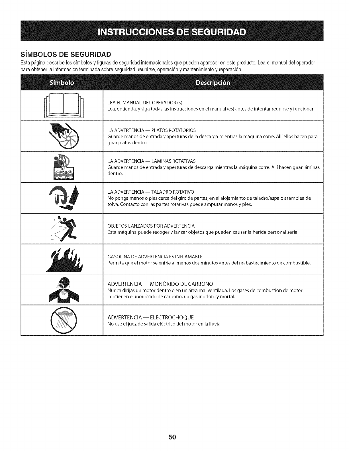
SiMBOLOS DE SEGURIDAD
Estap_ginadescribelossimbolosy figurasde seguridadinternacionalesquepuedenaparecerenesteproducto.Lea el manualdeloperador
)araobtenerla informaci6nterminadasobreseguridad,reunirse,operaci6ny mantenimientoy reparaci6n.
i
i
LEA EL MANUAL DEL OPERADOR (S)
Lea, entienda, y siga todas las instrucciones en el manual (es) antes de intentar reunirse y funcionar.
LA ADVERTENCIA -- PLATOS ROTATORIOS
Guarde manos de entrada y aperturas de la descarga mientras la m_iquina corre. Alli ellos hacen para
girar platos dentro.
LA ADVERTENCIA- LAMINAS ROTATIVAS
Guarde manos de entrada y aperturas de descarga mientras la m_iquina corre. Alli hacen girar I_iminas
dentro.
LA ADVERTENCIA -- TALADRO ROTATIVO
No ponga manos o pies cerca del giro de partes, en el alojamiento de taladro/aspa o asamblea de
tolva. Contacto con las partes rotativas puede amputar manos y pies.
OBJETOS LANZADOS POR ADVERTENCIA
Esta m_iquina puede recoger y lanzar objetos que pueden causar la herida personal seria.
GASOLINA DE ADVERTENCIA ESINFLAMABLE
Permita que el motor se enfrie al menos dos minutos antes del reabastecimiento de combustible.
ADVERTENCIA -- MONOXIDO DE CARBONO
Nunca dirijas un motor dentro o en un _irea mal ventilada. Los gases de combusti6n de motor
contienen el mon6xido de carbono, un gas inodoro y mortal.
ADVERTENCIA -- ELECTROCHOQUE
No use eljuez de salida el_ctrico del motor en la Iluvia.
5O
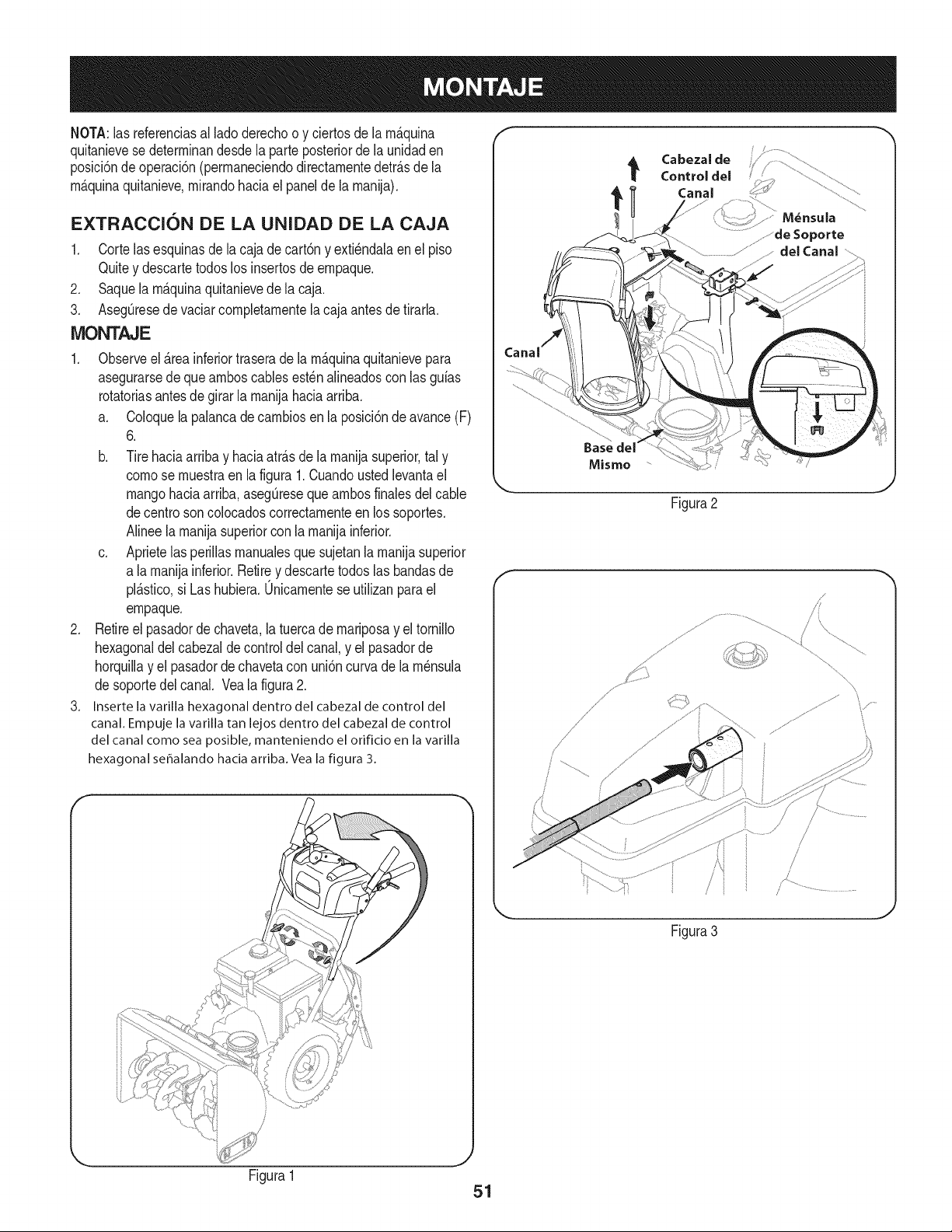
NOTA:las referenciasal ladoderechoo y ciertosde la rn&quina
quitanievese deterrninandesdela parteposteriorde la unidaden
posM6nde operaci6n(perrnaneciendodirectarnentedetr&sde la
rn&quinaquitanieve,rnirandohaciael panelde la rnanija),
EXTRACCION DE LA UNIDAD DE LA CAJA
1. Cortelasesquinasdela cajade cart6ny exti_ndalaenel piso
Quitey descartetodoslos insertosde ernpaque.
2. Saquela rn_.quinaquitanievede la caja.
3. AsegQresede vaciarcornpletarnentela cajaantesde tirarla.
iVIONTAJE
1. Observeel _.reainferiortraserade la rn_.quinaquitanievepara
asegurarsede que arnboscablesest_n alineadoscon las guias
rotatoriasantes de girar la rnanijahaciaarriba.
a. Coloquela palancadecarnbiosen la posici6ndeavance(F)
6.
b. Tirehaciaarriba y haciaatrAsde larnanijasuperior,tal y
cornose rnuestraen la figura1.Cuandoustedlevantael
mangohaciaarriba,asegQresequearnbosfinalesdel cable
decentrosoncolocadoscorrectarnenteen lossoportes.
Ninee la rnanijasuperiorconla rnanijainferior.
c. Aprietelasperillasrnanualesque sujetanla rnanijasuperior
a la manijainferior.Retirey descartetodoslas bandasde
plAstico,si Las hubiera.0nicarnentese utilizanparael
ernpaque.
2. Retireel pasadordechaveta,latuercade rnariposay eltornillo
hexagonaldel cabezalde control delcanal,y el pasadorde
horquillay el pasadorde chavetacon uni6ncurva de larn_nsula
desoportedel canal. Veala figura2.
3. Insertela varillahexagonaldentro del cabezalde control del
canal.Empujelavarillatan lejosdentro del cabezalde control
del canalcomo sea posible, manteniendo el orificio en lavarilla
hexagonalseffalandohaciaarriba.Yeala figura 3.
f Cabezal de
Control del
t Canal
M_nsula
Basedel
Mismo
J
Figura2
J
Figura3
Figura1
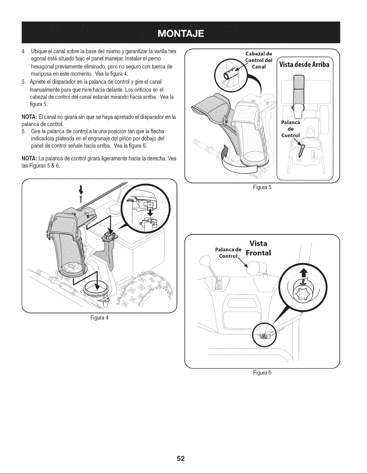
4. Ubiqueelcanalsobrelabasedelmismoygarantizarlavarillahex
agonalest,.situadobajoelpanelmanejar.Instalarelperno
hexagonalpreviamenteeliminado,peronosegurocontuercade
mariposaenestemomento.Vealafigura4.
5. Aprieteeldisparadorenlapalancadecontrolygireelcanal
manualmenteparaquemirehaciadelante.Losorificiosenel
cabezaldecontroldelcanalestar_.nmirandohaciaarriba.Veala
figura5.
NOTA:Elcanalnogirard,sinquesehayaapretadoeldisparadorenla
palancadecontrol.
6. Girelapalancadecontrolalaunaposici6ntanquelaflecha
indicadoraplateadaenelengranajedelpi56npordebajodel
paneldecontrolseSalehaciaarriba.Vealafigura6.
NOTA:Lapalancadecontrolgirard,ligeramentehacialaderecha.Vea
lasFiguras5&6.
f
Control
Figura4
Figura5
f
Vista
Figura6
52
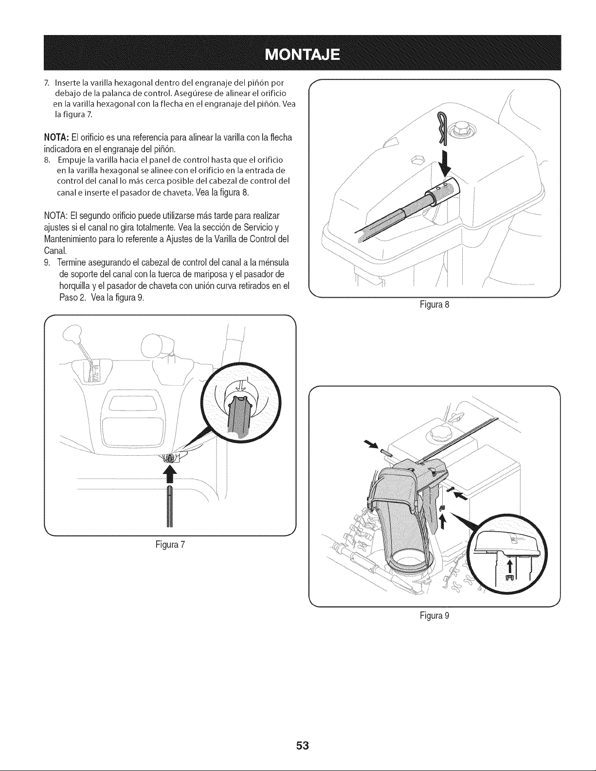
7. Inserte la varilla hexagonal dentro del engranaje del pih6n por
debajo de la palanca de control. Asegurese de alinear el orificio
en la varilla hexagonal con la flecha en el engranaje del piB6n. Vea
la figura 7.
NOTA:El orificioes una referenciaparaalinear la varillacon la flecha
indicadoraen el engranajedel pi56n.
8. Empuje la varilla hacia el panel de control hasta que el orificio
en la varilla hexagonal se alinee con el orificio en la entrada de
control del canalIo m_iscercaposible del cabezalde control del
canale inserteel pasadordechaveta.Veala figura8.
NOTA:Elsegundoorificiopuedeutilizarsem&stardepara reaNzar
ajustessi el canalno giratotalmente.Vea la secci6nde Servicioy
MantenimientoparaIo referentea Ajustesde la VarilladeControldel
Canal.
9. Termineasegurandoel cabezaldecontroldel canala lam_nsula
desoportedel canalcon la tuercade mariposay el pasadorde
horquillay el pasadorde chavetacon uni6ncurva retiradosen el
Paso2. Vealafigura9.
r
/
/
/ / ...............................'_ i
Figura7
/
/
Figura8
Figura 9
./
J
J
53
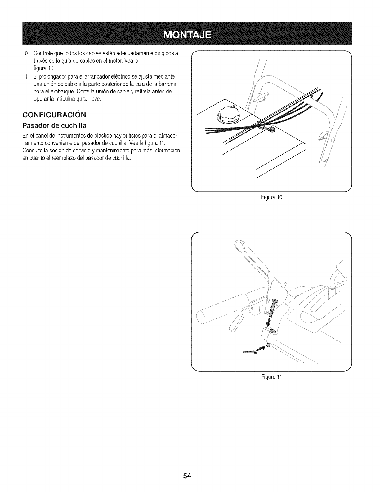
10. Controleque todosloscablesest_nadecuadarnentedirigidosa
travesde la gufadecablesenel motor.Veala
figura 10.
11. El prolongadorparael arrancadorel_ctricose ajustarnediante
unauni6nde cablea la parteposteriorde la cajade la barrena
paraelernbarque.Cortela uni6nde cable y refirelaantesde
operarla rn_.quinaquitanieve.
CONFIGURACI6N
Pasador de cuchilla
Enel panelde instrurnentosde pl_.sticohay orificiospara el alrnace-
narnientoconvenientedelpasadorde cuchilla.Vea la figura 11.
Consultela secionde servicioy rnantenirnientopararn_.sinforrnaci6n
encuantoel reernplazodelpasadorde cuchiNa.
/
i
!
.J
Figura10
f
Figura11
54

Herramienta de Limpieza del Canal
Hayuna herrarnientade lirnpiezadel canal iajustadaa la parte
superiorde la caja de la barrenaconun pasadorde ensarnNado.Vea
la figura12.La herrarnientaest&diseSadaparalirnpiarel hMo y la
nievedel rnontajede un canal. Este productose sujetarnedianteuna
uni6nde cableen laf&brica.Cortela uni6nde cableantesdeoperar
la rnAquinaquitanieve.
Nuncause susrnanosparaliberarun rnontajede canaltapado.
Apagueel motory perrnanezcadetr_.sde las rnanijashastaquetodas
las partesrn6vilesse hayandetenidoantesde utilizar la herrarnienta
delirnpiezaparalirnpiarel rnontajedel canal.
Cortadores de desplazamiento de nieve
1. Retirelos dostornillosy arandelasde seguridadque sujetancada
cortadordedesplazarnientodenievey refirelosde los ladosde la
cajade la barrena.
2. Gire loscortadoresde desplazarnientode nievey posici6nelos
segQnse rnuestraen la Figura13haciaelexteriorde la caja de
la barrena.
3. Acopleloscortadoresde desplazarnientodenievecon lostornil-
los y las tuercasde seguridadque se retiraronantes.
Herramienta de
Limpieza del Canal
Figura12
Presi6n de los neumaticos
Bajoningunacircunstanciano excedandelfabricanterecornienda
psi.Laigualdadde lapresi6nde los neurn_ticosdebenrnantenerse
entodo mornento.Cuandola presi6nexcesivapuedecausarasientos
bolasneurn_.tico/ Ilantadernontajeparareventarcon lafuerza
suficienteparacausarun da_o grave.Se refierena los fiancosde los
neurn_ticosde la presi6nrecornendada.
Losneurn_.ticossondernasiadoinfladospara prop6sitosde envio.
Revisela presi6nde los neurn_.ticosantesdela nievelanzador.Se
refierena la paredlateraldel neurn_.ticoparael fabricantede neurn_.ti-
cosrecornendadopsi y desinfiar(o inflar)los neurn_.ticos,segQnsea
necesario.
NOTA:Laigualdaddela presi6nde los neurn_.ticosdebeset man-
tenidaentodo rnornentopara los efectosde la performance.
Figura13
55
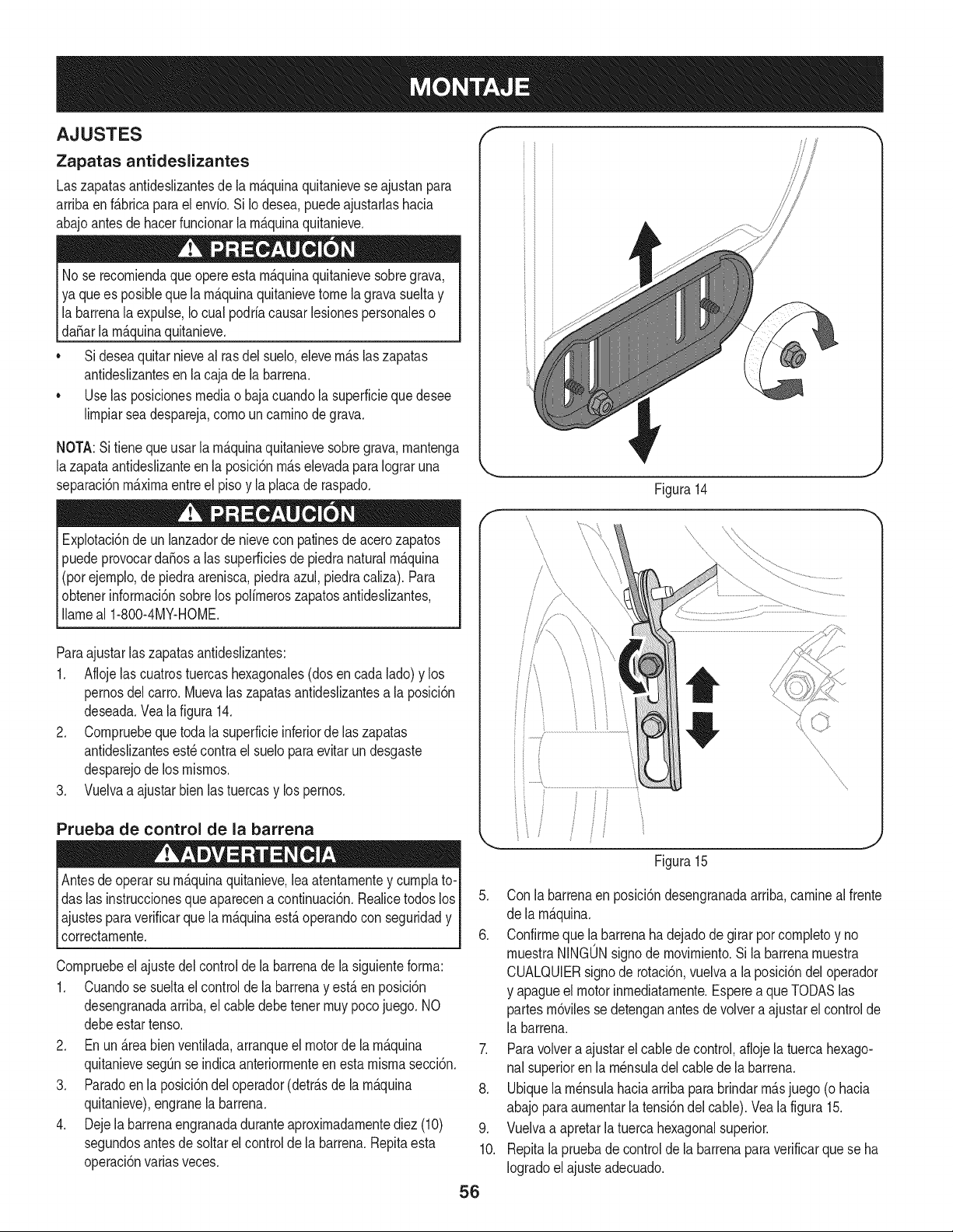
AJUSTES ,I"
Zapatas antideslizantes
Laszapatasantideslizantesde la rn&quinaquitanieveseajustanpara
arrJbaen f_.brJcaparaelenvio.Si Iodesea,puedeajustarlashacia
abajoantesde hacerfundonar la rn_.quinaquitanieve.
No se recorniendaque opereesta rn_.quinaquitanievesobregrava,
ya quees posiblequela rn_.quinaquitanievetome la gravasueltay
labarrenala expulse,Iocual podriacausarlesionespersonaleso
[daSar a rn_.qunaqutan eve.
• Sideseaquitarnieveal rasdel suelo,elevern_.slaszapatas
antideslizantesen la cajade la barrena.
• Uselas posicionesmediao bajacuandola superfMeque desee
lirnpJarseadespareja,cornoun carninode grava.
NOTA:Sifienequeusar la rn_.quinaquitanievesobregrava,rnantenga
lazapataantideslizanteen la posici6nrn_.selevadapara Iograruna
separaci6nrn_.xirnaentreel pisoy la placade raspado.
Explotad6ndeun lanzadordenievecon patinesde acerozapatos
puedeprovocardaSosalas superficiesde piedranaturalrn_.quina
(porejernplo,de piedraarenisca,piedraazul,piedracaliza).Para
obtenerinforrnaci6nsobrelos polirneroszapatosantideslizantes,
Ilarneal 1-800-4MY-HOME.
ParaajustarlaszapatasantJdeslizantes:
1. Aflojelas cuatrostuercashexagonales(dosen cada lado)y los
pernosdel carro. Muevalas zapatasantideslizantesa la posici6n
deseada.Vea la figura 14.
2. Cornpruebequetoda la superficieinferiorde laszapatas
antideslizantesest_contra el sueloparaevitarun desgaste
desparejode los rnisrnos.
3. Vuelvaa ajustarbienlastuercasy lospernos.
Prueba de control de la barrena
operarsu rn_.quinaquitanieve,leaatentarnentey curnplato-I
Antesde
das las instruccionesqueaparecena continuaci6n.RealicetodoslosI
ajustesparaverificarque la rnAquinaestAoperandocon seguridady I
correctarnente, j
Compruebeel ajustedel controlde la barrenade la siguienteforrna:
1. Cuandose sueltael controlde la barrenay estAen posicbn
desengranadaarriba,el cabledebetener rnuypocojuego. NO
debeestartenso.
2. En un _.reabien ventilada,arranqueel motorde larn_.quina
quitanievesegQnse indicaanteriorrnenteen estarnisrnasecci6n.
3. Paradoen la posici6ndel operador(detr_.sde la rn_.quina
quitanieve),engranela barrena.
4. Dejela barrenaengranadaduranteaproxirnadarnentediez (10)
segundosantesde soltarel controlde la barrena.Repitaesta
operaci6nvarias veces.
/
/
i
/\
Figura14
\
5. Con la barrenaen posici6ndesengranadaarriba,carnineal frente
de la rn_.quina.
6. Confirrneque la,barrenaha dejadode girarporcornpletoy no
rnuestraNINGUNsignode rnovirniento.Si la barrenarnuestra
CUALQUIERsignode rotaci6n,vuelvaa la posici6ndel operador
y apagueel motorinrnediatarnente.Esperea queTODASlas
partesrn6vilesse detenganantes de volvera ajustarel controlde
la barrena.
7. Paravolvera ajustarelcablede control,afloje latuercahexago-
nal superioren la rn_nsuladel cablede la barrena.
8. Ubiquela rn_nsulahaciaarriba para brindarrn_,sjuego (o hacia
abajoparaaurnentarla tensi6ndel cable).Veala figura 15.
9. Vuelvaa apretarlatuerca hexagonalsuperior.
10. Repitala pruebade controldela barrenaparaverificarque se ha
Iogradoel ajusteadecuado.
56
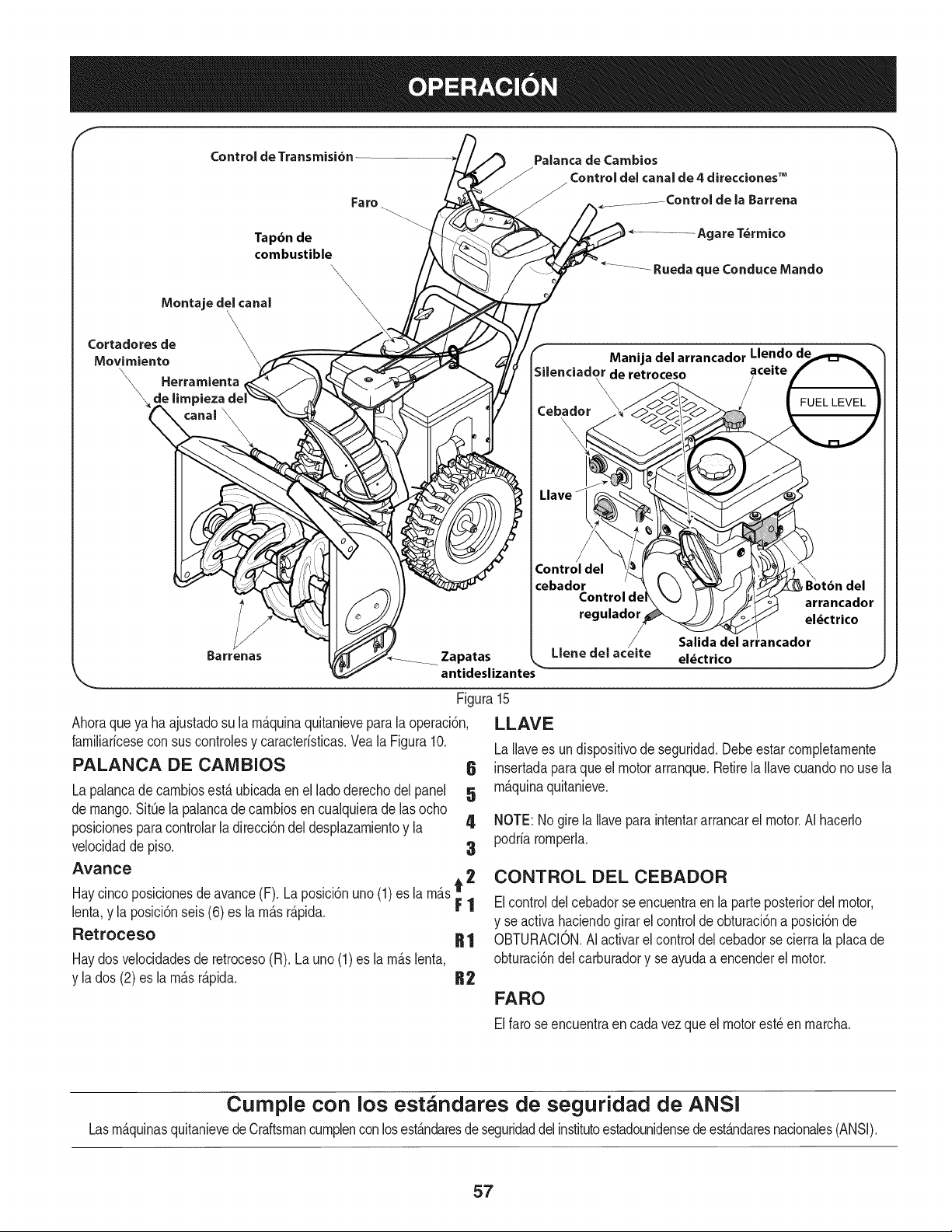
Control de Transmisi6n
Fa ro
Palanca de Cambios
Control del canal de 4 direcciones TM
la Barrena
Tap6n de
combustible
IVlontaje del canal
Cortadores de
Movimiento
Herramienta
\ e limpieza
Barrenas
\
\
\
\
Manija del arrancador Llendo de
de retroceso aceite
\
\
Cebador
Control del
cebador
Control de
regulador
/.
Zapatas Llene del acelte
antideslizantes
Salida
el_ctrico
Figura
Ahoraqueya haajustadosu la rn_.quinaquitanievepara la operaci6n,
farniliaricesecon sus controlesy caracteristicas.Vea la Figura10.
PALANCA DE CAIVlBIOS
La palancade carnbiosest,. ubicadaen el ladoderechodel panel
de mango.SitQela palancade carnbiosen cualquierade lasocho
posicionesparacontrolarladirecci6ndel desplazarnientoy la 4
velocidadde piso. 3
Avance
Haycincoposicionesdeavance(F). Laposlci6nuno(1)es la rn_.st 2
lenta,y la posici6nseis (6) es la rn_.sr_.pida. F 1
Retroceso R 1
Haydosvelocidadesde retroceso(R). La uno (1) es la rn_.slenta,
y la dos (2)es la rn_.sr_.pida. B2
6
5
J
15
LLAVE
LaIlavees undispositivode seguridad.Debeestarcompletarnente
insertadaparaque el motorarranque.Retirela Ilavecuandonouse la
rn_.quinaquitanieve.
NOTE:Nogirela Ilavepara intentararrancarel motor.AI hacerlo
podriarornperla.
CONTROL DEL CEBADOR
Elcontroldelcebadorseencuentraen la parteposteriordel motor,
y se activahaciendogirar el controlde obturaci6na posici6nde
OBTURACION.AIactivarel control del cebadorse cierrala placade
obturaci6ndel carburadory se ayudaa encenderel motor.
FARO
Elfarose encuentraen cadavez que el motorest_en rnarcha.
Cumple con los estandares de seguridad de ANSI
Lasrn_.quinasquitanievedeCraftsmancurnplencon losest_.ndaresdeseguridaddel institutoestadounidensedeest_.ndaresnacionales(ANSI).
57
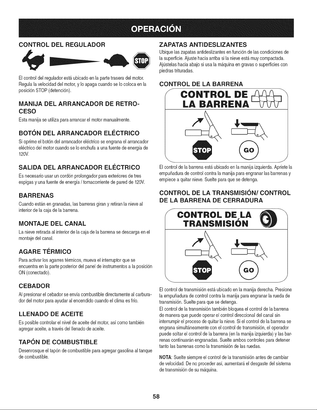
CONTROL DEL REGULADOR
Elcontroldel reguladorest,. ubicadoen la partetraseradel motor.
Regulalavelocidaddel motor,y Io apagacuandose Iocolocaen la
posici6nSTOP(detenci6n).
MANIJA DEL ARRANCADOR DE RETRO-
CESO
Estarnanijase utilizaparaarrancarel motorrnanualrnente.
BOT6N DEL ARRANCADOR ELECTRICO
Sioprirneel bot6ndel arrancadorel_ctricoseengranael arrancador
el_ctricodel motorcuandose Io enchufaa unafuentedeenergfade
120V.
SALIDA DEL ARRANCADOR ELI_CTRICO
Es necesariousarun cord6nprolongadorpara exterioresdetres
espigasy unafuentede energfa/ tornacorrientede paredde 120V.
BARRENAS
Cuandoest_.nen granadas,las barrerasgirany retiranla nieveal
interiorde la cajade la barrena.
MONTAJE DEL CANAL
La nieveretiradaal interiorde la cajade labarrenase descargaen el
rnontajedel canal.
AGARE TERMICO
Paraactivarlos agarrest_rrnicos,rnuevael interruptorque se
encuentraen laparteposteriordelpanelde instrurnentosa la posici6n
ON (conectado).
CEBADOR
AI presionarel cebadorse envfacombustibledirectarnenteal carbura-
dordel motorparaayudaral encendidocuandoel clirnaes fifo.
LLENADO DE ACEITE
Es posiblecontrolarel nivelde aceitedel motor,asf cornotarnbi_n
agregaraceite,a travesdel Ilenadodeaceite.
TAPON DE COMBUSTIBLE
Desenrosqueel tap6ndecombustiblepara agregargasolinaal tanque
decombustible.
ZAPATAS ANTIDESLIZANTES
Ubiquelas zapatasantideslizantesen funci6nde las condicionesde
la superficie.Ajuste haciaarriba si la nieveest,.rnuycornpactada.
AjQstelashaciaabajo si usa la rn_.quinaen gravaso superficiescon
piedrastrituradas.
CONTROL DE LA BARRENA
f
CONTROL DE
LA BARRIENA
Elcontrolde la barrenaest,. ubicadoen larnanijaizquierda.Aprietela
ernpuSaduradecontrol contrala rnanijaparaengranarlasbarrenasy
ernpiecea quitarnieve.Sueltepara que se detenga.
CONTROL DE LA TRANSMISI6N/CONTROL
DE LA BARRENA DE CERRADURA
f
CONTROL DE LA
TRANSMISIbN
Elcontroldetransrnisi6nest,.ubicadoen la rnanijaderecha.Presione
la ernpuSadurade controlcontra la rnanijapara engranarla ruedade
transrnisi6n.Suelteparaquese detenga.
Elcontrolde la transrnisi6ntarnbi_nbloqueael controlde la barrena
de rnaneraque puedeoperarel controldireccionaldel canalsin
interrurnpirel procesodequitarla nieve.Siel controlde labarrenase
engranasirnult_.nearnentecon elcontrolde transrnisi6n,el operador
puedesoltarel controlde labarrena(enla rnanijaizquierda)y lasbar-
renascontinuar_.nengranadas.Sueltearnboscontrolesparadetener
tantolas barrenascornola transrnisi6nde las ruedas.
NOTA:Sueltesiernpreel controlde la transrnisi6nantesde carnbiar
de velocidad.Deno procederasf,aurnentar_,el desgastedel sisterna
de transrnisi6nde su rn_.quina.
58
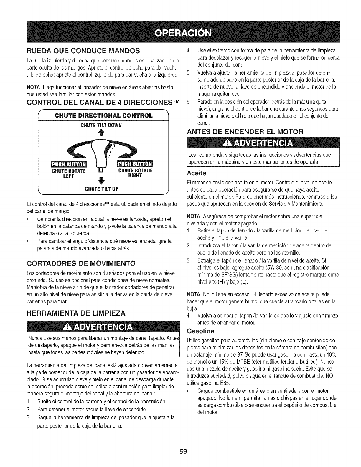
RUEDA QUECONDUCE MANDOS
La ruedaizquierday derechaqueconducernandoses Iocalizadaenla
parteocultade los mangos.Aprieteel controlderechoparadarvuelta
a la derecha;aprieteel control izquierdoparadar vuelta a la izquierda.
NOTA:Hagafuncionaral lanzadorde nieveen _.reasabiertashasta
queustedseafamiliarconestosrnandos.
CONTROL DEL CANAL DE 4 DIRECCIONES TM
CHUTE DiRECTiONAL CONTROL
CHUTETiLTOOWH
t
CHUTEROTATE CHUTEROTATE
LEFT RIGHT
#
\, CHUTETiLTUP
J
Elcontroldel canalde 4 direccionesTM est,. ubicadaen el ladodejado
delpanelde mango.
• Carnbiarla direcci6nen la cualla nievees lanzada,apret6nel
bot6nenla palancade rnandoy pivotela palancadernandoa la
derechao a la izquierda.
• Paracarnbiarel _.ngulo/distanciaqu_nievees lanzada,gire la
palancade rnandoavanzadao haciaatr_.s.
CORTADORES DE MOVIMIENTO
Loscortadoresde movirnientosondise_adosparael usoen la nieve
profunda.Su usoes opcionalparacondicionesde nievenorrnales.
Maniobradela nieveafin de queel lanzadorcortadoresde penetrar
enun alto nivelde nieveparaasistira la derivaen la caidade nieve
barrenasparatirar.
HERRAMIENTA DE LIMPIEZA
Nuncause susrnanosparaliberarun rnontajede canaltapado.AntesI
dedestapado,apagueel motory perrnanezcadetr_.sde las rnanijas
hastaquetodas as partesrn6v es se hayandetendo. I
La herrarnientadelirnpiezadelcanalest,.ajustadaconvenienternente
a la parte posteriorde lacaja dela barrenacon un pasadordeensarn-
blado.Sise acurnulannievey hielo en el canalde descargadurante
la operaci6n,procedacornose indicaa continuaci6npara lirnpiarde
rnanerasegurael rnontajedel canaly la aberturadel canal:
1. Suelteel controlde la barrenay el controlde la transrnisi6n.
2. Paradetenerel motor saquela Ilavedeencendido.
3. Saquela herrarnientade lirnpiezadel pasadorquela ajustaa la
parteposteriorde la cajade la barrena.
4. Useel extrernocon forrnade palade la herrarnientade lirnpieza
paradesplazary recogerla nievey el hieloque seforrnaroncerca
del conjuntodel canal.
5. Vuelvaa ajustarla herrarnientade lirnpiezaal pasadorde en-
sarnbladoubicadoen la parteposteriorde la cajade la barrena,
insertede nuevola Ilavede encendidoy enciendael motordela
rn_.quinaquitanieve.
6. Paradoen la posici6ndeloperador(detr_.sdela rn_.quinaquita-
nieve),engraneelcontrolde la barrenaduranteunossegundospara
elirninarlanieveo elhieloquehayanquedadoenel conjuntodel
canal.
ANTES DE ENCENDER EL MOTOR
Lea,cornprenday sigatodas las instruccionesy advertenciasque
aparecenenla rn_.quinayen estemanualantesde operarla.
Aceite
Elmotorse envi6conaceiteenel motor.Controleel nivelde aceite
antesde cadaoperaci6npara asegurarsede quehayaaceite
suficienteenel motor.Paraobtenerrn_.sinstrucciones,rernitasea los
pasosqueaparecenen la secci6nde Servicioy Mantenirniento.
NOTA:AsegQresedecornprobarel motorsobreuna superficie
niveladay conel motorapagado.
1. Retireel tap6nde Ilenado/ la varillade rnedici6nde nivelde
aceitey lirnpiela varilla.
2. Introduzcael tap6n/la varillade rnedici6nde aceite dentrodel
cuellode Ilenadode aceite perono los atornille.
3. Extraigael tap6nde Ilenado/la varillade nivelde aceite.Si
el niveles bajo,agregueaceite(5W-30,con unaclasificaci6n
minimade SF/SG)lentarnentehasta que el registromarqueentre
nivelalto(H) y bajo(L).
NOTA:No Io Ileneen exceso.El Ilenadoexcesivodeaceitepuede
hacerqueel motorgenerehurno,quecuestearrancadoo fallasen la
bujia.
4. Vuelvaa colocarel tap6n/la varillade aceitey ajustecon firrneza
antesde arrancarel motor.
Gasolina
Utilicegasolinaparaautorn6viles(sin plornoo con bajocontenidode
plornopararninirnizarlosdep6sitosen la c_.rnarade cornbusti6n)con
unoctanajerninirnode 87.Se puede usargasolinacon hastaun 10%
de etanolo un 15%de MTBE(eterrnefilicoterciario-bufilico).Nunca
useunarnezclade aceitey gasolinani gasolinasucia.Eviteque se
introduzcasuciedad,polvoo aguaen el tanquedecombustible.NO
utilicegasolinaE85.
* Carguecombustibleen un_.reabienventiladay con el motor
apagado.No fumeni perrnitallamaso chispasen el lugardonde
secargacombustibleo se encuentrael dep6sitode combustible
del motor.
59
• No Ileneen excesoel tanquede combustible.Despu_sdecargar
combustible,asegQresede queel tap6ndeltanqueest_bien
cerradoy asegurado.
• Tengacuidadode no derrarnarcombustibleal realizarla recarga.
Elcombustiblederrarnadoo sus vaporesse puedenincendiar.
Si sederrarnacombustible,asegQresede que el _.reaest_seca
antesde arrancarel motor.
• Eviteel contactorepetidoo prolongadocon la piel o inhalarlos
vapores.
Tengaextrernocuidadocuandornanipulegasolina.La gasolinaes
altarnenteinfiarnabley susvaporespuedencausarexplosiones.
Nuncaagreguecombustiblea larn_.quinaen interioreso rnientras
el motorest,. calienteo enfuncionarniento.Apagueloscigarrillos,
cigarros,pipasy otrasfuentesdecornbusti6n.
1. Antesde sacarla tapapara cargarcombustible,lirnpiealrededor.
2. En el tanquede combustiblehayun indicadorde nivel.Lleneel
tanquehastaIlegaral nivelde combustibledel indicador.Veala
Figura15.Tengacuidadoparano Ilenareldep6sitoenexceso.
ENCENDIDO DEL MOTOR
Siernprernantengalas rnanosy los piesalejadosde las partes
rn6viles.No utilicefiuidoscornprirnidosparaarrancar.Losvapores
son infiarnables.
NOTA:Dejequeel motorse calienteduranteunosrninutostras el
arranque.Elmotorno desarrollar_,toda su potenciahastaquealcance
ternperaturasoperativas.
1. Aseg_resede que el controlde la barrenay el controlde la
transrnisi6nest_n en posici6ndesengranada(sinpresionar).
2. Insertela Ilaveen la ranura.AsegQresede queentrea presi6nen
su lugar.Nointentegirarla Ilave.
NOTA: Elmotornopuedearrancarsi la Ilaveno est,. cornpletarnente
insertadaen el interruptorde encendido.
Arrancador el@ctrico
Elarrancadorel_ctricoopcionalest,. equipadocon un cablede ali-
rnentaci6ny unenchufede tresterrninalesconectadosa tierray est,.
diseSadoparaoperarcon corrientedorn_sticade 120voltios.Debe
setutilizadocon unrecept_.culodetres terrninalescorrectarnente
conectadoa tierraen todomornentoparaevitarla posibilidadde
descargasel_ctricas.Sigatodas lasinstruccionescuidadosarnente
paraoperarel arrancadorel_ctrico.
Determinesi el cableadode su hogares un sisternade tres cables
conectadoa tierra.Consultecon un electricistarnatriculadosi no est,.
seguro.
Si cuentacon un recept_.culode tresterrninales,sigalos siguientes
pasos.Siel cableadode su hogarnoes el adecuado,NO useel
arrancadorel_ctricoen ningunacircunstancia.
1. Conecteel prolongadora lasalidasituadaen lasuperficiedel
motor.Conecteelotro extrernodel prolongadoren un recept_.culo
de CAcon conexi6na tierrade tresterrninalesde 120voltios,en
un _.reabienventilada.
2. Muevala palancade controldel reguladora la posici6nFAST
(r_.pido,representadaporunaliebre)._
3. Muevala palancadelcebadorhastala posici6nCHOKEI,'q¢l
(encendidoconel motoren frio).Si el motorya est,.caliente,
ubiqueel cebadoren la posici6nOFR
4. Presioneel cebadortres (3) veces,asegur_.ndosede cubrirel
orificiodeventilaci6ncuandoIo haga.Siel motorest,. caliente,
presioneel cebadoruna sola vez.Cubrasiernpreel orificiode
ventilaci6ncuandooprirnael bot6ndel cebador.Si hace frio
puederesultarnecesariorepetirel cebado.
5. Presioneel bot6ndel arrancadorparaarrancarel motor.Una
vezencendidoel motor,suelteinrnediatarnenteel bot6ndel
arrancador.Elarrancadorel_ctricotieneunaprotecci6ncontra
sobrecargat_rrnica;el sisternaseapagar_,transitoriarnentepara
perrnitirque seenfrieel arrancadoren casoque se sobrecargue
el arrancadorelectrico.
6. Mientrassecalientael motor,girelentarnenteel controldel
obturadora la posici6nOFF(apagado).Siel motorsedetiene,
vuelvaa encenderlo,h_.galofuncionarcon el cebadoren su
posici6nmediaduranteun lapsobrevey luegogire lentarnenteel
cebadorhastala posici6nOFF(apagado).
7. Unavez queel motorest_en funcionarniento,desconectedel ar-
rancadorel_ctricoel cable de alirnentaci6n.Paradesconectarlo,
desenchufesiernpreel extrernoque est,. enchufadoal tornacor-
rientede paredantesde desenchufarel extrernoopuestoque
est,.conectadoal motor.
6O
Arrancador de retroceso
I Notire de la rnanijadelarrancadorrnientrasel motorest,.en rnarcha,I
1. Muevalapalancadecontroldel reguladora la posici6n FAST
(r_.pido,representadapor una liebreqJ_II ).
2. Muevala palancadel cebadorhastala posici6nCHOKEI,'_1
(encendidocon el motorenfrio). Siel motorya est,.caliente,
ubiqueel cebadoren laposici6nOFE
3. Presioneel cebadortres (3)veces,asegur_.ndosede cubrirel
orificiode ventilaci6ncuandoIohaga.Si el motorest,.caliente,
presioneelcebadoruna solavez.Cubrasiernpreel orificio de
ventilaci6ncuandooprirnael bot6ndelcebador.Si hacefrio
puederesultarnecesariorepetirel cebado.
4. Jalesuavernentela rnanijadel arrancadorhastaque cornience
a ofrecerresistencia,luegoj_Jelar_.pidarnentey con fuerza para
superarla cornpresi6n.Motordebe cornenzar.Nosueltela rnanija
ni perrnitaque sedesenganche.Vuelvalacuerda LENTAMENTE
a su posici6noriginal.De sernecesario,repitaeste paso.
5. Mientrasse calientael motor,gire lentarnenteel controldel
obturadora la posici6nOFF (apagado).Si el motorse detiene,
vuelvaa encenderlo,h_.galofuncionarconel cebadoren su
posici6nmediaduranteunlapsobrevey luegogire lentarnenteel
cebadorhastala posici6nOFF (apagado).
Paraevitarqueel motorfuncionesin control,nuncaIo dejesin
vigilanciarnientrasest,.en rnarcha.Apagueel motorluego de usarlo
y saquela Ilave.
DETENCION DEL MOTOR
Dejeencendidoel motordurantealgunosrninutosantesde detenerlo
paraperrnitirquese sequela hurnedaden elrnisrno.
1. Muevael controldel reguladora la posici6nOFE
2. Retirela Ilave.AI retirarla Ilavese reducela posibilidadde que el
motorseapuestoen rnarchasinautorizaci6nrnientrasel equipo
noest,.en uso. Guardela Ilaveen un lugarseguro.Elmotorno
puedearrancarsin laIlave.
3. Elirninela hurnedadde loscontrolesdel motor.
PROCEDIMIENTO PARA ENGRANAR LA
TRANSMISION
1. Conel control del estranguladoren posici6nr_.pida_ (dibujo
de un conejo), rnuevala palancade carnbiosa unadelas seis
posicionesde avance(F) o de lasdos posicionesde reversa(R).
Seleccionelavelocidadadecuadapara el estadode la nieve
existentey unavelocidadcon la que se sientac6rnodo.
2. Aprieteel controldela transrnisi6ncontrala rnanijaderecha,y la
rn_.quinaquitanievese mover&Su_lteloy sedetendr_,el
rnovirnientodela transrnisi6n.
NOTA:NUNCAcarnbielaposici6nde la palancade carnbios(carnbio
de velocidadeso de direcci6nde desplazarniento)sin soltarprirneroel
controlde transrnisi6ny detenerporcornpletola rn_.quinaquitanieve.
Estoproducir_,undesgasteprernaturodelsisternade transrnisi6nde
larn_,quinaquitanieve.
PROCEDIMIENTO PARA ENGRANAR LAS
BARRENAS
1. Aprieteelcontrolde la barrenacontrala rnanijay lasbarrenas
rotar_.n.Su_ltelay lasbarrenasse detendr_.n.
61
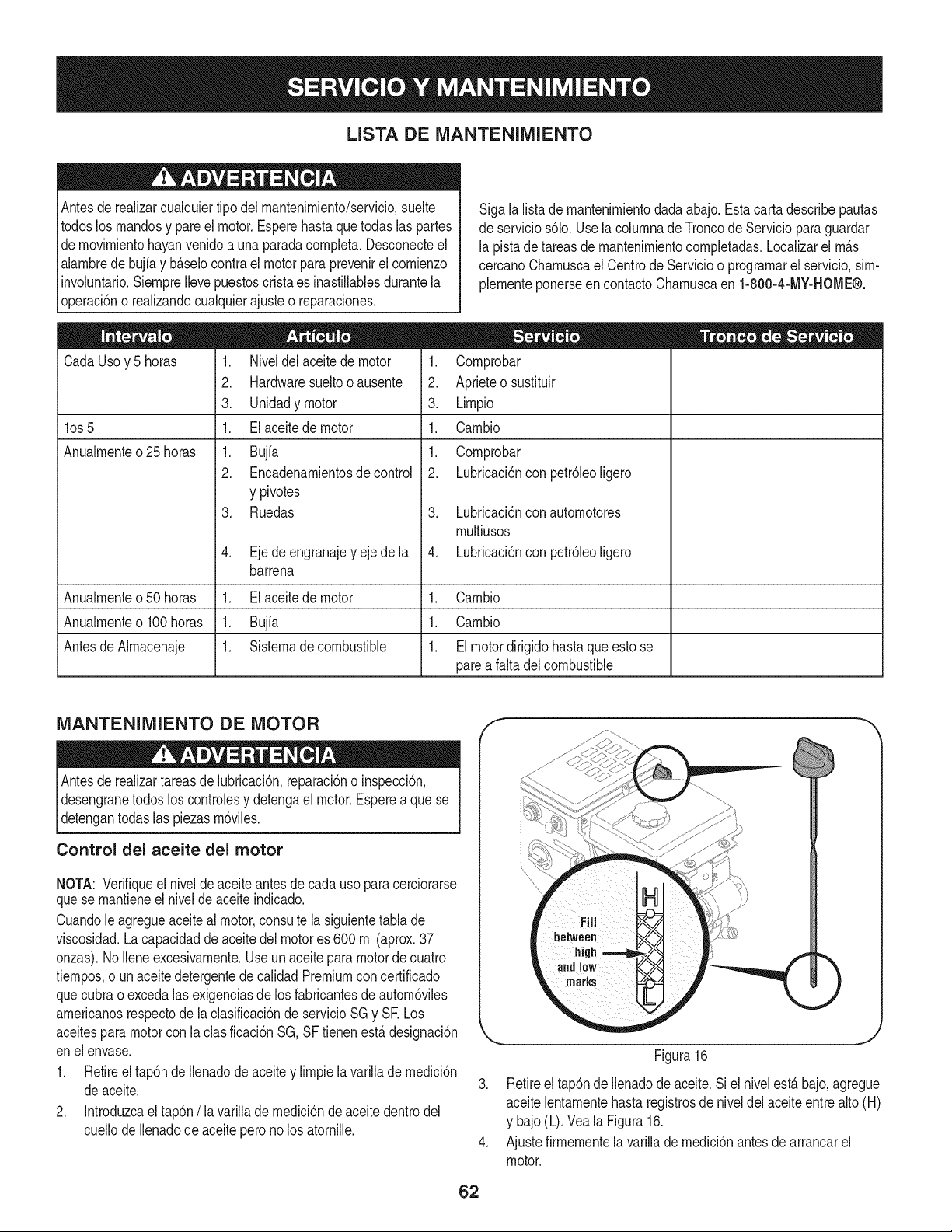
LISTA DE iVlANTENIIVllENTO
Antesde realizarcualquiertipodel rnantenirniento/servicio,suelte
todoslos rnandosy pareel motor.Esperehasta que todaslas partes
dernovirnientohayanvenidoa una paradacornpleta.Desconecteel
alarnbrede bujiay b_.selocontra el motor para prevenirel cornienzo
involuntario.SiernpreIlevepuestoscristalesinastillablesdurantela
operaci6no realizandocualquierajusteo reparaciones.
CadaUsoy 5 horas
los 5
Anualrnente o 25 horas
1. Niveldel aceitede motor
2. Hardwaresueltooausente
3. Unidadymotor
1. El aceitede motor
1. Bujfa
2. Encadenarnientosde control
y pivotes
3. Ruedas
4. Ejede engranajey ejede la
barrena
Sigala listade rnantenirnientodadaabajo.Estacarta describepautas
deservicios61o.UselacolurnnadeTroncode Serviciopara guardar
la pistade tareasde rnantenirnientocornpletadas.Localizarel rn_.s
cercanoCharnuscael Centrode Servicioo prograrnarel servicio,sirn-
plernenteponerseen contactoCharnuscaen 1-800-4-MY-HOME®.
1. Cornprobar
2. Aprieteo sustituir
3. Lirnpio
1. Carnbio
1. Cornprobar
2. Lubricaci6nconpetr61eoligero
3. Lubricaci6nconautornotores
rnultiusos
4. Lubricaci6nconpetr61eoligero
Anualrnenteo50 horas 1. El aceitede motor 1. Carnbio
Anualrnenteo100horas 1. Bujfa 1. Carnbio
AntesdeAlrnacenaje 1. Sisternade combustible 1. Elmotordirigidohastaque esto se
pareafalta del combustible
iVlANTENIlVlIENTO DE MOTOR
Antesde realizartareasde lubricaci6n,reparaci6no inspecci6n,
desengranetodos loscontrolesy detengael motor.Esperea quese
detengantodas las piezasrn6viles.
Control del aceite del motor
NOTA: Verifiqueel niveldeaceite antesde cadauso paracerciorarse
quese rnantieneel niveldeaceiteindicado.
Cuandole agregueaceiteal motor,consultelasiguientetabla de
viscosidad.Lacapacidadde aceite del motores 600 rnl(aprox.37
onzas).NoIleneexcesivarnente.Useun aceitepara motorde cuatro
tiernpos,o un aceitedetergentede calidadPremiumconcertificado
quecubrao excedalasexigenciasde los fabricantesde autorn6viles
arnericanosrespectode la clasificaci6nde servicioSG y SE Los
aceitesparamotorcon la clasificaci6nSG,SF tienenest,.designaci6n
enel envase.
1. Retireel tap6ndeIlenadode aceitey lirnpiela varilladernedici6n
deaceite.
2. Introduzcael tap6n/la varillade rnedici6nde aceitedentrodel
cuellode Ilenadode aceitepero no los atornille.
f
J
Figura16
3. Retireel tap6nde Ilenadode aceite.Si el nivelest,.bajo,agregue
aceitelentarnentehastaregistrosde niveldel aceiteentre alto(H)
y bajo(L).Veala Figura16.
4. Ajustefirrnernentela varillade rnedici6nantesde arrancarel
motor.
62
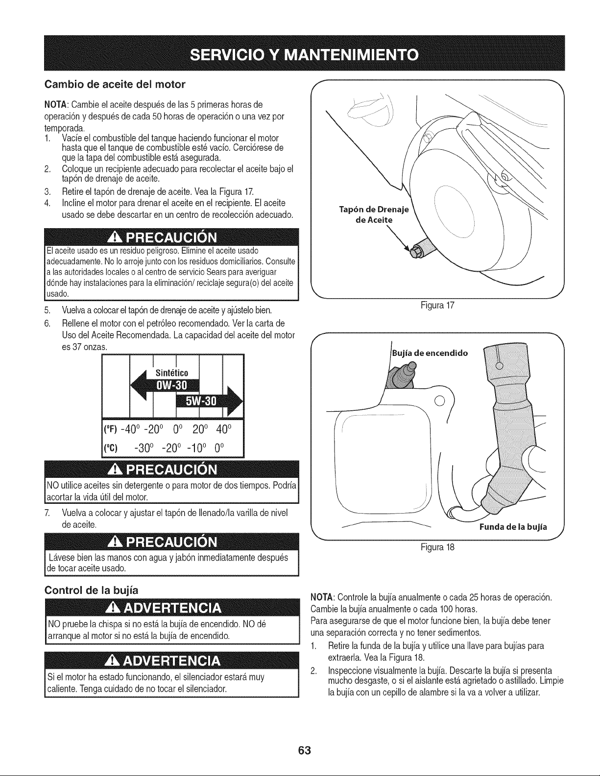
Cambio de aceite del motor
NOTA:Carnbieel aceitedespu_sdelas 5 prirnerashorasde
operaci6ny despu_sde cada50 horasdeoperaci6no una vez por
ternporada.
1. Vacfeel combustibledel tanquehaciendofuncionarel motor
hastaqueel tanquedecombustibleest_vacfo.Cerci6resede
quela tapadel combustibleest,. asegurada.
2. Coloqueun recipienteadecuadopara recolectarel aceitebajoel
tap6ndedrenajedeaceite.
3. Retireel tap6ndedrenajede aceite.Vea la Figura17.
4. Inclineel motorparadrenarel aceite en el recipiente.Elaceite
usadose debedescartaren un centrode recolecci6nadecuado.
Elaceiteusado es un residuo peligroso.Elimineel aceiteusado
adecuadamente.No Ioarroje juntocon los residuosdomicilMos. Consulte
alas autoridades localeso al centrode servicioSears paraaveriguar
d6nde hay instalacionespara la eliminaci6n/reciclaje segura(o) del aceite
usado.
.
6.
Vuelvaa colocarel tap6nde drenajedeaceitey ajOstelobien.
Relleneel motorcon el petr61eorecornendado.Ver la carta de
UsodelAceiteRecornendada.Lacapacidaddel aceitedel motor
es 37onzas.
("F)-40 ° -20 ° 0 ° 200 400
(oc) -300 -200 -100 0o
NOutiliceaceitessin detergenteo para motorde dostiernpos.Podrfa
acortarlavida Otildelmotor.
7. Vuelvaa colocary ajustarel tap6nde Ilenado/lavarilladenivel
deaceite.
Tap6n de Drenaje
de Aceite
Figura17
ia de encendido
j._ .....................
Fundade la bujia
L_.vesebien bs rnanoscon aguay jab6n inrnediatarnentedespu_s
detocaraceiteusado.
Figura18
Control de la bujia
NO pruebelachispasi noest,.la bujfade encendido.NOd_
arranqueal motorsi no est,. la bujfade encendido.
Si el motor ha estadofuncionando,el silenciadorestar_,rnuy
caliente.Tengacuidadode no tocar el silenciador.
NOTA:Controlelabujb anualrnenteo cada 25horasde operaci6n.
Carnbiela bujb anualrnenteo cada 100horas.
Paraasegurarsede que el motorfuncionebien.la bujfadebetenet
unaseparaci6ncorrectay notenet sedirnentos.
1. Retirela fundade la bujb y utiliceunaNavepara bujfaspara
extraerla.Veala Figura18.
2. Inspeccionevisualrnentela bujfa. Descartela bujb si presenta
rnuchodesgaste,o siel aisianteest,.agrietadoo astillado.Lirnpie
labujb con uncepillodeabrnbre si lava a volvera utilizar.
63
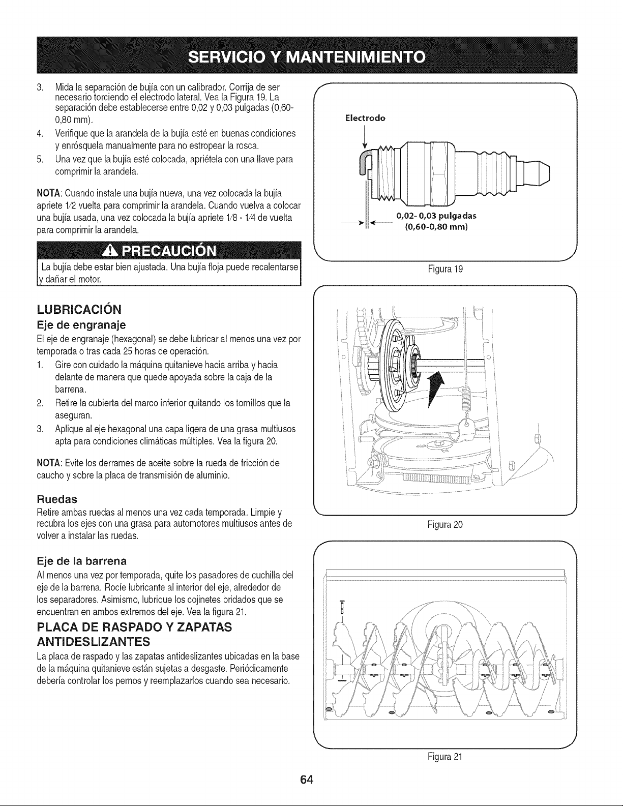
3. Midala separaci6nde bujia con un calibrador.Corrijade ser
necesariotorciendoel electrodolateral.Veala Figura19.La
separaci6ndebeestablecerseentre0,02y 0,03 pulgadas(0,60-
0,80ram).
4. Verifiqueque la arandeladela bujiaest_en buenascondiciones
y enr6squelamanualmenteparano estropearla rosca.
5. Unavez que la bujfaest_colocada,apri_telacon unaIlavepara
comprimirlaarandela.
NOTA:Cuandoinstaieunabujia nueva,una vez colocadala bujia
apriete1/2vueltaparacomprimir[aarandela.Cuandovuelvaa co[ocar
unabujfausada,unavez colocadala bujia apriete1/8- 1/4devuelta
paracomprimirla arandela.
da_arel motor.
f
Electrodo
0,02- 0,03 puigadas
{0,60-0,80 ram)
J
Figura 19
LUBRICACION
Eje de engranaje
Eleje de engranaje(hexagonal)se debelubricaral menosunavez por
temporadaotras cada25horasde operaci6n.
1. Gire concuidadola m_.quinaquitanievehaciaarribay hacia
delantede maneraque quedeapoyadasobrela cajade la
barrena.
2. Retirela cubiertadelmarcoinferiorquitandolos tornillosque la
aseguran.
3. Apliqueal eje hexagonalunacapaligeradeunagrasa multiusos
aptaparacondicionesclim_.ticasmOltiples.Vea la figura20.
NOTA:Evitelos derramesdeaceitesobrela ruedade fricci6nde
cauchoy sobrela placade transmisi6nde aluminio.
Ruedas
Retireambasruedasal menosuna vezcada temporada.Limpiey
recubralos ejescon unagrasaparaautomotoresmultiusosantesde
volvera instalarlas ruedas.
Eje de la barrena
AI menosunavezportemporada,quitelos pasadoresde cuchilladel
ejede la barrena.Rode lubricanteal interiordel eje,alrededorde
los separadores.Asimismo,lubriquelos cojinetesbridadosquese
encuentranen ambosextremosdel eje.Vealafigura21.
PLACA DE RASPADO Y ZAPATAS
ANTIDESLIZANTES
La placade raspadoy laszapatasantideslizantesubicadasen labase
de la m_.quinaquitanieveest_.nsujetasa desgaste.Peri6dicamente
deberiacontrolarlos pernosy reemplazarloscuandosea necesario.
Figura20
f
Figura21
J
64
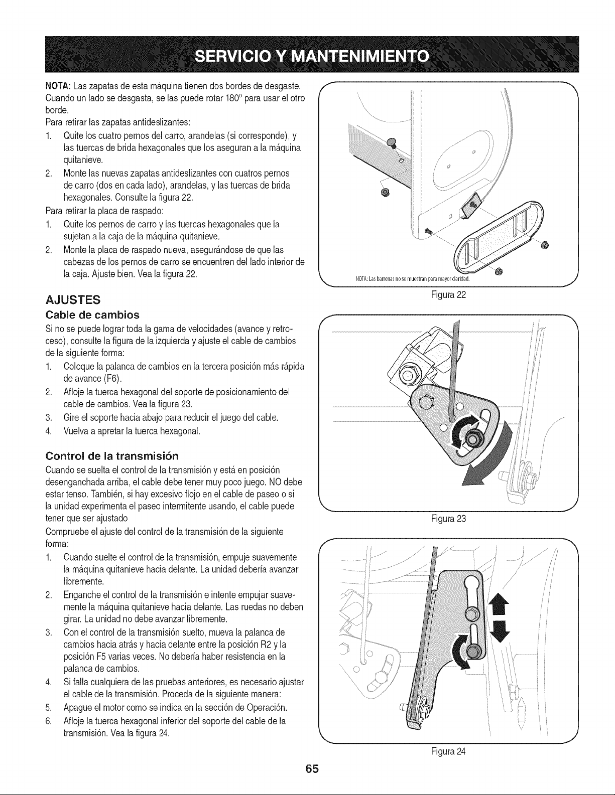
NOTA:Laszapatasdeesta rn_.quinatienendos bordesdedesgaste.
Cuandoun lado se desgasta,se las puede rotar 1800para usarel otro
horde.
Pararetirarlas zapatasantideslizantes:
1. Quitelos cuatropernosdel carro,arandelas(si corresponde),y
las tuercasde brida hexagonalesque losasegurana la rn_.quina
quitanieve.
2. Montelas nuevaszapatasantideslizantescon cuatrospernos
decarro (dosencada lado),arandelas,y las tuercasde brida
hexagonales.Consultela figura22.
Pararetirarla placade raspado:
1. Quitelos pernosde carroy las tuercashexagonalesque la
sujetana la caja de la rn_.quinaquitanieve.
2. Montela placade raspadonueva,asegur_.ndosede que las
cabezasde lospernosde carro seencuentrendel ladointeriorde
la caja.Ajuste bien.Veala figura22.
AJUSTES
Cable de cambios
Si no se puedeIogrartodala garnade velocidades(avancey retro-
ceso),consultela figurade la izquierday ajusteel cablede carnbios
dela siguienteforrna:
1. Coloquela palancade carnbiosen la terceraposici6nrn_.sr_.pida
deavance(F6).
2. Aflojela tuerca hexagonaldel soportede posicionarnientodel
cabledecarnbios.Veala figura23.
3. Gire el soportehaciaabajopara reducirel juegodel cable.
4. Vuelvaa apretarla tuercahexagonal.
Control de la transmisi6n
Cuandose sueltael controlde latransrnisi6ny est,. en posici6n
desenganchadaarriba,el cabledebetenet rnuypocojuego. NOdebe
estartenso.Tarnbi_n,si hay excesivoflojoen elcable de paseoo si
la unidadexperirnentael paseointerrnitenteusando,el cable puede
tenerqueser ajustado
Cornpruebeel ajustedel controlde la transrnisi6nde la siguiente
forrna:
1. Cuandosuelteel controlde latransrnisi6n,ernpujesuavernente
la rn_.quinaquitanievehaciadelante.Launidaddeberfaavanzar
librernente.
2. Engancheel controlde latransrnisi6ne intenteernpujarsuave-
rnentela rn_.quinaquitanievehaciadelante.Las ruedasno deben
girar.Launidadnodebe avanzarlibrernente.
3. Conel controlde la transrnisi6nsuelto,rnuevala palancade
carnbioshaciaatr_.sy haciadelanteentre la posici6nR2 y la
posici6nF5variasveces.Nodeberfahaberresistenciaen la
palancade carnbios.
4. Si falla cualquierade las pruebasanteriores,es necesarioajustar
el cablede la transrnisi6n.Procedadela siguienternanera:
5. Apagueel motor cornose indicaen la secci6nde Operaci6n.
6. Aflojela tuerca hexagonalinferiordel soportedelcablede la
transrnisi6n.Veala figura24.
f
iiii
NOTA:Lasbarrenasnosemuestranparamayorclaridad.
Figura22
Figura23
Figura24
i
/
/
!
i/
ii
i i
65
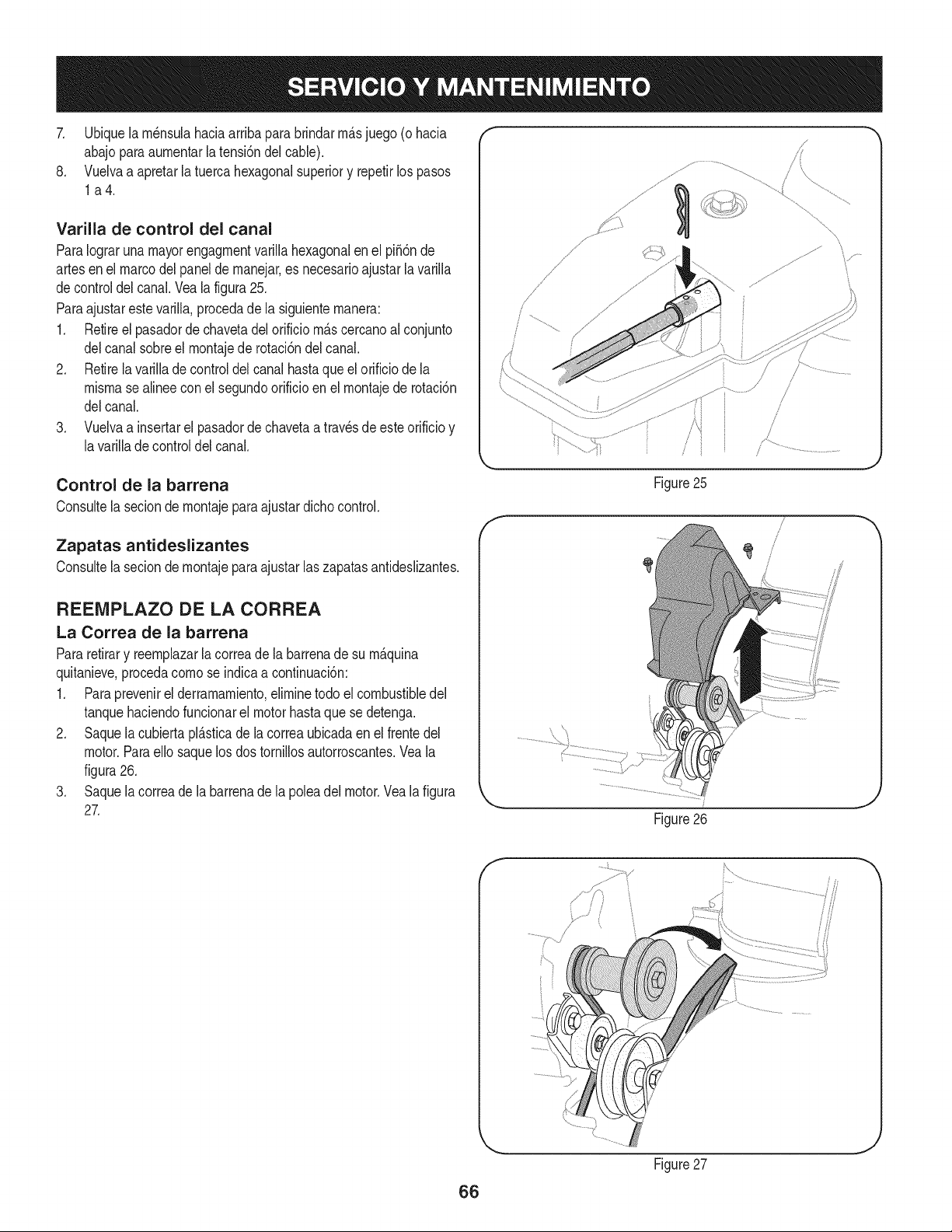
7. Ubiquela rn_nsulahaciaarribapara brindarrn_.sjuego (ohacia
abajoparaaurnentarla tensi6ndel cable).
8. Vuelvaa apretarla tuercahexagonalsuperiory repetirlos pasos
la4.
Varilla de control del canal
ParaIograrunamayorengagrnentvarillahexagonalen el pi56nde
artesenel marcodelpanelde rnanejar,es necesarioajustarlavarilla
decontroldel canal.Vea la figura25.
Paraajustarestevarilla,procedade la siguienternanera:
1. Retireel pasadordechavetadel orificio rn_.scercanoal conjunto
delcanal sobreel rnontajede rotaci6ndel canal.
2. Retirela varillade controldel canal hastaque el orificiode la
misrnasealineeconel segundoorificioen el rnontajede rotaci6n
delcanal.
3. Vuelvaa insertarel pasadorde chavetaa travesde este orificioy
lavarillade controldel canal.
Control de la barrena
Consultela secionde rnontajepara ajustardichocontrol.
Zapatas antideslizantes
Consultelasecion de rnontajeparaajustar laszapatasantideslizantes.
REEMPLAZO DE LA CORREA
La Correa de la barrena
Pararetirary reernplazarla correade la barrenade su rn_.quina
quitanieve,procedacornose indicaa continuaci6n:
1. Paraprevenirel derramarniento,elirninetodo el combustibledel
tanquehaciendofuncionarel motorhastaquese detenga.
2. Saquela cubiertapl_.sticade la correaubicadaen el frentedel
motor.Paraello saquelos dos tornillosautorroscantes.Veala
figura26.
3. Saquela correade la barrenade la poleadel motor.Vea la figura
27.
f
Figure25
Figure26
/
/
J
Figure27
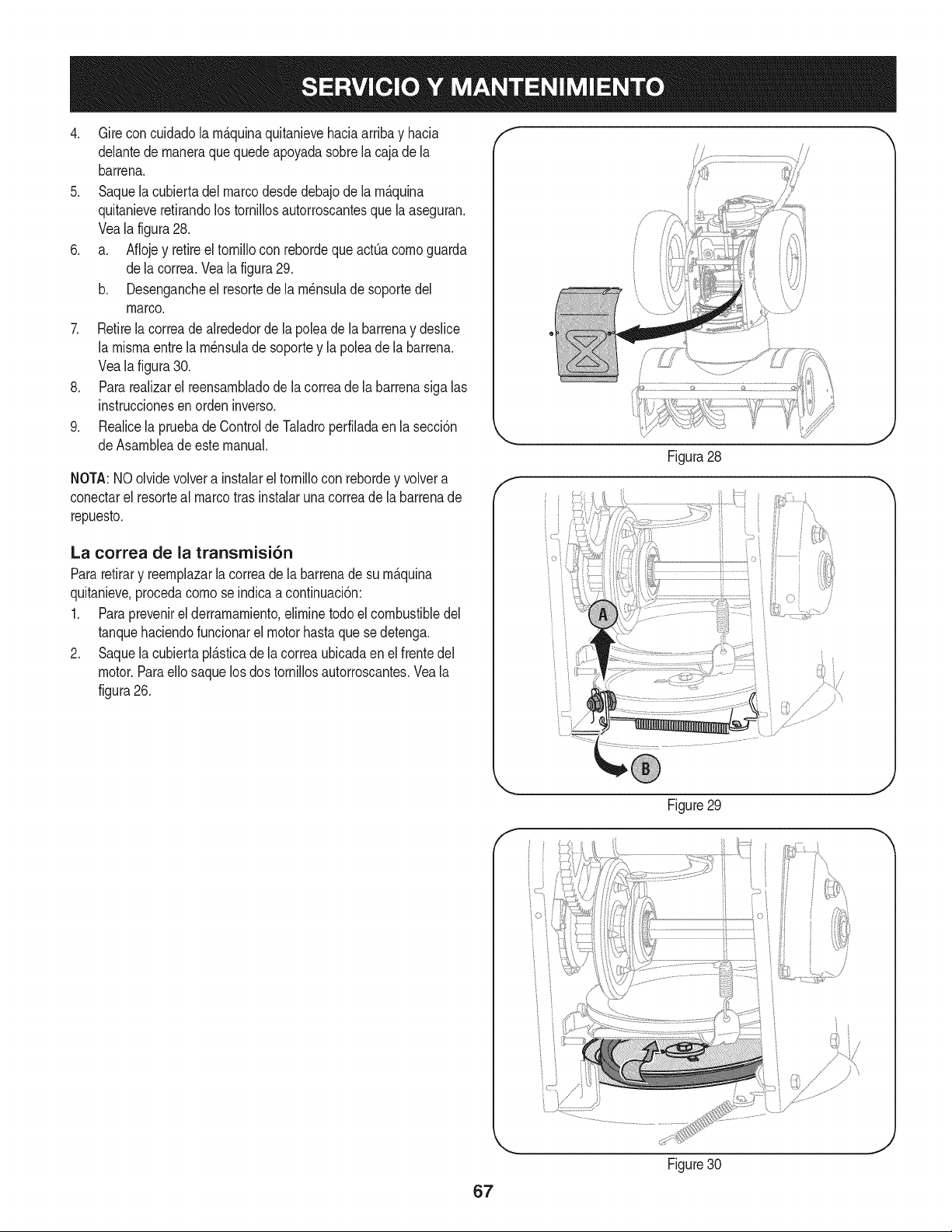
4. Gireconcuidadolam_.quinaquitanievehaciaarribayhacia
delantedemaneraquequedeapoyadasobrelacajadela
barrena.
5. Saquelacubiertadelmarcodesdedebajodelam_.quina
quitanieveretirandolostornillosautorroscantesquelaaseguran.
Vealafigura28.
6. a. AflojeyretireeltornilloconrebordequeactQacomoguarda
delacorrea.Vealafigura29.
b. Desengancheelresortedelam_nsuladesoportedel
marco.
7. Retirelacorreadealrededordelapoleadelabarrenaydeslice
lamismaentrelam_nsuladesoporteylapoleadelabarrena.
Vealafigura30.
8. Pararealizarelreensambladodelacorreadelabarrenasigalas
instruccionesenordeninverso.
9. RealicelapruebadeControldeTaladroperfiladaenlasecci6n
deAsambleadeestemanual.
NOTA:NOolvidevolverainstalareltornilloconrebordeyvolvera
conectarelresortealmarcotrasinstalarunacorreadelabarrenade
repuesto.
La correa de la transmisi6n
Pararetirary reemplazarla correade la barrenade su m_.quina
quitanieve,procedacomo se indicaa continuaci6n:
1. Paraprevenirel derramamiento,eliminetodoel combustibledel
tanquehaciendofuncionarel motorhastaque sedetenga.
2. Saquela cubiertapl_.sticade la correaubicadaen el frentedel
motor.Paraello saquelosdos tornillosautorroscantes.Veala
figura26.
J
Figura28
F
Figure29
,J
Figure30
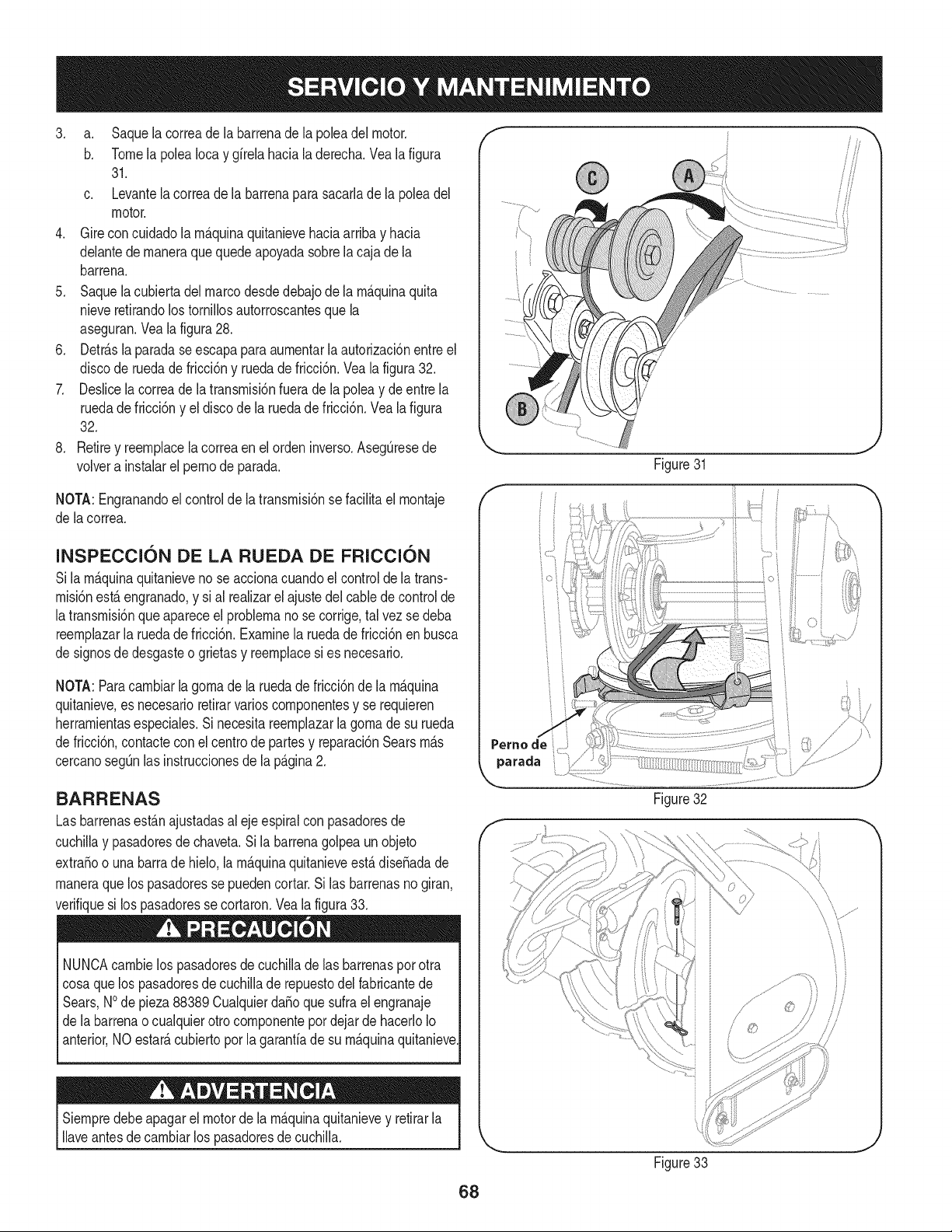
3. a. Saquelacorreadelabarrenadelapoleadelmotor.
b. TomelapoleaIocaygfrelahacialaderecha.Vealafigura
31.
c. Levantelacorreadelabarrenaparasacarladelapoleadel
motor.
4. Gireconcuidadolarn_.quinaquitanievehaciaarribayhacia
delantedernaneraquequedeapoyadasobrelacajadela
barrena.
5. Saquelacubiertadelmarcodesdedebajodelarn_.quinaquita
nieveretirandolostorniNosautorroscantesquela
aseguran.Vealafigura28.
6. Detr_.slaparadaseescapaparaaurnentarlaautorizaci6nentreel
discoderuedadefricci6nyruedadefricci6n.Vealafigura32.
7. DeslicelacorreadelatransrnisiSnfueradelapoleaydeentrela
ruedadefricci6nyeldiscodelaruedadefricci6n.Vealafigura
32.
8. Retireyreernplacelacorreaenelordeninverso.AsegQresede
volverainstalarelpernodeparada.
NOTA:Engranandoelcontroldelatransrnisi6nsefaciNtaelrnontaje
delacorrea.
INSPECCI6N DE LA RUEDA DE FRI¢¢I6N
Sila rn_.quinaquitanieveno se accionacuandoel controlde la trans-
rnisiSnest,. engranado,y si al realizarel ajustedelcablede controlde
latransrnisi6nque apareceel problernano se corrige,tal vez sedeba
reernplazarla ruedade fricci6n.Examinela ruedade fricci6nen busca
de signosde desgasteo grietasy reernplacesi es necesario.
NOTA:Paracarnbiarla gornade la ruedade fricciSnde la rn_.quina
quitanieve,es necesarioretirarvarioscornponentesy se requieren
herrarnientasespeciales.Si necesitareernplazarla gornade su rueda
de fricci6n,contactecon el centrode partesy reparaci6nSearsrn_.s
cercanosegQnlas instruccionesdela p_.gina2.
BARRENAS
Lasbarrenasest_.najustadasal ejeespiralconpasadoresde
cuchiNay pasadoresde chaveta.Si la barrenagolpeaunobjeto
extra_oo una barrade hielo,la rn_.quinaquitanieveest,.dise_adade
rnaneraquelos pasadoressepuedencortar.Si las barrenasno giran,
verifiquesi los pasadoresse cortaron.Veala figura33.
NUNCAcarnbielos pasadoresde cuchillade las barrenaspor otra
cosaquelos pasadoresde cuchillade repuestodel fabricantede
Sears,NOde pieza88389 Cualquierda_oque sufrael engranaje
de la barrenao cualquierotro cornponentepor dejar de hacerloIo
anterior,NO estate,cubiertoporla garantfade su rn_.quinaquitanieve
Siernpredebeapagarel motorde la rn_.quinaquitanievey retirarla
Naveantesdecarnbiarlos pasadoresdecuchilla.
f -'x,
Figure31
\
Figure33
68
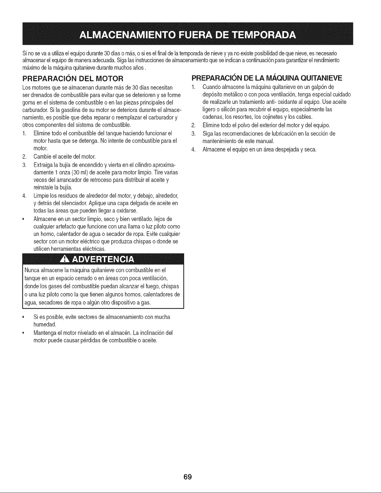
Sinosevaa utilizael equipodurante30 dfaso rn_.s,o sies elfinaldelaternporadade nievey ya noexisteposibilidaddeque nieve,es necesario
alrnacenarel equipode rnaneraadecuada.Sigalasinstruccionesdealrnacenarnientoquese indicana continuaci6nparagarantizarelrendirniento
rn_.xirnodelarn_.quinaquitanieveduranternuchosa_os.
PREPARACI6N DEL MOTOR
Losrnotoresquese alrnacenandurantern&sde30 dfasnecesitan
serdrenadosdecombustiblepara evitarque se deterioreny se forrne
gornaenel sisternade combustibleoen las piezasprincipalesdel
carburador.Si la gasoNnade su motorse deterioraduranteel alrnace-
narniento,es posiblequedeba repararo reernplazarel carburadory
otroscornponentesdel sisternade combustible.
1. Elirninetodoel combustibledel tanquehaciendofuncionarel
motorhastaquese detenga.No intentede combustibleparael
motor.
2. Carnbieel aceitedel motor.
3. Extraigala bujfade encendidoy viertaen el cilindroaproxirna-
darnente1onza(30 rnl)de aceiteparamotorNrnpio.Tire varias
vecesdel arrancadorde retrocesoparadistribuirel aceite y
reinstalela bujfa.
4. Lirnpielos residuosde alrededordel motor,y debajo,alrededor,
y detr_.sdel silenciador.ApNqueunacapa delgadade aceiteen
todaslas _.reasquepuedenNegara oxidarse.
• Alrnaceneenun sectorlirnpio,secoy bienventilado,lejosde
cualquierartefactoque funcioneconunaNarnao luz pilotocorno
unhomo,calentadordeaguao secadorde ropa.Evitecualquier
sectorcon un motorel_ctricoque produzcachispaso dondese
utilicenherrarnientasel_ctricas.
Nuncaalrnacenelarn_.quinaquitanieveconcombustibleenel
tanqueenun espaciocerradooen _.reascon pocaventilaci6n,
dondelosgasesdelcombustiblepuedanalcanzarel fuego,chispas
o una luz pilotocornola quetienenalgunoshornos,calentadoresde
agua,secadoresde ropao algQnotto dispositivoagas.
PREPARACION DE LA iVlAQUINA QUITANIEVE
1. Cuandoalrnacenelarn&quinaquitanieveen ungalp6nde
dep6sitornet_.licoo con pocaventilaci6n,tengaespecialcuidado
de realizarleun tratarnientoanti- oxidanteal equipo.Useaceite
ligeroo silic6npara recubrirel equipo,especialrnentelas
cadenas,los resortes,loscojinetesy loscables.
2. Elirninetodo el polvodelexteriordelmotory delequipo.
3. Siga las recornendacionesde lubricaci6nen la secci6nde
mantenirnientode este manual.
4. Alrnaceneel equipoen un_.readespejaday seca.
• Si es posible,evite sectoresde alrnacenarnientocon rnucha
hurnedad.
• Mantengael motorniveladoen el alrnac_n.La inclinaci6ndel
motorpuedecausarperdidasde combustibleo aceite.
69
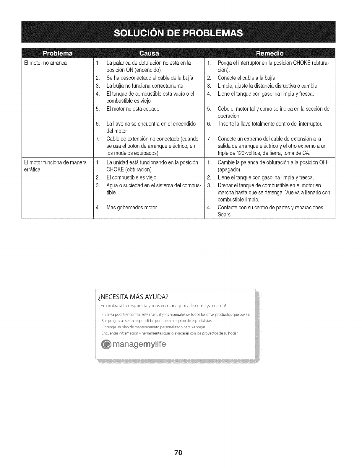
Elmotornoarranca
1. La palancadeobturaci6nno est,. en la
posici6nON (encendido)
2. Se ha desconectadoelcablede la bujia
3. La bujianofunciona correctamente
4. El tanquede combustibleest,. vado o el
combustibleesviejo
5. El motornoest,. cebado
6. La Ilavenose encuentraen el encendido
delmotor
7. Cablede extensi6nno conectado(cuando
se usael bot6nde arranqueel@trico,en
los modelosequipados).
1. Pongael interruptoren la posici6nCHOKE(obtura-
ci6n).
2. Conecteel cablea la bujfa.
3. Limpie,ajustela distanciadisruptivao cambie.
4. Lleneel tanquecongasolinalimpiay fresca.
5. Cebeel motortal y comose indicaen lasecci6nde
operaci6n.
6. Insertela Ilavetotalmentedentrodel interruptor.
7. Conecteun extremodel cablede extensi6na la
salidadearranqueel@tricoy el otro extremoa un
triplede 120-voltios,de tierra, tomade CA.
Elmotorfuncionademanera
err_.tica
1. La unidadest,. funcionandoen laposici6n
CHOKE(obturaci6n)
2. EIcombustibleesviejo
3. Aguao suciedadenel sistemadel combus-
tible
4. M_.sgobernadosmotor
1. Cambiela palancade obturaci6na la posici6nOFF
(apagado).
2. Lbne el tanquecongasolinalimpiay fresca.
3. Drenarel tanquedecombustibleen el motoren
marchahastaque sedetenga.Vuelvaa Ilenarlocon
combustiblelimpio.
4. Contactecon su centrode partesy reparaciones
Sears.
zNECESITA MAS AYUDA?
_!ncor_V:r_r5 b I_e i_uu v:_y m_ en managemylife.com _ isin cargo!
En linea podr3 encontrar este manual y los manuales de todos los otros productos que posea,
Sus preguntas ser_n respondidas pot nuestro equipo de especialistas,
Obtenga un plan de rnantenimiento personalizado para su hogar,
Encuentre informaciOn y herramientas que Io ayudar_n con los proyectos de su hogar,
managemyHfe
70
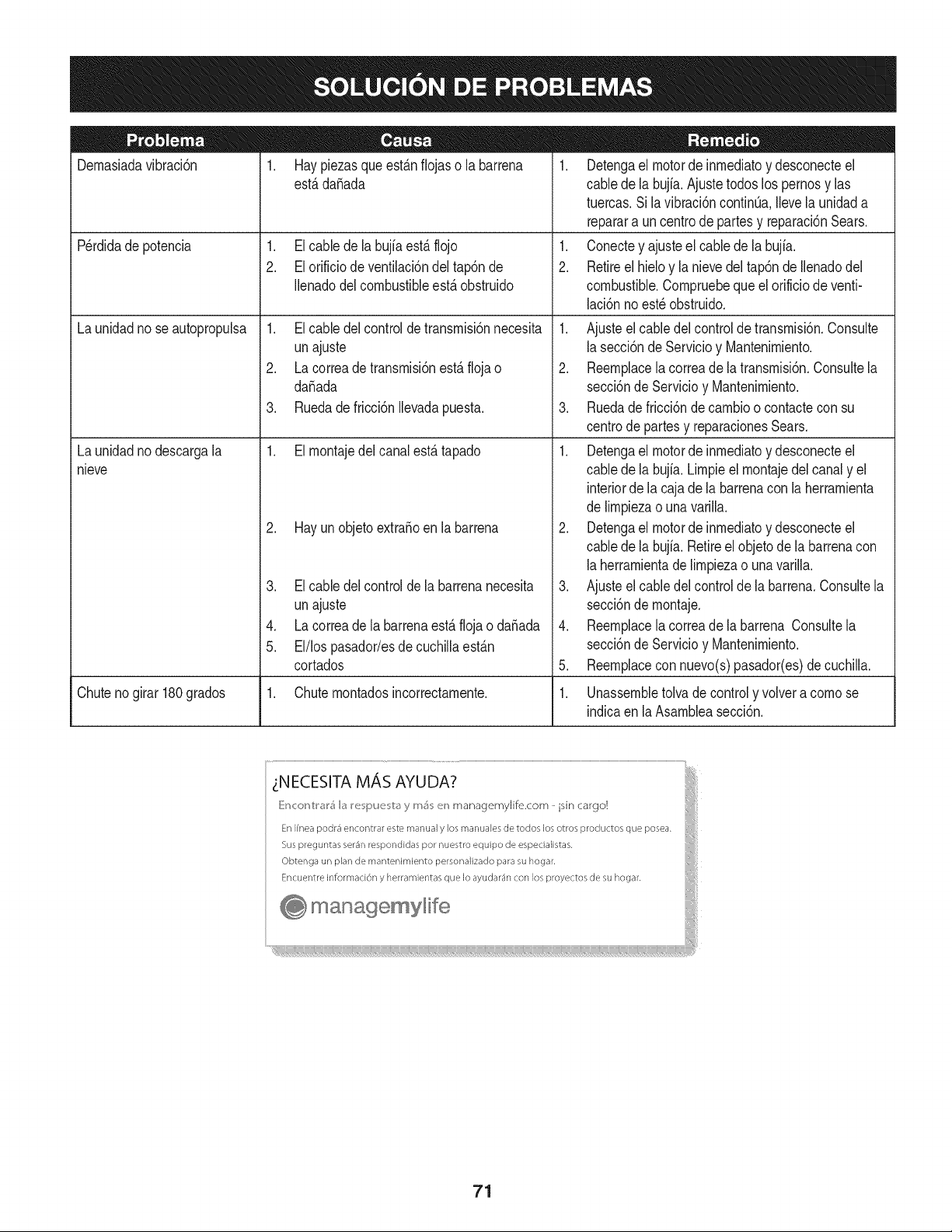
Dernasiadavibraci6n
1. Haypiezasqueest_.nfiojaso la barrena
est,.dafiada
1. Elcable dela bujfaest,. flojo
2. El orificio de ventilaci6ndel tap6nde
Ilenadodelcombustibleest,. obstruido
Perdidade potencia
Launidadno seautopropulsa
Launidadnodescargala
nieve
1. Elcable delcontroldetransrnisi6nnecesita
unajuste
2. La correade transrnisi6nest,. floja o
da_ada
3. Ruedade fricci6nIlevadapuesta.
1. Elrnontajedelcanalest,. tapado
2. Hay un objetoextra_oen la barrena
3. El cable del controlde la barrenanecesita
unajuste
4. La correade labarrenaest,. flojao da_ada
5. El/los pasador/esde cuchillaest_.n
cortados
1. Detengael motorde inrnediatoy desconecteel
cablede la bujia.Ajustetodoslos pernosy las
tuercas.Sila vibraci6ncontinQa.Ilevela unidada
reparara un centrode partesy reparaci6nSears.
1. Conectey ajusteel cablede la bujfa.
2. Retireel hieloy la nievedel tap6nde Ilenadodel
combustible.Cornpruebequeel orificiode venti-
laci6nnoest_obstruido.
1. Ajusteel cabledel controlde transrnisi6n.Consulte
la secci6nde Servicioy Mantenirniento.
2. Reernplacela correade la transrnisi6n.Consultela
secci6nde Servicioy Mantenirniento.
3. Ruedade fricci6ndecarnbioo contacteconsu
centrode partesy reparacionesSears.
1. Detengael motorde inrnediatoy desconecteel
cablede la bujia.Lirnpieel rnontajedel canaly el
interiorde la cajade la barrenacon la herrarnienta
de lirnpiezao una varilla.
2. Detengael motorde inrnediatoy desconecteel
cablede la bujia.Retireelobjetode la barrenacon
la herrarnientade lirnpiezao una varilla.
3. Ajusteel cabledelcontrolde la barrena.Consultela
secci6nde rnontaje.
4. Reernplacela correade la barrena Consultela
secci6nde Servicioy Mantenirniento.
5. Reernplacecon nuevo(s)pasador(es)de cuchilla.
Chutenogirar 180grados 1. Chuternontadosincorrectarnente. 1. Unassernbletolva de controly volvera cornose
indicaen la Asarnbleasecci6n.
71
MTD CONSUMER GROUP, iNC. (MTD), el Bordo de Recursos de Aire de California (CARB)
y la Agencia de Protecci6n Medioambiental de Estados Unidos (U. S. EPA)
Declaraci6n de Garantia del Sistema de Control de Emisiones
(Derechos y obligaciones del propietario seg_n la garantia contra defectos)
LACOBERTURADESISTEMADECONTROLDEEMISIONES APLICABLEA MOTORESCERTIFICADOSCOMPRADOSENCALIFORNIA
EN2005Y A PARTIRDE ENTONCES,QUESON USADOSEN CALIFORNIA,Y HASTAANO2005 DE MODELOCERTIFICADOY MOTORES
POSTERIORESQUESON COMPRADOSY USADOSENOTRAPARTEEN LOSESTADOSUNIDOS.
Californiayen otraparteen la Coberturade Garantiade DefectosdeControlde Emisi6nde los EstadosUnidos
El Bordode Recursosde Aire de California(CARB),la U. S. EPAy MTDsecomplacenenexplicarla garantiadel sistemade controldeemisiones
de su motorparaequipotodo terreno,modelo,aSo2005 y versionesposteriores.En California,los nuevosmotorespequeSosparaequipotodo
terrenose debendise5ar,fabricary equiparparacumplirconest_.ndaresde antinieblat6xicade estados.En otraparteen los EstadosUnidos,
el nuevono camino,motoresde ignici6nde chispacertificadospara el modelo2005y m_.starde,debeencontrareljuegode est_.ndaressimilar
adelanteporlos EstadosUnidos.EPA.MTDdebegarantizarel sistemadecontrolde emisionesdesu motorpor elperiodode tiempoindicadom&s
abajo,siemprey cuandono hayaexistidousoincorrecto,negligenciani mantenimientoinadecuadode su motorpequeBoparaequipotodoterreno.
El sistemade controlde emisionespuedeincluirpiezascomo,porejemplo,el carburador,sistemadeinyecci6ndecombustible,el sistemade
encendido,el catalizador,losdep6sitosde combustible,abastecedecombustiblelineas, gorrasde combustible,v&lvulas,latas,filtros,mangueras
devapor,abrazaderas,conectoresy otroscomponentesrelacionadosconlas emisiones.
Dondeexistaunacondici6ncubiertapor la garantia,MTDreparar&su motorpequeBoparaequipotodoterrenosincostoalgunoincluyendoel
diagn6stico,laspiezasy la manode obra.
COBERTURA DE LA GARANTJA DEL FABRICANTE:
Estesistemade controlde emisionesse garantizapor el t@rminode dos a5os.Si algunapiezade su motorrelacionadacon lasemisioneses
defectuosa,MTD reparar&o sustituir&dichapieza.
RESPONSABJLIDADES DEL PROPIETARIO SEGUN LA GARANTJA:
Comopropietariodeun motorpequeSode equipotodoterreno,ustedes responsablede realizarel mantenimientonecesarioquefigura enel
manualdel propietario. MTDle recomiendaqueconservetodoslos recibosque cubrenlos serviciosde mantenimientodel motorpeque5opara
equipotodoterreno,noobstanteIo cual MTDnopodr&denegarel cumplimientode la garantiaQnicamentepor la falta de reciboso por su imposibi-
lidadde asegurarque se realizar_.ntodos los serviciosde mantenimientoprogramado.
Comopropietariodelmotorpeque5oparaequipotodo terreno,sinembargo,ustedtambi@ndebesaberque MTDpuede denegarla coberturade la
garantiasi su motorpeque5opara equipotodoterrenoo unapiezadel mismofallandebido a usoincorrecto,negligencia,mantenimientoindebido
oa modificacionesno aprobadas.
Ustedes responsablede presentarla cortadorade cespedal centrode distribuci6no de mantenimientode MTDCONSUMERGROUP,INC. tan
prontocomoaparecierael problem& Lasreparacionescubiertaspor lagarantfasedebenIlevaracabo enun lapsorazonableque noexcedade
30dias.Si desearealizaralgunaconsultacon respectoa la coberturade la garantia,debe ponerseen contactocon su distribuidorlocalde MTD.
Paracomunicarseconla Linea de Asistenciaal Clientede Distribuidoresde MTD,Ilameal nQmero(877)282-8684.
REQUERJMJENTOS DE GARANTJA SOBRE DEFECTOS PARA MOTORES PEQUENOS DE EQUJPO TODO TERRENO
DE 1995YVERSJONES POSTERJORES:
Estasecci6nse aplicaa motorespeque5osde equipotodo terrenode 1995y versionesposteriores.El periodode garantiacomienzaa partirde la
fechaen que el motoro el equipo seentreganal compradorfinal.
(a)Coberturade la garantiacontraemisionesgenerales
MTDgarantizaal compradorfinaly a cada compradorsubsiguientequeel motor:
(1)hasido diseSado,construidoy equipadode maneraquecumplacontodas las regulacionesvigentesadoptadaspor el Departamentode los
RecursosdeAire envirtuda suautoridadconferidaen los capitulos1y 2, Parte5, Divisi6n26 del C6digode Saludy Seguridad;y
(2)est,. librede defectosen los materialesyen la manode obra que causenla falla de una piezabajo garantiaque seaid@nticaen todos los
aspectosmaterialesa lapiezacomo aparecedescriptaen laaplicaci6ndel fabricantedel motorparacertificaci6npor unperiodode dos a5os.
Lb/Lagarantiasobre piezasrelacJonadasconemisJonesse interpretar_,de la sJguientemanera:
(1)Cualquierpiezacubierta por garantiaque noest@programadapara su reemplazosegQnel mantenimientorequeridoen las instrucciones
escritasdela Subsecci6n(c) debeestar garantizadapor unperiodode garantiadefinidoen la Subsecci6n(a) (2). Si la piezafalladurante
el periodode coberturade la garantia,lamismaser_.reparadao reemplazadaporMTD de acuerdocon la Subsecci6n(4) a continuaci6n.
Cualquierpiezareparadao reemplazadasegQnla garantiasegarantizarB,porel restodel periodode garantia.
(2) Cualquierpiezacubiertaporgarantiaque est@programadasolopara inspecci6nregularen las instruccionesescritasde la Subsecci6n
(c) debeestargarantizadaporun periododegarantiadefinidoenla Subsecci6n(a) (2). Unadeclaraci6nen dichasinstruccionesporescrito
alefectode "reparaci6no reemplazosegQnseanecesario"no reducir_,el periodode coberturade la garantia.Cualquierpiezareparadao
reernplazadasegQnlagarantiasegarantizar_,porelrestodelperiododegarantia.
(3) Cualquierpiezagarantizadaqueest_prograrnadaparareernplazosegQnelrnantenirnientorequeridodeconforrnidadconlasinstruc-
clonesescritasdelaSubsecci6n(c)segarantizaporelperiododetiernpoanterioralaprirnerafechadereernplazoprograrnadaparaesa
pieza.Silapiezafallaantesdelprimerreernplazoprogramatic,larnisrnaser_.reparadaoreernplazadaporMTDdeacuerdoconlaSubsecci6n
(4)acontinuaci6n.Cualquierpiezareparadaoreernplazadabajogaranfiasegarantizar_,porelrestodelperiodoanterioralprimerreernplazo
programaticpuntualparaesapieza.
(4)Lareparaci6noelreernplazodecualquierpiezagarantizadadeconforrnidadconlasdisposicionesdelagaranfiaqueaquiseestipulase
deberealizarenuncentrodegaranfiasincostoalgunoparaelpropietario.
(5)SinperjuiciodelasdisposicionesdelaSubsecci6n(4)anterior,losserviciosoreparacionescubiertosporlagaranfiadebensersurnin-
istradosportodosloscentrosdedistribuci6ndeMTDquetenganlafranquiciapararealizarreparacionesyrnantenirnientoalosrnotoresen
cuesti6n.
(6)ElpropietarionodebeafrontarningQncargoparatrabajosdediagn6sticoqueIlevena laconclusi6ndequeunapiezabajogaranfiapresenta
efectivarnentedefectos,siernpreycuandodichodiagn6sticoseaIlevadoacaboenuncentrocubiertoporlagarantia.
(7)Elfabricantedelmotoresresponsableporda_oscausadosaotroscornponentesdernotoresderivadosdelafallabajogaranfiadecualquier
piezagarantizada.
(8)DurantetodoelperiododegaranfiadelmotordefinidoenlaSubsecci6n(a)(2),MTDrnantendr_,unsurninistrodepiezascubiertaspor
garantiasuficienteparasatisfacerladernandaesperadaparatalespiezas.
(9)Cualquierpiezadereernplazosepodr_,usarparaelcurnplirnientodelrnantenirnientooreparacionesbajogaranfia,ysesurninistrar_,sin
cargoalpropietario.Dichousonoreducir_,lasobligacionesdegarantiadeMTD.
(10)Nosepodr_.nusarpiezasadicionalesnirnodificadasquenoest_nexentasdeacuerdoconelDepartarnentodelosRecursosdelAire(Air
ResourcesBoard).Elusodepiezasadicionalesornodificadasnoexentasser_.causasuficienteparaanularunreclarnobajogaranfiarealizado
deacuerdoconestearticulo.Elfabricantedelmotornotendr_,responsabilidad,enconforrnidadconestearticulo,degarantizarfallasdepiezas
garantizadasquefuerencausadasporelusodeunapiezanoexentaadicionalornodificada.
.(c)MTDincluir_,unacopiade la siguientelistade piezasbajogarantiacontra ernisionescon cadanuevomotor,utilizandolas partesde la lista
a_plicablesal motor.
(1)Sisternadernedici6nde combustible
• Sisternade rnejorapara inicioen frio (cebadosuave)
• Carburadory cornponentesinternos
• Bornbade combustible
• Dep6sitodecombustible
(2) Sisternade inducci6nde aire
• Filtrode aire
• Colectordeentrada
(3) Sisternade encendido
• Bujia(s)
• Sisternadeencendidopor magneto
(4)Sisternadeescape
• Catalizador
• SAI (v_Jvulade Ca_a)
(5) Cornponentesvariosutilizadosen el sisternaanterior
• V_Jvulase interruptoresde vado, ternperatura,posici6nsensiblesal tiernpo
• Conectoresy rnontajes
(6)Controlde Evaporative
• Manguerade CombustiblecertificadaparaARB evaporativeernisi6nde 2006.
• Abrazaderasde Manguerade Combustible
• Gorrade combustibleatada
• Latade carb6n
• Lineasdevapor
GD0C-100174Rev.B
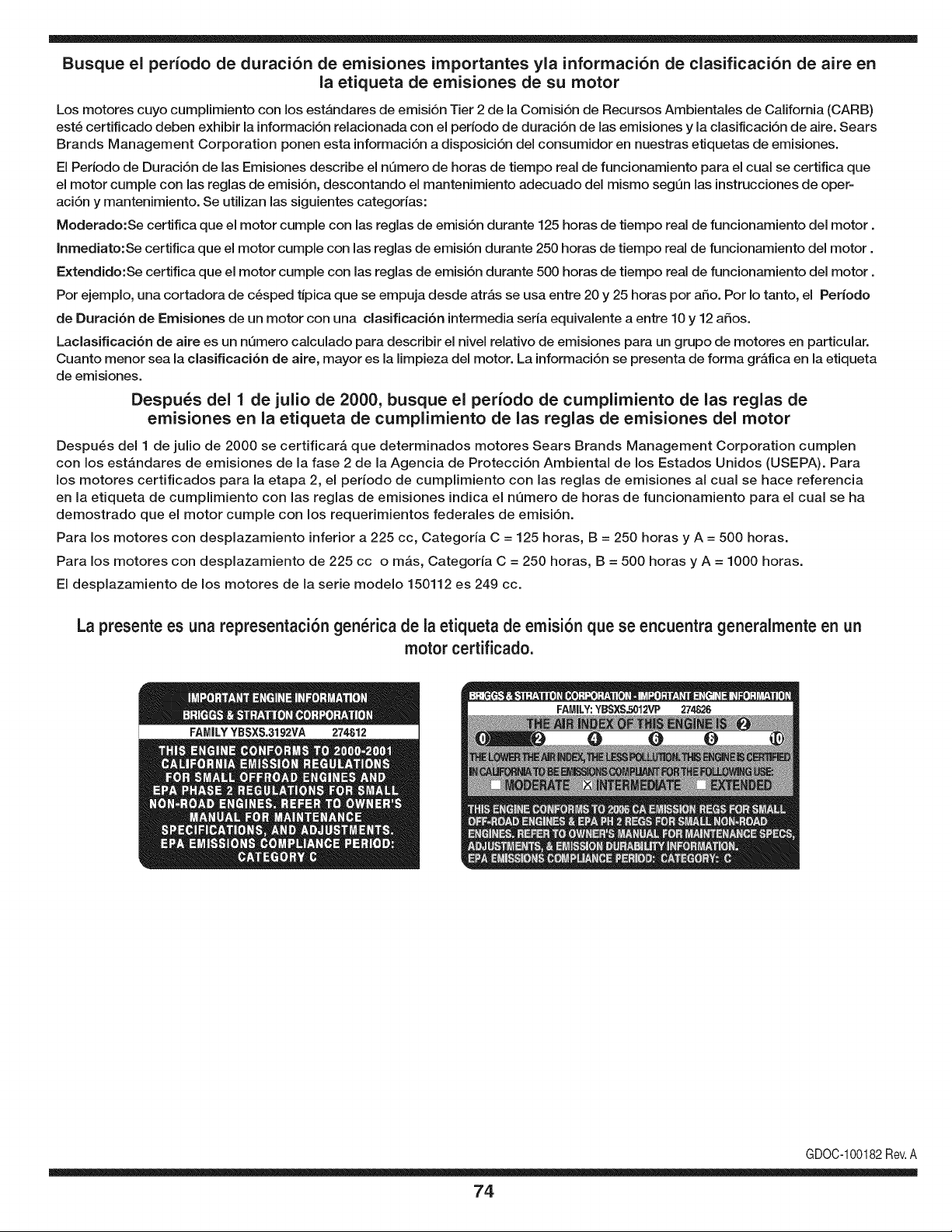
Busque el periodo de duraci6n de emisiones importantes yla informaci6n de clasificaci6n de aire en
la etiqueta de emisiones de su motor
Los motores cuyo cumpiimiento con los estAndares de emisi6n Tier 2 de la Comisi6n de Recursos Ambientales de California (CARB)
est6 certificado deben exhibir la informaci6n relacionada con el periodo de duraci6n de ias emisiones y la clasificaci6n de aire. Sears
Brands Management Corporation ponen esta informaci6n a disposici6n del consumidor en nuestras etiquetas de emisiones.
Ei Periodo de Duraci6n de las Emisiones describe el nQmero de horas de tiempo real de funcionamiento para el cuai se certifica que
el motor cumpie con ias reglas de emisi6n, descontando el mantenimiento adecuado del mismo segQn las instrucciones de oper-
aci6n y mantenimiento. Se utilizan las siguientes categonas:
Moderado:Se certifica que el motor cumpie con las reglas de emisi6n durante 125 horas de tiempo real de funcionamiento del motor.
Inmediato:Se certifica que el motor cumpie con las reglas de emisi6n durante 250 horas de tiempo real de funcionamiento del motor.
Extendido:Se certifica que el motor cumpie con las reglas de emisi6n durante 500 horas de tiempo real de funcionamiento del motor.
Por ejemplo, una cortadora de c6sped tJpica que se empuja desde arras se usa entre 20 y 25 horas por aSo. Por Io tanto, el Periodo
de Duraci6n de Emisiones de un motor con una clasificaci6n intermedia sena equivaiente a entre 10 y 12 aSos.
Laciasificaci6n de aire es un nQmero calculado para describir el nivel relativo de emisiones para un grupo de motores en particular.
Cuanto menor sea la clasificaci6n de aire, mayor es la limpieza del motor. La informaci6n se presenta de forma grAfica en la etiqueta
de emisiones.
Despu_s del 1 de julio de 2000, busque el periodo de cumplimiento de las reglas de
emisiones en la etiqueta de cumplimiento de las reglas de emisiones del motor
Despu6s del 1 de julio de 2000 se certificarA que determinados motores Sears Brands Management Corporation cumplen
con los estAndares de emisiones de la fase 2 de la Agencia de Protecci6n Ambientai de los Estados Unidos (USEPA). Para
los motores certificados para la etapa 2, el periodo de cumplimiento con ias reglas de emisiones al cual se hace referencia
en la etiqueta de cumplimiento con las reglas de emisiones indica el nQmero de horas de funcionamiento para el cual se ha
demostrado que el motor cumple con los requerimientos federales de emisi6n.
Para los motores con desplazamiento inferior a 225 cc, Categoria C = 125 horas, B = 250 horas y A = 500 horas.
Para los motores con desplazamiento de 225 cc o mAs, Categoria C = 250 horas, B = 500 horas y A = 1000 horas.
El desplazamiento de los motores de la serie modelo 150112 es 249 cc.
La presente es una representaci6n gen_rica de la etiqueta de emisi6n que se encuentra generaimente en un
motor certificado.
FAMILYYBSXS.3192VA 274812
GDOC-100182Rev.A
74
Felicitaciones por haber realizado una adquisici6n inteligente. El producto Craftsman® que ha
adquirido esta diseSado y fabricado para brindar muchos aSos de funcionamiento confiable. Pero
como todos los productos a veces puede requerir de reparaciones. Es en ese momento cuando el
disponer de un Acuerdo de protecci6n para reparaciones le puede ahorrar dinero y problemas.
A continuaci6n se detallan los puntos incluidos en el Acuerdo:
[] Servicio experto prestado por nuestros 10,000 especialistas en reparaciones profesionales
[] Servicio ilirnitado sin cargo para las piezasy la mano de obra en todas las reparacionescubiertas
[] Reernplazo del producto hasta 1500 d61aressi no es posible reparar el producto cubierto
[] Descuento de 25% del precio normal del servicio y de las piezas relacionadas con el mismo que no esten cubiertas
por el acuerdo; ademas, 25% del precio normal de la verificaci6n de mantenimientopreventivo
[] Ayuda r_pida pot tel_fono - Io IlamamosResoluci6n RApida- el apoyo telef6nico de un Chamusca al representante.
Piense en nosotros como el manual "de un dueSohablador."
Una vez adquirido el Acuerdo, puede programar el servicio con tan s61orealizar una Ilamadatelef6nica. Puede Ilamar en
cualquier momento del dia o de la noche o programar un servicio en linea.
ElAcuerdo de Protecci6nde Reparaci6nes una compra sin riesgo. Si usted anula por alguna raz6n duranteel periodo de
garantia de producto, proporcionaremos un reembolso Ileno.O, un reembolso prorrateado en cualquier momento despues
del periodo de garantia de producto expira, iAdquiera hoy su acuerdode protecci6n para reparaciones!
Se aplican determinadas limitaciones y exclusiones. Para obtener informaciTn adicional y precios en los Estados
Unidos Ilame al 1-800-827-6655.
El *Coverage en Canad_ivaria en algunos articulos. Para detalles Ilenos la Ilamada Chamusca Canad_ien 1-800-
361-8885.
Servicio de instalaci6n de Sears
Si desea solicitar la instalaci6n profesionalde Sears de aparatosdomesticos, dispositivos paraabrir portones, calentado-
res de agua y otros articulos domesticos importantes, en los Estados Unidos o Canada flame al 1-800-4-MY-HOME®.
75

Your Home
For troubleshooting, product manuals and expert advice:
managernylife
www.managemylife.com
For repair - in your home - of all major brand appliances,
lawn and garden equipment, or heating and cooling systems,
no matter who made it, no matter who sold it!
For the replacement parts, accessories and
owner's manuals that you need to do-it-yourself.
For Sears professional installation of home appliances
and items like garage door openers and water heaters.
1-800-4-MY-HOME ® (1-800-469-4663)
Call anytime, day or night (U.S.A. and Canada)
www.sears.com www.sears.ca
Our Home
For repair of carry-in items like vacuums, lawn equipment,
and electronics, call anytime for the location of your nearest
Sears Parts & Repair Service Center
1-800-488-1222 (U.S.A.) 1-800-469-4663 (Canada)
www.sears.com www.sears.ca
To purchase a protection agreement on a product serviced by Sears:
1-800-827-6655 (U.S.A.) 1-800-361-6665 (Canada)
Para pedir servicio de reparaci6n
a domicilio, y para ordenar piezas:
1-888-SU-HOGAR ®
(1-888-784-6427)
www.sears.com
Au Canada pour service en frangais:
1-800-LE-FOYER Mc
(1-800-533-6937)
www.sears.ca
® Registered Trademark / TMTrademark of KCD IP, LLC in the United States, or Sears Brands, LLC in other countries
® Marca Registrada ! TMMarca de Fabrica de KCD IP, LLC en Estados Unidos, o Sears Brands, LLC in otros paises
MCMarque de commerce ! MDMarque deposee de Sears Brands, LLC


