
Loading ...
Loading ...
Loading ...
UNPACKAGING
Refer to Figure 1.
• Check for freight damage before opening the package.
If freight damage is noticed, file claim with the carrier
immediately.
• Check to ensure all parts are present. Contact
Customer Service Center immediately for missing parts.
• This band saw comes mostly assembled. It requires
some additional assembling, installation, and adjusment
before use.
• Locate the following parts before assembling:
A. Mitre Gauge Assembly
B. Table Assembly
C. Locking Handle with Washer
D. Table Locking Insert Assembly
E. 10/12 mm Wrench, 2 Allen Wrench
Figure 1 (not in scale)
CAUTION: Do not attempt assembly if parts are missing.
Use operator’s manual to order replacement parts.
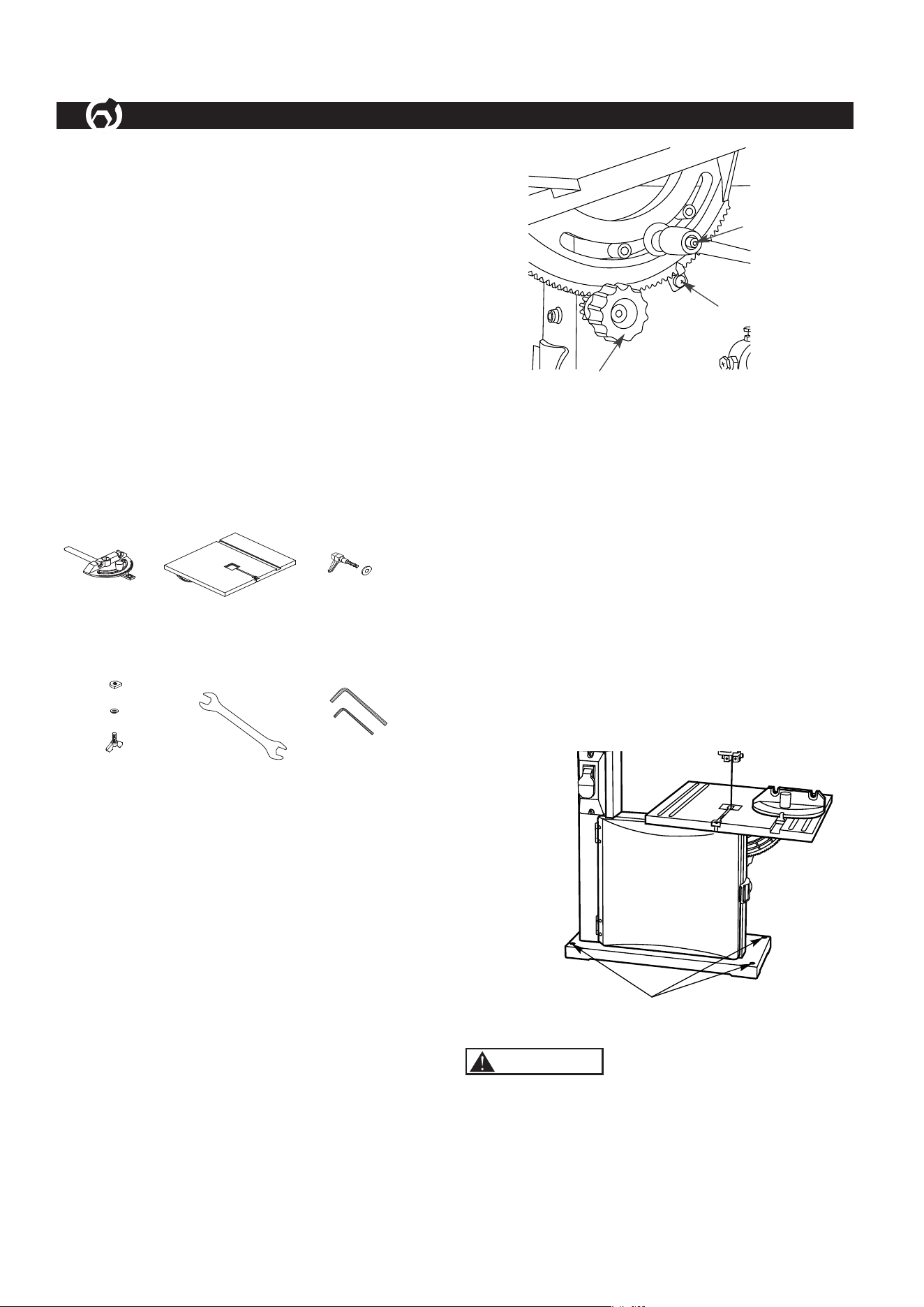
INSTALL TABLE ASSEMBLY
Refer to Figure 1 and 2
• Locate and remove the trunnion knob.
• Remove ths table locking insert assembly from the table.
• Place the table assembly onto the saw frame.
• Replace and secure the trunnion knob.
• Use the provided lock screw handle with washer to
secure the table assembly to the saw frame.
• Reinstall the Table Locking Insert Assembly.
• After blade tracking and tension have been verified and
the blade guides properly set, calibrate the table tilt
position. Using a combination square, set the table
perpendicular to the saw blade and zero the pointer of
the tilt scale.
Figure 2
MOUNT BAND SAW
Refer to Figure 3
• The band saw must be installed in a well-lit area with
correct power supply.
• Four mounting holes are on the base of band saw. If
pre-drilled holes do not exist on the bench surface, drill
four holes.
• Band saw can be installed on either a workbench or a
tool stand by using bolts. Lock washers, and hex nuts.
(mounting hardware not included)
• The band saw must be bolted to a firm and level
surface.
• There must be enough clearance for the moving work
piece during operation. There must be enough room for
safe operation of the machine.
Figure 3
POWER SOURCE
Do not connect to the power source until the machine is
completely assembled.
The machine is wired for 120 volts, 60 HZ alternating
current. Before connecting the machine to the power
source, make sure the switch is in the “OFF” position.
ASSEMBLY
2
B C
E FD
A
Trunnion Knob
Lock Screw Handle
Pointer
Mounting Holes
WARNING
Loading ...
Loading ...
Loading ...