Operating and installation
instructions
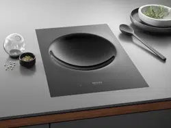
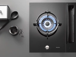
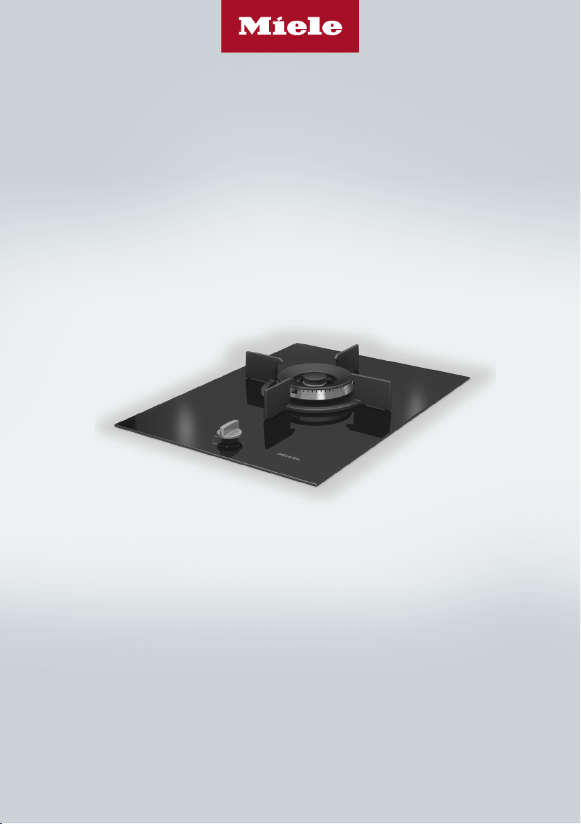
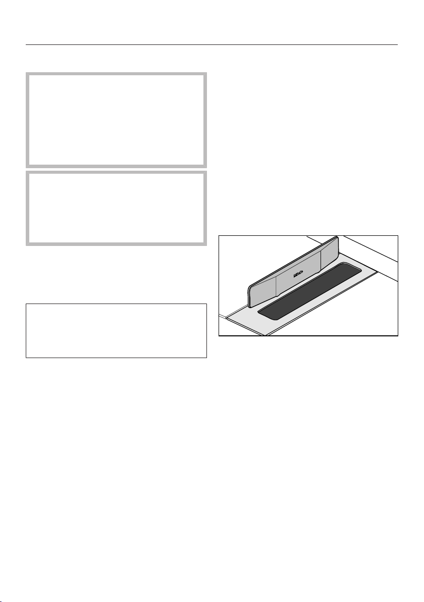
SmartLine gas wok
To avoid the risk of accidents or damage to the appliance it is essen-
tial to read these instructions before it is installed and used for the
first time.
en-GB M.-Nr. 11 503 470

2
This appliance can be used in countries other than those specified on the appli-
ance and in these operating and installation instructions. It is, however, set up
for connection to the gas and electricity supplies in the countries specified. For
trouble-free operation of the appliance, it is best to use it in the countries spe-
cified for use.
For use in other countries, please contact Miele in your country.

Gas-heated appliances
3
Safety precautions to take if you smell gas
Turn off the gas emergency control valve immediately.
This is usually located near the gas meter.
Eliminate all sources of ignition in a safe manner.
Do not smoke, light cigarette lighters or matches.
Do not operate electrical lights or switches, i.e. do not switch them “On” or
“Off”.
Open all doors and windows to ventilate the area.
If the smell of gas persists, evacuate the building.
In the UK you must now:
Call the Gas Emergency Contact Centre (Tel: 0 800 111 999).
For any gas work in the UK always use a Gas Safe registered engineer.
In other countries please follow relevant country specific procedures on gas.

Contents
4
Warning and Safety instructions...................................................................... 6
Caring for the environment .............................................................................. 17
Guide to the appliance...................................................................................... 18
Wok ..................................................................................................................... 18
Control knobs...................................................................................................... 19
Burner.................................................................................................................. 20
Accessories supplied .......................................................................................... 21
Before using for the first time .......................................................................... 22
Cleaning the SmartLine element for the first time............................................... 22
Switching on the SmartLine element for the first time ........................................ 22
Pans .................................................................................................................... 23
Operation............................................................................................................ 25
Switching on........................................................................................................ 25
FlameGuard......................................................................................................... 25
Adjusting the flame.............................................................................................. 26
Switching off........................................................................................................ 26
Tips on saving energy ...................................................................................... 27
Safety features................................................................................................... 28
Thermo-electric flame failure monitor ................................................................. 28
Cleaning and care ............................................................................................. 29
Cleaning the ceramic surface.............................................................................. 30
Cleaning the rotary controls ................................................................................ 31
Cleaning the trivets.............................................................................................. 31
Cleaning the burners ........................................................................................... 32
Assembling the burners ................................................................................. 32
Problem solving guide ...................................................................................... 33
Optional accessories ........................................................................................ 35
After sales service............................................................................................. 36
Contact in the event of a fault ............................................................................. 36
Data plate ............................................................................................................ 36
Warranty .............................................................................................................. 36
Installation.......................................................................................................... 37
Safety instructions for installation ....................................................................... 37
Safety distances.................................................................................................. 39

Contents
5
Installation notes – surface-mounted.................................................................. 42
Worktop cutout – surface-mounted .................................................................... 44
Spacer bars – surface-mounted.......................................................................... 47
Installation dimensions–Surface-mounted........................................................ 48
Installation – surface-mounted............................................................................ 49
Installation notes – flush-fit ................................................................................. 51
Worktop cutout – flush-fit.................................................................................... 53
Spacer bars – flush-fit ......................................................................................... 56
Installation dimensions–Flush-fit....................................................................... 57
Installation – flush-fit ........................................................................................... 58
Gas connection ................................................................................................... 60
Burner ratings...................................................................................................... 63
Electrical connection ........................................................................................... 64
Converting to another gas type ....................................................................... 65
Jet table............................................................................................................... 65
Changing the jets ................................................................................................ 65
Changing the main jets................................................................................... 66
Changing the small jets.................................................................................. 66
Functional check ................................................................................................. 67
Product data sheets ......................................................................................... 68
Warning and Safety instructions
6
This wok complies with all current local and national safety re-
quirements. Inappropriate use can, however, lead to personal in-
jury and material damage.
Read the operating and installation instructions carefully before
using the wok. They contain important information on safety, in-
stallation, use and maintenance. This prevents both personal injury
and damage to the wok.
In accordance with standard IEC60335-1, Miele expressly and
strongly advises that you read and follow the instructions in the
chapter on installing the wok as well as the safety instructions and
warnings.
Miele cannot be held liable for injury or damage caused by non-
compliance with these instructions.
Keep these instructions in a safe place and pass them on to any
future owner.

Warning and Safety instructions
7
Correct application
This wok is designed for domestic use and for use in similar envir-
onments.
This wok is not intended for outdoor use.
This wok is intended for domestic use only to cook food and keep
it warm. Any other use is not supported by the manufacturer and
could be dangerous.
This wok can only be used by people with reduced physical, sens-
ory or mental capabilities or lack of experience and knowledge if
they are supervised whilst using it. They may only use it unsuper-
vised if they have been shown how to use it in a safe way and under-
stand the hazards involved.

Warning and Safety instructions
8
Safety with children
Children under 8 years of age must be kept away from the wok
unless they are constantly supervised.
Children aged 8 and older may only use the wok without supervi-
sion if they have been shown how to use it in a safe manner. Chil-
dren must be able to understand and recognise the possible dangers
caused by incorrect operation.
Children must not be allowed to clean the wok unsupervised.
Please supervise children in the vicinity of the wok and do not let
them play with it.
The wok gets hot when in use and remains hot for a while after
being switched off. Keep children well away from the appliance until
it has cooled down and there is no danger of burning.
Danger of burning!
Do not store anything which might arouse a child's interest in stor-
age areas above or behind the wok. Otherwise they could be temp-
ted into climbing onto the wok with the risk of burning themselves.
Risk of burning and scalding. Place pots and pans on the cooking
zone in such a way that children cannot pull them down and burn
themselves.
Danger of suffocation! Whilst playing, children may become en-
tangled in packaging material (such as plastic wrapping) or pull it
over their head with the risk of suffocation. Keep packaging material
away from children.

Warning and Safety instructions
9
Technical safety
Unauthorised installation, maintenance and repairs can cause
considerable danger for the user. Installation, maintenance and re-
pairs must only be carried out by a Miele authorised technician.
Damage to the wok can compromise your safety. Check the wok
for visible signs of damage. Do not use a damaged wok.
Temporary or permanent operation on an autonomous power sup-
ply system or a power supply system that is not synchronised with
the mains power supply (e.g. island networks, back-up systems) is
possible. A prerequisite for operation is that the power supply sys-
tem complies with the specifications of EN50160 or an equivalent
standard.
The function and operation of the protective measures provided in
the domestic electrical installation and in this Miele product must
also be maintained in isolated operation or in operation that is not
synchronised with the mains power supply, or these measures must
be replaced by equivalent measures in the installation. As described,
for example, in the current version of BS OHSAS 18001–2 ISO
45001.
The electrical safety of this wok can only be guaranteed when cor-
rectly earthed. It is essential that this standard safety requirement is
met. If in any doubt please have the electrical installation tested by a
qualified electrician.
Before connecting the wok to the mains supply, ensure that the
connection data on the data plate (voltage and frequency) match the
mains electricity supply.
This data must be checked before connecting the appliance. Consult
a qualified electrician if in any doubt.
Do not connect the wok to the mains electricity supply by a multi-
socket unit or an extension lead. These do not guarantee the re-
quired safety of the appliance (fire hazard).

Warning and Safety instructions
10
For safety reasons, this wok may only be used after it has been
built in.
This wok must not be used in a non-stationary location (e.g. on a
ship).
Never open the casing of the wok.
Touching or tampering with electrical connections or components
and mechanical parts is highly dangerous to the user and can cause
operational faults.
While the wok is under warranty repairs should only be under-
taken by a Miele authorised service technician. Otherwise the war-
ranty is invalidated.
Miele can only guarantee the safety of the appliance when genu-
ine original Miele replacement parts are used. Faulty components
must only be replaced by Miele spare parts.
The wok is not intended for use with an external timer switch or a
remote control system.
Connection to the gas supply must be carried out by a suitably
qualified gas fitter (e.g. a Gas Safe registered technician in the U.K).
The wok may be connected to the electrical supply by a fused plug
and switched socket. If you wish to connect it to a fused spur con-
nection, or if the plug has been removed or the connection cable is
not supplied with a plug, the wok must be connected to the mains
supply by a suitably qualified electrician.
If the mains connection cable is damaged, it must be replaced
with a special mains connection cable by a qualified electrician (see
“Electrical connection” in the “Installation” chapter).

Warning and Safety instructions
11
During installation, maintenance and repair work, the wok must be
completely disconnected from the mains electricity supply. The gas
inlet valve must be closed. It is only completely isolated from the
electricity supply when:
- the mains fuse has been disconnected or
- the screw-out fuse is removed (in countries where this is applic-
able),
- the plug (if present) is removed from the socket. To do this, pull
the plug not the mains connection cable.
- The gas inlet valve is closed.
Risk of electric shock.
Do not use the wok if it is faulty, or if the ceramic surface is cracked,
chipped or damaged in any way. Switch it off immediately. Discon-
nect it from the mains electricity and gas supply. Call the Customer
Service Department.
If the wok is built in behind a furniture front (e.g. a door), do not
close the door while the wok is in use. Heat and moisture can build
up behind the closed door. This can result in damage to the wok, the
housing unit and the floor. Leave the furniture door open until the
wok has cooled down completely.
In areas which may be subject to infestation by cockroaches or
other vermin, pay particular attention to keeping the appliance and
its surroundings clean at all times. Any damage caused by cock-
roaches or other vermin will not be covered by the warranty.
Carry out an annual visual inspection of the gas lines and gas ap-
pliances in your home. This inspection must comply with applicable
national regulations.

Warning and Safety instructions
12
Correct use
The wok gets hot when in use and remains hot for some time after
being switched off. Do not touch the appliance if there is a possibility
that it could still be hot.
Do not use the wok to heat up the room.
Due to the high temperatures radiated, objects left near the wok
could catch fire.
Overheated fat and oil can ignite and catch fire. Never leave the
wok unattended. Do not attempt to extinguish burning oil or fat with
water.
Switch the wok off and carefully smother the flames with a fire
blanket or a damp tea towel.
Do not leave the SmartLine element unattended whilst it is being
used. It should be continually monitored whilst boiling and flash fry-
ing.
Flames could set the grease filters of a cooker hood on fire. Do
not flambé under a cooker hood.
Spray canisters, aerosols and other inflammable substances can
ignite when heated. Therefore do not store such items or substances
in a drawer under the wok. Cutlery inserts must be heat-resistant.
Do not heat an empty pan.
Do not heat up food in closed containers e.g. tins or sealed jars
on the wok, as pressure will build up in the container which could
cause it to explode.
Do not cover the wok, e.g. with a cover, a cloth or protective foil.
The material could catch fire, shatter or melt if the appliance is
switched on by mistake or if residual heat is still present.

Warning and Safety instructions
13
If the appliance is switched on by mistake, or if there is residual
heat present, there is the risk of any metal items placed on the wok
(e.g. cutlery) heating up. Other materials can melt or catch fire. Do
not use the appliance as a resting place for anything.
You could burn yourself on the hot wok. Protect your hands with
heat-resistant pot holders or gloves when handling hot pots and
pans. Do not let them get wet or damp, as this causes heat to trans-
fer through the material more quickly with the risk of scalding or
burning yourself on steam. Be sure to keep all textiles away from the
gas flames. Do not use oversized cloths, tea towels or other similar
materials.
When using an electrical appliance, e.g. a hand-held food blender,
near the wok, ensure that the cable of the electrical appliance cannot
come into contact with the hot wok. The insulation on the cable
could become damaged.
Even a light object can cause damage in certain circumstances.
Do not drop anything on the ceramic surface.
Plastic and aluminium foil containers melt at high temperatures.
Do not use plastic or aluminium foil containers.
When a control knob is pressed down, a spark is generated on the
ignitor. Do not press down the control knob while you are cleaning or
touching the wok or a burner in the vicinity of an ignitor.
If a cooker hood is installed above the wok, ensure that the burn-
ers are always covered with a pan when in use. Otherwise flames
could reach the cooker hood, parts of which could then be damaged
or even set on fire.
Only light the gas burners after all burner parts have been properly
assembled.

Warning and Safety instructions
14
Do not use pans with a diameter that is larger or smaller than the
stated dimensions (see “Pans”). A pan which is too small will be un-
stable on the pan support. If the diameter is too large, heat emitted
from the bottom of the pan may damage the worktop, walls with
poor heat resistance (e.g. panelled walls), or parts of the wok. Miele
will not accept responsibility for this type of damage.
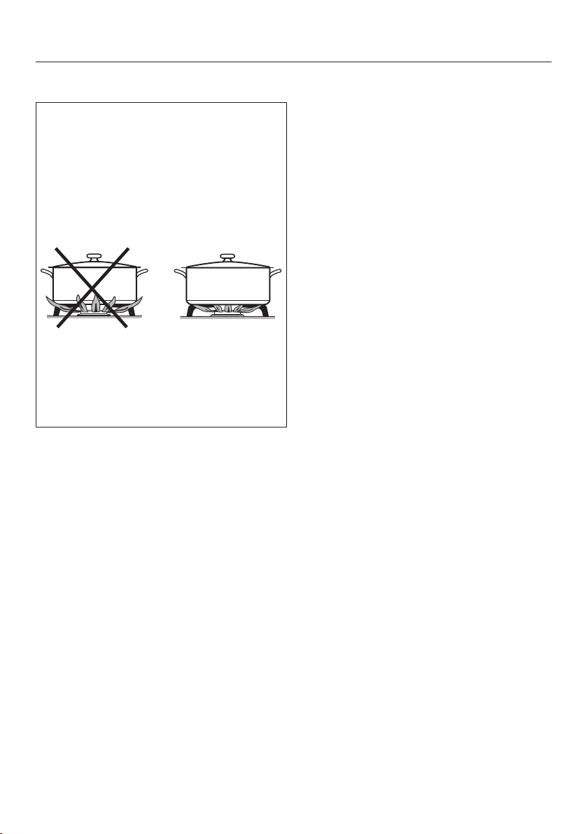
Ensure that the flames from the burner do not spread out beyond
the base and up the sides of the pan.
Do not use pans with very thin bases. This could damage the
wok.
The pan support supplied with the appliance must always be
used. Never place a pan on the burner itself.
Replace the pan supports carefully to avoid scratching the sur-
face.
Do not use or store flammable materials near this appliance.
Remove all grease spatters and other combustible (food) residues
from the wok burner as soon possible. They are a fire hazard.
The use of the wok creates heat, moisture and combustion
products in the room where it is installed. Make sure that the appli-
ance is installed in a location with sufficient ventilation. Natural vent-
ilation openings should not be blocked. Alternatively, a mechanical
ventilation device (e.g. a cooker hood) can be installed.
Prolonged intensive use of the wok may require additional ventila-
tion of the room, e.g., by opening a window, or by operating the
cooker hood on a higher setting.
If the wok has not been used for a longer period of time, it should
be thoroughly cleaned before it is used again. It is also advisable to
have it tested for safety. This should be done at regular intervals.

Warning and Safety instructions
15
If you are operating a gas cooking element directly next to the
downdraft extractor, the FlameGuard must be placed between the
downdraft extractor and the element.

Warning and Safety instructions
16
Cleaning and care
Do not use a steam cleaning appliance to clean this wok.
The steam could reach electrical components and cause a short cir-
cuit.
Miele will guarantee to supply functional spare parts for a min-
imum of 10years and up to 15years following the discontinuation of
your CombiSet.
Caring for the environment
17
Disposal of the packing mater-
ial
The packaging is designed to protect
the appliance from damage during
transportation. The packaging materials
used are selected from materials which
are environmentally friendly for disposal
and should be recycled.
Recycling the packaging reduces the
use of raw materials in the manufactur-
ing process and also reduces the
amount of waste in landfill sites.
Disposing of your old appli-
ance
Electrical and electronic appliances of-
ten contain valuable materials. They
also contain specific materials, com-
pounds and components, which were
essential for their correct function and
safety. These could be hazardous to hu-
man health and to the environment if
disposed of with your domestic waste
or if handled incorrectly. Please do not,
therefore, dispose of your old appliance
with your household waste.
Please dispose of it at your local com-
munity waste collection / recycling
centre for electrical and electronic ap-
pliances, or contact your dealer or
Miele for advice. You are also respons-
ible for deleting any personal data that
may be stored on the appliance being
disposed of. Please ensure that your
old appliance poses no risk to children
while being stored prior to disposal.
Guide to the appliance
18
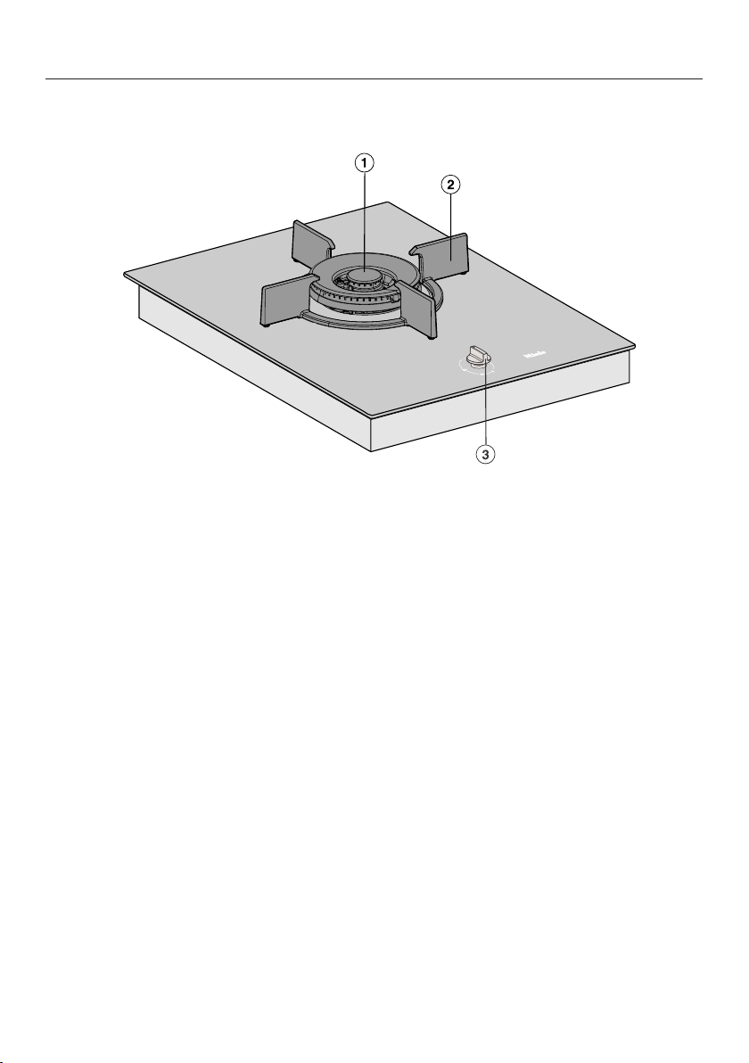
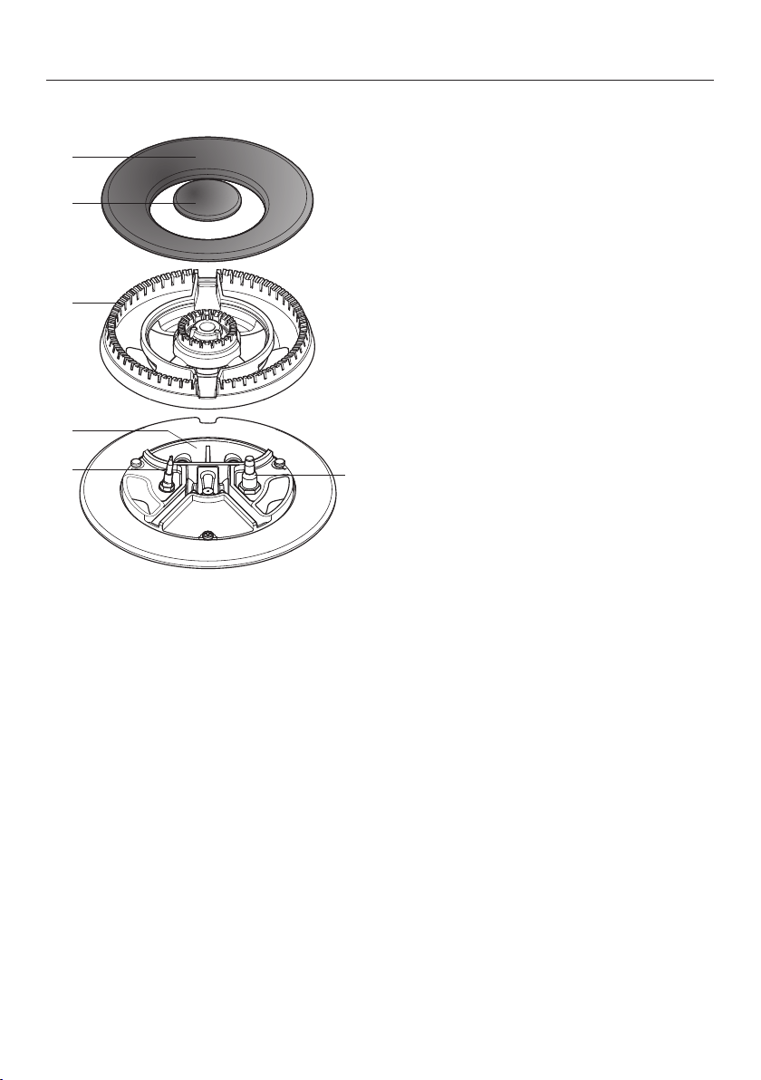
Wok
a
Wok burner
b
Trivet
c
Rotary controls
Guide to the appliance
19
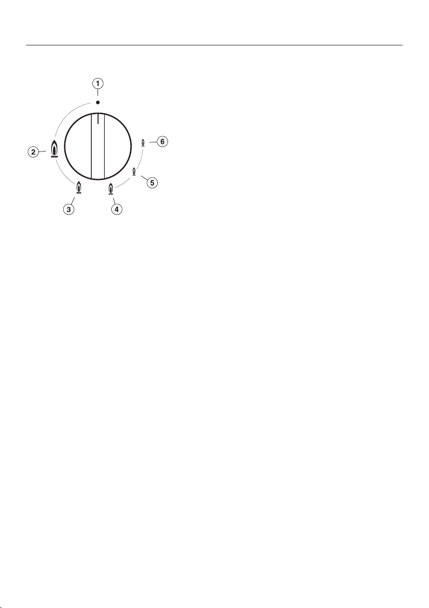
Control knobs
a
Burner off
The gas supply is turned off
b
Strongest flame
The outer and inner burners are on the highest setting
c
Strong flame
The outer burner is on the lowest setting, the inner burner on the highest setting
d
Over-ignition position
The outer burner is ignited by changing from the lowest to the highest setting
e
Weak flame
The outer burner is off, the inner burner is on the highest setting
f
Weakest flame
The outer burner is off, the inner burner is on the lowest setting
Guide to the appliance
20
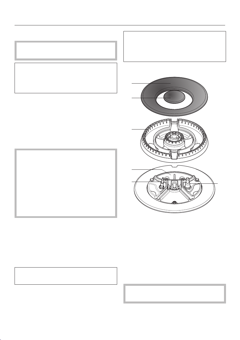
Burner
a
b
c
e
f
d
a
Outer burner cap
b
Inner burner cap
c
Burner head
d
Burner base
e
Thermocouple
f
Ignition electrode
Guide to the appliance
21
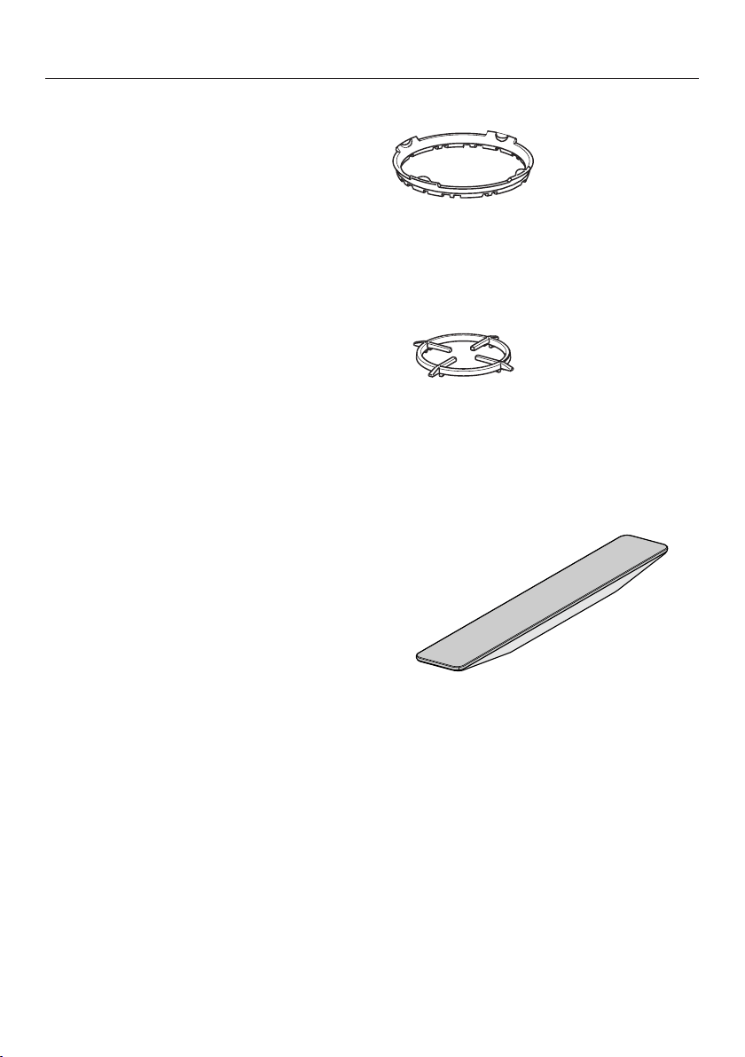
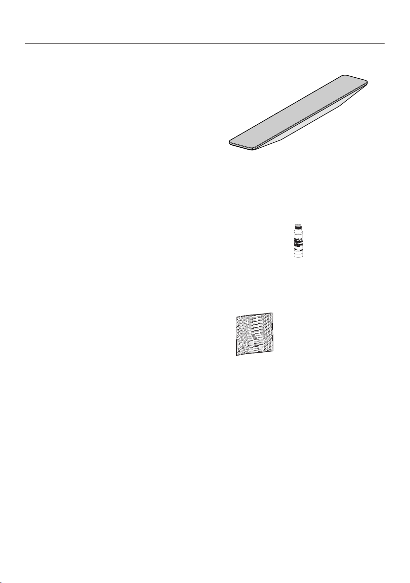
Accessories supplied
The accessories supplied with your ap-
pliance as well as a range of optional
ones are available to order from Miele
(see “Optional accessories”).
Wok ring
The wok ring supplied gives additional
stability to the wok, especially to woks
with a rounded base.
Combination trivet
The combination trivet supplied must
be used if you are using pans with a
smaller base diameter than that spe-
cified in the chart for suitable pans.
FlameGuard
For installing between the downdraft
extractor and a gas cooking element

Before using for the first time
22
Please stick the extra data plate for
the appliance supplied with this doc-
umentation in the space provided in
the “After sales service” section of
this booklet.
Remove any protective wrapping and
stickers.
Cleaning the SmartLine ele-
ment for the first time
Clean all removable parts of the burn-
ers with a solution of warm water and
a small amount of washing-up liquid
applied with a soft sponge. Dry all
parts thoroughly after cleaning and
then reassemble the burners (see
“Cleaning and care”).
Clean the ceramic surface with a
damp cloth, and then wipe dry.
Switching on the SmartLine
element for the first time
The metal components have a protect-
ive coating. Smells and possibly some
vapours may occur when the SmartLine
element is used for the first time.
The smell and any vapours given off do
not indicate a faulty connection or ap-
pliance and they are not hazardous to
health.
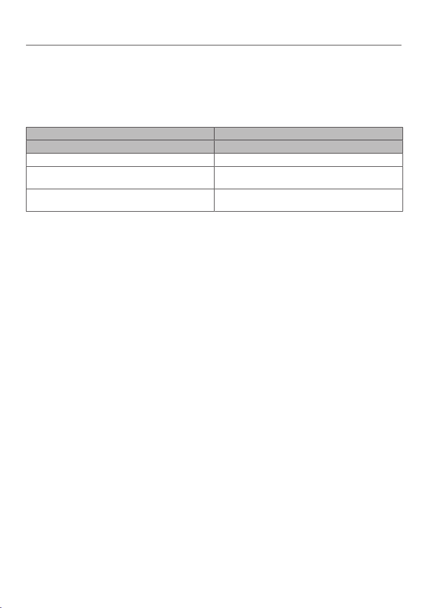
Pans
23
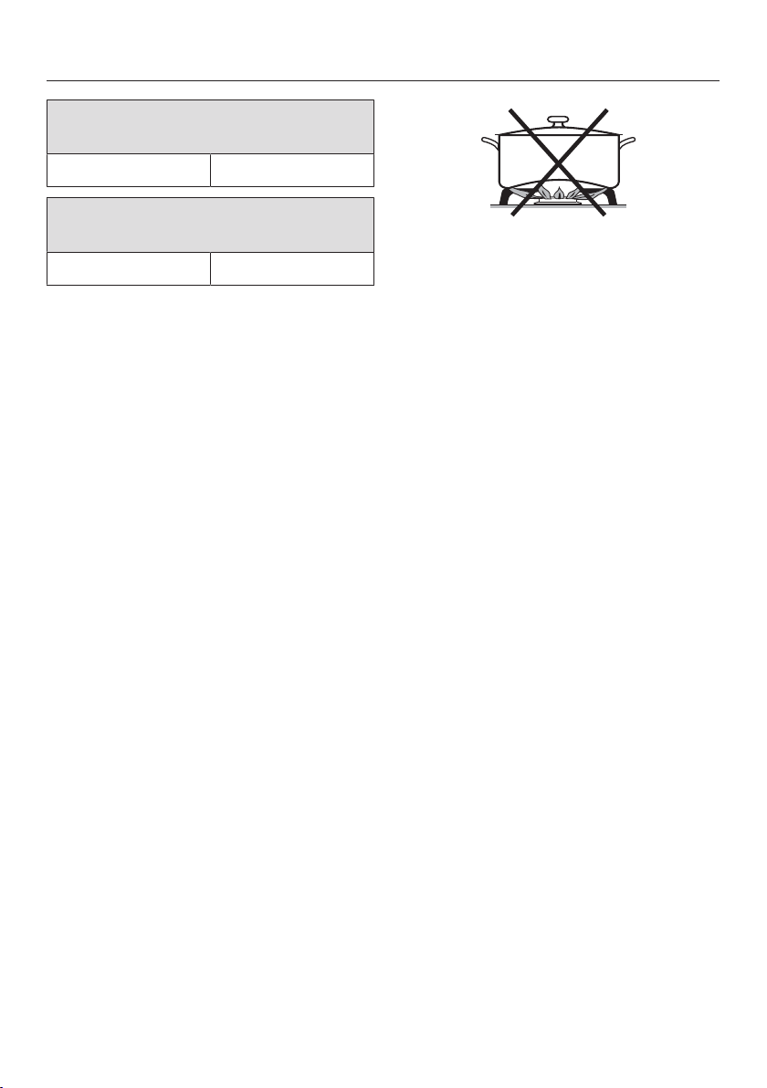
Minimum cookware base diameter
[cm]
Pots/pans 14
Maximum diameter at top of cook-
ware [cm]
Pots/pans 30
- Observe the dimensions given in the
chart. Using pans that are too large
can cause the flames to spread out
and damage the surrounding worktop
or other appliances. Using pans of
the correct size improves efficiency.
Pans that are smaller than the trivets
and pans that do not stand safely
(without wobbling) on the trivets are
dangerous and should not be used.
- Remember when purchasing new
pans that manufacturers usually refer
to the diameter at the top of the pan
in their documentation, and not to the
base diameter.
- All heat-resistant cookware is suitable
for use.
- Cookware with a thick base is prefer-
able as the heat is distributed evenly.
With thin bases, there is the risk that
food will overheat in places. There-
fore it should be stirred more fre-
quently.
- Always place the cookware on the
trivet supplied. Do not place cook-
ware directly on the burners.
- Place the cookware on the trivet in
such a way that it cannot tip over. A
little movement is quite normal and
not a cause for concern.
- Do not use pots or pans with an
edge-supported base.
Pans
24
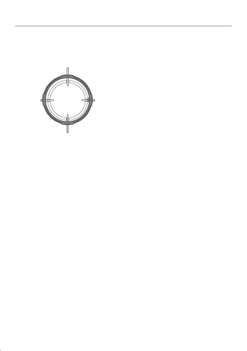
Wok ring
Use the wok ring supplied to give ad-
ditional stability to pans, especially to
woks with a rounded base.
Place the wok ring on the pan sup-
port so that it sits securely in position
and cannot move (see diagram).
The wok is unique among cookware in
that it has a small base diameter and a
large rim diameter (usually 35-40cm).
Wok pans are ideal for use on the wok
burner.
Combination trivet
Use the small trivet supplied for small
pans. The pan will then be stable on the
burner and not tip over.
Operation
25
Switching on
If you are operating a gas cooking
element next to a downdraft ex-
tractor, this will affect the gas cook-
ing element's function.
Place the FlameGuard between the
gas cooking element and the
downdraft extractor.
Risk of fire with overheated food.
Unattended food can overheat and
catch alight.
Do not leave the wok unattended
whilst it is being used.
Press in the relevant rotary control
and turn it anticlockwise to the large
flame symbol. The ignition electrode
will “click” and ignite the gas.
When the rotary control is operated, a
spark is automatically produced on all
burners. This is normal and does not
indicate a fault.
When a flame is visible, keep the
rotary control pressed down for 5–
10seconds, and then let it go.
If the burner does not ignite, turn the
rotary control to the position. Ventil-
ate the room or wait for at least
1minute before trying again. When
making another ignition attempt, it
may be necessary to hold the rotary
control for longer.
If the burner does not ignite the
second time, turn the rotary control
back to the position and see “Prob-
lem solving guide”.
Switching on during a power outage
If there is an interruption to the electri-
city supply, the gas can be ignited
manually, e.g. with a match.
Press in the relevant control and turn
it anti-clockwise to the large flame
symbol.
Hold the control pressed in and light
the gas at the burner with a match.
Keep the control pressed in for a fur-
ther 5-10seconds and then release it.
FlameGuard
Install the FlameGuard directly next to
the downdraft extractor when you are
operating a gas cooking element.
Operation
26
Adjusting the flame
As the outer part of the flame is much
hotter than the centre, the tips of the
flames should stay beneath the pan
base. Flame tips which extend beyond
the sides of the pan merely warm up
the air in the room and can also dam-
age pan handles and increase the risk
of injury.
There is a resistance at the 6 o'clock
position to prevent you turning the
control to the high or low setting unin-
tentionally. Press the control knob
down to move past this resistance.
Adjust the flame so that it does not
spread out beyond the sides of the
pan.
To move from the high to the low set-
ting, turn the control anti-clockwise
until it meets a resistance. Then press
it down and continue to turn it past
the resistance before releasing it. You
can now select the setting you re-
quire.
To move from the low to the high set-
ting, turn the control clockwise until it
meets a resistance. Then press it
down and continue to turn it past the
resistance before releasing it. You can
now select the setting you require.
Switching off
Turn the rotary control clockwise to
the position.
The gas supply is cut off and the flame
goes out.

Tips on saving energy
27
- Use a pan lid whenever possible to
minimize heat loss.
- Wide, shallow pans are preferable to
tall, narrow ones. They will heat up
faster.
- Cook with as little water as possible.
- Reduce the size of the flame once the
water has come to the boil or the oil
is hot enough to fry in.
- Use a pressure cooker to reduce
cooking times.
Safety features
28
Thermo-electric flame failure
monitor
Your wok is equipped with a thermo-
electric flame failure monitor. If a gas
flame is extinguished, e.g. by food boil-
ing over or by a draught, the gas supply
is switched off. This prevents the re-
lease of gas. If you turn the rotary con-
trol to the position, the burner is ready
for use again.
The thermo-electric flame failure mon-
itor operates independently from the
electricity supply. This means that it
will still work if the wok is used during
a power cut.
Cleaning and care
29
Danger of burning due to hot
surfaces.
The surfaces will be hot after cook-
ing.
Switch the wok off.
Allow the surfaces to cool down be-
fore cleaning the wok.
Risk of damage due to moisture
ingress.
The steam from a steam cleaning ap-
pliance could reach live electrical
components and cause a short cir-
cuit.
Do not use a steam cleaner to clean
the wok.
All surfaces could be discoloured or
damaged if unsuitable cleaning
agents are used. All surfaces are
susceptible to scratching.
Remove all cleaning agent residues
immediately.
Never use abrasive sponges or
cleaning agents.
Food boiling over can cause discol-
oration of the burner components.
Remove any soiling and salt and
sugar splashes immediately.
When a control knob is pressed
down, a spark is generated on the ig-
nitor. Do not press down the control
knob while you are cleaning or
touching the wok or a burner in the
vicinity of an ignitor.
Allow the SmartLine element to cool
down before cleaning.
Clean the SmartLine element and ac-
cessories after each use.
Dry the SmartLine element thoroughly
after every cleaning to avoid limes-
cale residue.
Unsuitable cleaning agents
To avoid damaging the surfaces of the
appliance, do not use:
- cleaning agents containing soda, al-
kalines, ammonia, acids or chlorides
- cleaning agents containing descaling
agents
- stain and rust removers
- abrasive cleaning agents, e.g.
powder cleaners and cream cleaners
- solvent-based cleaning agents
- dishwasher cleaner
- oven sprays
- glass cleaning agents
- hard, abrasive brushes or sponges
(e.g. pot scourers), or sponges which
have been previously used and still
contain abrasive cleaning agents
- melamine eraser blocks
Cleaning and care
30
Cleaning the ceramic surface
Risk of damage by pointed ob-
jects.
The seal between the SmartLine ele-
ment and the worktop could suffer
damage.
Do not use pointed objects for clean-
ing.
Not all soiling and residues can be
removed using a solution of wash-
ing-up liquid.
An invisible film can develop that can
lead to discolouration of the glass
ceramic surface. This discolouration
cannot be removed.
Clean the ceramic surface regularly
with a proprietary ceramic glass
cleaning agent.
Remove any coarse soiling with a
damp cloth and more stubborn soil-
ing with a shielded scraper blade
suitable for use on glass.
Then clean the ceramic glass surface
with the Miele ceramic and stainless
steel hob cleaner (see “optional ac-
cessories”) or with a proprietary
ceramic glass cleaner applied with
kitchen paper or a clean cloth. Do not
apply the cleaner while the hob is still
hot, as this can result in marking.
Please follow the cleaning agent
manufacturer's instructions.
Finally wipe the glass ceramic surface
with a damp cloth and polish with a
soft, dry cloth.
Residues can burn onto the hob the
next time it is used and cause damage
to the glass ceramic surface. Ensure
that all cleaning agent residues are re-
moved.
Spots caused by limescale, water
and aluminium residues (spots with a
metallic appearance) can be removed
using Miele's ceramic and stainless
steel hob cleaner.
Danger of burning due to hot
surfaces.
The surfaces get hot during cooking.
Wear oven gloves when removing
residues of sugar, plastic or alu-
minium foil from a hot ceramic sur-
face with a shielded scraper blade.
Should any sugar, plastic or alu-
minium foil spill or fall onto the hot
ceramic surface while it is in use,
switch off the cooking zone.
Then carefully scrape off these
residues immediately whilst they are
still hot, using a scraper blade suit-
able for use on glass.
Afterwards, clean the ceramic surface
in its cooled state, as described
above.

Cleaning and care
31
Cleaning the rotary controls
Clean the rotary control(s) using a
solution of warm water and a little
washing-up liquid applied with a soft
sponge. Soften any stubborn soiling
beforehand.
Dry the control(s) with a clean cloth.
Cleaning the trivets
Remove the trivets.
Clean the trivets in a dishwasher or
with a solution of warm water and a
little washing-up liquid applied with a
soft sponge. Soften any stubborn
soiling beforehand.
Dry the trivets thoroughly with a clean
cloth.
Cleaning and care
32
Cleaning the burners
Do not clean any parts of the burners
in a dishwasher.
The surface of the burner cap will be-
come duller with time. This is com-
pletely normal and does not indicate
material deterioration.
The burner should be dismantled and
then cleaned by hand using a solu-
tion of warm water and a little wash-
ing-up liquid applied with a soft
sponge.
Clean any soiling from the flame
openings.
Danger of explosion.
Blocked flame openings can cause a
dangerous build-up of gas in the
base of the hob which could ignite
and cause an explosion. This can
lead to damage to the appliance and
injury.
Ensure the flame openings are kept
clean at all times.
Parts of the burner that cannot be re-
moved should be wiped clean with a
damp cloth only.
The ignitor and thermocouple should
be very carefully wiped clean using a
well wrung-out cloth.
The ignitor must not get wet, other-
wise it will not spark.
Finally dry everything thoroughly with
a clean cloth. Make sure that the
flame openings are completely dry.
The surface of the burner cap will be-
come duller with time. This is com-
pletely normal and does not indicate
material deterioration.
Assembling the burners
a
b
c
e
f
d
Place the burner head onto the
burner base so that the thermo-
couple and the ignition elec-
trode extend through their respect-
ive holes in the burner head. The
burner head must click into place
correctly.
Then place the burner caps and
in position.
Ensure that all parts of the burner are
reassembled in the correct order.
Problem solving guide
33
Many malfunctions and faults that can occur in daily operation can be easily
remedied. Time and money will be saved because a service call will not be
needed.
The following guide may help you to find the reason for a malfunction or a fault,
and to correct it.
Problem Cause and remedy
The burners do not ig-
nite when the hob is be-
ing used for the first
time or after it has been
out of use for a longer
period.
There could be an air lock in the gas pipe.
You may need to make several attempts before the
burner ignites successfully.
The burner does not
light after several at-
tempts.
There is a technical fault.
Turn all of the controls clockwise to the position
and interrupt the power supply to the hob for a few
seconds.
The burner is not correctly assembled.
Assemble the burner correctly.
The gas shut-off device has not been opened.
Open the gas shut-off device.
The burner is wet and/or dirty.
Clean and dry the burner.
The flame openings are blocked and/or wet.
Clean and dry the flame openings.
The gas flame goes out
after ignition.
The flames do not touch the thermocouple and the
burner does not get hot enough:
The burner parts are not positioned correctly.
Assemble the burner components correctly.
The thermocouple is dirty.
Remove any soiling.
The flame suddenly
looks different.
The burner parts are not positioned correctly.
Position the burner parts correctly.
The burner head or the holes in the burner cap are
dirty.
Remove any soiling.
Problem solving guide
34
Problem Cause and remedy
The gas flame goes out
during use.
The burner parts are not positioned correctly.
Position the burner parts correctly.
The electronic ignition
device on the burner is
not working.
The mains fuse has tripped.
If necessary, contact a qualified electrician or
Miele Service for assistance.
There is food residue stuck between the ignitor and
the burner cap.
The thermocouple is dirty.
Remove any soiling (See “Cleaning and care”).
Optional accessories
35
Miele offer a comprehensive range of
useful accessories as well as cleaning
and conditioning products for your
Miele appliances.
These products can be ordered through
the Miele Webshop.
They can also be ordered from Miele
(see end of this booklet for contact de-
tails) or from your Miele dealer.
FlameGuard
For installing between the downdraft
extractor and a gas cooking element
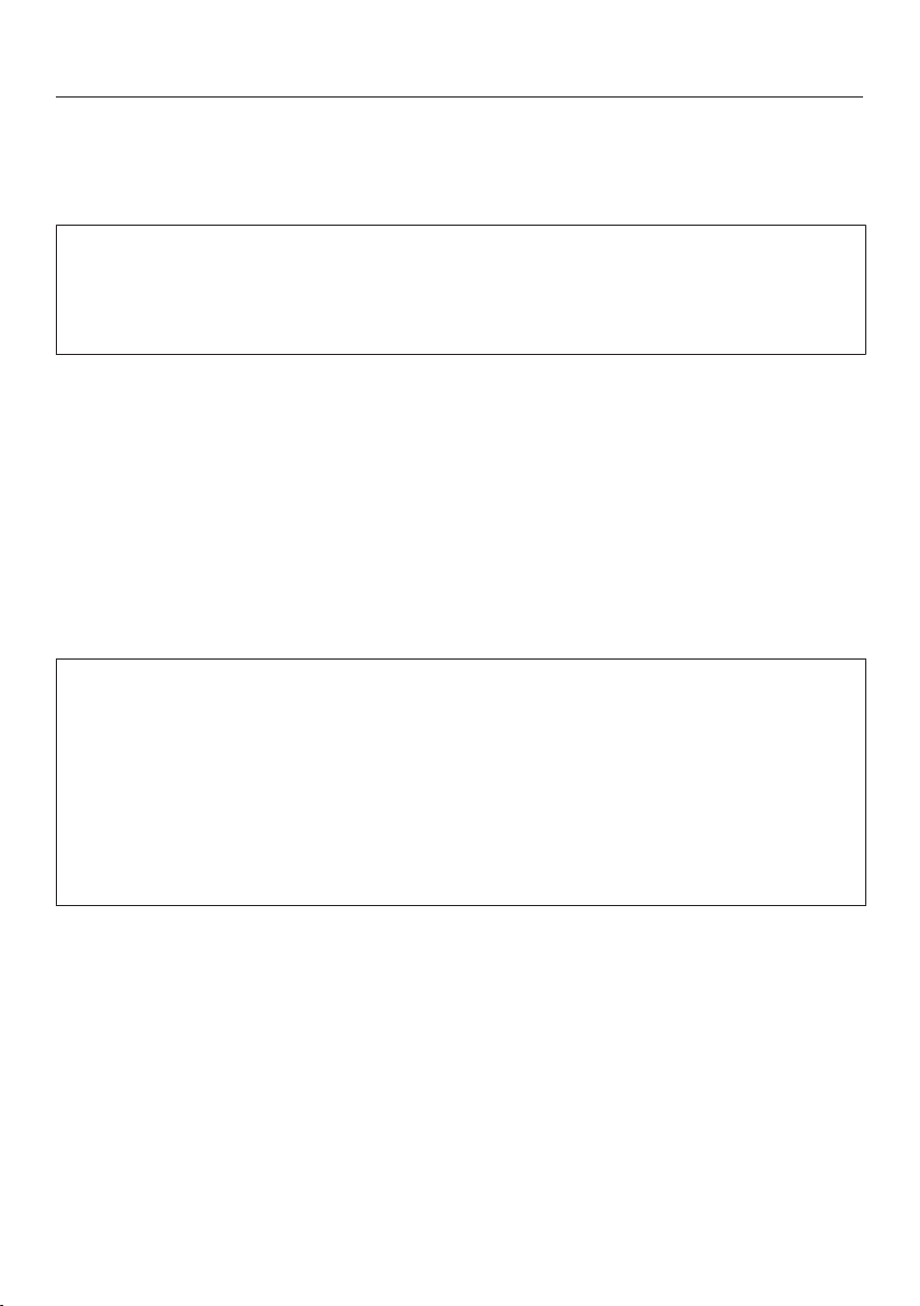
Ceramic and stainless steel
hob cleaner 250ml
Removes heavy soiling, limescale de-
posits and aluminium residues
Microfibre cloth
Removes finger marks and light soiling
After sales service
36
Contact in the event of a fault
In the event of any faults which you cannot remedy yourself, please contact your
Miele dealer or the Miele Customer Service Department.
You can book a Miele Customer Service Department call-out online at
www.miele.com/service.
Contact information for the Miele Customer Service Department can be found at
the end of this document.
Please quote the model identifier and serial number of your appliance (Fabr./SN/
Nr.) when contacting the Miele Customer Service Department. This information
can be found on the data plate.
Please note that telephone calls may be monitored and recorded for training pur-
poses and that a call-out charge will be applied to service visits where the problem
could have been resolved as described in this booklet.
Data plate
Stick the extra data plate supplied with the appliance here. Make sure that the
model number matches the one specified on the back cover of this document.
Warranty
For information on the appliance warranty specific to your country please contact
Miele. See back cover for address.
In the UK, your appliance warranty is valid for 2 years from the date of purchase.
However, you must activate your cover by calling 0330 160 6640 or registering on-
line at www.miele.co.uk.
Installation
*INSTALLATION*
37
Safety instructions for installation
Damage risk from incorrect installation.
Incorrect installation can cause damage to the SmartLine element.
The SmartLine element must only be installed by a qualified person.
Damage from falling objects.
Take care not to damage the SmartLine element when fitting wall units or a
cooker hood above it.
Fit the wall units and the cooker hood before the SmartLine element.
The room in which the SmartLine element is installed must con-
form to all relevant local and national building regulations and safety
regulations.
In the UK: GasSafe regulations
The veneer or laminate coatings of worktops (or adjacent kitchen
units) must be treated with 100°C heat-resistant adhesive which will
not dissolve or distort. Any backmoulds must be of heat-resistant
material.
A deep fat fryer must not be installed directly next to a gas hob or
a wok burner as the gas flames could ignite the fat in the fryer. It is
essential to maintain a distance of at least 288mm between these
two appliances.
The SmartLine element must not be installed over a fridge, fridge-
freezer, freezer, dishwasher, washing machine, washer-dryer or
tumble dryer.
When installing the SmartLine element, make sure that the gas
pipe and mains connection cable cannot come into contact with hot
appliance parts.
The mains connection cable and any flexible gas connection pipes
must be installed in such a way so that they do not come into con-
tact with any moving kitchen parts (e.g. a drawer) after the SmartLine
element has been installed, and that they cannot be subjected to any
mechanical action which could cause damage.

Installation
*INSTALLATION*
38
Observe carefully the safety clearances listed on the following
pages.
Installation
*INSTALLATION*
39
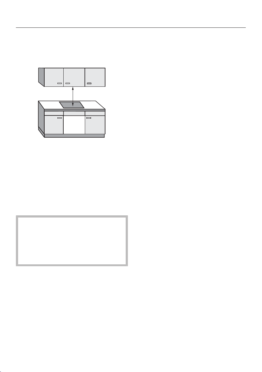
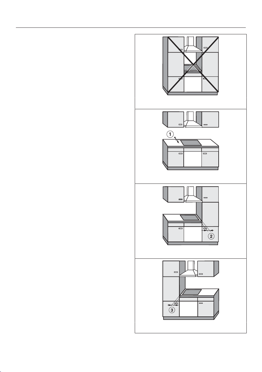
Safety distances
Safety distance above the SmartLine
element
The safety distance specified by the
manufacturer of the cooker hood must
be maintained between the SmartLine
element and the cooker hood above it.
If combustible objects are installed
above the SmartLine element (e.g. cab-
inets, utensil rail, etc.), a minimum
safety distance of 760mm must be
maintained.
When two or more SmartLine ele-
ments which have different safety
distances are installed together be-
low a cooker hood, you should ob-
serve the greatest specified safety
distance.
Installation
*INSTALLATION*
40
Safety distances to the sides and
back of the appliance
The SmartLine element should prefer-
ably be installed with plenty of space on
the right and left.
The minimum distance specified be-
low must be observed between the rear
of the SmartLine element and a tall unit
or room wall.
The minimum distance, specified
below must be adhered to between one
side of the SmartLine element (right or
left) and a tall unit or room wall. A min-
imum distance of 300mm must be ob-
served on the opposite side.
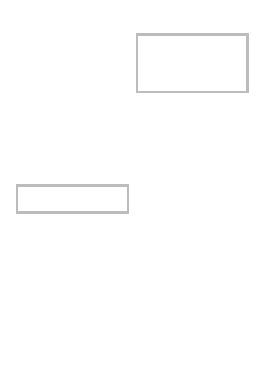
Minimum distance between the back
of the worktop cut-out and the rear
edge of the worktop:
50mm
Minimum distance on the right side
between the worktop cut-out and the
closest adjacent piece of furniture (e.g.
tall unit) or a room wall:
200mm.
Minimum distance on the left side
between the worktop cut-out and the
closest adjacent piece of furniture (e.g.
tall unit) or a room wall:
200mm.
Not allowed
Highly recommended
Not recommended
Not recommended
Installation
*INSTALLATION*
41
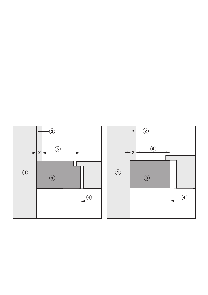
Safety distance when installing the appliance near a wall with additional
niche cladding
If a niche cladding is installed, a minimum safety distance must be maintained
between the worktop cut-out and the cladding, since high temperatures can dam-
age these materials.
If the niche cladding is made from a combustible material (e.g. wood) a minimum
safety distance of 50mm must be maintained between the worktop cut-out and
the cladding.
If the niche cladding is made from a non-combustible material (e.g. metal, natural
stone, ceramic tiles) the minimum safety distance between the worktop cut-out
and the cladding will be 50mm less the thickness of the cladding.
Example: 15mm niche cladding
50mm - 15mm = minimum safety distance of 35mm
Flush-fit installation Onset installation
a
Masonry
b
Niche cladding dimension x = thickness of the niche cladding material
c
Worktop
d
Worktop cut-out
e
Minimum distance to
combustible materials 50mm
non-combustible materials 50mm - dimension x
Installation
*INSTALLATION*
42
Installation notes –
surface-mounted
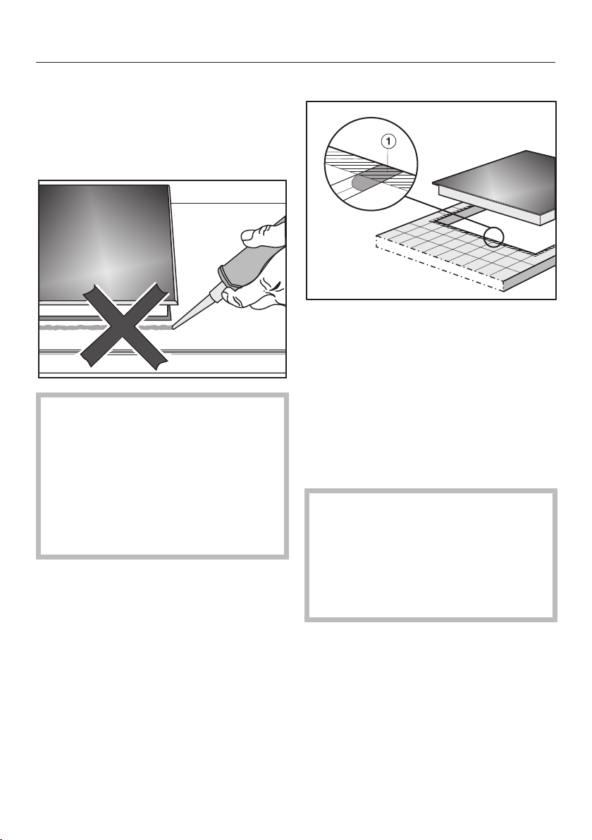
Sealing between the SmartLine Ele-
ment and the worktop
The SmartLine element and worktop
may be damaged if the element
needs to be removed after it has
been sealed with a sealant.
Do not use any sealant between the
SmartLine element and the worktop.
The seal under the edge of the top
part of the appliance provides a suf-
ficient seal for the worktop.
Tiled worktop
Grout lines and the hatched area un-
derneath the SmartLine element frame
must be smooth and even. If they are
not, the SmartLine element will not sit
flush with the worktop and the sealing
strip underneath the top part of the ap-
pliance will not provide a good seal
between the appliance and the work-
top.
Sealing strip
Dismantling the SmartLine element
for service purposes may damage
the sealing strip underneath the edge
of the SmartLine element.
Always replace the sealing strip be-
fore reinstalling the SmartLine ele-
ment.

Installation
*INSTALLATION*
43
Installing several
SmartLine elements
The gaps between the individual Smart-
Line elements are sealed with a silicone
sealant that is heat-resistant to at least
160°C. With flush-fit installation, the
gap between the SmartLine element(s)
and the worktop must also be sealed
with a silicone sealant that is heat-res-
istant to at least 160°C.
After installation, the SmartLine ele-
ments must be easily accessible from
below, so that the bottom half of the
casing can be removed for mainten-
ance. If the SmartLine elements are not
accessible from below, the sealant must
be removed so that they can be re-
moved.
Combination with a downdraft ex-
tractor
If the SmartLine element is installed in
combination with a downdraft extractor,
the latter must be installed first.
Installation
*INSTALLATION*
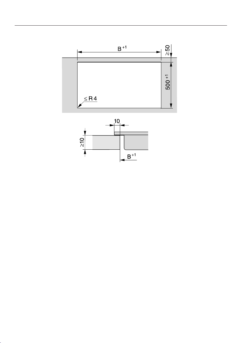
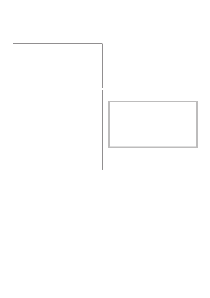
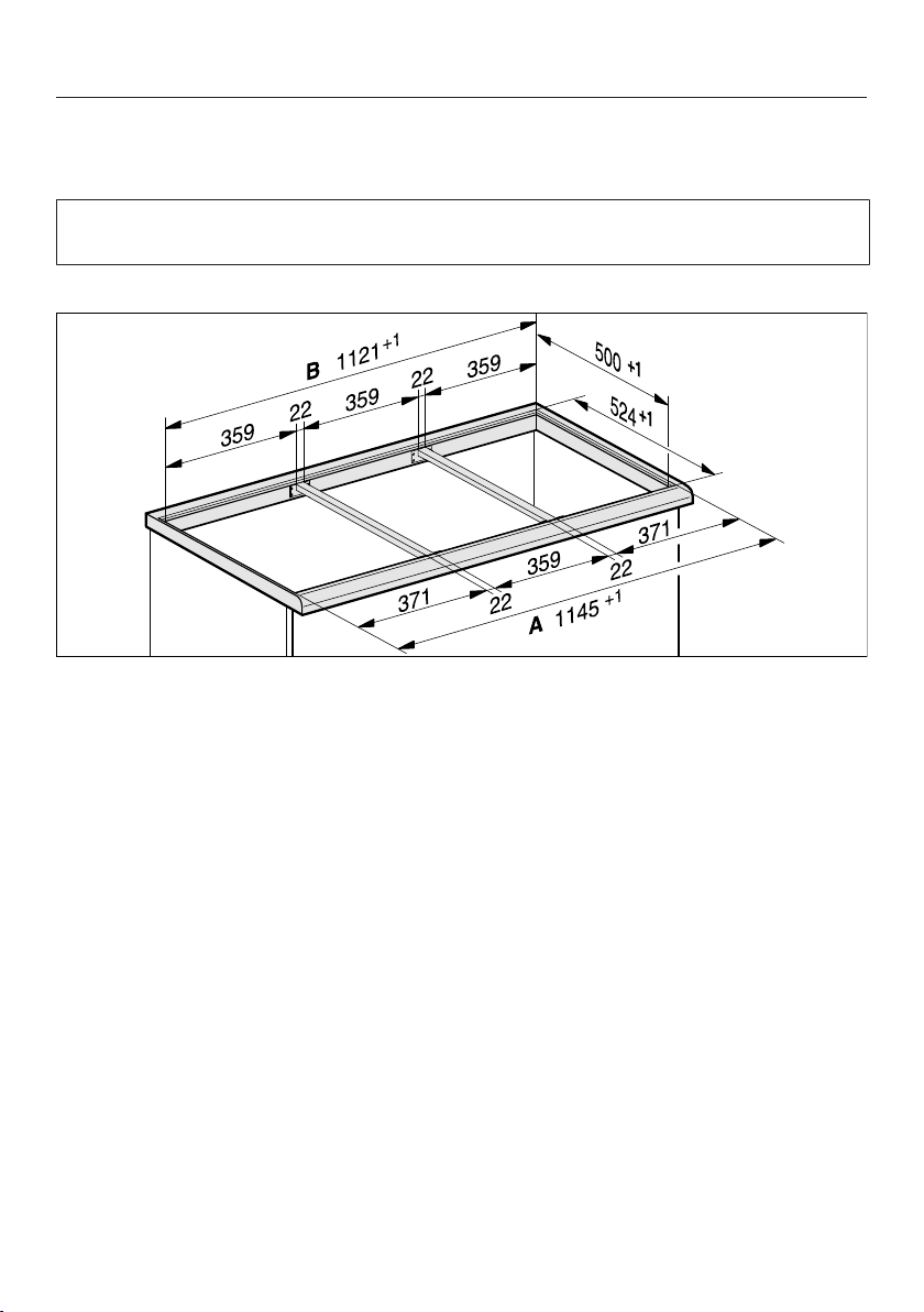
44
Worktop cutout – surface-mounted
Installation
*INSTALLATION*
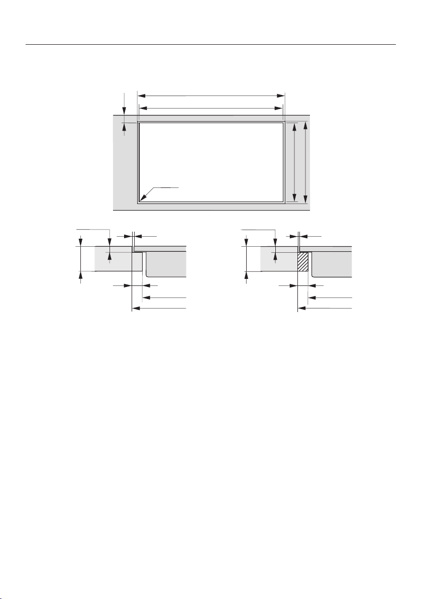
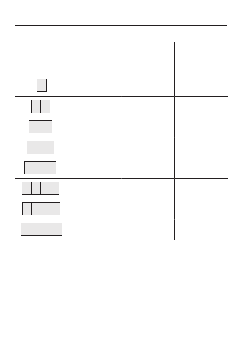
45
Installation with a countertop extractor
Combination examples Numberxwidth [mm] Dimen-
sionB
[mm]
Cooking ele-
ments
Countertop
extractor
1x378 1x120 481
2x378 1x120 862
1x378
1x620
2x120 1226
3x378 2x120 1365
2x378
1x620
2x120 1607
4x378 2x120 1746
1x620 2x120 845
Installation
*INSTALLATION*
46
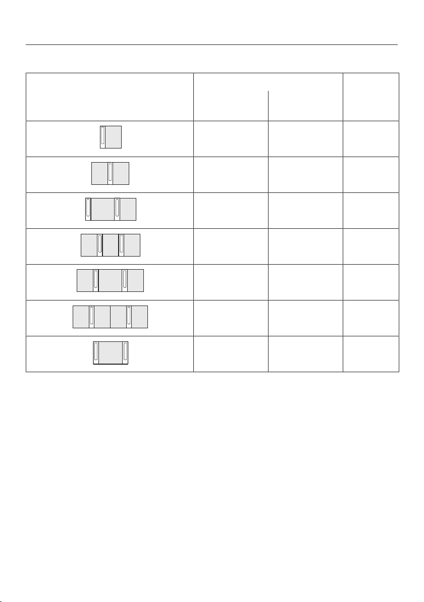
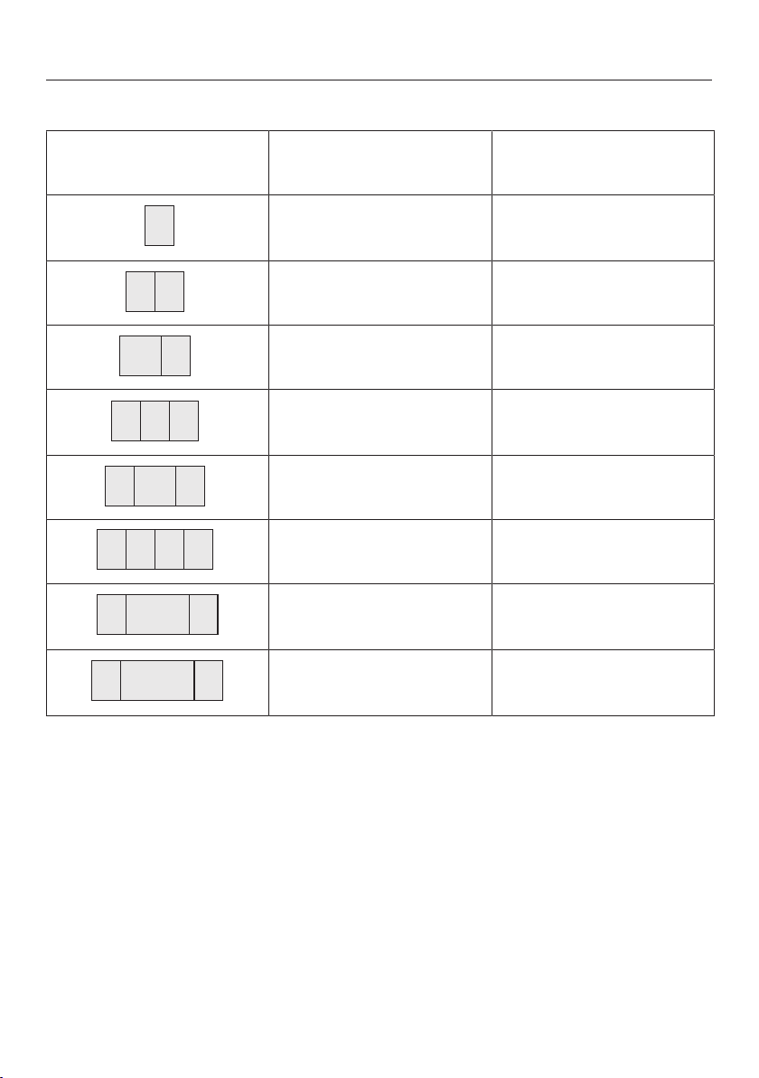
Installation without a countertop extractor
Combination examples Numberxwidth [mm] DimensionB
[mm]
Cooking elements
1x378 359
2x378 740
1x378
1x620
982
3x378 1121
2x378
1x620
1363
4x378 1502
2x378
1x800
1554
2x378
1x936
1680
Installation
*INSTALLATION*
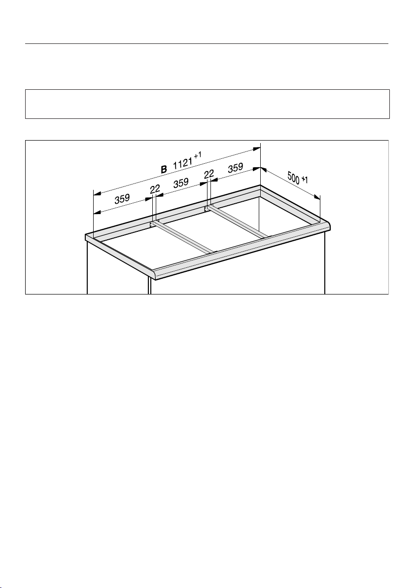
47
Spacer bars – surface-mounted
If you are installing several appliances, you must fit spacer bars between them.
The clips supplied with the spacer bars are only required for installing a
CSDA700xFL.
Installing 3elements and 2spacer bars

Installation
*INSTALLATION*
48
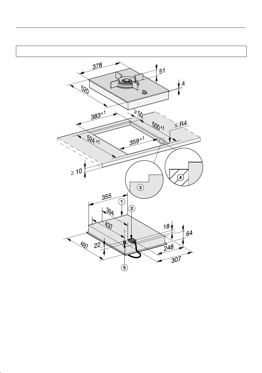
Installation dimensions–Surface-mounted
All dimensions are given in mm.
a
Front
b
Mains connection box with mains connection cable
Mains connection cable L=1440mm
c
Gas connection R½" ISO 7-1 (DIN EN 10226)
Installation
*INSTALLATION*
49
Installation – surface-mounted
Preparing the worktop
Create the worktop cutout. Remem-
ber to maintain the minimum safety
distances (see “Installation – Safety
distances”).
Seal any cut surfaces on wooden
worktops with a special varnish, sil-
icone sealant or resin to prevent the
wood from swelling as a result of
moisture ingress. The sealant must
be heat-resistant.
Make sure that the sealant does not
come into contact with the top of the
worktop.
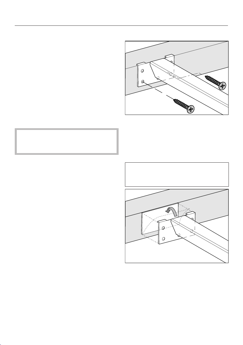
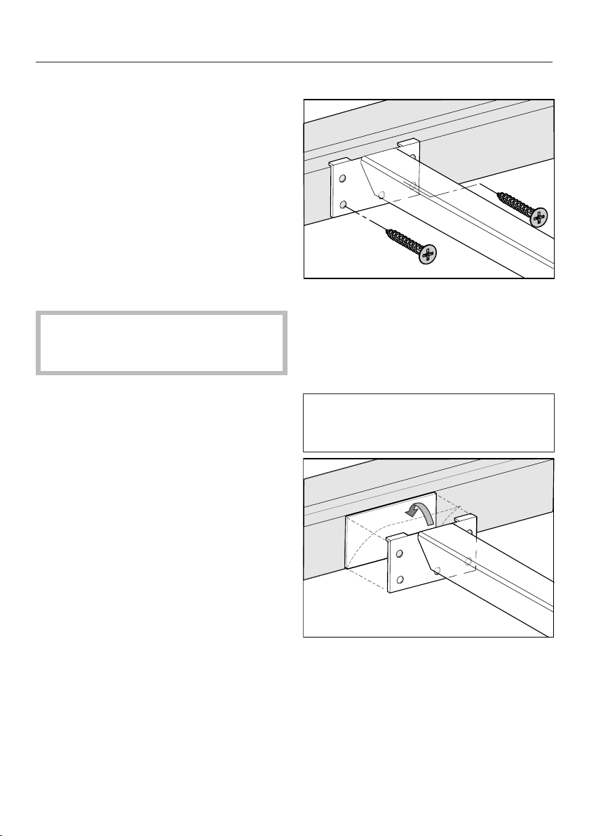
Fitting the spacer bars
Use the middle screw holes if one of the
following SmartLine elements is in-
stalled to the right or left of the spacer
bar: CS7611, CS 7641, CS7101(-1),
CS7102(-1)
Wooden worktops
Position the spacer bars flush onto
the upper edge of the cutout.
Secure the spacer bars with the
3.5x25mm wood screws supplied.
Natural stone worktops
You will need heavy-duty double-
sided tape (not supplied) to secure the
spacer bars.
Stick the tape along the top edge of
the worktop cutout.
Position the spacer bars flush onto
the upper edge of the cutout.
Press the spacer bars firmly into
place.
Installation
*INSTALLATION*
50
Installing the SmartLine element
Stick the supplied sealing strip under
the edge of the SmartLine element.
Do not apply the sealing strip under
tension.
Feed the mains connection cable
down through the worktop cutout.
Position the SmartLine element in the
worktop cutout. Ensure that:
- The seal of the appliance sits flush
with the worktop on all sides to en-
sure an effective seal all round.
- All gap widths are uniform.
If the seal does not meet the worktop
correctly on the corners, carefully
scribe the corner radii (≤R4) with a
jigsaw.
Do not use any additional sealant
(e.g. silicone) on the SmartLine ele-
ment.
Connect the SmartLine element to
the mains electricity supply.
If required, connect the SmartLine
element to the gas supply (see “In-
stallation – Gas connection”).
Check that the SmartLine element
works.
Seal the gaps between the individual
elements with a silicone sealant that
is heat-resistant to at least 160°C.
Unsuitable sealant can damage nat-
ural stone.
For natural stone worktops and nat-
ural stone tiles, only use silicone
sealant that is specially formulated
for natural stone. Follow the manu-
facturer’s instructions.
Checking operation
After installation, ignite all burners to
check that they are operating cor-
rectly:
- The flame must not go out on the
lowest setting, or when the control is
turned quickly from the highest to the
lowest setting.
- On the highest setting, the flame
must have a distinctive and visible
core.
Installation
*INSTALLATION*
51
Installation notes –
flush-fit
Flush-fit installation is only possible in
natural stone (granite, marble), solid
wood and tiled worktops. For installa-
tion in worktops made of other materi-
als, please consult the relevant manu-
facturer as to whether their worktops
are suitable for flush-fit installation.
The internal width of the base unit un-
derneath the appliance must be at
least as wide as the inner worktop
cutout (see “Installation – Building-in
dimensions – flush-fit”), so that the
SmartLine element is easily accessible
from underneath after installation and
the bottom half of the casing can be
removed for maintenance. If the ele-
ment is not freely accessible from be-
low after installation, the sealant must
be removed so that the element can
be removed.
Natural stone worktops
The SmartLine element is set directly in
the cutout.
Solid wood worktops, tiled worktops,
glass worktops
The SmartLine element is set on a
wooden frame inside the cutout. The
frame must be provided on site, and is
not supplied with the appliance.
Sealing strip
Dismantling the SmartLine element
for service purposes may damage
the sealing strip underneath the edge
of the SmartLine element.
Always replace the sealing strip be-
fore reinstalling the SmartLine ele-
ment.

Installation
*INSTALLATION*
52
Installing several
SmartLine elements
The gaps between the individual Smart-
Line elements are sealed with a silicone
sealant that is heat-resistant to at least
160°C. With flush-fit installation, the
gap between the SmartLine element(s)
and the worktop must also be sealed
with a silicone sealant that is heat-res-
istant to at least 160°C.
After installation, the SmartLine ele-
ments must be easily accessible from
below, so that the bottom half of the
casing can be removed for mainten-
ance. If the SmartLine elements are not
accessible from below, the sealant must
be removed so that they can be re-
moved.
Combination with a downdraft ex-
tractor
If the SmartLine element is installed in
combination with a downdraft extractor,
the latter must be installed first.
Installation
*INSTALLATION*
53
Worktop cutout – flush-fit
B
0
50
A
524
500
+
1
+ 1
ß R 4
B
A
0
2
12
0
10
5,5
+
0,5
*
/ 7
+ 0,5
0
2
12
0
10
5,5
+
0,5
*
/ 7
+ 0,5
+ 1
+ 1
+ 1
+ 1
B
A
+ 1
+ 1
Natural stone worktop Wooden worktop
* 7
+
0.5
mm with CS7611FL
Installation
*INSTALLATION*
54
Installation with a countertop extractor
Combination examples Numberxwidth [mm] Dimen-
sionA
[mm]
Dimen-
sionB
[mm]
Cooking ele-
ments
Counter-
top ex-
tractor
1x378 1x120 505 481
2x378 1x120 886 862
1x378
1x620
2x120 1250 1226
3x378 2x120 1389 1365
2x378
1x620
2x120 1631 1607
4x378 2x120 1770 1746
1x620 2x120 869 845
Installation
*INSTALLATION*
55
Installation without a countertop extractor
Combination ex-
amples
Numberxwidth
[mm]
DimensionA
[mm]
DimensionB
[mm]
Cooking elements
1x378 383 359
2x378 764 740
1x378
1x620
1006 982
3x378 1145 1121
2x378
1x620
1387 1363
4x378 1526 1502
2x378
1x800
1567 1543
2x378
1x936
1703 1679
Installation
*INSTALLATION*
56
Spacer bars – flush-fit
If you are installing several appliances, you must fit spacer bars between them.
The clips supplied with the spacer bars are only required for installing a
CSDA700xFL.
Installing 3elements and 2spacer bars
Installation
*INSTALLATION*
57
Installation dimensions–Flush-fit
All dimensions are given in mm.
a
Front
b
Mains connection box with mains connection cable
Mains connection cable L=1440mm
c
Stepped cutout (for detailed illustrations, see “Installation – Worktop cutout –
flush-fit”)
d
12mm wooden frame (not supplied, for detailed illustrations, see “Installation –
Worktop cutout – flush-fit”)
e
Gas connection R½" ISO 7-1 (DIN EN 10226)
Installation
*INSTALLATION*
58
Installation – flush-fit
Preparing the worktop
Create the worktop cutout. Remem-
ber to maintain the minimum safety
distances (see “Installation – Safety
distances”).
Seal any cut surfaces on wooden
worktops with a special varnish, sil-
icone sealant or resin to prevent the
wood from swelling as a result of
moisture ingress. The sealant must
be heat-resistant.
Make sure that the sealant does not
come into contact with the top of the
worktop.
For wooden worktops, secure the
wooden frame 5.5mm below the up-
per edge of the worktop.
For CS7611FL, the wooden frame
must be secured 7mm under the up-
per edge of the worktop.
Fitting the spacer bars
Use the middle screw holes if one of the
following SmartLine elements is in-
stalled to the right or left of the spacer
bar: CS7611, CS 7641, CS7101(-1),
CS7102(-1)
Wooden worktops
Position the spacer bars flush onto
the lower step of the stepped cutout.
Secure the spacer bars with the
3.5x25mm wood screws supplied.
Natural stone worktops
You will need heavy-duty double-
sided tape (not supplied) to secure the
spacer bars.
Stick the tape onto the lower step of
the stepped cutout.
Position the spacer bars flush onto
the lower step of the stepped cutout.
Press the spacer bars firmly into
place.
Installation
*INSTALLATION*
59
Installing the SmartLine element
Stick the supplied sealing strip under
the edge of the SmartLine element.
Do not apply the sealing strip under
tension.
Feed the mains connection cable
down through the worktop cutout.
Position the SmartLine element in the
worktop cutout. Ensure that:
- The seal of the appliance sits flush
with the worktop on all sides to en-
sure an effective seal all round.
- All gap widths are uniform.
Connect the SmartLine element to
the mains electricity supply.
If required, connect the SmartLine
element to the gas supply (see “In-
stallation – Gas connection”).
Check that the SmartLine element
works.
Seal the gaps between the individual
elements and between the elements
and the worktop with a silicone seal-
ant that is heat-resistant to at least
160°C.
Unsuitable sealant can damage nat-
ural stone.
For natural stone worktops and nat-
ural stone tiles, only use silicone
sealant that is specially formulated
for natural stone. Follow the manu-
facturer’s instructions.
Checking operation
After installation, ignite all burners to
check that they are operating cor-
rectly:
- The flame must not go out on the
lowest setting, or when the control is
turned quickly from the highest to the
lowest setting.
- On the highest setting, the flame
must have a distinctive and visible
core.
Installation
*INSTALLATION*
60
Gas connection
For any gas work in the UK always
use a Gas Safe registered engineer.
Risk of explosion due to an in-
correct gas connection.
If the gas connection is carried out
incorrectly, it may result in gas leak-
age.
Connection to the gas supply must
only be undertaken by an approved
and registered gas installer (GasSafe
in the UK) in strict accordance with
current local and national safety and
building regulations. The installer is
responsible for ensuring that the ap-
pliance functions correctly when in-
stalled.
Risk of explosion due to an in-
correct conversion.
If the conversion to another type of
gas is carried out incorrectly, it may
result in gas leakage.
Conversion from one type of gas to
another must only be undertaken by
an approved and registered gas in-
staller in strict accordance with cur-
rent local and national safety and
building regulations (GasSafe in the
UK). The installer is responsible for
ensuring that the appliance functions
correctly when installed.
The gas connection must be in-
stalled so that connection can be
made either from inside or outside
the kitchen furniture unit. The isolat-
ing valve must be easily accessible
and visible (by opening the cabinet
door if necessary).
Check with your local gas supplier
about the type of gas supplied and
compare this information with the
type of gas quoted on the appli-
ance's data plate.
The hob is not connected to an ex-
haust flue.
When installing and connecting the
appliance please observe all relevant
installation instructions and ensure it
has adequate ventilation once in-
stalled.
The gas connection must be made in
accordance with national and local
regulations (GasSafe in the UK).
Any special local conditions relating
to gas installations as well as build-
ing regulations must also be ob-
served.
Installation
*INSTALLATION*
61
Risk of heat damage.
Gas connections, pipes and connec-
tion cables can suffer damage if ex-
posed to heat from the hob.
After installation make sure that
neither the gas pipe nor the mains
cable can come into contact with hot
parts of the appliance and that the
gas pipe and connections on the hob
cannot come into contact with hot
gas exhaust.
Risk of explosion due to dam-
aged gas pipes.
Gas can leak from damaged flexible
gas pipes.
Attach flexible gas pipes in such a
way so that they do not come into
contact with any moving kitchen
parts (e.g. a drawer) and are not ex-
posed to mechanical stress.
Connect the hob to the gas supply in
accordance with national and local
regulations. Check the gas connec-
tion for any leaks.
This hob is a class 3 appliance and is
suitable for use with natural gas or li-
quid gas.
Category in acc. with EN 30
United Kingdom, Ireland
II2H3+ 20, 28–30/37mbar
Depending on country of destination
this appliance is set up for connection
to natural or liquid gas. See adhesive la-
bel on the appliance.
Depending on country of destination,
jets are supplied for conversion to a dif-
ferent type of gas. If the appropriate jets
have not been supplied with the appli-
ance, you will need to contact Miele.
Conversion to another type of gas is
described in the section “Converting to
another type of gas”.
Connecting the hob
The hob is supplied with a conical ¹/₂"
gas connection point. There are two
connection options:
- Fixed connection
- Flexible connection in accordance
with DIN 3383 Part 1, maximum
length 2000 mm. (Not for the UK.)
Risk of explosion due to gas
leakage.
Unsuitable sealant will not ensure the
required leak protection for connec-
tions.
Ensure that a suitable sealant is
used.
Installation
*INSTALLATION*
62
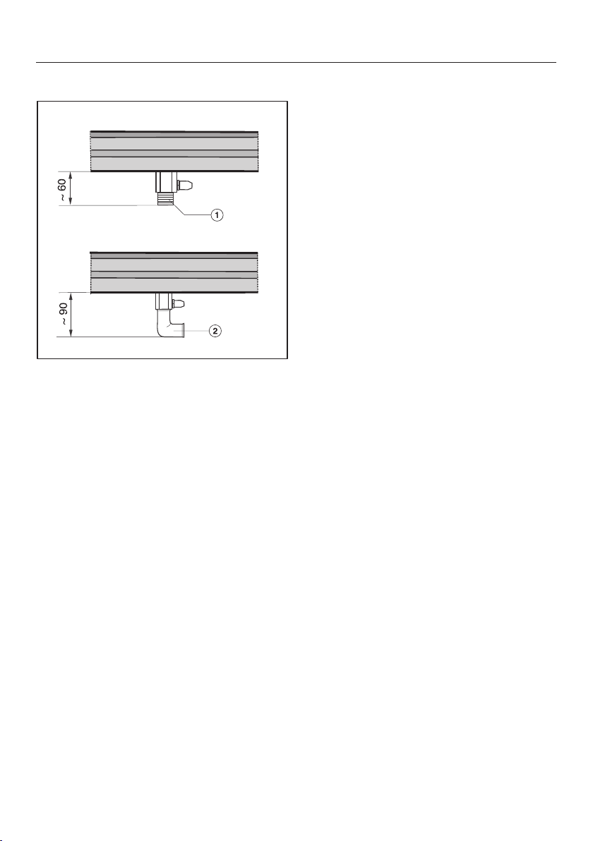
Using a 90° angle
a
Connection R¹/₂" with test point -
ISO7-1 (DINEN10226)
b
90° elbow
The installation height in the area of
the gas connection is increased to
approx. 90mm.
Installation
*INSTALLATION*
63
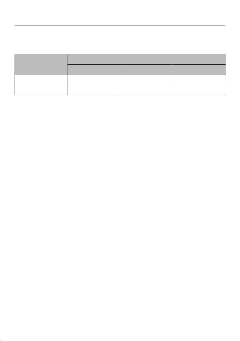
Burner ratings
Nominal ratings
Gas type Highest setting Lowest setting
kW g/h kW
Natural gas H 4.5 – 0.3
Liquid gas 4.2 306 0.3
Installation
*INSTALLATION*
64
Electrical connection
The SmartLine element is supplied with
a mains cable with moulded plug ready
for connection to a suitable earthed
socket.
The socket must be easily accessible
after the SmartLine element has been
installed. If the socket is not easily ac-
cessible, ensure that a suitable means
of disconnection is provided on the in-
stallation side for each pole.
Risk of fire from overheating.
Connecting the SmartLine element to
multi-socket adapters or extension
cables can overload the cables.
For safety reasons, do not use an ex-
tension cable or multi-socket ad-
apter.
The electrical installation must comply
with BS7671 requirements.
For safety reasons, we recommend us-
ing a type residual current device
(RCD) in the relevant electrical installa-
tion for connecting the SmartLine ele-
ment.
If the mains connection cable is dam-
aged, it must only be replaced with a
specific mains connection cable of the
same type (available from the Miele
Customer Service Department). For
safety reasons, such replacement may
only be carried out by a qualified spe-
cialist or the Miele Customer Service
Department.
These operating instructions and the
data plate indicate the nominal power
consumption and the appropriate fuse
rating. Compare this information with
the data of the on-site electrical con-
nection.
If in any doubt, consult a qualified elec-
trician.
Temporary or permanent operation on
an autonomous power supply system or
a power supply system that is not syn-
chronised with the mains power supply
(e.g. island networks, back-up systems)
is possible. A prerequisite for operation
is that the power supply system com-
plies with the specifications of
EN50160 or an equivalent standard.
The function and operation of the pro-
tective measures provided in the do-
mestic electrical installation and in this
Miele product must also be maintained
in isolated operation or in operation that
is not synchronised with the mains
power supply, or these measures must
be replaced by equivalent measures in
the installation. As described, for ex-
ample, in the current version of BS OH-
SAS 18001–2 ISO 45001.
Converting to another gas type
*INSTALLATION*
65
Risk of explosion due to an in-
correct conversion.
If the conversion to another type of
gas is carried out incorrectly, it may
result in gas leakage.
Conversion from one type of gas to
another must only be undertaken by
an approved and registered gas in-
staller in strict accordance with cur-
rent local and national safety and
building regulations (GasSafe in the
UK). The installer is responsible for
ensuring that the appliance functions
correctly when installed.
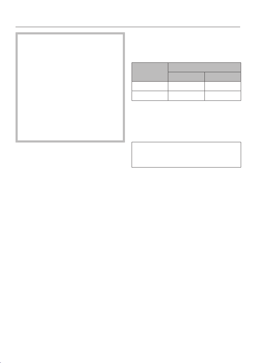
Jet table
The jet markings refer to a ¹/₁₀₀mm
bore diameter.
Gas type
Main jet Small jet
Natural gas H 2x 1.04/0.72 0.88/0.42
Liquid gas 2x 0.66/0.46 0.52/0.23
Changing the jets
Disconnect the hob from the electri-
city supply and turn off the gas sup-
ply.
When converting to another type of
gas, both the main and small jets
need to be changed.
Converting to another gas type
*INSTALLATION*
66
Changing the main jets
Remove the burner caps and
burner head.
Using an M7 socket spanner, un-
screw the main jets.
Fit the correct jets securely (see jet
table).
Secure the jets against inadvertent
loosening with sealing wax.
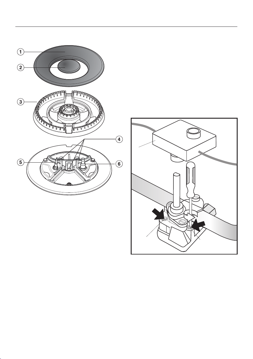
Changing the small jets
Remove the burner components.
Unscrew the fixing screws from the
burner.
Pull the rotary control off.
Loosen the fixing nuts/screws (de-
pending on the model) on the under-
side.
Carefully remove the base.
a
c
b
a
Ignition switch
b
Small jet with smaller diameter
c
Small jet with larger diameter
Remove the ignition switch.
Using a small screwdriver, unscrew
the two small jets in the gas fit-
ting.
Pull out the jets with a pair of pointed
pliers.

Converting to another gas type
*INSTALLATION*
67
Fit the correct jets securely (see jet
table).
Secure the jets against inadvertent
loosening with sealing wax.
Functional check
Check all gas fittings for leaks.
Reassemble the hob.
Ignite all burners to check that they
are operating correctly.
- The flame must not go out on the
lowest setting, or when the control is
turned quickly from the highest to the
lowest setting.
- On the highest setting, the flame
must have a distinctive and visible
core.
Adhere the label supplied with the
jets, stating the type of gas being
used.
Product data sheets
68
The following data sheets apply to the models described in this operating instruc-
tion manual.
Information for domestic gas-fired hobs
In acc. with regulation (EU) No. 66/2014
MIELE
Model name/identifier CS 7101-1
Number of gas burners 1
Energy efficiency per gas burner (EE
gas burner
) 1. = 55,8
Energy efficiency for the gas hob calculated per kg
(EE
gas hob
)
55,8


United Kingdom
Miele Co. Ltd., Fairacres, Marcham Road, Abingdon, Oxon, OX14 1TW
Tel: 0330 160 6600, Internet: www.miele.co.uk/service, E-mail: [email protected]
Australia
Miele Australia Pty. Ltd.
ACN 005 635 398
ABN 96 005 635 398
1 Gilbert Park Drive
Knoxfield, VIC 3180
Tel: 1300 464 353
Internet: www.miele.com.au
Miele Electrical Appliances Co., Ltd.
1-3 Floor, No. 82 Shi Men Yi Road
Jing' an District
200040 Shanghai, PRC
Tel: +86 21 6157 3500
Fax: +86 21 6157 3511
E-mail: [email protected],
Internet: www.miele.cn
China Mainland
Miele (Hong Kong) Ltd.
41/F - 4101, Manhattan Place
23 Wang Tai Road
Kowloon Bay, Hong Kong
Tel: (852) 2610 1025
Fax: (852) 3579 1404
Email:
Website: www.miele.hk
Hong Kong, China
Miele India Pvt. Ltd.
1st Floor, Copia Corporate Suites,
Commercial Plot 9,
Mathura Road, Jasola,
New Delhi - 110025
E-mail: customercare@miele.in
Website: www.miele.in
India
Miele Ireland Ltd.
2024 Bianconi Avenue
Citywest Business Campus
Dublin 24
Tel: (01) 461 07 10
Fax: (01) 461 07 97
E-Mail: [email protected]
Internet: www.miele.ie
Ireland
Malaysia
Miele Sdn Bhd
Suite 12-2, Level 12
Menara Sapura Kencana
Petroleum
Solaris Dutamas No. 1
Jalan Dutamas 1
50480 Kuala Lumpur, Malaysia
Phone: +603-6209-0288
Fax: +603-6205-3768
Miele New Zealand Limited
IRD 98 463 631
8 College Hill
Freemans Bay, Auckland 1011
New Zealand
Tel: 0800 464 353
Internet: www.miele.co.nz
New Zealand
Miele Pte. Ltd.
29 Media Circle
#11-04 ALICE@Mediapolis
Singapore 138565
sTel: +65 6735 1191
Fax: +65 6735 1161
E-Mail: [email protected]
Internet: www.miele.sg
Singapore
Miele (Pty) Ltd.
63 Peter Place
Bryanston 2194
P.O. Box 69434
Bryanston 2021
Tel: (011) 875 9000
Fax: (011) 875 9035
E-mail: [email protected]
Internet: www.miele.co.za
South Africa
Miele Appliances Ltd.
Showroom 1
Eiffel 1 Building
P.O. Box 114782 - Dubai
Tel. +971 4 3044 999
Fax. +971 4 3418 852
800-MIELE (64353)
E-Mail: [email protected]
Website: www.miele.ae
United Arab Emirates
Manufacturer:
Miele & Cie. KG, Carl-Miele-Straße 29, 33332 Gütersloh, Germany
Thailand
Miele Appliances Ltd.
BHIRAJ TOWER at EmQuartier
43rd Floor Unit 4301-4303
689 Sukhumvit Road
North Klongton Sub-District
Vadhana District
Bangkok 10110, Thailand
Sheikh Zayed Road, Umm Al Sheif

M.-Nr. 11 503 470 / 03en-GB
CS7101-1