
Owner’s Manual
2022
2022
CRF1100A/D/A4/D4

This manual should be considered a permanent part of the vehicle and
should remain with the vehicle when it is resold.
This publication includes the latest production information available before
printing. Honda Motor Co., Ltd. reserves the right to make changes at any
time without notice and without incurring any obligation.
No part of this publication may be reproduced without written permission.
The vehicle pictured in this owner’s manual may not match your actual
vehicle.
CRF1100D is USA model only.
© 2021 Honda Motor Co., Ltd.

Welcome
Congratulations on your purchase of a new
Honda vehicle. Your selection of a Honda
makes you part of a worldwide family of
satisfied customers who appreciate Honda's
reputation for building quality into every
product.
To ensure your safety and riding pleasure:
● Read this owner's manual carefully.
● Follow all recommendations and
procedures contained in this manual.
● Pay close attention to safety messages
contained in this manual and on the vehicle.
To protect your investment, we urge you to
take responsibility for keeping your vehicle
well-serviced and maintained. Also, observe
the break-in guidelines and always perform
the pre-ride inspection and other periodic
checks in this manual.
When service is required, remember that your
Honda dealer knows your vehicle best. If you
have the required mechanical “know-how”
and tools, you can purchase an official Honda
Service Manual to help you perform many
maintenance and repair tasks.
2 P. 359
Read the warranty information thoroughly so
that you understand the warranty coverage
and are aware of your rights and
responsibilities.
2 P. 360
You may also want to visit our website at
www.powersports.honda.com.
www.honda.ca.
Happy riding!
Canada

A Few Words About Safety
Your safety, and the safety of others, is very
important. Operating this vehicle safely is an
important responsibility.
To help you make informed decisions about
safety, we have provided operating
procedures and other information on safety
labels and in this manual. This information
alerts you to potential hazards that could hurt
you or others.
Of course, it is not practical or possible to
warn you about all hazards associated with
operating or maintaining a vehicle. You must
use your own good judgment.
You will find important safety information in a
variety of forms, including:
● Safety labels on the vehicle
●
Safety Messages preceded by a safety alert
symbol and one of three signal words:
DANGER, WARNING, or CAUTION.
These signal words mean:
3
DANGER
You WILL be KILLED or SERIOUSLY HURT
if you don’t follow instructions.
3
WARNING
You CAN be KILLED or SERIOUSLY HURT
if you don’t follow instructions.
3
CAUTION
You CAN be HURT if you don’t follow
instructions.
Other important information is provided
under the following titles:
NOTICE
Information to help you avoid
damage to your vehicle, other
property, or the environment.


Vehicle Safety
This section contains important information for safe riding of your vehicle.
Please read this section carefully.
Safety Guidelines .......................................... P. 3
Safety Labels.................................................. P. 8
Safety Precautions ...................................... P. 10
Riding Precautions...................................... P. 11
Accessories & Modifications...................... P. 15
Off-Road Safety .......................................... P. 16
Loading ........................................................ P. 17

Safety Guidelines
3
Continued
Vehicle Safety
Safety Guidelines
Follow these guidelines to enhance your safety:
● Perform all routine and regular inspections
specified in this manual.
● Stop the engine and keep sparks and flames
away before filling the fuel tank.
● Do not run the engine in enclosed or partly
enclosed areas. Carbon monoxide in exhaust
gases is toxic and can kill you.
It's a proven fact: helmets and protective apparel
significantly reduce the number and severity of
head and other injuries. So always wear an
approved helmet and protective apparel.
2 P. 10
Make sure that you are physically fit, mentally
focused and free of alcohol and drugs. Check
that you and your passenger are both wearing
an approved helmet and protective apparel.
Instruct your passenger on holding onto the
grab rail or your waist, leaning with you in turns,
and keeping their feet on the footpegs, even
when the vehicle is stopped.
Even if you have ridden other vehicles, practice
riding in a safe area to become familiar with how
this vehicle works and handles, and to become
accustomed to the vehicle's size and weight.
Always Wear a Helmet
Before Riding
Take Time to Learn & Practice

Safety Guidelines
4
Vehicle Safety
We recommend that all riders take a certified
course approved by the Motorcycle Safety
Foundation (MSF) or a state approved training
course. New riders should start with the basic
course, and even experienced riders will find the
advanced course beneficial.
For information about the MSF training course
nearest you, call the national toll-free number:
(800) 446-9227.
Other riding tips can be found in the You
and Your Motorcycle Riding Tips booklet that
came with your vehicle.
Developing off-road riding skill is a gradual step-
by step process. Start by practicing at low speeds
in a safe area and slowly build your skills.
Ask your dealer if there are off-road riding
groups in your area where you can learn from
experienced riders. Also be sure to read Tips &
Practice Guide for the Off-Highway Motorcyclist
that came with your new vehicle.
Always pay attention to other vehicles around
you, and do not assume that other drivers see
you. Be prepared to stop quickly or perform an
evasive maneuver.
Make yourself more visible, especially at night, by
wearing bright reflective clothing, positioning
yourself so other drivers can see you, signaling
before turning or changing lanes, and using your
horn when necessary.
The terrain can be present a variety of challenges
when you ride off-road.
Continually “read” the terrain for unexpected
turns, drop-offs, rocks, ruts and other hazards.
Always keep your speed low enough to allow
time to see and react to hazards.
USA
Ride Defensively
Make Yourself Easy to See
Be Alert for Off-road Hazards

Safety Guidelines
5
Continued
Vehicle Safety
Never ride beyond your personal abilities or
faster than conditions warrant. Fatigue and
inattention can impair your ability to use good
judgment and ride safely.
Alcohol or drugs and riding don't mix. Even one
alcoholic drink can reduce your ability to
respond to changing conditions, and your
reaction time gets worse with every additional
drink. The same is true for drug use. Don't drink
or use and ride, and don't let your friends do it
either.
It's important to keep your vehicle properly
maintained and in safe riding condition.
Having a breakdown can be difficult, especially if
you are stranded off-road far from your base.
Inspect your vehicle before every ride and
perform all recommended maintenance. Never
exceed load limits (
2 P. 17), and do not modify
your vehicle or install accessories that would
make your vehicle unsafe (
2 P. 15).
Personal safety is your first priority. If you or
anyone else has been injured, take time to assess
the severity of the injuries and whether it is safe
to continue riding. Call for emergency assistance
if needed. Also follow applicable laws and
regulations if another person or vehicle is
involved in the crash.
If you decide to continue riding, first turn the
ignition switch to the OFF position, and evaluate
the condition of your vehicle. Inspect for fluid
leaks, check the tightness of critical nuts and
bolts, and check the handlebar, control levers,
brakes, and wheels. Ride slowly and cautiously.
Your vehicle may have suffered damage that is
not immediately apparent. Have your vehicle
thoroughly checked at a qualified service facility
as soon as possible.
Ride within Your Limits
Don't Drink or Use Drugs and Ride
Keep Your Honda in Safe Condition
If You are Involved in a Crash
Safety Guidelines
6
Vehicle Safety
If you smell an unusual odor coming from the
lithium-ion (li-ion) battery, park your vehicle in a
safe place outside and away from flammable
objects, then turn the ignition switch to the OFF
position. Have your vehicle inspected by your
dealer immediately.
Unlike standard motorcycles, or its manual
transmission sibling, the CRF1100D and
CRF1100D4 with dual-clutch transmission does
not have a clutch lever that would provide you
with an additional means to control the engine
power being transmitted to the rear wheel. Thus,
in the unlikely event that you experience a stuck
throttle or other unintended application of
power to the rear wheel, you should shut down
the engine by use of the engine stop switch
(
2 P. 115). By moving this switch to the (Stop)
position, you will immediately stop the engine
but maintain all electrical system functions,
including lights and indicators.
Lithium-Ion (Li-Ion) Battery Emergency Shut-down Procedure for
Vehicles Equipped with Dual Clutch
Transmission
CRF1100D/D4

Safety Guidelines
7
Vehicle Safety
Exhaust contains poisonous carbon monoxide, a
colorless, odorless gas. Breathing carbon
monoxide can cause loss of consciousness and
may lead to death.
If you run the engine in a confined or even partly
enclosed area, the air you breathe could contain
a dangerous amount of carbon monoxide.
Never run your vehicle inside a garage or other
enclosure.
Carbon Monoxide Hazard
3
WARNING
Running the engine of your vehicle while
in an enclosed or even partially enclosed
area can cause a rapid build-up of toxic
carbon monoxide gas.
Breathing this colorless, odorless gas can
quickly cause unconsciousness and lead
to death.
Only run your vehicle's engine when it is
located in a well ventilated area
outdoors.
Safety Labels
8
Vehicle Safety
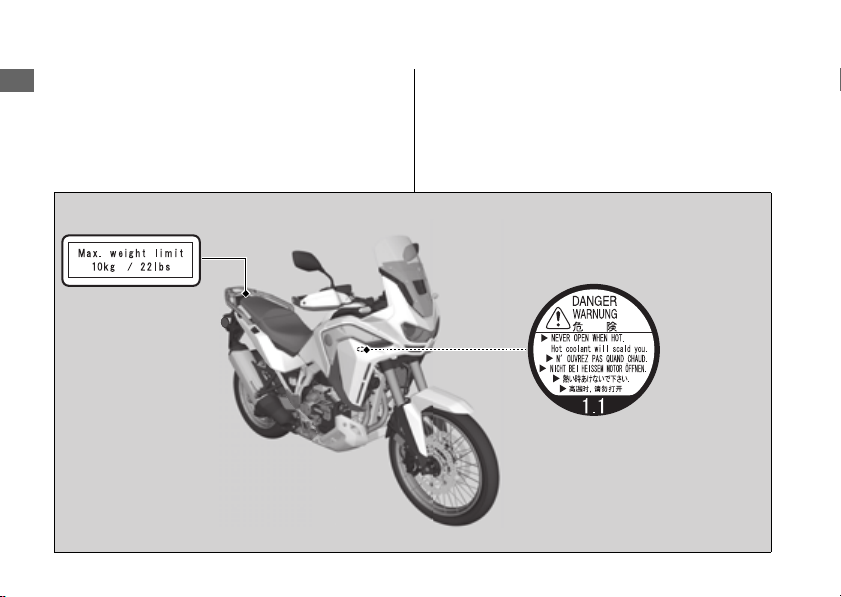
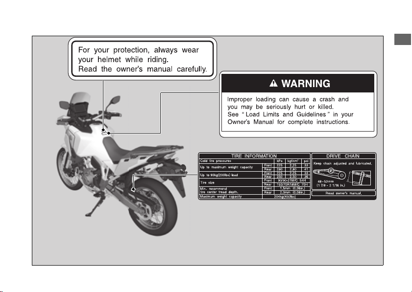
Safety Labels
Safety and information labels on your vehicle
provide important safety information and may
warn you of potential hazards that could cause
serious injury. Read these labels carefully and
don't remove them.
If a label comes off or becomes hard to read,
contact your dealer for a replacement.
Safety Labels
9
Vehicle Safety
Safety Precautions
10
Vehicle Safety
Safety Precautions
● Ride cautiously and keep your hands on the
handlebar and feet on the footpegs.
● Instruct your passenger to keep their hands on
the seat strap or your waist and their feet on
the footpegs while riding.
● Always consider the safety of your passenger,
as well as other drivers and riders.
Make sure that you and any passenger are
wearing an approved helmet, eye protection,
and high-visibility protective clothing. Avoid
wearing loose clothes that could get caught on
any part of the vehicle. Ride defensively in
response to weather and road conditions.
#
Helmet
Should be safety-standard certified, high-
visibility, and the correct size for your head.
● Must fit comfortably but securely, with the chin
strap fastened
● Face shield with unobstructed field of vision or
other approved eye protection
Look for a DOT (Department of
Transportation) certification label on any helmet
you buy.
#
Gloves
Full-finger leather gloves with high abrasion
resistance
Protective Apparel
3
WARNING
Not wearing a helmet increases the
chance of serious injury or death in a
crash.
Make sure that you and any passenger
always wear an approved helmet and
protective apparel.
USA

Riding Precautions
11
Continued
Vehicle Safety
#
Boots or Riding Shoes
Sturdy boots with non-slip soles and ankle
protection
#
Jacket and Pants
Protective, highly visible, long-sleeved jacket and
durable long pants for riding (or a protective suit)
#
Additional Off-road Gear
On-road apparel may also be suitable for casual
off-road riding. But if you plan on any serious
off-road riding you will need more serious off-
road gear. In addition to your helmet and eye
protection, we recommend off-road motorcycle
boots and gloves, riding pants with knee and hip
pads, a jersey with elbow pads, and a chest/
shoulder protector.
Riding Precautions
During the first 300 miles (500 km) of running,
follow these guidelines to ensure your vehicle's
future reliability and performance.
● Avoid full-throttle starts and rapid
acceleration.
● Avoid hard braking and rapid down-shifts.
● Ride conservatively.
Observe the following guidelines:
● Avoid excessively hard braking and
downshifting.
u Sudden braking can reduce the vehicle's
stability.
u Where possible, reduce speed before
turning; otherwise you risk sliding out.
Break-in Period
Brakes

Riding Precautions
12
Vehicle Safety
● Exercise caution on low traction surfaces.
u The tires slip more easily on such surfaces
and braking distances are longer.
● Avoid continuous braking.
u Repeated braking, such as when
descending long, steep slopes can seriously
overheat the brakes, reducing their
effectiveness. Use engine braking with
intermittent use of the brakes to reduce
speed.
● For full braking effectiveness, operate both the
front and rear brakes together.
#
Anti-lock Brake System (ABS)
This model is equipped with an Anti-lock Brake
System (ABS) designed to help prevent the
brakes from locking up during hard braking.
The ABS functions with information provided by
the IMU (Inertia Measurement Unit).
● ABS does not reduce braking distance. In
certain circumstances, ABS may result in a
longer stopping distance.
● ABS does not function at speeds below 6 mph
(10 km/h).
● The brake lever and pedal may recoil slightly
when applying the brakes. This is normal.
● Always use the recommended front/rear tires
and sprockets to ensure correct ABS
operation.
#
Engine Braking
Engine braking helps slow your vehicle down
when you release the throttle. For further slowing
action, downshift to a lower gear. Use engine
braking with intermittent use of the brakes to
reduce speed when descending long, steep
slopes.
#
Wet or Rainy Conditions
Road surfaces are slippery when wet, and wet
brakes further reduce braking efficiency.
Exercise extra caution when braking in wet
conditions.
If the brakes get wet, apply the brakes while
riding at low speed to help them dry.

Riding Precautions
13
Continued
Vehicle Safety
● Park on a firm, level surface.
● If you must park on a slight incline or loose
surface, park so that the vehicle cannot move
or fall over.
● Make sure that high-temperature parts cannot
come into contact with flammable materials.
● Do not touch the engine, muffler, brakes and
other high-temperature parts until they cool
down.
● To reduce the likelihood of theft, always lock
the handlebar and remove the key when
leaving the vehicle unattended.
Use of an anti-theft device is also
recommended.
#
Parking with the Side Stand
1.
Stop the engine.
2.
Push the side stand down.
3.
Slowly lean the vehicle to the left until its
weight rests on the side stand.
4.
Turn the handlebar fully to the left.
u Turning the handlebar to the right reduces
stability and may cause the vehicle to fall.
5.
Turn the ignition switch to the LOCK position
and remove the key.
2 P. 119
Follow these guidelines to protect the engine,
fuel system and catalytic converter:
● Use only unleaded gasoline.
● Use the recommended octane number. Using
lower octane gasoline will result in decreased
engine performance.
● Do not use fuels containing a high
concentration of alcohol.
2 P. 358
● Do not use stale or contaminated gasoline or
an oil/gasoline mixture.
● Avoid getting dirt or water in the fuel tank.
Parking
Refueling and Fuel Guidelines

Riding Precautions
14
Vehicle Safety
When the Honda Selectable Torque Control
detects rear wheel spin during acceleration, the
system will limit the amount of torque applied to
the rear wheel based on the Torque Control level
selected.
Additionally, the system eases the rapid motion
during a wheelie when accelerating based on the
Torque Control level selected.
Torque Control will allow some wheel spin
during acceleration at the lower Torque Control
setting levels. Select a level that is appropriate for
your skill and riding conditions.
Torque Control does not work during
deceleration and will not prevent the rear wheel
from skidding due to engine braking. Do not
close the throttle suddenly, especially when
riding on slippery surfaces.
Torque Control may not compensate for rough
road conditions or rapid throttle operation.
Always consider road and weather conditions, as
well as your skills and condition, when applying
throttle.
If your vehicle gets stuck in mud, snow or sand, it
may be easier to free it by turning off the Torque
Control temporarily.
Temporarily turning off Torque Control also may
help you maintain control and balance when
riding on off-road terrain.
Always use the recommended tires and
sprockets to ensure correct Torque Control
operation.
Honda Selectable Torque Control

Accessories & Modifications
15
Vehicle Safety
Accessories &
Modifications
We strongly advise that you do not add any
accessories that were not specifically designed or
approved for your vehicle by Honda or make
modifications to your vehicle from its original
design. Doing so can make it unsafe.
Modifying your vehicle may also void your
warranty and make your vehicle illegal to
operate on public roads. Before deciding to
install accessories on your vehicle, be certain the
modification is safe and legal.
Do not pull a trailer with, or attach a sidecar to,
your vehicle. Your vehicle was not designed for
these attachments, and their use can seriously
impair your vehicle's handling.
3
WARNING
Improper accessories or modifications
can cause a crash in which you can be
seriously hurt or killed.
Follow all instructions in this owner's
manual regarding accessories and
modifications.

Off-Road Safety
16
Vehicle Safety
Off-Road Safety
Learn to ride in an uncongested off-road area
free of obstacles before venturing onto
unfamiliar terrain.
● Always obey local off-road riding laws and
regulations.
● Obtain permission to ride on private property.
Avoid posted areas and obey “NO
Trespassing” signs.
● Ride with a friend on another vehicle so that
you can assist each other in case of trouble.
● Familiarity with your vehicle is critically
important should a problem occur far from
help.
● Never ride beyond your ability and experience
or faster than conditions warrant.
● If you are not familiar with the terrain, ride
cautiously. Hidden rocks, holes, or ravines
could spell disaster.
● A muffler is required in most off-road areas.
Don't modify your exhaust system.
Remember that excessive noise bothers
everyone and creates a bad image for
motorcycling.

Loading
17
Vehicle Safety
Loading
● Carrying extra weight affects your vehicle's
handling, braking and stability.
Always ride at a safe speed for the load you
are carrying.
● Avoid carrying an excessive load and keep
within specified load limits.
Maximum weight capacity / Maximum
weight on rear carrier
2 P. 373
● Tie all luggage securely, evenly balanced, and
close to the center of the vehicle.
● Do not place objects near the lights or the
muffler.
Also follow these guidelines when you ride off-
road on rough terrain:
● Do not carry a passenger.
● Keep cargo small and light weight.
Make sure it cannot easily be caught on brush
or other objects, and that it does not interfere
with your ability to shift position to maintain
balance and stability.
3
WARNING
Overloading or improper loading can
cause a crash and you can be seriously
hurt or killed.
Follow all load limits and other loading
guidelines in this manual.
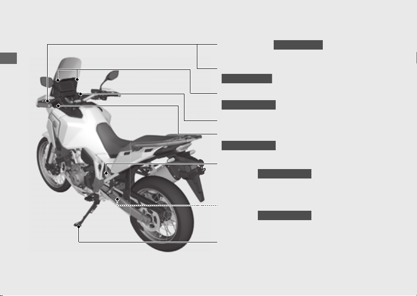
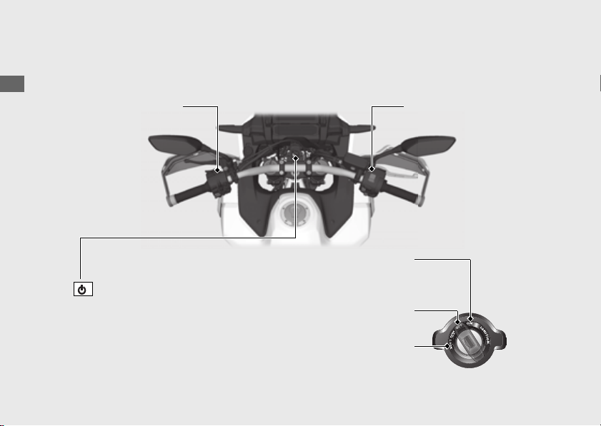
20
Parts Location
(Continued)
Operation Guide
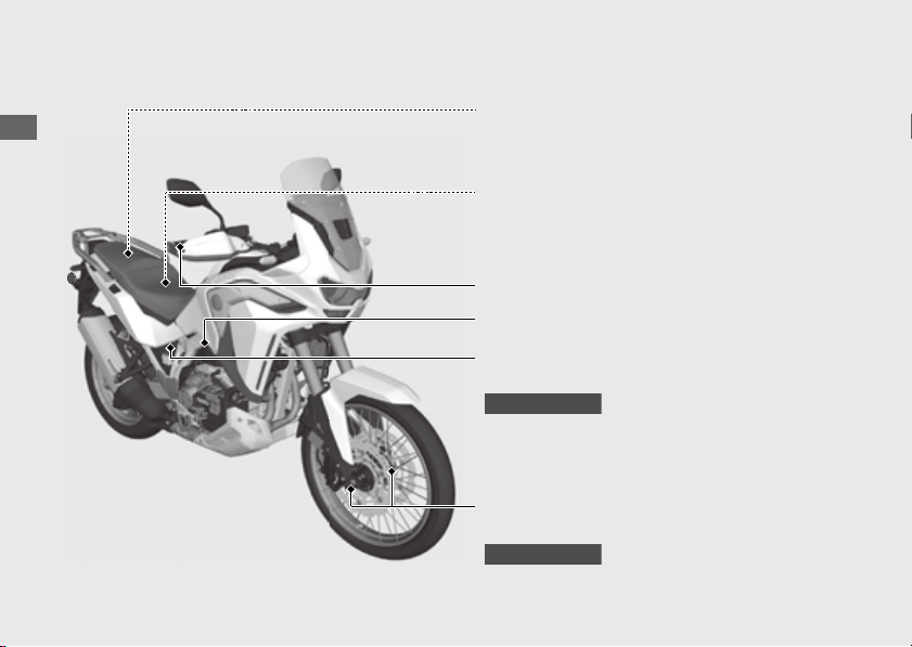
Clutch lever (P290)
CRF1100A/A4
Parking brake lever
(P283)
CRF1100D/D4
Accessory socket
(P237)
CRF1100A4/D4
Windscreen lock lever
(P305)
CRF1100A4/D4
USB socket (P238)
Rear suspension spring preload
adjuster
(P299)
CRF1100A/D
Rear suspension rebound damping
adjuster
(P302)
CRF1100A/D
Side stand (P285)
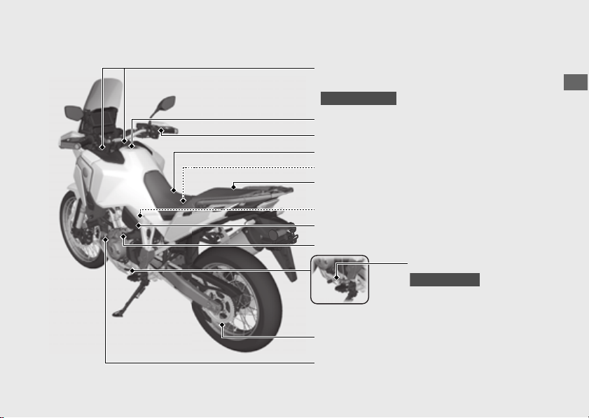
21
Operation Guide
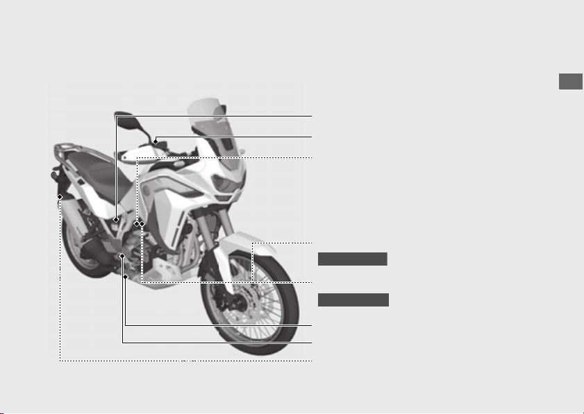
Front suspension spring preload/
rebound damping adjusters
(P295) (P296)
CRF1100A/D
Fuel fill cap (P236)
Tool kit/Tool box (P242) (P274)
Fuse box & ABS FSR fuse (P334)
Engine oil fill cap (P277)
Battery (P267)
Drive chain (P286)
Engine oil dipstick (P277)
Shift lever
(P222)
CRF1100A/A4
Front seat (P270)
Rear seat (P273)
Front brake lever (P294)
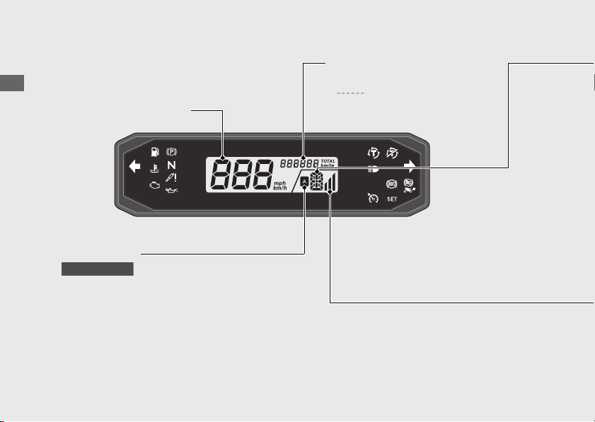
22
Operation Guide
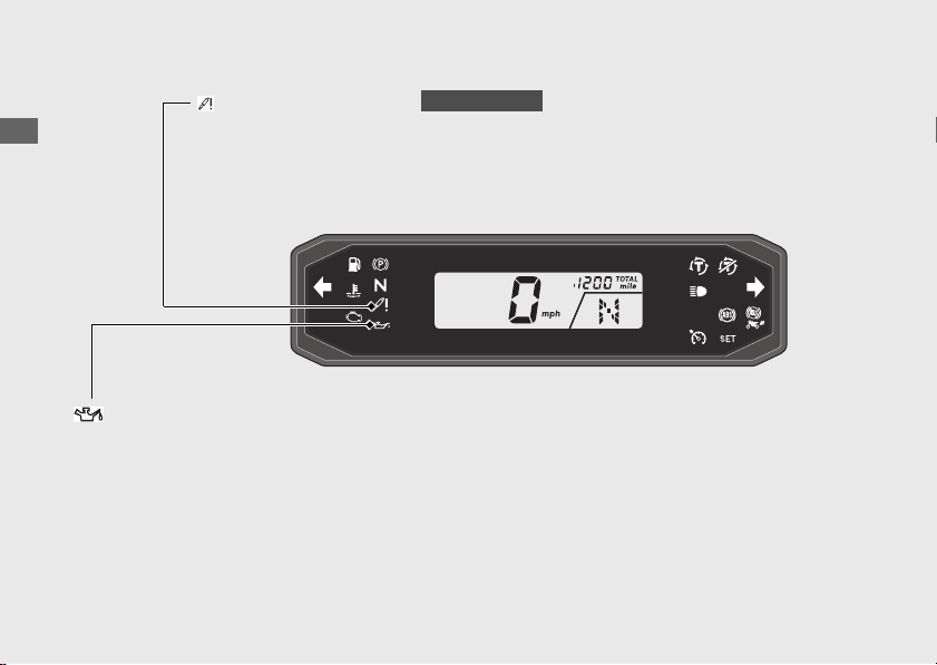
Instruments
Display Check
When the ignition switch is turned to the ON position, all the mode and digital segments
will show. If any part of these displays does not come on when it should, have your dealer
check for problems.
Speedometer
Odometer [TOTAL]
Total distance ridden. When
“ ” is displayed, have your
dealer check for problems.
AT indicator
Comes on when in AT MODE.
(P226)
CRF1100D/D4

23
Continued
Operation Guide
If the “-” indicator is blinking in the gear position window while riding: (P313)
The gear position is shown in the gear position indicator.
CRF1100A/A4
Gear position indicator
u “-” appears when the transmission is not shifted properly.
This is normal. To operate the system again, turn the ignition switch to the OFF position,
and then to the ON position again.
u The front wheel leaves the ground.
u You turn the wheel while the vehicle is upright on the stand.
The gear position is shown in the gear position indicator when the MT MODE is selected.
The indicator may flash if:
CRF1100D/D4
S mode level indicator (P226)
CRF1100D/D4
D is shown in the gear position indicator when the D mode is selected in the AT MODE.
S is shown in the gear position indicator when the S mode is selected in the AT MODE.
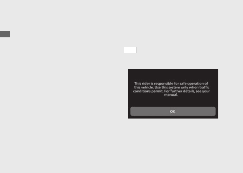
24
Instruments
(Continued)
Operation Guide
Multi-information display
Your vehicle is equipped with a multi-
information display that presents various
functions and settings.
The multi-information display is a touch
screen. You can operate by touching the
screen.
● Certain manual functions and settings are
disabled or inoperable while the vehicle is
in motion. You cannot select a greyed-out
menu until the vehicle is stopped.
When the ignition switch is turned ON, the
Notice message appears on the screen for a
few seconds.
Read the Notice message, and then press the
switch or touch [OK] on the screen.
After about 4 seconds, it will switch to the
home screen.
ENT
25
Operation Guide
Continued
#
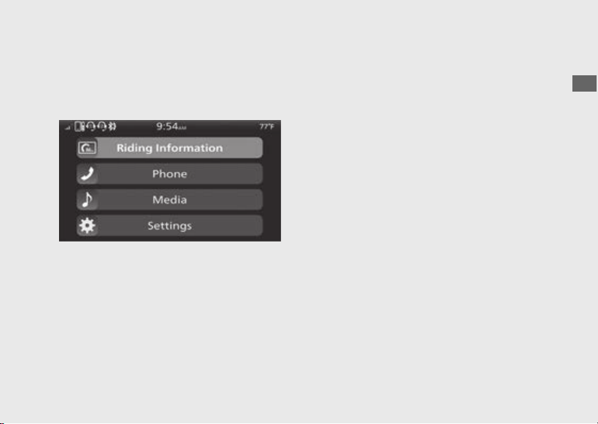
Home Screen
From this screen, you can go to various
functions and setup options.
To return to the Home screen:
(P36)
#
Riding Information
You can go back to the riding information.
Riding information has 3 displays, Gold image
display, Silver image display and Bronze
image display.
These displays are switched according to
riding mode.
Gold image display
(P26)
Silver image display (P30)
Bronze image display (P33)
To change the display setting on each riding
mode
(P79)
#
Phone
You can make calls using a connected
Bluetooth
®
audio devices.
#
Media
You can play music from Bluetooth
®
devices.
#
Settings
You can select various settings.
26
Instruments
(Continued)
Operation Guide
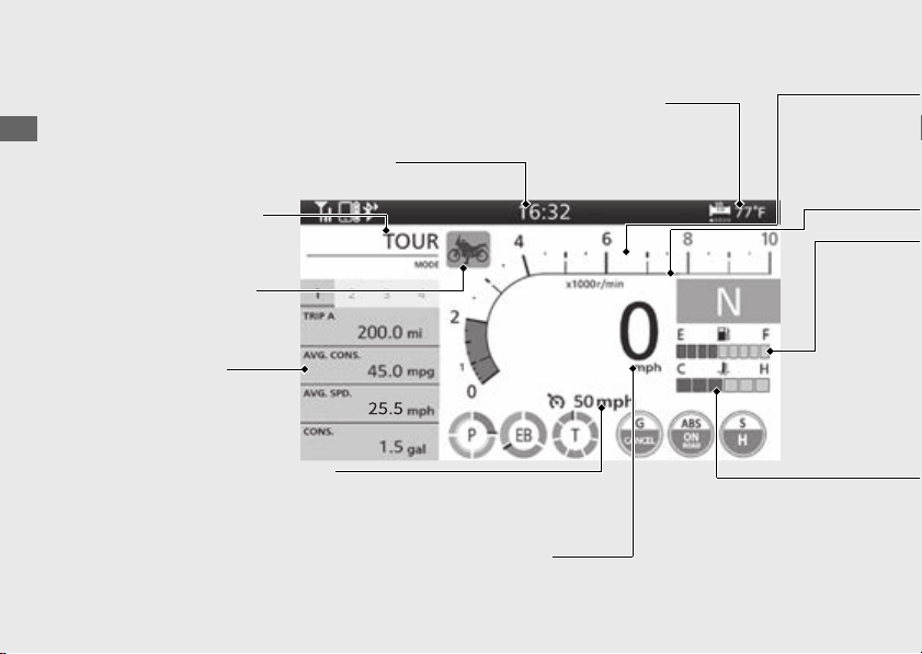
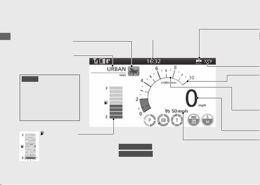
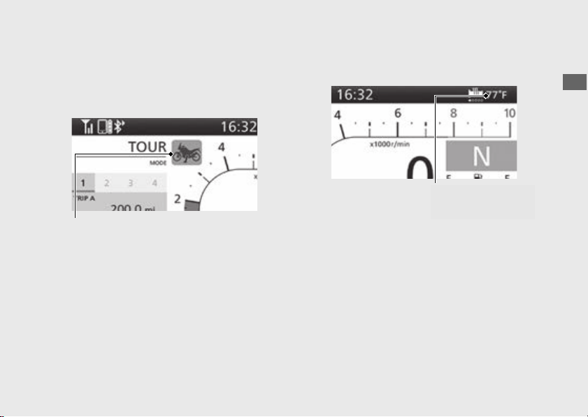
Gold image display
Riding mode display
(P139)
Side stand indicator
(P65)
Clock (12-hour or 24-hour display)
To set the clock:
(P88)
Cruise Control Set Speed
The speed set for cruise
control is displayed.
Cruise Control:
(P230)
Speedometer
Sub-information
indicator
(P39)
Air temperature gauge
(P65)
#
Riding Information
27
Continued
Operation Guide
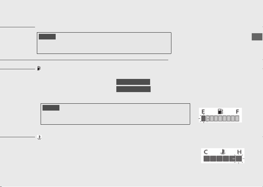
Tachometer
NOTICE
Do not operate the engine in the Tachometer red zone. Excessive engine
speed can adversely affect engine life.
Tachometer red zone
(excessive engine rpm range)
Coolant temperature gauge
When the coolant is over specified temperature, all segments turn
red and the H (6th) segment flashes and high coolant temperature
indicator lamps.
(P309)
If the coolant temperature gauge indicator flashes:
(P315)
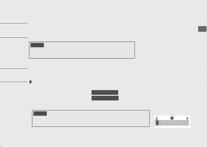
Fuel gauge
Remaining fuel when only E (1st) segment starts flashing:
Approximately 0.95 US gal (3.6 L)
Approximately 1.03 US gal (3.9 L)
If the fuel gauge indicator flashes:
(P314)
CRF1100A/D
CRF1100A4/D4
NOTICE
You should refuel when the reading approaches the E (1st) segment. Running out
of fuel can cause the engine to misfire, damaging the catalytic converter.
28
Instruments
(Continued)
Operation Guide
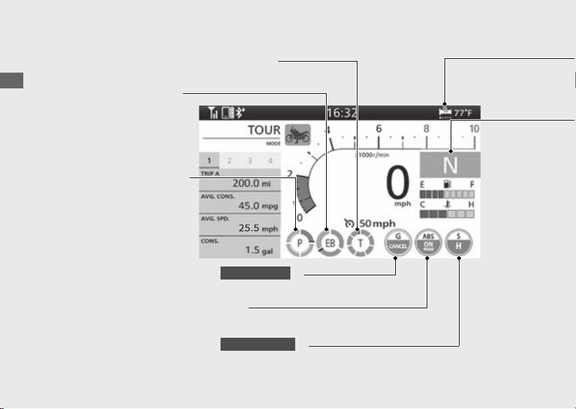
[P] [Power] level indicator
(P139)
When the indicator flashes,
have your dealer check for
problems.
[EB] [Engine Brake] level
indicator
(P139)
When the indicator flashes,
have your dealer check for
problems.
Torque Control level [T] indicator
(P131)
When the indicator flashes, have your dealer check for problems.
G switch [G] indicator (P124)
When the indicator flashes, have your dealer check for problems.
CRF1100D/D4
ABS mode [ABS] indicator (P139)
When the indicator flashes, have your dealer check for problems.
[S] [Overall] indicator
(P139)
When the indicator flashes, have your dealer check for problems.
CRF1100A4/D4

29
Continued
Operation Guide
If the “-” indicator is blinking in the gear position window while riding: (P313)
The gear position is shown in the gear position indicator.
CRF1100A/A4
Gear position indicator
u “-” appears when the transmission is not shifted properly.
This is normal. To operate the system again, turn the ignition switch to the OFF position,
and then to the ON position again.
u The front wheel leaves the ground.
u You turn the wheel while the vehicle is upright on the stand.
The gear position is shown in the gear position indicator.
The indicator may flash if:
CRF1100D/D4
D is shown in the gear position indicator when the D mode is selected in the AT MODE.
S is shown in the gear position indicator when the S mode is selected in the AT MODE.
S mode level indicator
(P226)
Handle grip heater status icon
The handle grip heater status icon will appear while the handle grip heater is on.
(P130)
If the handle grip heater status icon flashes:
(P315)
CRF1100A4/D4
30
Instruments
(Continued)
Operation Guide
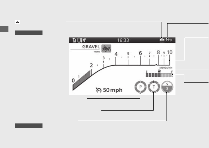
Silver image display
Riding mode display
(P139)
Clock (12-hour or 24-hour display)
To set the clock:
(P88)
Fuel gauge
Remaining fuel when only E (1st) segment starts flashing:
Approximately 0.95 US gal (3.6 L)
Approximately 1.03 US gal (3.9 L)
If the fuel gauge indicator flashes:
(P314)
CRF1100A/D
CRF1100A4/D4
NOTICE
You should refuel when the
reading approaches the E (1st)
segment. Running out of fuel
can cause the engine to misfire,
damaging the catalytic
converter.
Side stand indicator
(P65)

31
Continued
Operation Guide
Tachometer
NOTICE
Do not operate the engine in the Tachometer red zone. Excessive engine
speed can adversely affect engine life.
Tachometer red zone
(excessive engine rpm range)
Air temperature gauge
(P65)
Speedometer
Cruise Control Set Speed
The speed set for cruise control is displayed.
Cruise Control: (P230)
Handle grip heater status icon
The handle grip heater status icon will appear while the handle grip heater is on.
(P130)
If the handle grip heater status icon flashes: (P315)
CRF1100A4/D4
32
Instruments
(Continued)
Operation Guide
[S] [Overall] indicator
(P139)
When the indicator flashes, have your dealer
check for problems.
CRF1100A4/D4
Sub-information
indicator
(P39)
ABS mode [ABS] indicator
(P139)
When the indicator flashes, have your
dealer check for problems.
Torque Control level [T] indicator
(P131)
When the indicator flashes, have your dealer check for problems.
[EB] [Engine Brake] level
indicator (P139)
When the indicator flashes,
have your dealer check for
problems.
[P] [Power] level
indicator
(P139)
When the indicator flashes,
have your dealer check for
problems.

34
Instruments
(Continued)
Operation Guide
[P] [Power] level indicator
(P139)
When the indicator flashes, have your dealer check for problems.
Torque Control level [T] indicator
(P131)
When the indicator flashes, have your dealer check for problems.
Handle grip heater
status icon
The handle grip heater
status icon will appear while
the handle grip heater is on.
(P130)
If the handle grip heater
status icon flashes:
(P315)
CRF1100A4/D4
[S] [Overall] indicator
(P139)
When the indicator flashes, have your dealer check for problems.
CRF1100A4/D4
35
Continued
Operation Guide
Tachometer
NOTICE
Do not operate the engine in the Tachometer red zone. Excessive engine
speed can adversely affect engine life.
Tachometer red zone
(excessive engine rpm range)
Air temperature gauge
(P65)
Fuel gauge
Remaining fuel when only E (1st) segment starts flashing:
Approximately 0.95 US gal (3.6 L)
Approximately 1.03 US gal (3.9 L)
If the fuel gauge indicator flashes:
(P314)
CRF1100A/D
CRF1100A4/D4
NOTICE
You should refuel when the reading approaches the E (1st) segment. Running out
of fuel can cause the engine to misfire, damaging the catalytic converter.
36
Instruments
(Continued)
Operation Guide
#
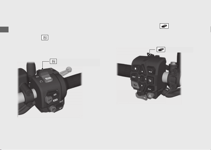
Basic Operations
You can operate and set the various functions of
your vehicle using the switches on the left
handlebar and function sel switch on the
right handlebar or touch screen.
However, you cannot operate some functions
while the vehicle is in motion.
To Return to the Home Screen
Pull backward and hold the page switch
on the left handlebar or touch the clock area
of the multi-information display with your
vehicle stopped.
Function sel switch
Page switch
37
Operation Guide
Continued
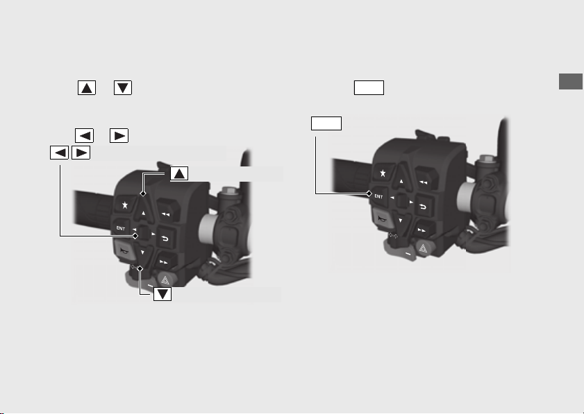
To Select a Desired Setting Menu
To operate with the left handlebar:
Press or to select the available
choices.
To operate with the left handlebar:
Push or to select the available choices.
To operate with the touch screen:
Touch the menu to be selected on the touch
screen.
To Set Your Selection
To operate with the left handlebar:
Press the switch on the left handlebar to
set your selection.
To operate with the touch screen:
Touch the menu to be selected on the touch
screen.
Sel left/right switch
Sel down switch
Sel up switch
ENT
switch
ENT
38
Instruments
(Continued)
Operation Guide
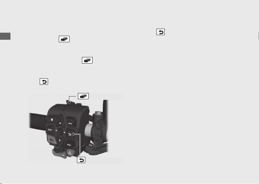
To Exit the Setting Menu
To return to the riding information:
Pull backward the page switch on the left
handlebar.
To return to the Home screen:
Pull backward and hold the page switch
on the left handlebar.
To return the previous screen:
Press the back switch on the left
handlebar.
To operate with the touch screen:
Touch the to be selected on the touch
screen.
Also, the setting mode ends when your
vehicle speed reaches approximately 4 mph (6
km/h).
Page switch
Back switch
39
Operation Guide
Continued
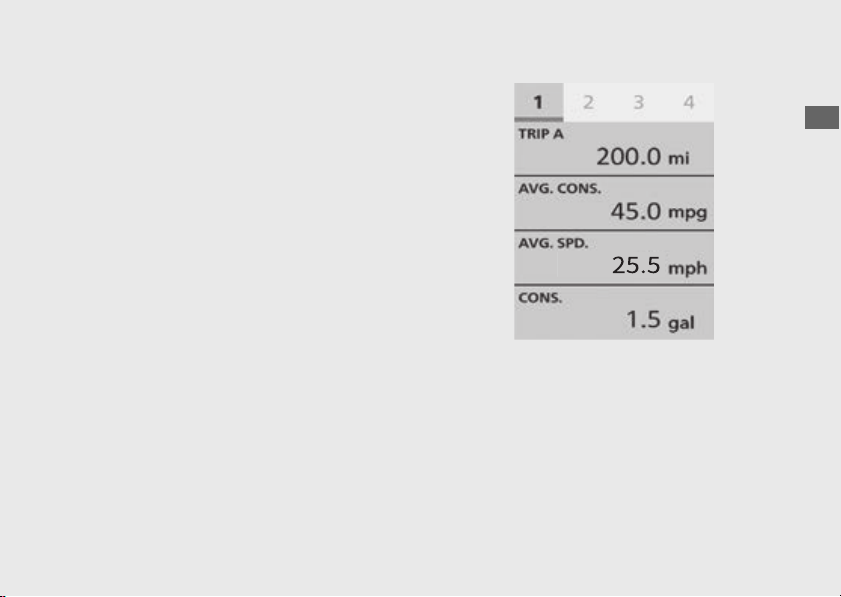
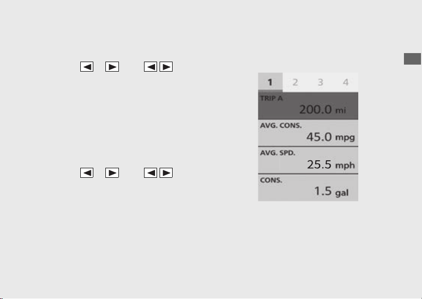
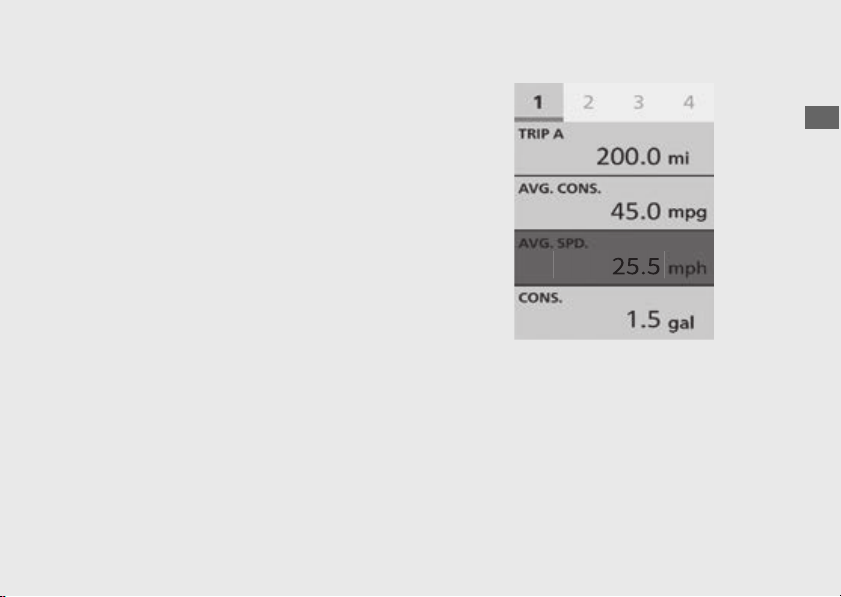
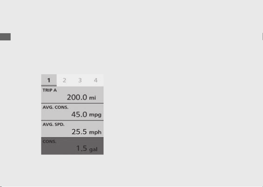
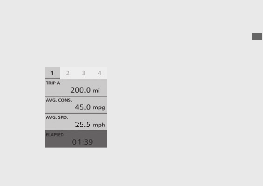
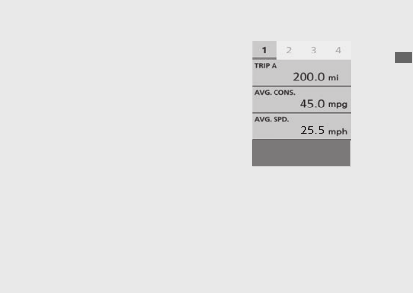
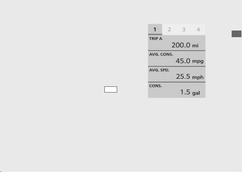
#
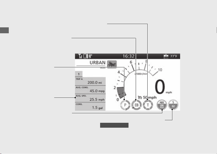
Page 1:
Page 1 shows the following items: Tripmeter A
[TRIP A] and three items related to Tripmeter
A [TRIP A] and Tripmeter B [TRIP B].
(P84)
● Tripmeter A average fuel mileage [AVG.
CONS.] display
(P44)
● Tripmeter A average speed [AVG. SPD.]
display (P50)
● Tripmeter A current fuel mileage [CONS.]
display (P46)
● Tripmeter A elapsed [ELAPSED] display
(P47)
● Blank (P59)

40
Instruments
(Continued)
Operation Guide
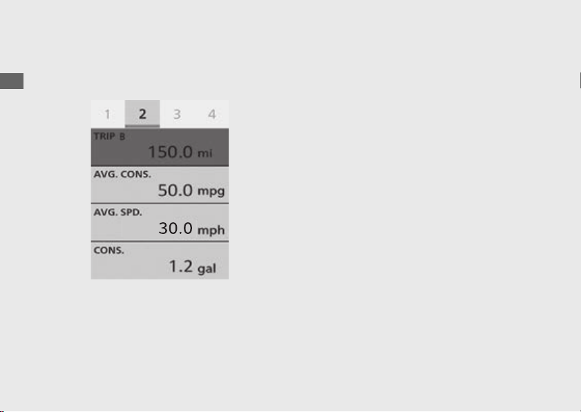
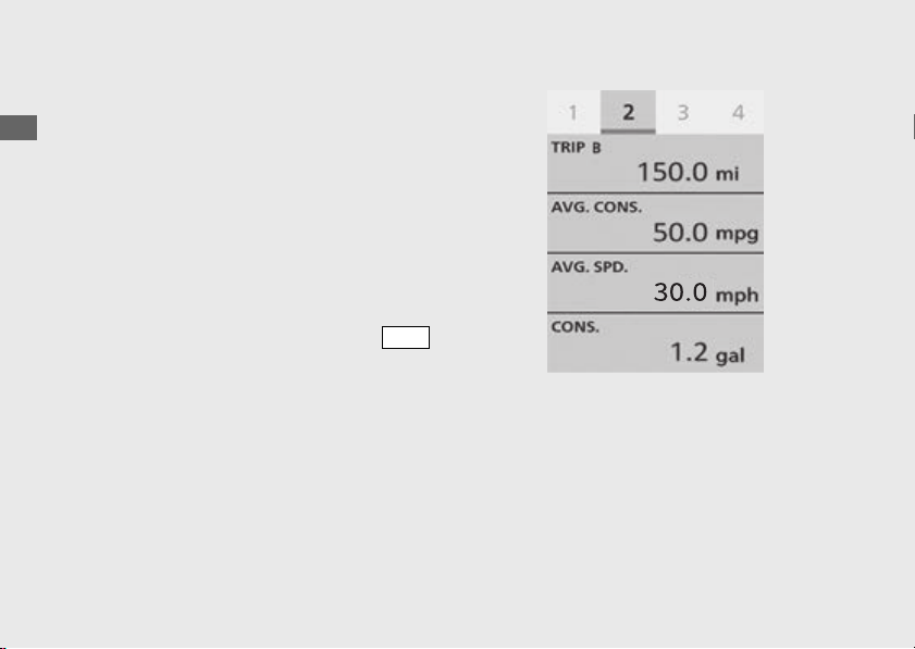
#
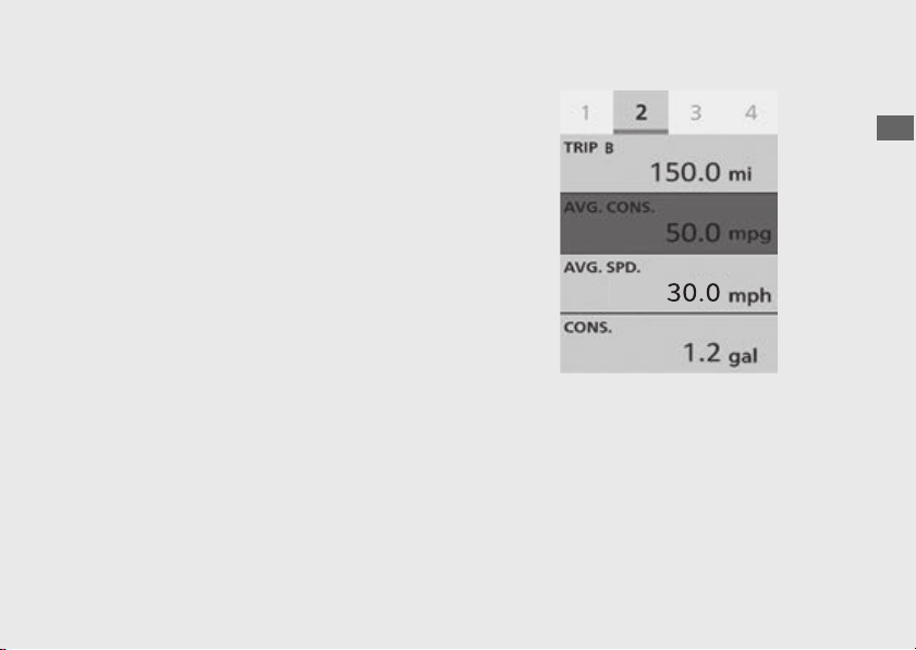
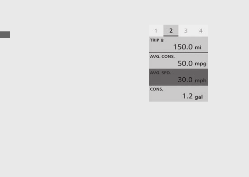
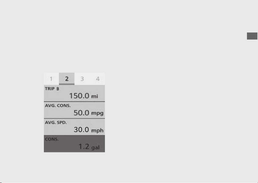
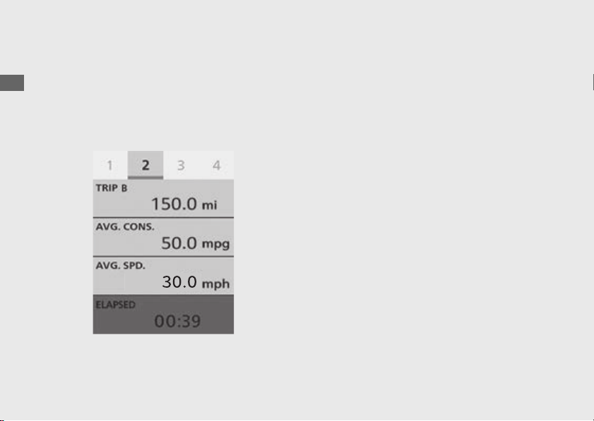
Page 2:
Page 2 shows the following items: Tripmeter B
[TRIP B] and three items related to Tripmeter B
[TRIP B].
(P84)
● Tripmeter B average fuel mileage [AVG.
CONS.] display
(P49)
● Tripmeter B average speed [AVG. SPD.]
display (P50)
● Tripmeter B current fuel mileage [CONS.]
display (P51)
● Tripmeter B elapsed [ELAPSED] display
(P52)
● Blank (P59)
41
Operation Guide
Continued
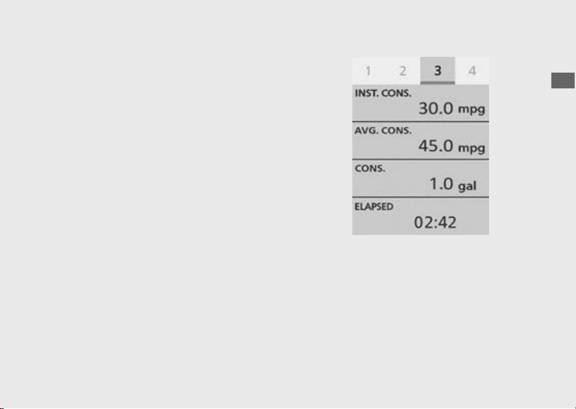
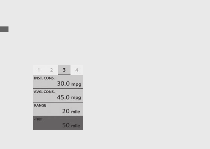
#
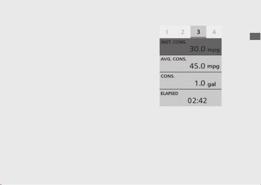
Page 3:
Page 3 shows four items selected from the
following items.
(P84)
● Current fuel mileage [INST. CONS.] display
(P53)
● Available driving distance [RANGE] display
(P54)
● Battery voltage [VOLTAGE] display (P55)
● Date [DATE] display (P55)
● Average fuel mileage [AVG. CONS.] display
(P56)
● Fuel consumption [CONS.] display (P57)
● Elapsed time [ELAPSED] display (P57)
● Subtraction trip [-TRIP] display (P58)
● Blank (P59)
42
Instruments
(Continued)
Operation Guide
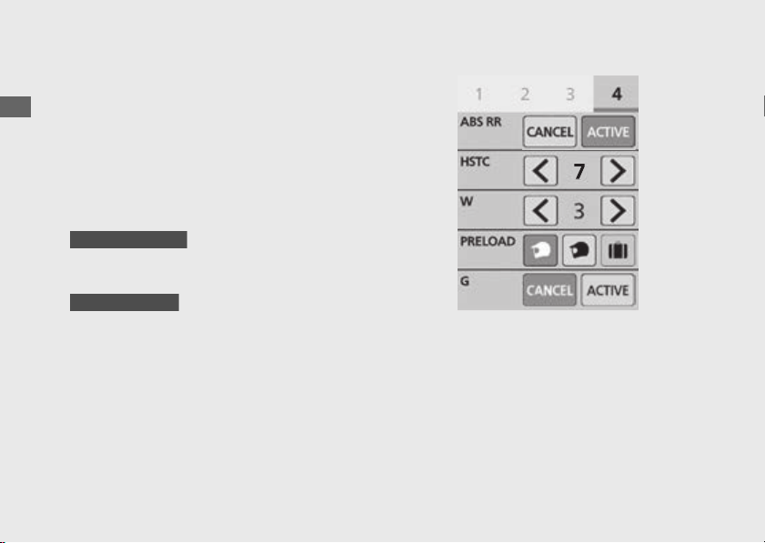
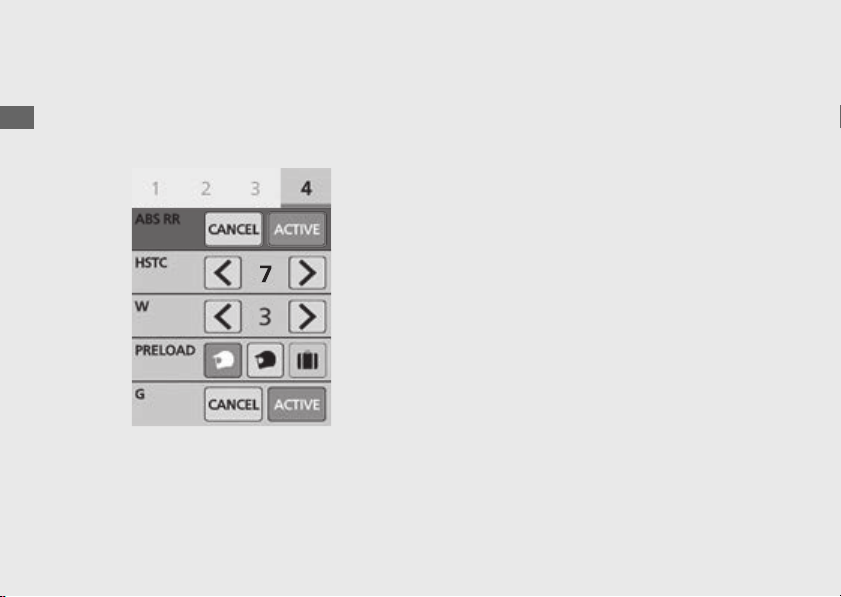
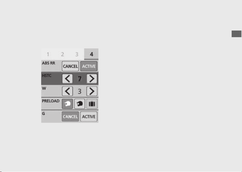
#
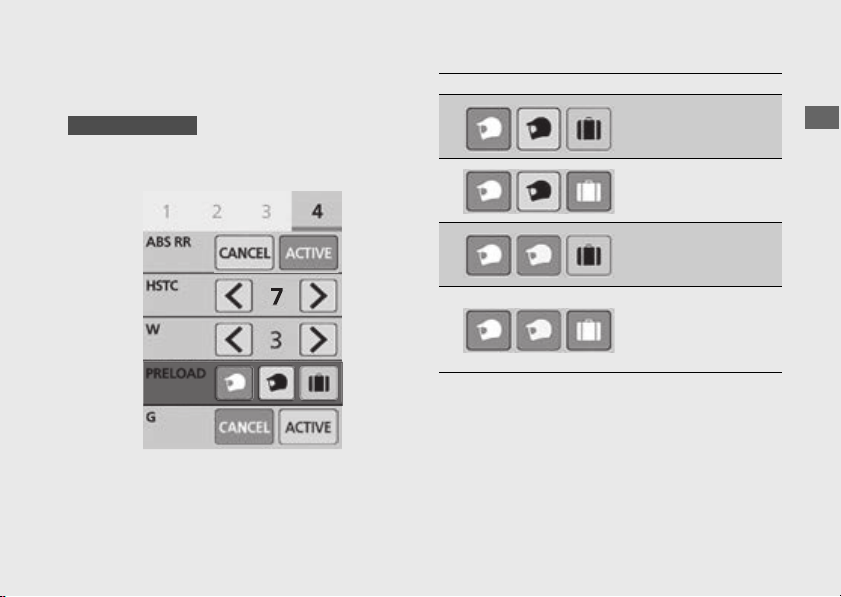
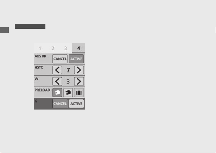
Page 4:
Page 4 shows the setting values of the
following items.
● ABS function on the rear wheel [ABS RR]
display
(P60)
● Honda Selectable Torque Control level
[HSTC] display (P61)
● Wheelie Control level [W] display (P62)
●
Rear suspension preload level [PRELOAD]
display (P63)
●
G switch [G] display (P64)
CRF1100A4/D4
CRF1100D/D4
43
Operation Guide
Continued
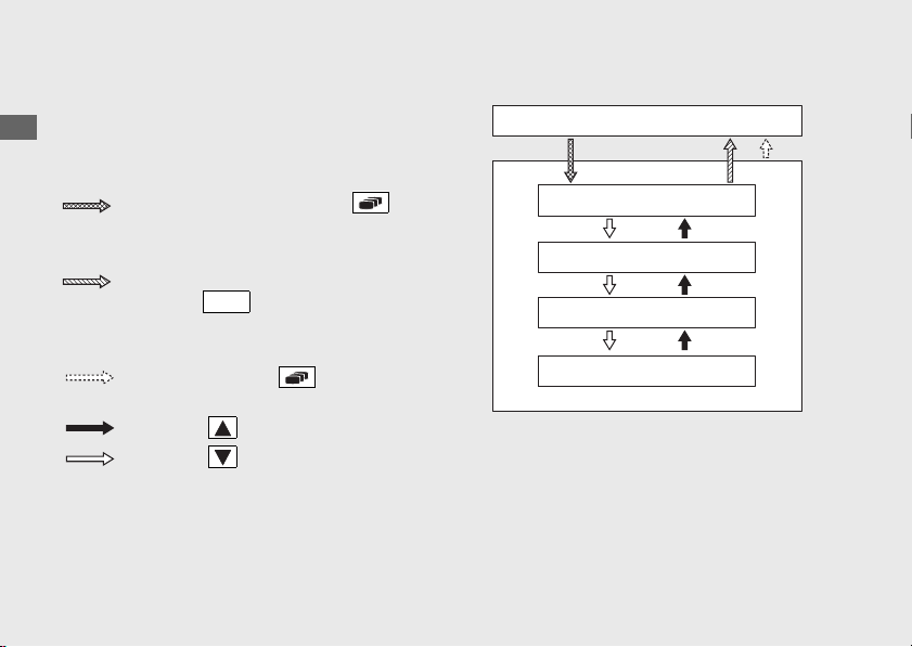
#
To Switch the Page of Display
!a Select the gold image display. (P79)
!b Push the or of the sel left/
right switch until the desired page is
displayed.
You can also perform the above settings by
using the touch screen.
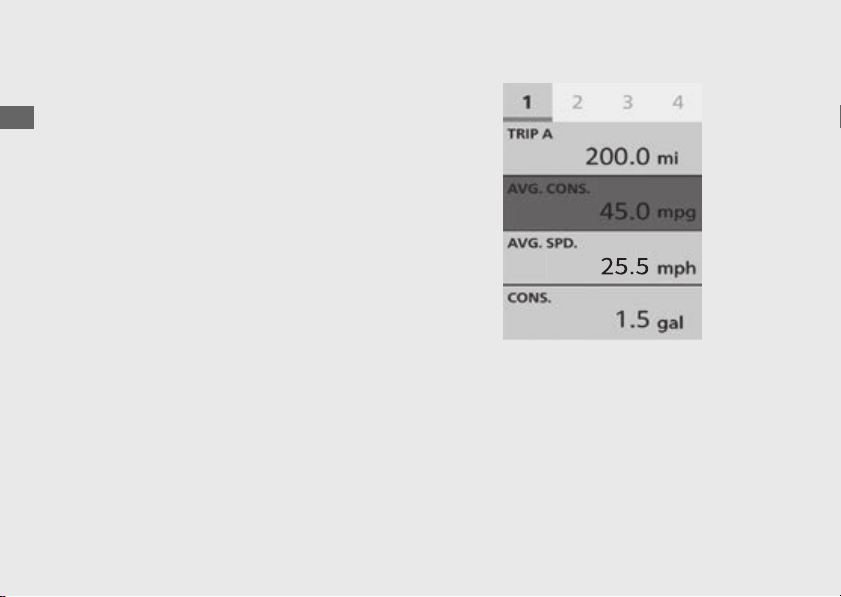
#
To Switch the Page 1 or Fuel Gauge
!a Select the silver image display. (P79)
!b Push the or of the sel left/
right switch to switch the page or fuel gauge.
#
Tripmeter A [TRIP A]
Distance ridden since the tripmeter A was
reset.
When “---.-” flashes, have your dealer check
for problems.
To reset the tripmeter A [TRIP A]:
(P67)
44
Instruments
(Continued)
Operation Guide
#
Tripmeter A Average Fuel Mileage
[AVG. CONS.]
Displays the average fuel mileage since the
tripmeter A was reset.
The average fuel mileage will be calculated
based on the value displayed on the selected
tripmeter A.
Display range: 0.0 to 299.9 mpg (km/l, l/100
km or mile/L)
● Initial display: “---.-” is displayed.
● More than 299.9 mpg (km/l, or mile/L):
“299.9” is displayed.
● More than 299.9 l/100 km: “---.-” is
displayed.
● When the tripmeter A is reset: “---.-” is
displayed.
When “---.-” flashes, have your dealer check
for problems.
To reset the tripmeter A average fuel
mileage [AVG. CONS.]:
(P67)
45
Operation Guide
Continued
#
Tripmeter A Average Speed [AVG. SPD.]
Displays the average speed since the
tripmeter A was reset.
The average speed will be calculated based
on the value displayed on the selected
tripmeter A.
● When the tripmeter A average speed is
reset: “299.0” is displayed
Display range: 0.0 to 186.0 mph or 0.0 to
299.0 km/h
To reset the tripmeter A average speed
[AVG. SPD.]:
(P67)
46
Instruments
(Continued)
Operation Guide
#
Tripmeter A Fuel Consumption [CONS.]
Displays the tripmeter A fuel consumption
since the tripmeter A was reset.
Display range: 0.0 to 300.0 gal (L)
● Above 300.0 gal (L): “300.0” is displayed.
● When the tripmeter A fuel consumption is
reset: “299.9” is displayed.
To reset the tripmeter A fuel
consumption [CONS.]:
(P67)
47
Operation Guide
Continued
#
Tripmeter A Elapsed [ELAPSED]
Displays the tripmeter A elapsed since the
tripmeter A was reset.
Display range: 00:00 to 99:59 (hours:minutes)
● The display locks at “99:59” when the read-
out exceeds 99:59.
When “00:00” flashes, have your dealer check
for problems.
To reset the tripmeter A elapsed
[ELAPSED]:
(P67)
49
Operation Guide
Continued
#
Tripmeter B Average Fuel Mileage
[AVG. CONS.]
Displays the average fuel mileage since the
tripmeter B was reset.
The average fuel mileage will be calculated
based on the value displayed on the selected
tripmeter B.
Display range: 0.0 to 299.9 mpg (km/l, l/100
km or mile/L)
● Initial display: “---.-” is displayed.
● More than 299.9 mpg (km/l or mile/L):
“299.9” is displayed.
● More than 299.9 l/100 km: “---.-” is
displayed.
● When the tripmeter B is reset: “---.-” is
displayed.
When “---.-” flashes, have your dealer check
for problems.
To reset the tripmeter B average fuel
mileage [AVG. CONS.]:
(P68)
50
Instruments
(Continued)
Operation Guide
#
Tripmeter B Average Speed [AVG. SPD.]
Displays the average speed since the
tripmeter B was reset.
The average speed will be calculated based
on the value displayed on the selected
tripmeter B.
● When the tripmeter A average speed is
reset: “299.0” is displayed
Display range: 0.0 to 186.0 mph or 0.0 to
299.0 km/h
To reset the tripmeter B average speed
[AVG. SPD.]:
(P68)
51
Operation Guide
Continued
#
Tripmeter B Fuel Consumption [CONS.]
Displays the tripmeter B fuel consumption
since the tripmeter B was reset.
Display range: 0.0 to 300.0 gal (L)
● Above 300.0 gal (L): “300.0” is displayed.
● When the tripmeter B fuel consumption is
reset: “299.9” is displayed.
To reset the tripmeter B fuel
consumption [CONS.]:
(P68)
52
Instruments
(Continued)
Operation Guide
#
Tripmeter B Elapsed [ELAPSED]
Displays the tripmeter B elapsed since the
tripmeter B was reset.
Display range: 00:00 to 99:59 (hours:minutes)
● The display locks at “99:59” when the read-
out exceeds 99:59.
When “00:00” flashes, have your dealer check
for problems.
To reset the tripmeter B elapsed
[ELAPSED]:
(P68)
53
Operation Guide
Continued
#
Current Fuel Mileage [INST. CONS.]
Displays the current instant fuel mileage
Display range: 0.0 to 299.9 mpg (km/l, l/100
km or mile/L)
● When your speed is less than 1 mph (3 km/
h): “---.-” is displayed.
● Above 299.9 mpg (km/l or mile/L):“299.9” is
displayed.
● Above 299.9 l/100 km: “---.-” is displayed.
When “---.-” flashes, have your dealer check
for problems.
54
Instruments
(Continued)
Operation Guide
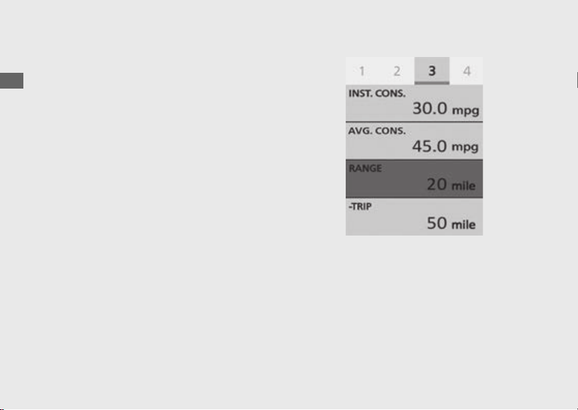
#
Available Driving Distance [RANGE]
Displays the estimated distance you can travel
on the remaining fuel.
Display range: 999 to 0 mile (999 to 0 km)
● Above 999 mile (km): “999” is displayed.
● Initial display: “0” is displayed.
● When the available driving distance is
below 3 mile (5 km) or the amount of
remaining fuel is below 0.2 gal (1.0 L), “---”
is displayed.
The indicated available driving distance is
calculated based on driving conditions, and
the indicated figure may not always be the
actual allowable distance.

56
Instruments
(Continued)
Operation Guide
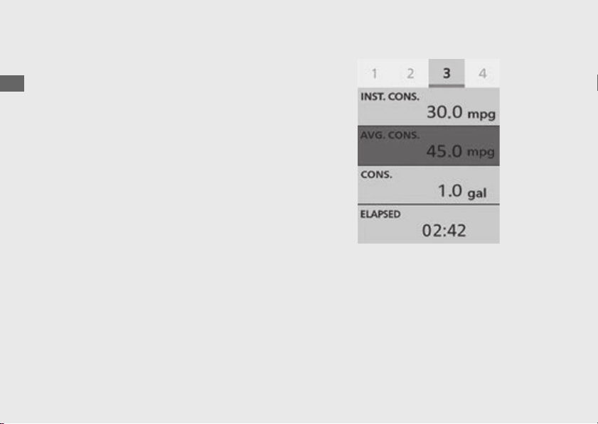
#
Average Fuel Mileage [AVG. CONS.]
Displays the average fuel mileage since the
average fuel mileage was reset.
Display range: 0.0 to 299.9 mpg (km/l, l/100
km or mile/L)
● Initial display: “---.-” is displayed.
● More than 299.9 mpg (km/l or mile/L):
“299.9” is displayed.
● More than 299.9 l/100 km: “---.-” is
displayed.
● When the average fuel mileage [AVG.
CONS.] is reset: “---.-” is displayed.
When “---.-” flashes, have your dealer check
for problems.
To reset the average fuel mileage [AVG.
CONS.]:
(P69)
57
Operation Guide
Continued
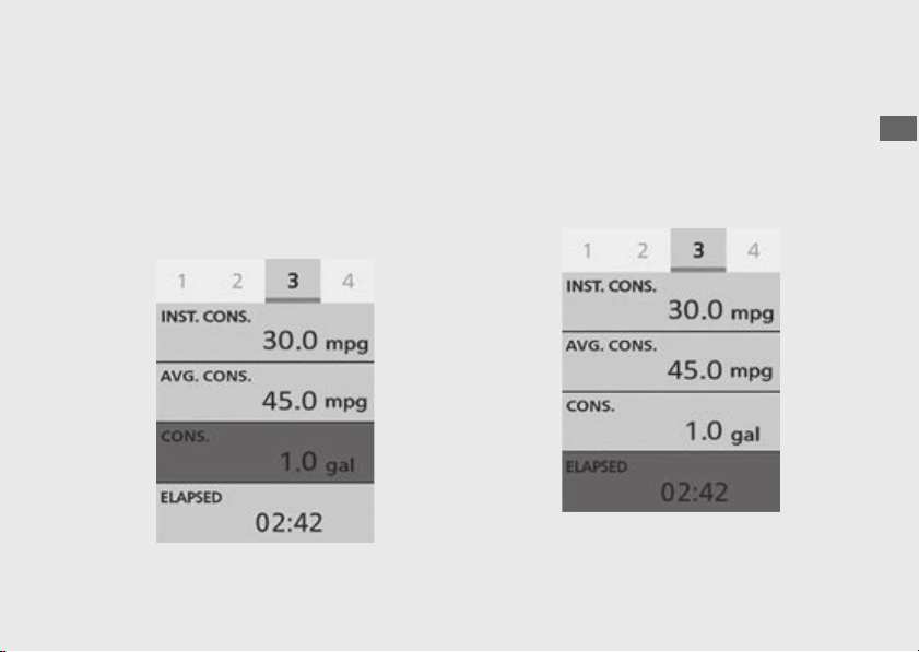
#
Fuel Consumption [CONS.]
Displays the fuel consumption.
Display range: 0.0 to 300.0 gal or 0.0 to 300.0
L
● Above 300.0 gal (L): “300.0” is displayed.
● When the engine is starts: “---.-” is
displayed.
#
Elapsed Time [ELAPSED]
Displays operating time since the engine was
started.
Display range: 00:00 to 99:59 (hours:minutes)
● The display locks at “99:59” when the read-
out exceeds 99:59.
When “00:00” flashes, have your dealer check
for problems.
58
Instruments
(Continued)
Operation Guide
#
Subtraction Trip [-TRIP]
Distance travelled is subtracted from a preset
figure, since the subtraction trip was set up.
Display range: 999 to -1,000 mile or 1,607 to -
1,609 km
The display locks at “-1000” mile (“-1609” km)
when the read-out exceeds -1000 mile (-1609
km).
To set the subtraction trip:
(P77)
Default: 000
59
Operation Guide
Continued
#
Blank
Display is blank.

63
Operation Guide
Continued
#
Rear Suspension Preload Mode
[PRELOAD]
Displays the selected status of the rear
suspension preload mode [PRELOAD].
Default: Rider only
To select the rear suspension preload
mode [PRELOAD]:
(P300)
CRF1100A4/D4
Status icon Riding condition
Rider only
(Minimum preload)
Rider and luggage
Rider and
passenger
Rider, passenger
and luggage
(Maximum
preload)
64
Instruments
(Continued)
Operation Guide
#
G Switch [G]
Displays the selected status of the G switch
[G].
Available settings: [ACTIVE]/[CANCEL]
Default:
● [TOUR MODE]: [CANCEL]
● [URBAN MODE]: [CANCEL]
● [GRAVEL MODE]: [CANCEL]
● [OFF ROAD MODE]: [ACTIVE]
● [USER 1 MODE]: [CANCEL]
● [USER 2 MODE]: [CANCEL]
To select the G switch [G]:
(P124)
CRF1100D/D4
65
Operation Guide
Continued
#
Side Stand Indicator
The side stand indicator comes on when the
side stand is put down. It goes off when the
side stand is raised.
#
Air temperature gauge
Displays the ambient temperature.
Side stand indicator
Air temperature
gauge
66
Instruments
(Continued)
Operation Guide
Display range: 14 ºF (-10 ºC) to 122 ºF (50 ºC)
● Below 13ºF (-11ºC): “---” is displayed
● Above 122ºF (50ºC): 122ºF (50ºC) flashes
Road heat and exhaust from another vehicle
can affect the temperature reading when your
vehicle speed is less than 19 mph (30 km/h). It
may take several minutes for the display to be
updated after the temperature reading has
stabilized.
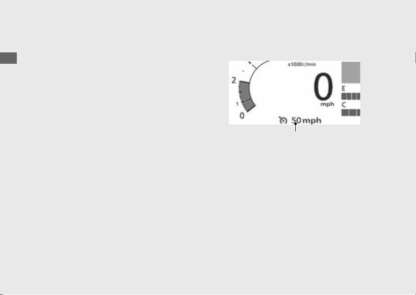
#
Cruise Control Set Speed
The speed set for cruise control is displayed.
To set the cruise control set speed:
(P232)
Cruise control set speed
67
Operation Guide
Continued
#
To Reset the Tripmeter A [TRIP A],
Tripmeter A Average Fuel Mileage
[AVG. CONS.], Tripmeter A Average
Speed [AVG. SPD.], Tripmeter A Fuel
Consumption [CONS.] and Tripmeter A
Elapsed [ELAPSED]
To reset the tripmeter A [TRIP A], tripmeter A
average fuel mileage [AVG. CONS.], tripmeter
A average speed [AVG. SPD.], tripmeter A fuel
consumption [CONS.] and tripmeter A
elapsed [ELAPSED], press and hold the
switch while page 1 is displayed or touch and
hold the page 1 area.
ENT
68
Instruments
(Continued)
Operation Guide
#
To Reset the Tripmeter B [TRIP B],
Tripmeter B Average Fuel Mileage
[AVG. CONS.], Tripmeter B Average
Speed [AVG. SPD.], Tripmeter B Fuel
Consumption [CONS.] and Tripmeter B
Elapsed [ELAPSED]
To reset the tripmeter B [TRIP B], tripmeter B
average fuel mileage [AVG. CONS.], tripmeter
B average speed [AVG. SPD.], tripmeter B fuel
consumption [CONS.] and tripmeter B
elapsed [ELAPSED], press and hold the
switch while page 2 is displayed or touch and
hold the page 2 area.
ENT

69
Operation Guide
Continued
#
To Reset the Average Fuel Mileage
[AVG. CONS.]
To reset the average fuel mileage [AVG.
CONS.], press and hold the switch while
page 3 is displayed or touch and hold the
page 3 area.
ENT
70
Instruments
(Continued)
Operation Guide
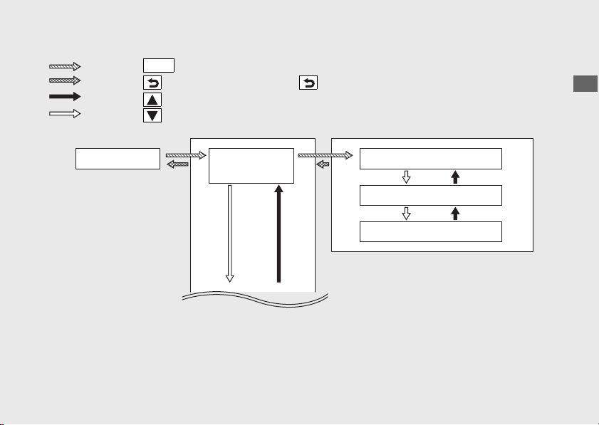
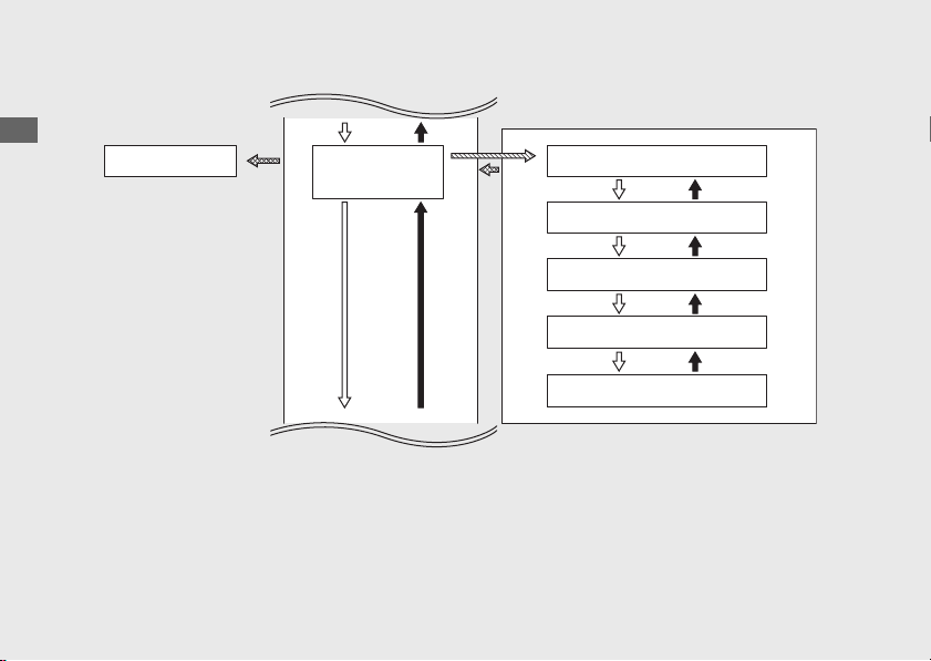
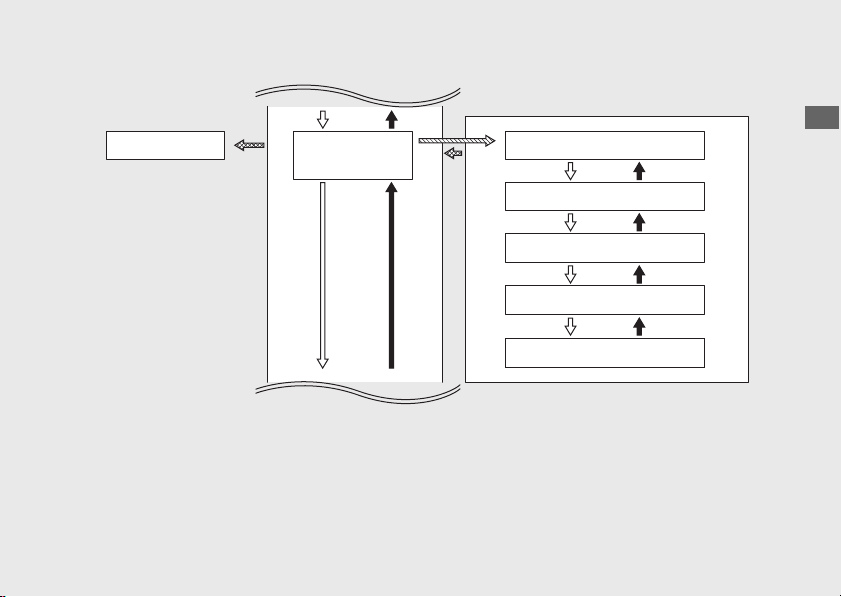
Setting mode
#
To Shift to the Menu of the Multi-
Information Display
Pull backward and hold the
page switch or touch the clock area
of the multi-information display.
Press the sel up switch.
Press the sel down switch.
Select [Riding Information], and then
press the switch or touch the
[Riding Information] of the multi-
information display.
ENT
Pull backward the page switch.
Riding Information
Media
(P155)
Phone (P179)
Settings
Home screen
Riding information
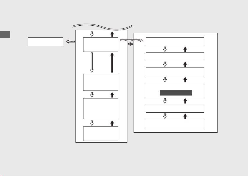
75
Operation Guide
Continued
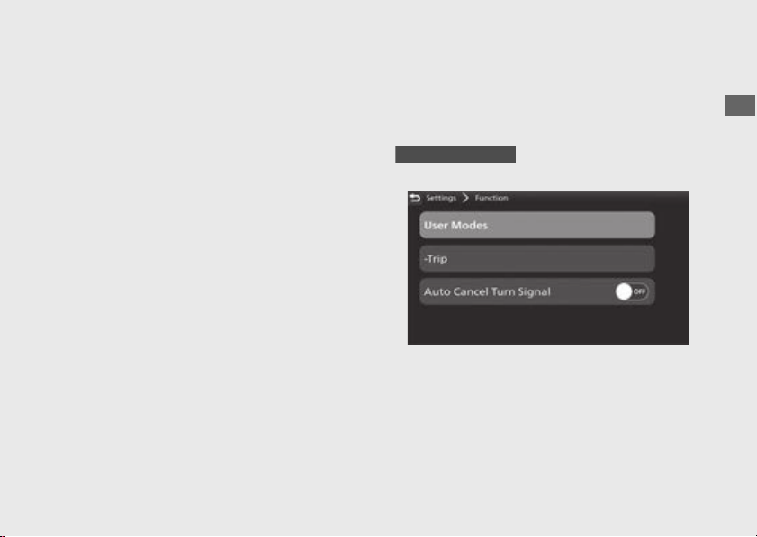
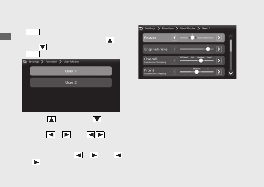
#
Function
Following items can be changed sequentially.
● User Modes (this page)
● -Trip
(P77)
● Auto Cancel Turn Signal (P78)
User Modes
You can change the [Power], [Engine Brake],
[Overall]
*1
, [Front]
*1
, [Rear]
*1
, [ABS], [Preload]
*1
values in [USER 1 MODE] and [USER 2 MODE].
*1: CRF1100A4/D4
76
Instruments
(Continued)
Operation Guide
!a Select [User Modes], and then press the
switch.
!b Select [User 1] or [User 2] using the sel
up or sel down switch, and then press the
switch.
!c Press the sel up switch or sel down
switch to select a setting menu.
!d Push the or of the sel left/
right switch until the desired value is
displayed.
u Push and hold the or of the
sel left/right switch to advance the
figure fast.
!e Return to the riding information, previous
screen or Home screen.
(P38)
You can also perform the above settings by
using the touch screen.
Available settings:
(P143)
Default: (P141)
ENT
ENT
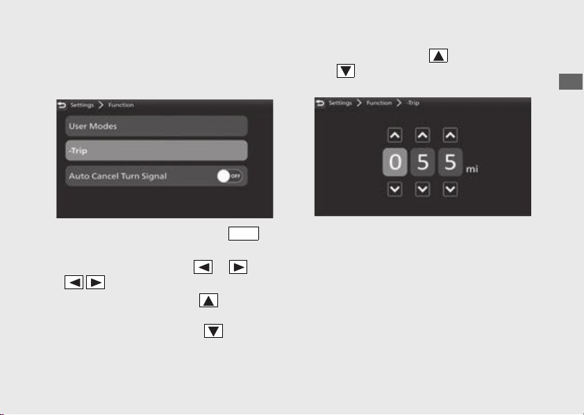
77
Operation Guide
Continued
-Trip
You can also adjust value of the subtraction
trip [-TRIP].
!a Select [-Trip], and then press the
switch.
!b Select the digits using the or of the
sel left/right switch.
!c To increase value: Press the sel up switch,
until the desired value is displayed.
To decrease value: Press the sel down
switch, until the desired value is displayed.
u Press and hold the sel up switch or sel
down switch to advance the figure
fast.
!d Return to the riding information, previous
screen or Home screen.
(P38)
You can also perform the above settings by
using the touch screen.
Setting range: 000 to 999
Default: 000
ENT
78
Instruments
(Continued)
Operation Guide
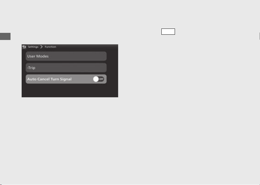
Auto Cancel Turn Signal
You can enable/disable turn signal automatic
cancellation.
!a Select [Auto Cancel Turn Signal], and then
press the switch to [ON] (enable) or
[OFF] (disable) the function.
!b Return to the riding information, previous
screen or Home screen.
(P38)
You can also perform the above settings by
using the touch screen.
Available settings: [ON]/[OFF]
Default: [ON]
ENT
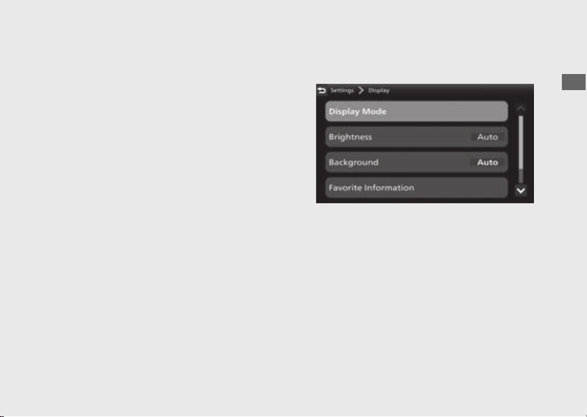
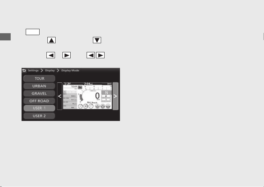
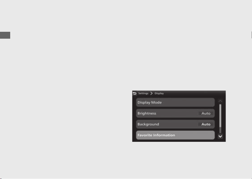
80
Instruments
(Continued)
Operation Guide
!a Select [Display Mode], and then press the
switch.
!b Press the sel up switch or sel down
switch to select a setting menu.
!c Push the or of the sel left/
right switch to select your desired display.
!d Return to the riding information, previous
screen or Home screen.
(P38)
You can also perform the above settings by
using the touch screen.
Available settings: Gold image/Silver
image/Bronze image
Default:
● [TOUR MODE]: Gold image
● [URBAN MODE]: Silver image
● [GRAVEL MODE]: Silver image
● [OFF ROAD MODE]: Bronze image
● [USER 1 MODE]: Silver image
● [USER 2 MODE]: Bronze image
ENT
81
Operation Guide
Continued
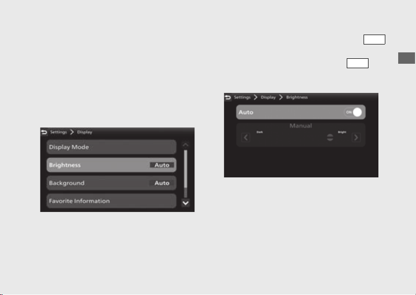
Brightness
You can select the backlight brightness.
The display can become dark when the
display is very hot. If it does not restore the
original brightness, contact your dealer.
Automatic Brightness Control:
(P344)
!a Select [Brightness], and then press the
switch.
!b Select [Auto], and then press the
switch to [ON] (auto) or [OFF] (manual) the
function.
ENT
ENT
82
Instruments
(Continued)
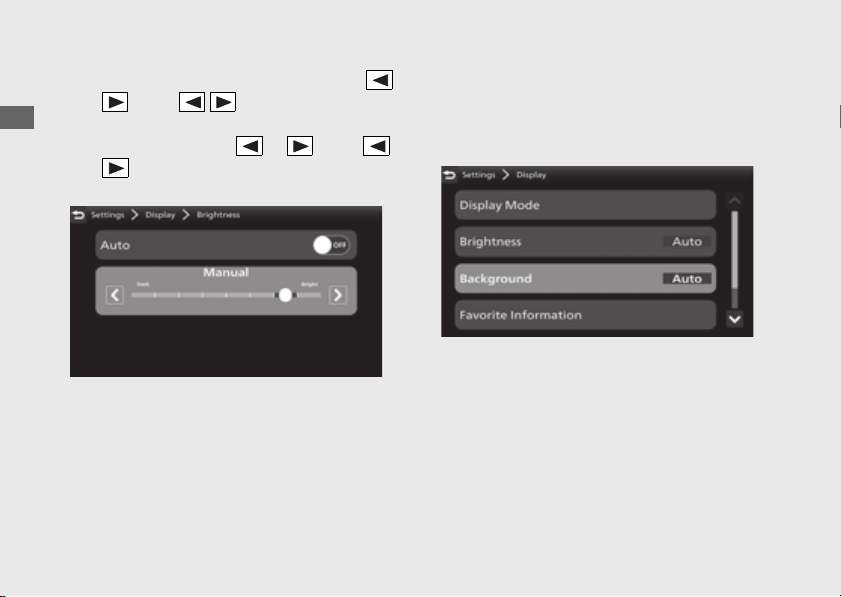
Operation Guide
!c If you select to [OFF] (manual) push the
or of the sel left/right switch to
select your preferred level.
u Push and hold the or of the
sel left/right switch to advance the
figure fast.
!d Return to the riding information, previous
screen or Home screen.
(P38)
You can also perform the above settings by
using the touch screen.
Setting range: Level 1 to 8 or [Auto]
Default: [Auto]
Background
You can select the background.
Automatic Background Control:
(P344)
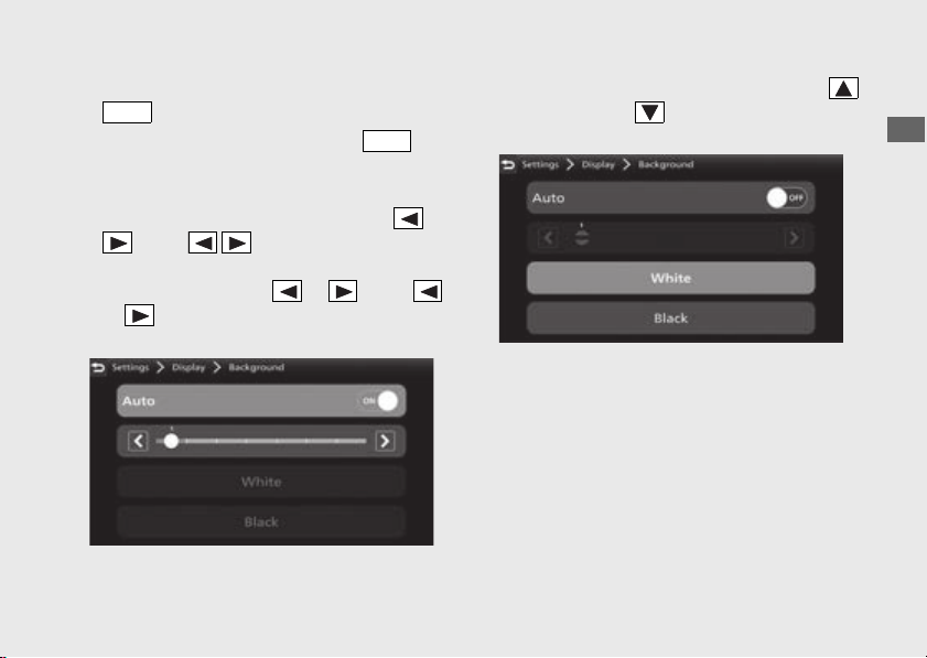
83
Operation Guide
Continued
!a Select [Background], and then press the
switch.
!b Select [Auto], and then press the
switch to [ON] (auto) or [OFF] (manual) the
function.
!c If you select to [ON] (auto), push the or
of the sel left/right switch to
select your preferred level.
u Push and hold the or of the
sel left/right switch to advance the
figure fast.
If you select to [OFF] (manual), press the
sel up switch or sel down switch to select
the [White] or [Black].
!d Return to the riding information, previous
screen or Home screen.
(P38)
You can also perform the above settings by
using the touch screen.
Setting range: Auto Level 1 to 7, White or
Black
Default: Auto 1
ENT
ENT
84
Instruments
(Continued)
Operation Guide
Favorite Information
You can select the following:
● Page 1
● Tripmeter A average fuel mileage [AVG.
CONS.]
● Tripmeter A average speed [AVG. SPD.]
● Tripmeter A current fuel mileage
[CONS.]
● Tripmeter A elapsed [ELAPSED]
● Tripmeter B [TRIP B]
● Blank
● Page 2
● Tripmeter B average fuel mileage [AVG.
CONS.]
● Tripmeter B average speed [AVG. SPD.]
● Tripmeter B current fuel mileage
[CONS.]
● Tripmeter B elapsed [ELAPSED]
● Blank
● Page 3
● Current fuel mileage [INST. CONS.]
● Available driving distance [RANGE]
● Battery voltage [VOLTAGE]
● Date [DATE]
● Average fuel mileage [AVG. CONS.]
● Fuel consumption [CONS.]
● Elapsed time [ELAPSED]
● Subtraction trip [-TRIP]
● Blank
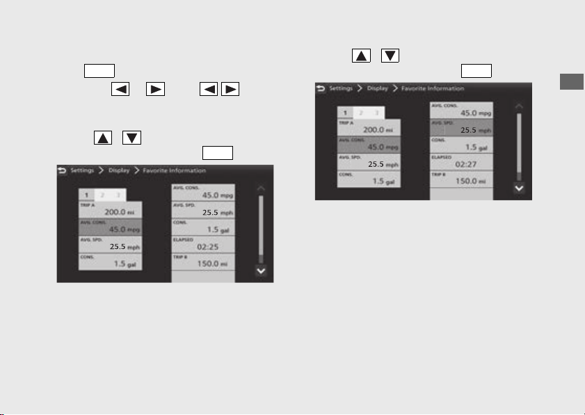
85
Operation Guide
Continued
!a Select [Favorite Information], and then press
the switch.
!b Push the or of the sel left/
right switch until the desired page is
displayed.
!c Press / to select the available
choices, and then press the switch.
!d Press / to select the available
choices, and then press the switch.
!e Return to the riding information, previous
screen or Home screen.
(P38)
You can also perform the above settings by
using the touch screen.
ENT
ENT
ENT

86
Instruments
(Continued)
Operation Guide
Default:
● Page 1
● Tripmeter A average fuel mileage [AVG.
CONS.]
● Tripmeter A average speed [AVG. SPD.]
● Tripmeter A current fuel mileage
[CONS.]
● Page 2
● Tripmeter B average fuel mileage [AVG.
CONS.]
● Tripmeter B average speed [AVG. SPD.]
● Tripmeter B current fuel mileage
[CONS.]
● Page 3
● Current fuel mileage [INST. CONS.]
● Available driving distance [RANGE]
● Battery voltage [VOLTAGE]
● Date [DATE]
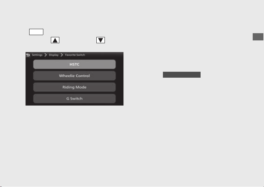
Favorite Switch
87
Operation Guide
Continued
!a Select [Favorite Switch], and then press the
switch.
!b Press the sel up switch or sel down
switch to select your desired mode.
!c Return to the riding information, previous
screen or Home screen. (P38)
You can also perform the above settings by
using the touch screen.
Available settings: [HSTC]/
[Wheelie Control]/[Riding Mode]/
[G Switch]
Default: [HSTC]
ENT
CRF1100D/D4
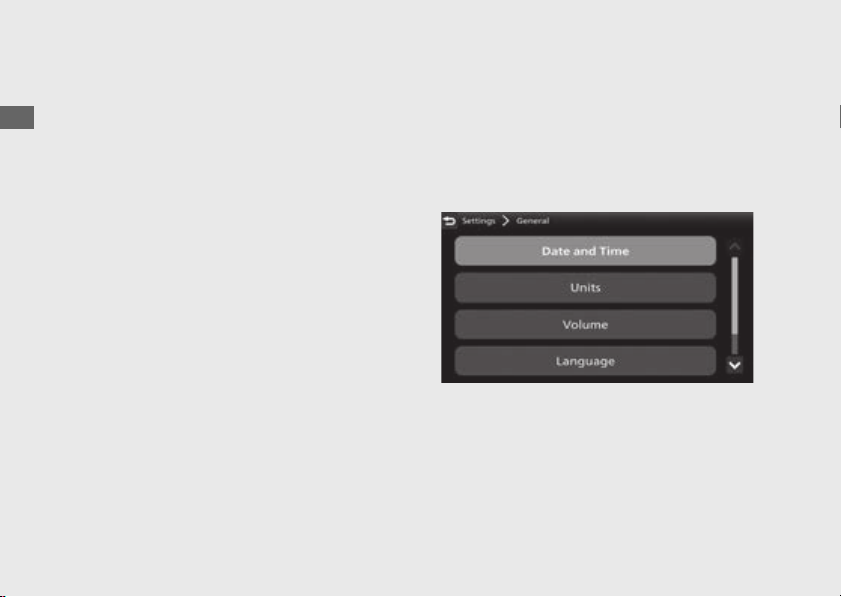
88
Instruments
(Continued)
Operation Guide
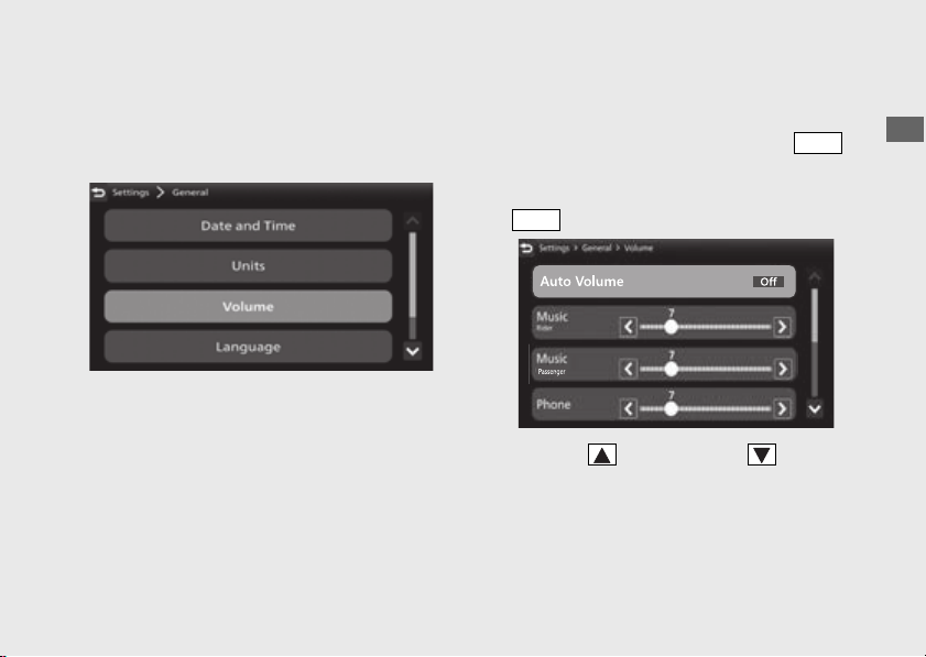
#
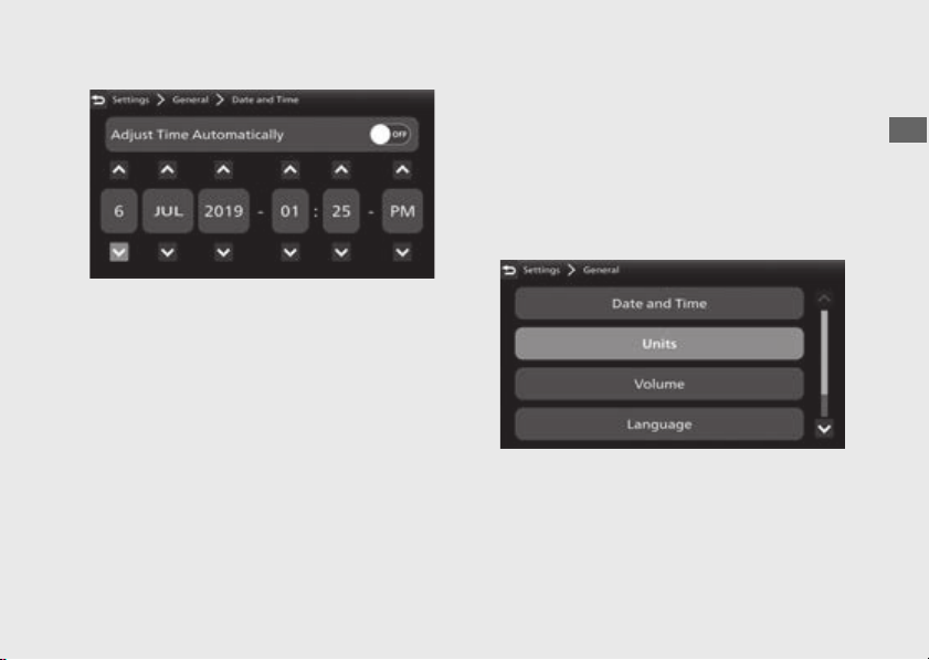
General
Following items can be changed sequentially.
● Date and Time (this page)
● Units
(P91)
● Volume (P93)
● Language (P95)
● Restore Default Setting (P96)
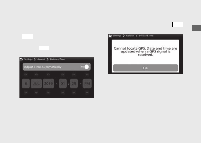
Date and Time
The multi-information display receives signals
from GPS satellites and updates the date and
time automatically.
You can also adjust the date and time
manually.
89
Operation Guide
Continued
To [ON] (auto) adjust time automatically
function:
!a Select [Date and Time], and then press the
switch.
!b Select [Adjust Time Automatically], and then
press the switch to [ON] (auto) the
function.
When GPS cannot be located. Read the
notice message, and then press the
switch.
!c Return to the riding information, previous
screen or Home screen.
(P38)
You can also perform the above settings by
using the touch screen.
ENT
ENT
ENT
90
Instruments
(Continued)
Operation Guide
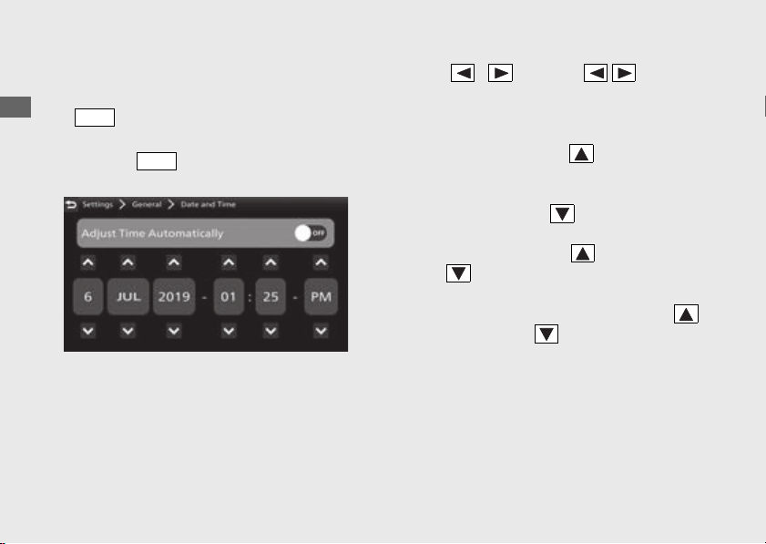
To adjust the clock manually:
!a Select [Date and Time], and then press the
switch.
!b Select [Adjust Time Automatically], and then
press the switch to [OFF] (manual) the
function.
!c Press / on the sel left/right
switch to select a day, month, year, hour,
minute or time format.
● To advance the day, month, year, hour
or minute: Press the sel up switch
until the desired value is displayed.
To delay the day, month, year, hour or
minute: Press the sel down switch
until the desired value is displayed.
u Press and hold the sel up switch or
sel down switch to advance the
figure fast.
● To select the time format: Press the
sel up switch or sel down switch until
the desired time format is displayed.
ENT
ENT
91
Operation Guide
Continued
!d Return to the riding information, previous
screen or Home screen.
(P38)
You can also perform the above settings by
using the touch screen.
Available settings: [ON] (auto)/[OFF]
(manual)
Default: [ON] (auto)
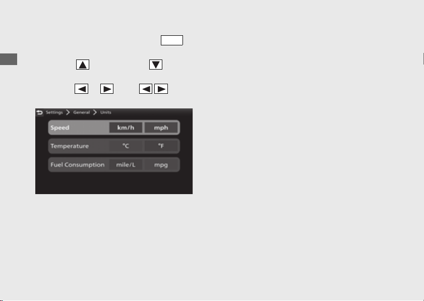
Units
You can change the following units.
● [Speed]: [mph] or [km/h]
● [Temperature]: [ºF] or [ºC]
● [Fuel Consumption]: [mpg] or [mile/L]
If the [km/h] for speed is selected, the fuel
mileage shown by [l/100 km] or [km/l].
92
Instruments
(Continued)
Operation Guide
!a Select [Units], and then press the
switch.
!b Press the sel up switch or sel down
switch to select a setting menu.
!c Push the or of the sel left/
right switch to select your desired unit.
!d Return to the riding information, previous
screen or Home screen.
(P38)
You can also perform the above settings by
using the touch screen.
Available settings:
● [Speed]: [mph]/[km/h]
● [Temperature]: [ºF]/[ºC]
● [Fuel Consumption]: [mpg]/[mile/L]/[l/100
km]/[km/l]
Default:
● [Speed]: [mph]
● [Temperature]: [ºF]
● [Fuel Consumption]: [mpg]
ENT
93
Operation Guide
Continued
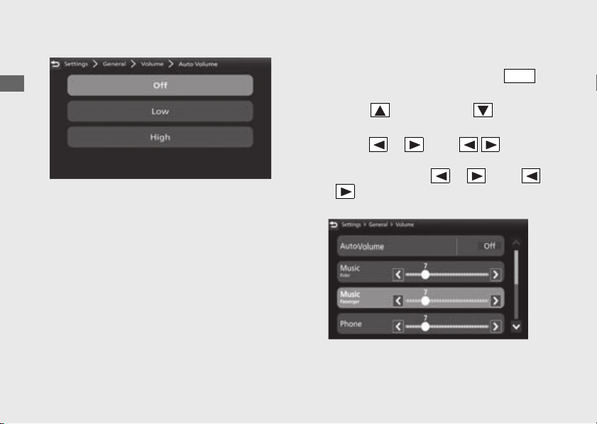
Volume
Selects the volume setting to automatically
increase volume from the headsets as the
speed of the vehicle increases.
To [Off] (disable), [Low] or [High] automatic
volume function:
!a Select [Volume], and then press the
switch.
!b Select [Auto Volume], and then press the
switch.
!c Press the sel up switch or sel down
switch to set your selection.
ENT
ENT
94
Instruments
(Continued)
Operation Guide
!d Return to the riding information, previous
screen or Home screen.
(P38)
You can also perform the above settings by
using the touch screen.
Available settings: [Off] (disable)/[Low]/
[High]
Default: [Off] (disable)
To adjust the volume:
!a Select [Volume], and then press the
switch.
!b Press the sel up switch or sel down
switch to select a setting menu.
!c Push the or of the sel left/
right switch to select your preferred level.
u Push and hold the or of the
sel left/right switch to advance the
figure fast.
ENT
95
Operation Guide
Continued
!d Return to the riding information, previous
screen or Home screen. (P38)
You can also perform the above settings by
using the touch screen.
VOLUME level range:
Other than Microphone: Level 0 to 30
Microphone: Level 0 to 14
Default:
● Music (Rider): 7
● Music (Passenger): 7
● Phone: 7
● System: 7
● Ringtone: 7
● Voice: 7
● CarPlay: 7
● Android Auto: 7
● Microphone: 7
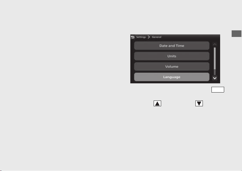
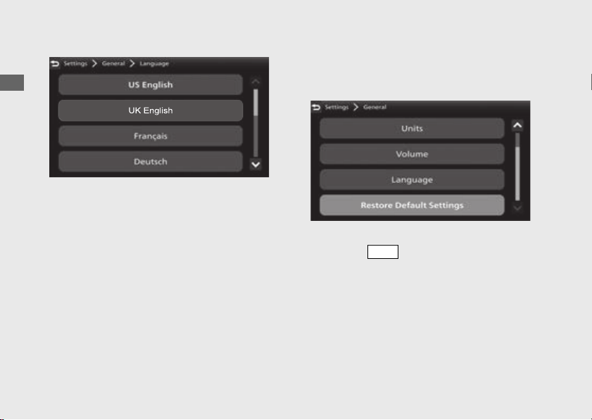
Language
Changes the system language.
!a Select [Language], and then press the
switch.
!b Press the sel up switch or sel down
switch to select the display language that you
want to use on the screen.
ENT
96
Instruments
(Continued)
Operation Guide
!c Return to the riding information, previous
screen or Home screen.
(P38)
You can also perform the above settings by
using the touch screen.
Default: [US English]
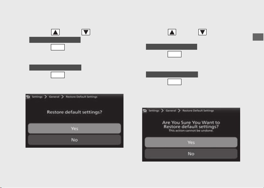
Restore Default Settings
The set values can be returned to default
settings.
!a Select [Restore Default Settings], and then
press the switch.
ENT
97
Operation Guide
Continued
!b Select [No] (not restore) or [Yes] (restore)
using the sel up or sel down switch.
!c
Press the switch.
The set value is maintained, and then the
display returns to the [General] menu screen.
Press the switch.
The display changes to the confirmation
screen.
!d Select [No] (not restore) or [Yes] (restore)
using the sel up or sel down switch
on the confirmation screen.
!e
Press the switch.
The set value is maintained, and then the
display returns to the [General] menu screen.
Press the switch.
The set value return to default setting, and
then the display returns to the [General]
menu screen.
When [No] is selected
ENT
When [Yes] is selected
ENT
When [No] is selected
ENT
When [Yes] is selected
ENT

98
Instruments
(Continued)
Operation Guide
!f Return to the riding information, previous
screen or Home screen. (P38)
You can also perform the above settings by
using the touch screen.
Default setting values:
● -TRIP: 000
● Display mode:
u [TOUR MODE]: Gold image
u [URBAN MODE]: Silver image
u [GRAVEL MODE]: Silver image
u [OFF ROAD MODE]: Bronze image
u [USER 1 MODE]: Silver image
u [USER 2 MODE]: Bronze image
● Brightness: Auto
● Background: Auto 1
● Favorite information:
u Page 1:
- Tripmeter A average fuel mileage
[AVG. CONS.]
- Tripmeter A average speed [AVG.
SPD.]
- Tripmeter A current fuel mileage
[CONS.]
u Page 2:
- Tripmeter B average fuel mileage
[AVG. CONS.]
- Tripmeter B average speed [AVG.
SPD.]
- Tripmeter B current fuel mileage
[CONS.]
u Page 3:
- Current fuel mileage [INST. CONS.]
- Available driving distance [RANGE]
- Battery voltage [VOLTAGE]
- Date [DATE]

99
Operation Guide
Continued
● Favorite switch: [HSTC]
● Auto Volume: [OFF]
● Periodic Maintenance:
● Distance: "-----"
● Date: "----/---"
● Oil Change:
● Distance: "-----"
● Date: "----/---"
● Delete the Bluetooth
®
paired device
#
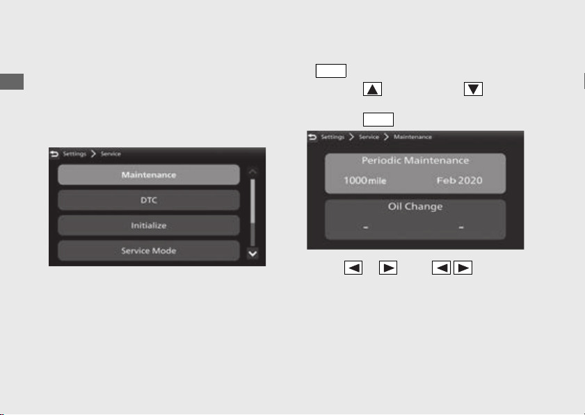
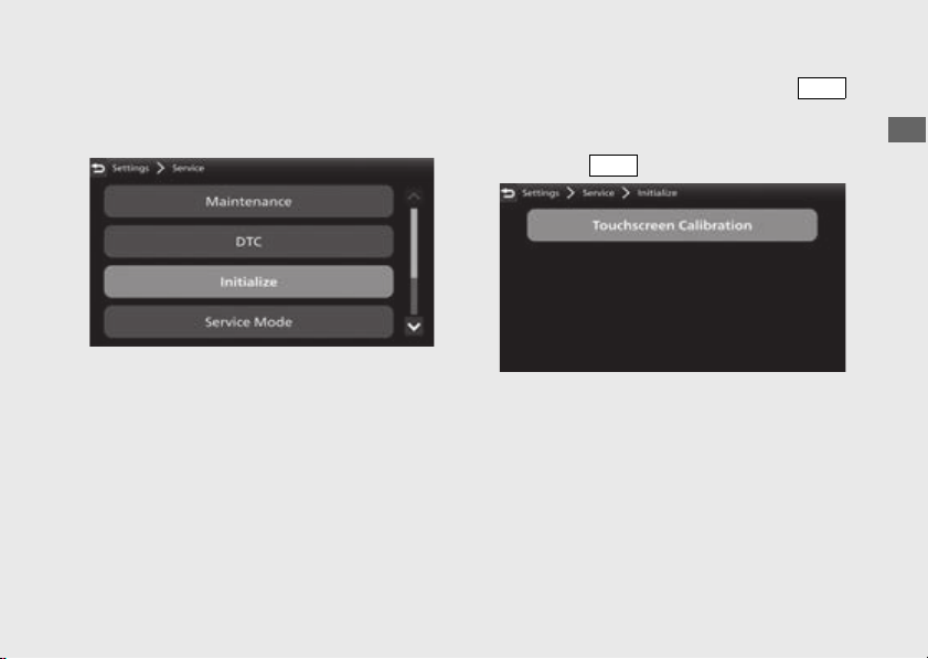
Service
Following items can be changed sequentially.
● Maintenance
(P100)
● DTC (P102)
● Initialize (P103)
● Service mode (P104)
● Equipment (P105)
● System Information (P105)
CRF1100A4/D4
100
Instruments
(Continued)
Operation Guide
Maintenance
You can check the next periodic inspection
time and next engine oil change.
You can change the setting of the next
periodic inspection and next engine oil
change.
!a Select [Maintenance], and then press the
switch.
!b Press the sel up switch or sel down
switch to select a setting menu, and then
press the switch.
!c Press or of the sel left/right
switch to select a distance, month or year
section.
ENT
ENT
101
Operation Guide
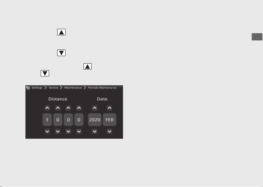
Continued
● To advance the distance, month or year:
Press the sel up switch until the
desired value is displayed.
To delay the distance, month or year:
Press the sel down switch until the
desired value is displayed.
u Press and hold the sel up switch or
sel down switch to advance the
figure fast.
!d Return to the riding information, previous
screen or Home screen.
(P38)
You can also perform the above settings by
using the touch screen.
Setting range:
● Periodic Maintenance:
● Distance: 100 to 4,000 mile or 100 to
6,400 km
● Date: 2000/JAN to 2099/DEC
● Oil Change:
● Distance: 100 to 8,000 mile or 100 to
12,800 km
● Date: 2000z/JAN to 2099/DEC
Default:
● Periodic Maintenance:
● Distance: "-----"
● Date: "----/---"
● Oil Change:
● Distance: "-----"
● Date: "----/---"
102
Instruments
(Continued)
Operation Guide
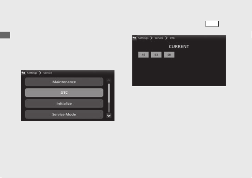
DTC
You can check for a current problem with the
PGM-FI system.
If your vehicle has problem, DTC index is
displayed.
Reduce speed and have your vehicle
inspected by your dealer as soon as possible.
!a Select [DTC], and then press the
switch.
!b Return to the riding information, previous
screen or Home screen.
(P38)
You can also perform the above settings by
using the touch screen.
ENT
103
Operation Guide
Continued
Initialize
You can calibrate the sensitivity of the touch
screen.
!a Select [Initialize], and then press the
switch.
!b Select [Touchscreen Calibration], and then
press the switch.
ENT
ENT

104
Instruments
(Continued)
Operation Guide
!c Touch the center on each of the four crosses.
u The screen flashes green when calibration
is complete.
If calibration fails, the screen flashes red.
Try step !c again.
!d Return to the riding information, previous
screen or Home screen.
(P38)
You can also perform the above settings by
using the touch screen.
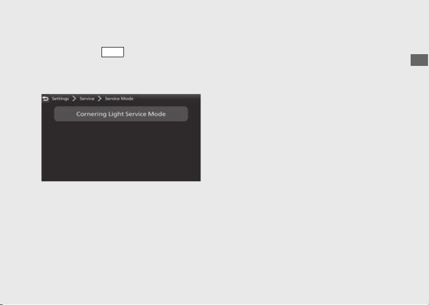
Service Mode
The cornering light can be turned on when
the vehicle is stopped for inspection.
!a Start the engine. (P218)
!b Stop the vehicle.
!c Select [Service Mode], and then press the
switch.
CRF1100A4/D4
ENT
105
Operation Guide
Continued
!d Select [Cornering Light Service Mode], and
then press the switch.
The cornering light lights up.
u The service mode will automatically stop in
5 minutes.
!e Return to the riding information, previous
screen or Home screen.
(P38)
You can also perform the above settings by
using the touch screen.
Equipment
This menu cannot be selected.
System Information
Shows various information of the multi-
information display.
● [Software Version]
● [Software update]: Cannot be selected.
● [Hardware Information]
● [GPS Reception Status]
● [EULAs]
● [Copyright and Acknowledgements]
#
Regulatory
Shows regulatory information of the multi-
information display.
ENT
106
Instruments
(Continued)
Operation Guide
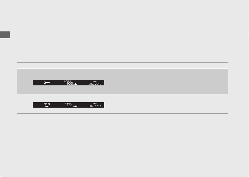
Pop-up information
In the following cases, pop-up information is displayed at the bottom of the multi-information
display.
● Maintenance information:
When the inspection time of your vehicle is approaching.
Maintenance information
Indication Explanation Remedy
When the periodic
inspection time of
your vehicle is
approaching
Have your vehicle
inspected by your
dealer.
When the oil change
time of your vehicle is
approaching
Change the engine oil.

107
Operation Guide
This page intentionally left blank.
108
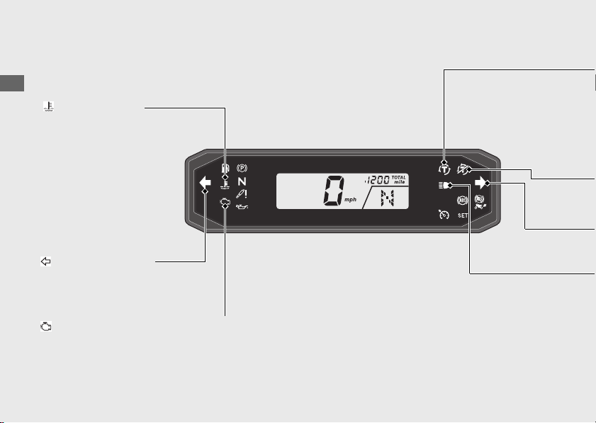
Operation Guide
Indicators
If one of these indicators does not come on when it should, have your
dealer check for problems.
Left turn signal
indicator
PGM-FI (Programmed Fuel Injection) malfunction indicator lamp (MIL)
High coolant
temperature indicator
Comes on briefly when the
ignition switch is turned to
the ON position.
If it comes on while
riding:
(P309)
Comes on briefly when the ignition switch is turned to the ON position.
If it comes on while engine is running:
(P310)

109
Continued
Operation Guide
High beam indicator
If it comes on while riding: (P312)
Torque Control indicator
● Comes on when the ignition switch is turned to the ON position. Goes off
when your speed reaches approximately 3 mph (5 km/h) to indicate Torque
Control is ready to work.
● Blinks when Torque Control is operating.
Torque Control OFF Indicator
● Comes on when the Torque Control is turned Off.
Right turn signal indicator

110
Indicators
(Continued)
Operation Guide
Low fuel indicator
If the indicator comes on and the fuel gauge indicator flashes: (P314)
● Comes on when there is only reserve fuel left in the fuel tank.
Remaining fuel when low fuel indicator comes on:
Approximately 0.95 US gal (3.6 L)
Approximately 1.03 US gal (3.9 L)
CRF1100A/D
CRF1100A4/D4
● Comes on briefly when the ignition switch is turned to the ON position.
Parking brake indicator
Lights as a reminder that you
have not released the parking
brake lever.
CRF1100D/D4
Comes on when the
transmission is in Neutral.
Neutral indicator

111
Continued
Operation Guide
ABS (Anti-lock Brake System) indicator
If it comes on while riding: (P311)
● Goes off when your speed reaches approximately 6 mph (10 km/h).
● Comes on briefly when the ignition switch is turned to the ON position.
Rear ABS (Anti-lock Brake System) OFF Indicator
● Comes on briefly when the ignition switch is turned to the ON position.
● Comes on when the ABS function on the rear wheel is turned off.
(P120)
Cruise control SET indicator
Comes on if you have set a speed for cruise control.
Cruise Control:
(P230)
SET
Cruise control main indicator
Comes on when you press cruise control main switch.
Cruise Control:
(P230)
112
Indicators
(Continued)
Operation Guide
Low oil pressure indicator
If it comes on while engine is running: (P310)
● Comes on when the ignition switch is turned to the ON position.
● Goes off when the engine starts.
Suspension indicator
CRF1100A4/D4
● Comes on when the suspension initialization is waiting.
● Stop your vehicle and wait for a few seconds until the indicator turns off.
If indicator dose not turn off, contact your dealer.

113
Operation Guide
This page intentionally left blank.
114
Operation Guide
Switches
Turns electrical system
on for starting/riding.
Turns engine off.
OFF
ON
LOCK
Locks steering.
Steering Lock:
(P119)
u Key can be removed when in
the OFF or LOCK position.
Switches the electrical system on/off,
locks the steering.
Ignition switch
Left handlebar
switch (P116)
Right handlebar
switch (P115)
115
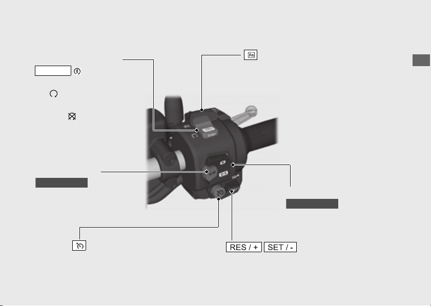
Operation Guide
Continued
Engine stop switch/
button
START
u In an emergency, switch
to the (Stop) position
to stop the engine.
Should normally remain in
the (Run) position.
Function sel switch
Press to display the pop-up information
on the multi-information display.
AT/MT switch
To shift between the AT
MODE and MT MODE.
(P227)
CRF1100D/D4
N-D switch
To shift between Neutral and
AT MODE.
(P227)
CRF1100D/D4
Cruise control main switch
Press to activate the cruise control
system.
(P230)
Cruise control lever
Push up or down to set the speed or adjust
the set speed.
(P232)
#
Right handlebar switch
u To start the engine.
(P218)
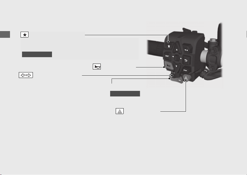
116
Switches
(Continued)
Operation Guide
Horn button
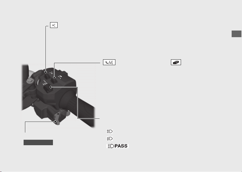
#
Left handlebar switch
Favorite switch
Turn signal switch
The turn signal will automatically stop
when you complete the turn. (You can
manually cancel the lights by pressing
the switch in.) When used for a lane
change, the turn signal will
automatically stop in 7 seconds or
after riding 131 yards (120 m). In some
cases, the timing at which the turn
signal stops could be less or more.
Always use the recommended tires to
ensure correct automatic cancellation
operation.
Hazard switch
Switchable when the ignition switch is turned to
the ON position. Can be turned to off regardless
of the ignition switch position.
u The signals continue flashing with the ignition
switch in OFF or LOCK after the hazard switch
is on.
Shift down switch (-)
To shift down the gear. (P229)
CRF1100D/D4
Favorite switch can be assigned to the HSTC switch,
wheelie control switch, riding mode switch or G switch
( ).
(P86)
CRF1100D/D4
117
Continued
Operation Guide
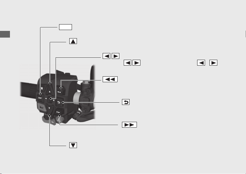
Shift up switch (+)
To shift up the gear.
(P229)
CRF1100D/D4
● Pull backward to return to the riding information or
audio screen.
(P38)
●
Pull backward and hold to go to the Home screen, Apple
CarPlay screen or
Android Auto
screen.
(P36)
●
Push forward to receive, reject or end a call.
(P187)
●
Push forward to start Siri or voice search when Apple CarPlay or
Android Auto
is available.
(P202)
(P216)
Function lever
Headlight dimmer/Passing
light control switch
● : High beam
● : Low beam
● : Flashes the high beam headlight.
● Push forward or pull backward to adjust the audio system volume. (P153)
● Push forward or pull backward to adjust the grip heater level. (P129)
Voice control switch / Page switch
118
Switches
(Continued)
Operation Guide
Sel up switch
Press the sel up switch to select the available choices. (P37)
Sel down switch
Press the sel down switch to select the available choices. (P37)
switch
Press to set your selection. (P37)
ENT
Sel left/right switch
Press the sel left/right switch in the /
directions to select the available choices.
(P37)
Skip switch
Skips to the next song or to move rapidly
within a track.
(P176)
Back switch
Press to return to the previous screen.
(P38)
Goes back switch
Goes back to the beginning of the current or previous
song or to move rapidly within a track.
(P176)
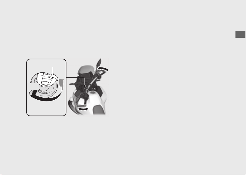
119
Operation Guide
Steering Lock
Lock the steering when parking to help
prevent theft.
A U-shaped wheel lock or similar device is also
recommended.
#
Locking
!a Turn the handlebar all the way to the left.
!b Push the key down, and turn the ignition
switch to the LOCK position.
u Jiggle the handlebar if the lock is difficult
to engage.
!c Remove the key.
#
Unlocking
Insert the key, push it in, and turn the ignition
switch to the OFF position.
Ignition key
Turn
!a
!b
Push

120
Operation Guide
ABS function on the rear wheel
The ABS function on the rear wheel can be
optionally turned off for off-road riding.
You can turn off the rear wheel ABS function
in [OFF ROAD MODE], [USER 1 MODE] or
[USER 2 MODE].
u Each time the ignition switch is turned to the
ON position, the ABS function on both wheels
will automatically be turned on [ACTIVE], but
the ABS will maintain the rear wheel [CANCEL]
off-function when engine stopped by using
the engine stop switch.
u Select [ON ROAD] of ABS mode [ABS], the
ABS function on both wheels [ABS RR] will
automatically be turned on [ACTIVE].
u When changing the riding mode, the ABS
function on both wheels will automatically be
turned on [ACTIVE].
To turn off the ABS function on the rear
wheel
!a Stop the vehicle and close the throttle
completely.
!b Select [OFF ROAD MODE], [USER 1 MODE]
or [USER 2 MODE] mode of riding mode.
(P145)
If [USER 1 MODE] or [USER 2 MODE] is
selected, select [OFF ROAD] for ABS mode
[ABS].
(P75)
!c Select the gold image display. (P79)
!d Select page 4. (P43)
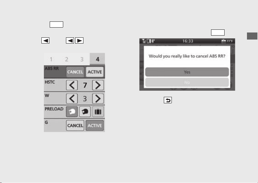
121
Operation Guide
Continued
!e Press the switch.
!f Select [ABS RR].
!g Press on the sel left/right switch
to select [CANCEL] (off).
!h Read the notice message.
!i Select [Yes], and then press the switch.
!j Press the back switch.
u The rear ABS OFF indicator is on, when the
ABS function on the rear wheel [ABS RR] is
turned [CANCEL] (off).
You can also perform the above settings by
using the touch screen.
ENT
ENT
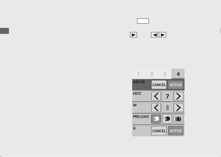
122
ABS function on the rear wheel
(Continued)
Operation Guide
To turn on the ABS function on both
wheels
!a Stop the vehicle and close the throttle
completely.
!b Select the gold image display. (P79)
!c Select page 4. (P43)
!d Press the switch.
!e Select [ABS RR].
!f Press on the sel left/right switch
to select [ACTIVE] (on).
u The rear ABS OFF indicator flashes several
times, and then off, when the ABS function
on the rear wheel [ABS RR] is turned on
[ACTIVE].
ENT
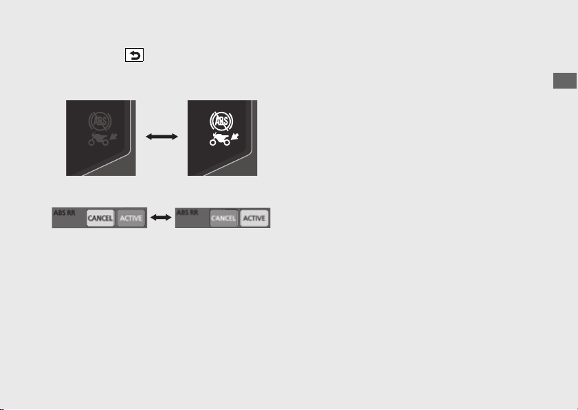
123
Operation Guide
!g Press the back switch.
You can also perform the above settings
by using the touch screen.
Available settings: [ACTIVE]/[CANCEL]
Default: [ACTIVE]
ABS function on
both wheels is
[ACTIVE] (on).
ABS function on
rear wheel is
[CANCEL] (off).
When the gold image is selected:
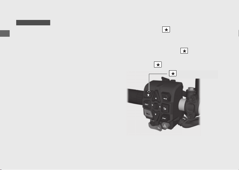
124
Operation Guide
G switch
The G switch can change the engine
characteristics of your vehicle to help improve
traction and machine control for off-road riding
by reducing the amount of clutch slip during
throttle operation.
u Other than USER 1 and USER 2 MODE
Each time the ignition switch is turned to the
ON position, the G switch [G] will
automatically be set to default setting.
USER 1 and USER 2 MODE
The G switch [G] setting will be maintained
even if the ignition switch is turned to the OFF
position.
u The G switch [G] may not compensate for
rough road conditions.
Always consider road and weather
conditions, as well as your skills and condition,
when applying throttle.
G switch on or off
● When using the favorite switch.
!a Stop the vehicle and close the throttle
completely.
!b Select [G Switch] of the favorite switch.
(P86)
!c Press the favorite switch.
CRF1100D/D4
Favorite switch
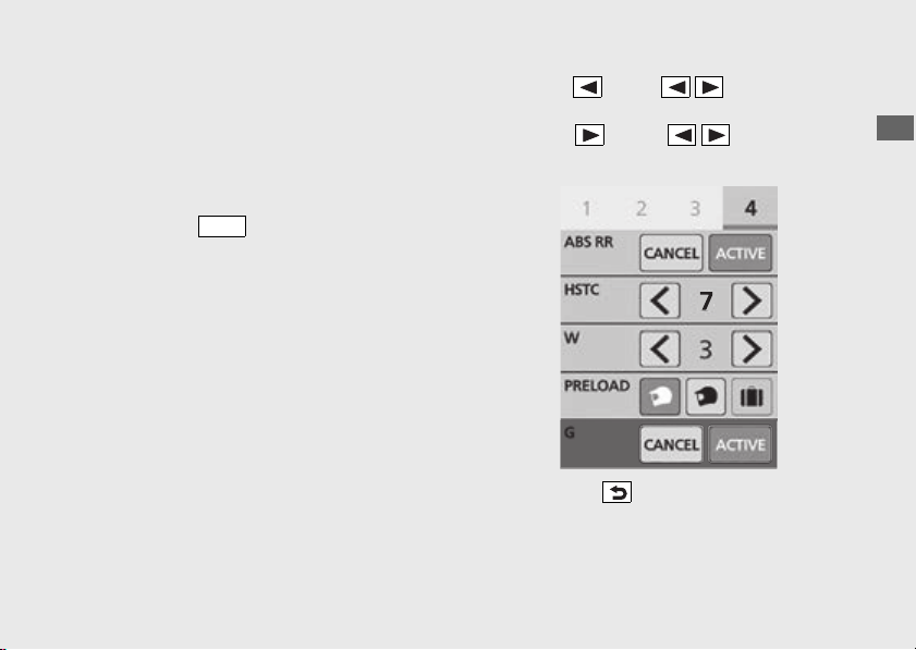
125
Operation Guide
Continued
● When using the multi-information display:
!a Stop the vehicle and close the throttle
completely.
!b Select the gold image display. (P79)
!c Select page 4. (P43)
!d Press the switch.
!e Select [G].
!f Press on the sel left/right
switch to select [CANCEL] (off).
Press on the sel left/right
switch to select [ACTIVE] (on).
!g Press the back switch.
You can also perform the above settings
by using the touch screen.
ENT
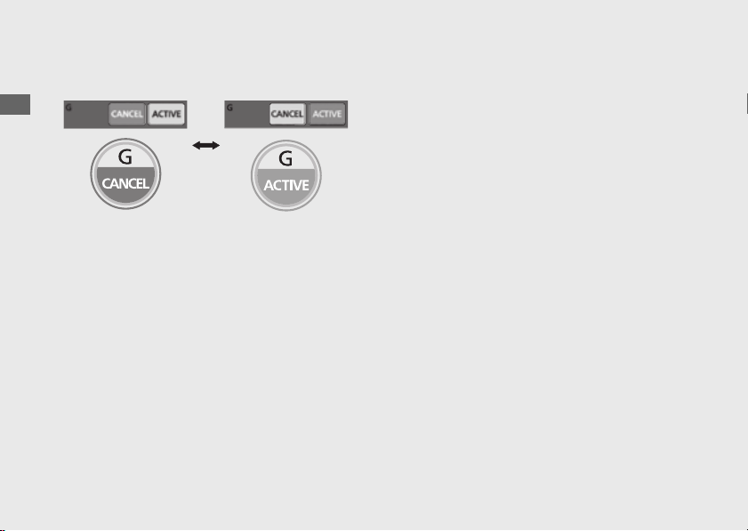
126
G switch
(Continued)
Operation Guide
Available settings: [ACTIVE]/[CANCEL]
Default:
● [TOUR MODE]: [CANCEL]
● [URBAN MODE]: [CANCEL]
● [GRAVEL MODE]: [CANCEL]
● [OFF ROAD MODE]: [ACTIVE]
● [USER 1 MODE]: [CANCEL]
● [USER 2 MODE]: [CANCEL]
G switch [G]
[CANCEL] (off)
G switch [G]
[ACTIVE] (on)
When the gold image is selected:
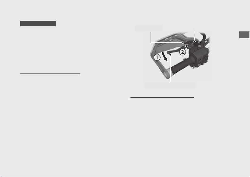
127
Operation Guide
Parking Brake
Parking Brake Lever
Be sure the parking brake is applied while
parking and warming up the engine.
u Make sure the parking brake lever is released
before riding.
To apply the parking brake
Squeeze the parking brake lever (!a) fully
then rotate the lock lever (!b) clockwise until
it engages the slot on the parking brake lever
bracket back to lock the rear wheel.
u The parking brake lock will not function if the
parking brake is not adjusted properly.
(P283)
To release the parking brake
Squeeze the parking brake lever until the lock
lever is released from the slot on the parking
brake lever bracket.
u Before riding, check that the parking brake
indicator is turned off and make sure that the
parking brake is fully released so there is no
drag on the rear wheel.
CRF1100D/D4
Lock lever
Parking brake lever
Slot
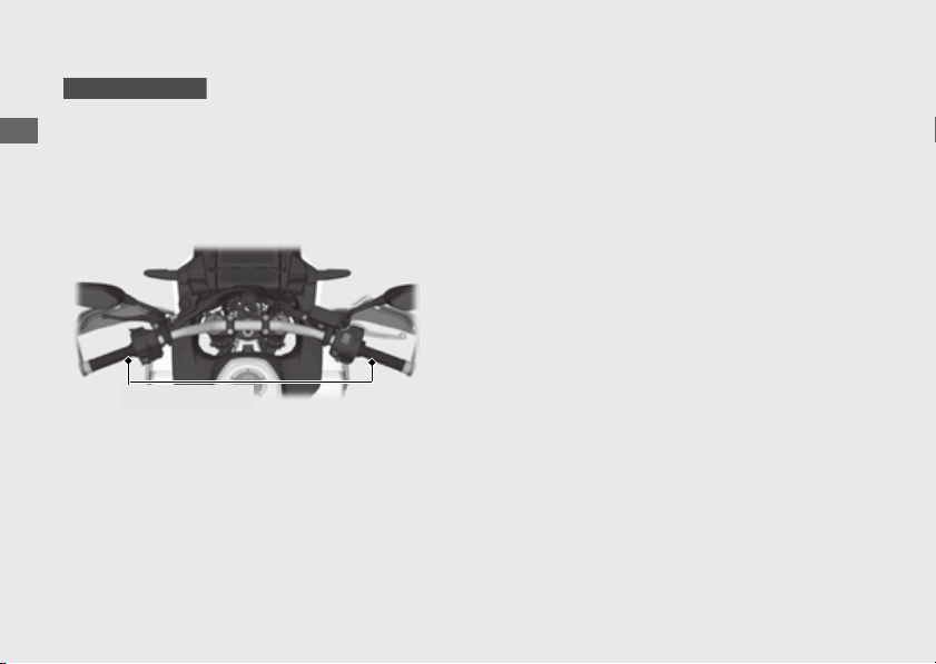
128
Operation Guide
Handle Grip Heater
This vehicle is equipped with a handle grip
heater that warms up your hands during your
ride.
Wear gloves to protect your hands from the
heated grips.
Handle grip heater indicator:
Comes on when the handle grip heater is on
and indicates the selected heat level. The
handle grip heater have 5 levels of heat to
select.
Handle grip heater status icon:
(P130)
Displayed when the handle grip heater is on.
CRF1100A4/D4
Handle grips
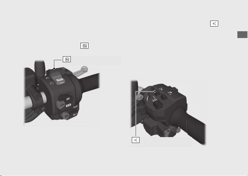
129
Operation Guide
Continued
#
To operate handle grip heater
!a Start the engine. (P218)
!b Select the handle grip heater display of pop-
up information using the function sel
switch.
!c Push forward or pull backward the
function lever to select the handle grip heater
level.
u The status icon will be appeared on the
display when the handle grip heater
operates.
u Do not leave the handle grip heater in the
high position for a long time on a warm
day.
Function sel switch
Function lever
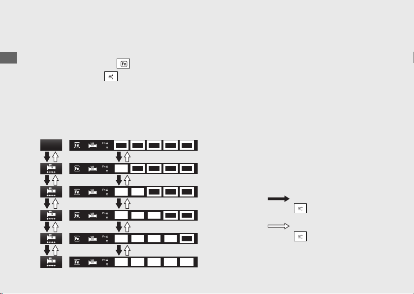
130
Handle Grip Heater
(Continued)
Operation Guide
#
To turn off handle grip heater
!a Select the handle grip heater display pop-up
information using the function sel switch.
!b Pull backward the function lever several
times to select the handle grip heater off.
Do not use the handle grip heater with the
engine at idle for a long time. It may result in
a low (or dead) battery.
Maintains the selected level when the ignition
switch is turned to the OFF position.
u The heater level is not changed if the ignition
switch is turned to the OFF position within 5
seconds after heater level changed.
No indication (Off)
lowest temperature
highest temperature
Level 1
Level 2
Level 3
Level 4
Level 5
Pull backward the
function lever
Push forward the
function lever

131
Continued
Operation Guide
Honda Selectable Torque Control
Torque Control level (engine power control)
can be selected or turned on/off.
u Do not change the Torque Control level while
riding.
Stop the vehicle first, turn the Torque Control
off or on and select the desired level.
u The Torque Control setting cannot be
changed or turned off when the system is
activated (Torque Control indicator flashing).
u In the following cases, the Torque Control will
be turned on and the specific Torque Control
level will automatically be set as below.
● Each time the ignition switch is turned to
the ON position, the Torque Control
level will automatically be set to level it
was set to. However, if the level was set
to [0] (off), it will become level 1.
u When the Torque Control is turned from the
[0] (off) position to the on position, it will
automatically be set to level of before turning
off the Torque Control.
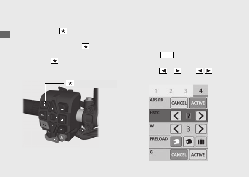
132
Honda Selectable Torque Control
(Continued)
Operation Guide
Torque Control level setting
● When using the favorite switch:
!a Stop the vehicle.
!b Select the [HSTC] of the favorite
switch. (P86)
!c Press the favorite switch.
u 7: the maximum Torque Control level
u 1: the minimum Torque Control level
● When using the multi-information display:
!a Stop the vehicle.
!b Select the gold image display.
(P79)
!c Select page 4. (P43)
!d Press the switch.
!e Select [HSTC].
!f Push the or of the sel left/
right switch to select your preferred level.
Favorite switch
ENT
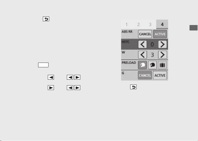
133
Operation Guide
Continued
!g Press the back switch.
You can also perform the above settings
by using the touch screen.
Torque Control on and off
!a Stop the vehicle.
!b Select the gold image display.
(P79)
!c Select page 4. (P43)
!d Press the switch.
!e Select [HSTC].
!f Press and hold on the sel left/
right switch to set the [0] (off).
Press and hold on the sel left/
right switch to set to level of before turning
[0] (off) the Torque Control.
!g Press the back switch.
You can also perform the above settings
by using the touch screen.
Setting range: Level 1 to 7 or 0 (Off)
ENT
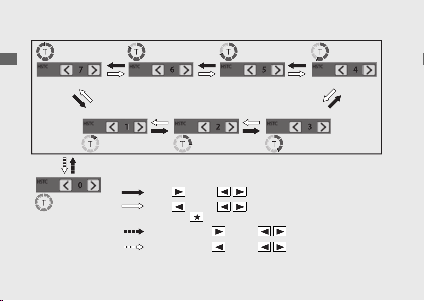
134
Honda Selectable Torque Control
(Continued)
Operation Guide
Level [2]
[0] (Off)
Push on the sel left/right switch
Push and hold on the sel left/right switch
Push on the sel left/right switch or
press the favorite switch
Push and hold on the sel left/right switch
Level [1] Level [3]
Level [7] Level [6] Level [5] Level [4]

135
Continued
Operation Guide
Wheelie Control
Wheelie Control level [W] can be selected or
turned on/off.
u Do not change the wheelie control level [W]
while riding.
Stop the vehicle first, then select the wheelie
control level [W].
u In the following cases, the wheelie control [W]
will be turned on and the specific wheelie
control level [W] will automatically be set as
below.
● Each time the ignition switch is turned to
the ON position, the wheelie control
level [W] will automatically be set to level
it was set to before. However, if the level
was set to 0 (off), it will automatically be
set to level before turning off the
wheelie control level [W].
u When the wheelie control [W] is turned from
the [0] (off) position to the on position, it will
automatically be set to the level before
turning off the wheelie control [W].
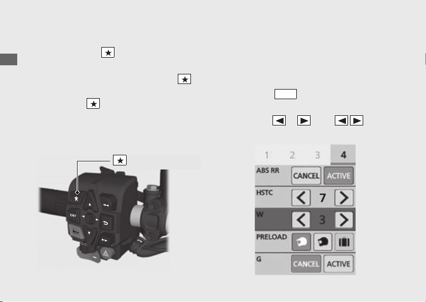
136
Wheelie Control
(Continued)
Operation Guide
Wheelie Control Level setting
● When using the favorite switch:
!a Stop the vehicle.
!b Select the [Wheelie Control] of the
favorite switch. (P86)
!c Press the favorite switch.
u 3: the maximum wheelie control level
[W]
u 1: the minimum wheelie control level
[W]
● When using the multi-information display:
!a Stop the vehicle.
!b Select the gold image display.
(P79)
!c Select page 4. (P43)
!d Press the switch.
!e Select [W].
!f Push the or of the sel left/
right switch to select your preferred level.
Favorite switch
ENT
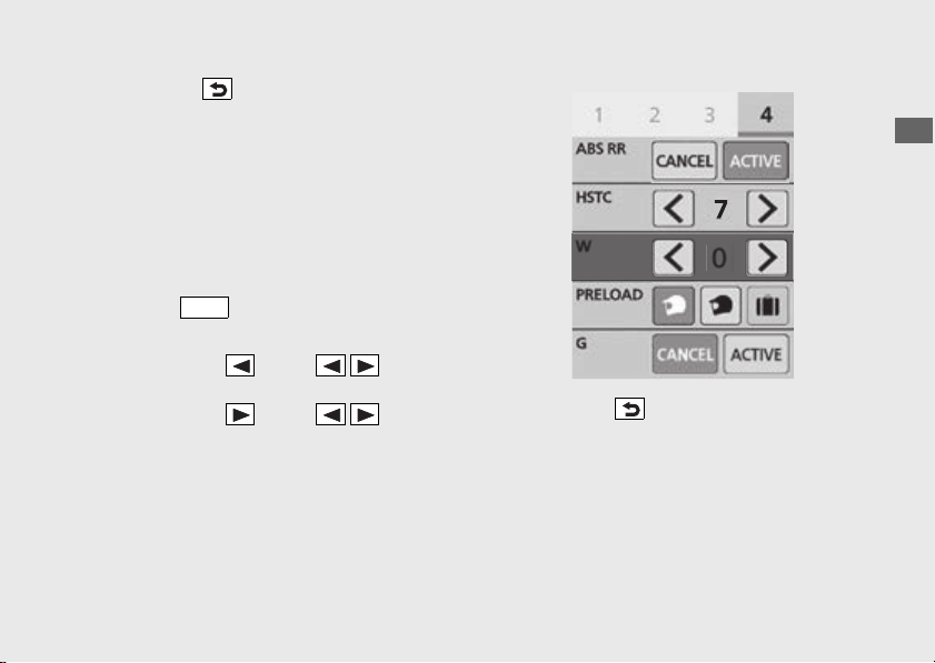
137
Operation Guide
Continued
!g Press the back switch.
You can also perform the above settings by
using the touch screen.
Wheelie Control on and off
!a Stop the vehicle.
!b Select the gold image display.
(P79)
!c Select page 4. (P43)
!d Press the switch.
!e Select [W].
!f Press and hold on the sel left/
right switch to set the [0] (off).
Press and hold on the sel left/
right switch to set to level of before turning
[0] (off) the wheelie control.
!g Press the back switch.
You can also perform the above settings by
using the touch screen.
Setting range: Level 1 to 3 or 0 (Off)
ENT
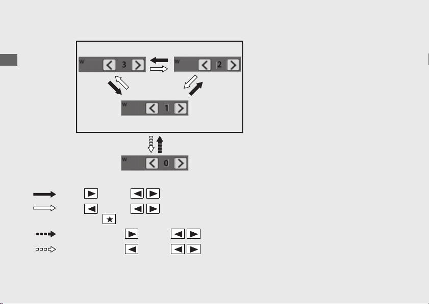
138
Wheelie Control
(Continued)
Operation Guide
Level [2]
[0] (Off)
Push on the sel left/right switch
Push and hold on the sel left/right switch
Push on the sel left/right switch or
press the favorite switch
Push and hold on the sel left/right switch
Level [1]
Level [3]

139
Continued
Operation Guide
Riding mode
You can change the riding mode.
The riding mode consists of the following
parameters.
[P] Power: Engine output level
[EB] Engine brake: Engine brake level
[ABS] ABS mode:
● [OFF ROAD]: Off road mode
● [ON ROAD]: On road mode
[S] [Overall]: Suspension damping
[Front]: Suspension damping
[Rear]: Suspension damping
[G] G switch:
(P124)
[PRELOAD] [Preload]: Rear suspension
preload
● (Rider): Rider only (Minimum preload)
● (Rider+Cargo): Rider and luggage
● (Rider+Passenger): Rider and passenger
● (Rider+Passenger+Cargo): Rider,
passenger and luggage (Maximum
preload)
CRF1100A4/D4
CRF1100D/D4
CRF1100A4/D4
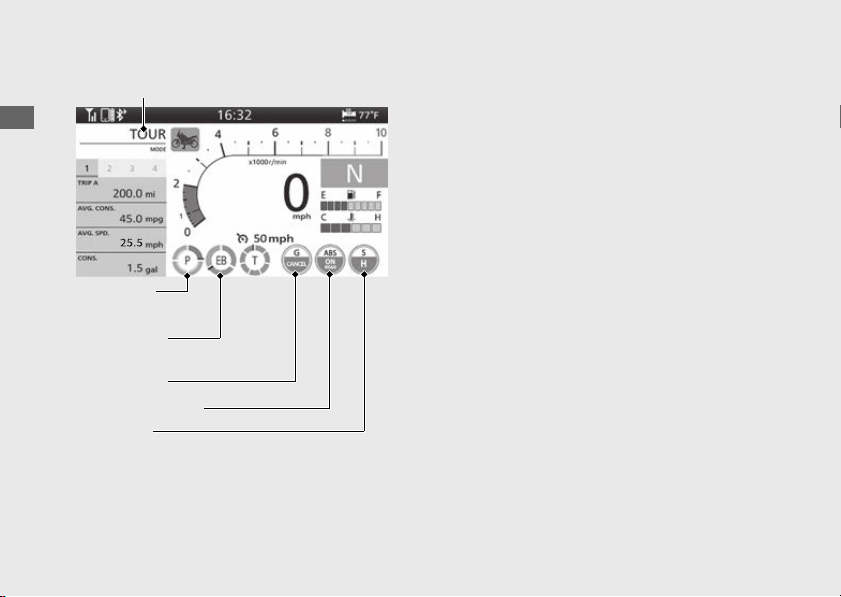
140
Riding mode
(Continued)
Operation Guide
Riding mode has 6 modes.
Available riding modes: [TOUR MODE],
[URBAN MODE], [GRAVEL MODE], [OFF
ROAD MODE], [USER 1 MODE] and [USER 2
MODE]
[TOUR MODE], [URBAN MODE], [GRAVEL
MODE] and [OFF ROAD MODE]
u [TOUR MODE]: Enables smooth acceleration
even when riding with a passenger or a full
load of luggage.
u [URBAN MODE]: Standard, all-round mode
for a variety of situations.
u [GRAVEL MODE]: Good for stable riding on
slippery surfaces such as dirt roads.
u [OFF ROAD MODE]: Suitable for enjoying
off-road sports riding.
Each initial setting value cannot be changed.
[USER 1 MODE] and [USER 2 MODE]
Each initial setting value can be changed.
Current riding mode
[P] [Power]
value
[G] G switch
[EB] [Engine
Brake] value
[ABS] ABS mode
[S] Overall

141
Operation Guide
Continued
Initial setting
Riding modes
[P]
[Power]
value
[EB]
[Engine
Brake]
value
Suspension damping
[ABS] ABS
mode
[G] G
switch
*2
[S]
[Overall]
*1
[Front]
*1
[Rear]
*1
[TOUR MODE]
1 2 H Medium Medium ON ROAD CANCEL
*3
[URBAN MODE]
2 2 M Medium Medium ON ROAD CANCEL
*3
[GRAVEL MODE]
4 3 S Medium Medium OFF ROAD CANCEL
*3
[OFF ROAD MODE]
3 3 O Medium Medium OFF ROAD ACTIVE
*3
[USER 1 MODE]
2
*3
2
*3
M
*3
Medium
*3
Medium
*3
ON ROAD
*3
CANCEL
*3
[USER 2 MODE]
4
*3
3
*3
S
*3
Medium
*3
Medium
*3
OFF ROAD
*3
CANCEL
*3
Notes:
*1 :
*2 :
*3 : Value can be changed.
CRF1100A4/D4
CRF1100D/D4
142
Riding mode
(Continued)
Operation Guide
Riding modes
[PRELOAD]
[Preload]
(Rider)
*1
[PRELOAD]
[Preload]
(Rider+Cargo)
*1
[PRELOAD]
[Preload]
(Rider+
Passenger)
*1
[PRELOAD]
[Preload]
(Rider+
Passenger+
Cargo)
*1
[TOUR MODE]
5 101520
[URBAN MODE]
5 10 15 20
[GRAVEL MODE]
5 101520
[OFF ROAD MODE]
5 10 15 20
[USER 1 MODE]
5
*2
10
*2
15
*2
20
*2
[USER 2 MODE]
5
*2
10
*2
15
*2
20
*2
Notes:
*1 :
*2 : Value can be changed.
CRF1100A4/D4

143
Operation Guide
Continued
[P] Power value (Engine output level)
[P] Power value has four setting levels.
Available setting range: 1 to 4
u Level 1 has the maximum power.
u Level 4 has the minimum power.
[EB] Engine brake value (Engine brake
level)
EB value has three setting levels.
Available setting range: 1 to 3
u Level 1 has the strongest engine braking
effect.
u Level 3 has the weakest engine braking effect.
[S] Overall: suspension damping
[S] Overall value has four setting levels.
Available setting range: [H] Hard / [M]
Medium / [S] Soft / [O] Off Road
u [H] Hard has the maximum suspension
damping.
u [S] Soft has the minimum suspension
damping.
u [O] Off Road is for off road settings.
[Front]: suspension damping
[Front] has three setting levels.
Available setting range: - / Medium / +
u + has the maximum suspension damping.
u - has the minimum suspension damping.
CRF1100A4/D4
CRF1100A4/D4

144
Riding mode
(Continued)
Operation Guide
[Rear]: suspension damping
[Rear] has three setting levels.
Available setting range: - / Medium / +
u + has the maximum suspension damping.
u - has the minimum suspension damping.
ABS mode [ABS]
ABS mode [ABS] has two setting levels.
Available setting range: [OFF ROAD] or [ON
ROAD]
u [OFF ROAD] is for off road settings.
u [ON ROAD] is for on road settings.
[G] G switch (P124)
[PRELOAD] [Preload] (Rider),
(Rider+Cargo), (Rider+Passenger) and
(Rider+Passenger+Cargo): rear
suspension preload
[PRELOAD] [Preload] Preload has twenty four
setting levels.
Available setting range: 1 to 24
u Level 24 has the maximum suspension
preload.
u Level 1 has the minimum suspension preload.
CRF1100A4/D4
CRF1100D/D4
CRF1100A4/D4
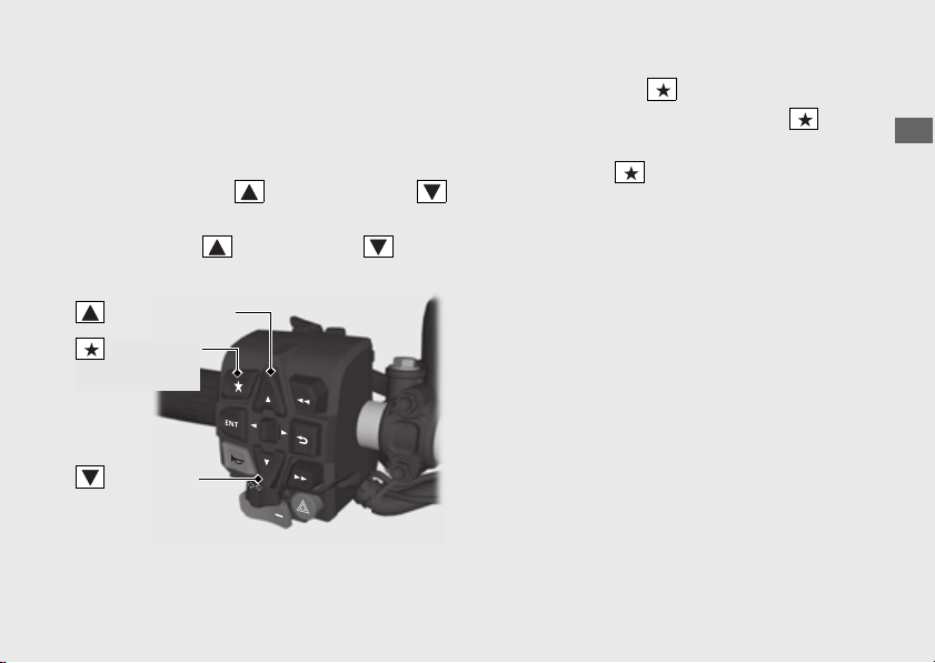
145
Operation Guide
Continued
Selecting the riding mode
When changing the riding mode, the rear
wheel ABS function [ABS RR] will automatically
be set to [ACTIVE].
● When using the sel up switch and
sel down switch:
!a Press the sel up switch or sel
down switch.
You can also perform the above settings by
using the touch screen.
● When using the favorite switch:
!a Select the [Riding Mode] of the
favorite switch.
(P86)
!b Press the favorite switch.
sel up switch
sel down
switch
Favorite
switch
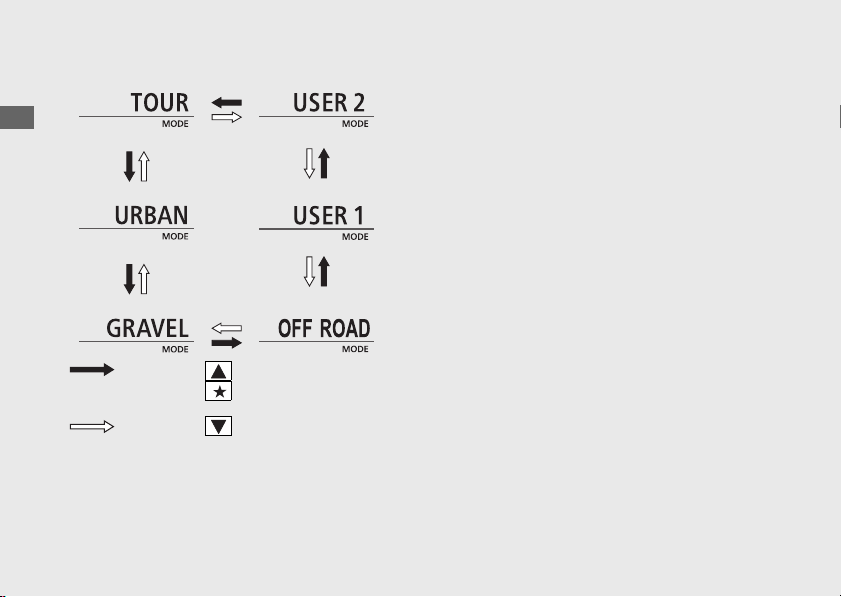
146
Riding mode
(Continued)
Operation Guide
Setting the riding mode
You can change the [P] [Power], [EB] [Engine
Brake], [S] [Overall], [Front], [Rear], ABS mode
[ABS] and [PRELOAD] [Preload] on the [USER 1
MODE] and [USER 2 MODE] of the riding mode.
(P75)
Press the sel up switch or
press the favorite switch
Press the sel down switch

147
Continued
Operation Guide
Audio System
#
About Your Audio System
This audio system can play audio files on
Bluetooth
®
audio devices (mobile phone, digital
audio player or equivalents).
The audio system can pair with
Bluetooth
®
sound devices (speakers, headsets,
communication devices or equivalents).
You can operate the audio system from the
switches on the left handlebar and multi-
information display. However, you cannot
operate some functions by the touch screen
while the vehicle is in motion.
●
Local laws may prohibit the operation of
handheld electronic devices while operating a
vehicle.
●
Only operate audio switches when safe to do
so.
● Set the volume at a level that still allows
horns and emergency vehicles to be heard.
●
Some audio devices, iPhone,
Android
phone
and
Bluetooth
®
sound devices may not be
compatible.
●
We shall not be liable for any damages or
trouble in the use of audio device.
●
iPhone, iPad, iPad Air, iPad Mini, iPod, iPod
touch, iPod classic, iPod shuffle and iPod
nano are trademarks of Apple Inc.
● Google and Android Auto are trademarks
of Google LLC.

148
Audio System
(Continued)
Operation Guide
About Bluetooth
®
audio
● Only one Bluetooth
®
audio device and two
Bluetooth
®
sound devices can be paired
with the audio system at a time. When
another device is paired, the information on
the previously registered device is
cancelled.
● If you receive a call to a paired phone while
playing audio, the paired phone may stop
playing.
● When unable to connect your Bluetooth
®
device to the audio system or when sounds
skip or noises mix while playing, change the
storage location of the Bluetooth
®
device.
Bluetooth
®
Wireless Technology
The Bluetooth
®
word mark and logos are
registered trademarks owned by Bluetooth
SIG, Inc., and any use of such marks by Honda
Motors Co., Ltd., is under license.
Other trademarks and trade names are those
of their respective owners.
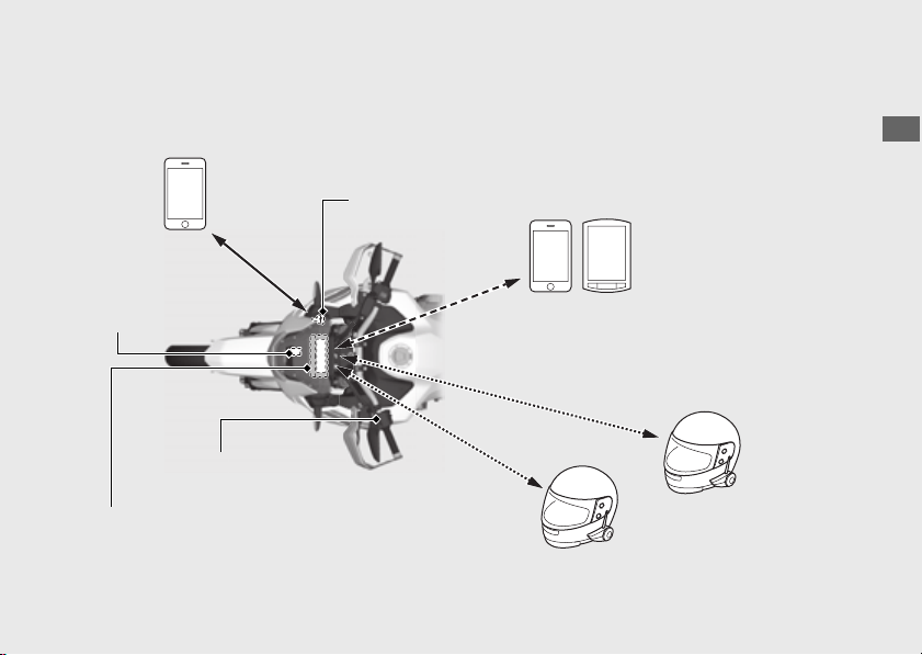
149
Operation Guide
Continued
Audio System Location
iPhone/Android phone
USB connection
(P199)
Multi-information
display
Bluetooth
®
connection (P157)
Left handlebar
switches
Rider Bluetooth
®
headset
Passenger Bluetooth
®
headset
USB connector
iPhone/Android phone/
Mobile phone/Bluetooth
®
audio device, etc.
Bluetooth
®
connection (P162)
Bluetooth
®
connection
(P162)
GPS antenna
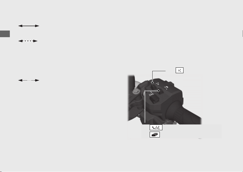
150
Audio System
(Continued)
Operation Guide
#
Basic Operations
You can operate and set the various functions
of the audio system using the touch screen
and/or switches on the left handlebar.
However, you cannot operate some functions
by the touch screen while the vehicle is in
motion.
Audio system supported
profiles:
● HFP ver. 1.5
● A2DP ver. 1.2
● AVRCP ver. 1.4
● PBAP ver. 1.0
● HFP ver. 1.7
● A2DP ver. 1.2
Headset supported
profiles:
USB connection for Apple
CarPlay/Android Auto
[1] Function lever
[8] Voice control switch /
[9] Page switch
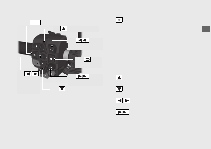
151
Operation Guide
Continued
[1] Function lever: Push forward or pull
backward the lever to adjust the volume.
●
To increase the volume: Push forward the
lever.
●
To decrease the volume: Pull backward the
lever.
●
To increase the volume rapidly: Push forward
and hold the lever.
●
To decrease the volume rapidly: Pull
backward and hold the lever.
[2] Sel up switch: Press the switch to select a
menu item.
[3] Sel down switch: Press the switch to
select a menu item.
[4] Sel left/right switch: Press the switch
to select a menu item.
[5] Skip switch:
●
To skip to the next song: Press the switch.
●
To move rapidly within a track: Press and hold
the switch.
[2] Sel up switch
[3] Sel down switch
[5] Skip
switch
[6] Goes
back switch
[7] switch
ENT
[10] Back
switch
[4]
Sel left/
right
switch
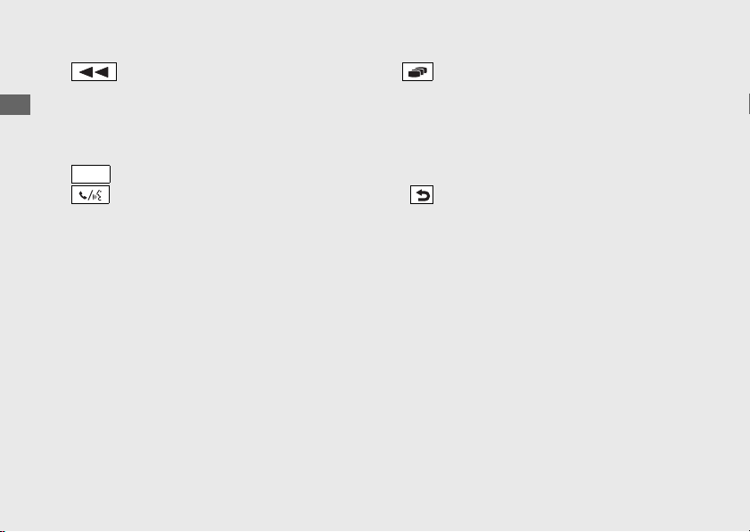
152
Audio System
(Continued)
Operation Guide
[6] Goes back switch:
●
To go back to the beginning of the current or
previous song: Press the switch.
●
To move rapidly within a track: Press and hold
the switch
[7] switch: Press to set your selection.
[8] Voice control switch:
●
To receive or end a call: Push forward the
switch.
●
To reject a call: Push forward and hold the
switch.
●
To start Siri or voice search when Apple
CarPlay or
Android Auto
is available: Push
forward the switch.
[9] Page switch:
●
To return to the riding information or audio
screen: Pull backward the switch.
●
To return to the home screen, Apple CarPlay
screen or voice search screen: Pull backward
and hold the switch.
[10] Back switch:
●
To return to the previous screen: Press the
switch.
●
To return to the audio screen: Press and hold
the switch.
ENT
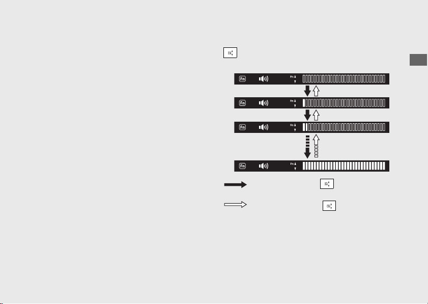
153
Operation Guide
Continued
#
To Adjust the Volume
You can adjust the volume settings for the
headsets.
The system has the following unique volume
levels.
Adjust the volume while in the individual
modes.
● [Music] Rider
● [Music] Passenger
● [Phone]
● [System]
● [Ringtone]
● [Voice]
● [CarPlay]
● [Android Auto]
● [Microphone]
Each volume can also be set from the menu.
(P93)
When you push forward or pull backward the
function lever, the volume control level
appears on the pop-up information.
Push forward the
function lever
Pull backward the
function lever
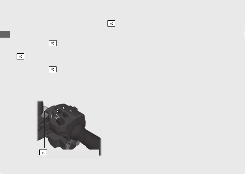
154
Audio System
(Continued)
Operation Guide
To increase the volume: push forward the
function lever.
u
To increase the volume rapidly, push forward
and hold the function lever.
To decrease the volume: pull backward the
function lever.
u
To decrease the volume rapidly, pull backward
and hold the function lever.
Volume level range:
Other than Microphone: Level 0 to 30
Microphone: Level 0 to 14
#
Auto Volume
Selects the volume setting to automatically
increase volume from the headsets as the
speed of the vehicle increases.
To select the Auto Volume:
(P93)
Available settings: [Off]/[Low]/[High]
Default: [Off]
Function lever

155
Operation Guide
Continued
Bluetooth
®
Audio
#
Bluetooth
®
Setting
You can connect with your Bluetooth
®
audio device (mobile phone, digital audio player or
equivalents) and Bluetooth
®
headsets via Bluetooth
®
.
Available devices are as follows:
● [Phone Pairing] (For Bluetooth
®
audio device) (P157)
● [Headset Pairing] (For rider headset and passenger headset) (P162)
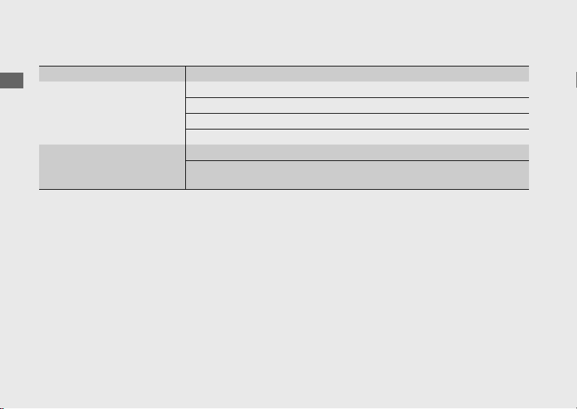
156
Audio System
(Continued)
Operation Guide
Supported Bluetooth
®
version/profiles
● You cannot pair a Bluetooth
®
device and Bluetooth
®
headsets while the vehicle is moving.
When pairing, park your vehicle in a safe place.
● Bluetooth
®
connection cannot be established while launching Apple CarPlay.
● Your vehicle is not equipped with an intercom function. If you want to use the intercom
function, use the intercom function of your headset.
● Some local governments prohibit the use of a headset by the operator of a motor vehicle.
Always obey applicable laws and regulations.
Bluetooth
®
version Bluetooth 2.1 + EDR
Bluetooth
®
profiles (For
iPhone, Android phone,
mobile phone or
Bluetooth
®
device)
HFP (Hand Free Profile) ver. 1.5
A2DP (Advanced Audio Distribution Profile) ver. 1.2
AVRCP (Audio/Video Remote Control Profile) ver. 1.4
PBAP (Phone Book Access Profile) ver. 1.0
Bluetooth
®
profiles (For
rider and passenger
headsets)
HFP (Hand Free Profile) ver. 1.7
A2DP (Advanced Audio Distribution Profile) ver. 1.2
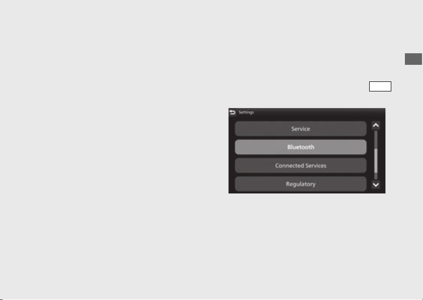
157
Operation Guide
Continued
Phone Pairing
You can establish a Bluetooth
®
connection in
two ways.
● [Discoverable]: Search from the device.
● [Phone Pairing]: Search from the system.
This function is disabled while the vehicle is in
motion.
!a Enable the Bluetooth
®
function on your
device.
u For details, refer to the instruction manual
of your device.
!b Select [Bluetooth], and then press the
switch.
ENT
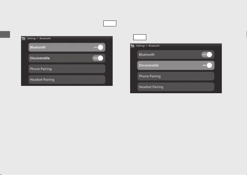
158
Audio System
(Continued)
Operation Guide
!c Select [Bluetooth], and then press the
switch to [ON] (enable) the function.
[Discoverable]
!d Select [Discoverable], and then press the
switch to [ON] (enable) the function.
!e Tap “Honda Motorcycle #*****” on the
Bluetooth
®
setting menu of the target
device.
u The part of ***** is different letter for each
vehicle.
!f When a request message appears on the
target device, tap “Pair.”
ENT
ENT
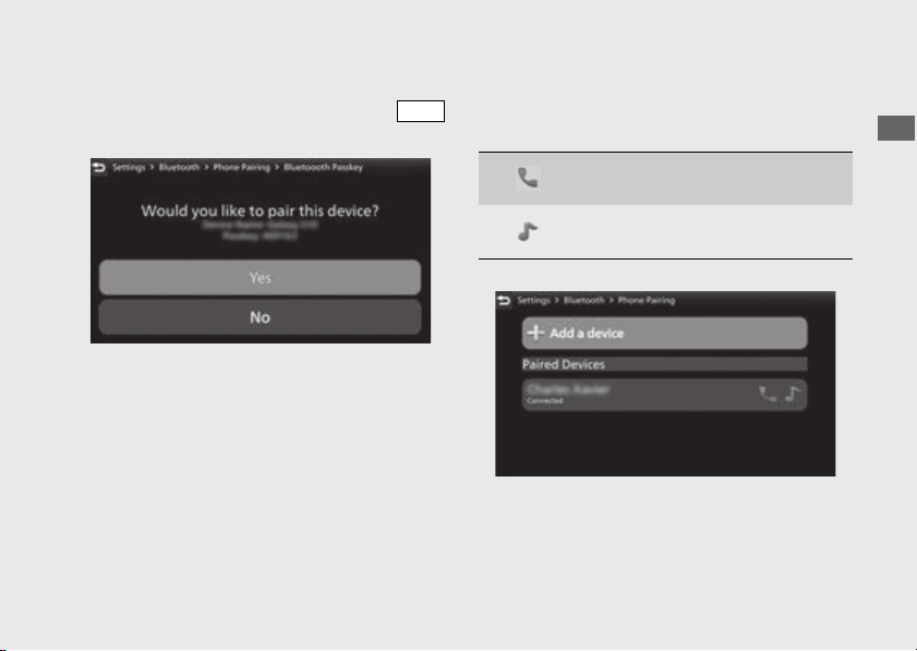
159
Operation Guide
Continued
!g The device name and Passkey appear on the
screen. Select [Yes], and then press the
switch.
!h When the pairing is complete, the name of
the paired device are displayed.
Icon status:
!i Return to the riding information, previous
screen or Home screen.
(P38)
You can also perform the above settings by
using the touch screen.
ENT
: Phone function connected
: Music function connected
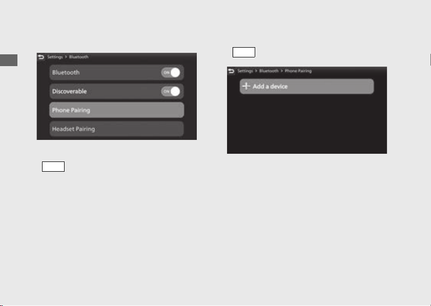
160
Audio System
(Continued)
Operation Guide
[Phone Pairing]
!d Select [Phone Pairing], and then press the
switch.
!e Select [+Add a device], and then press the
switch.
!f The names of the detected device are
displayed.
u If many Bluetooth
®
devices are detected,
the target device may be detected under
the list, scroll down the list.
ENT
ENT
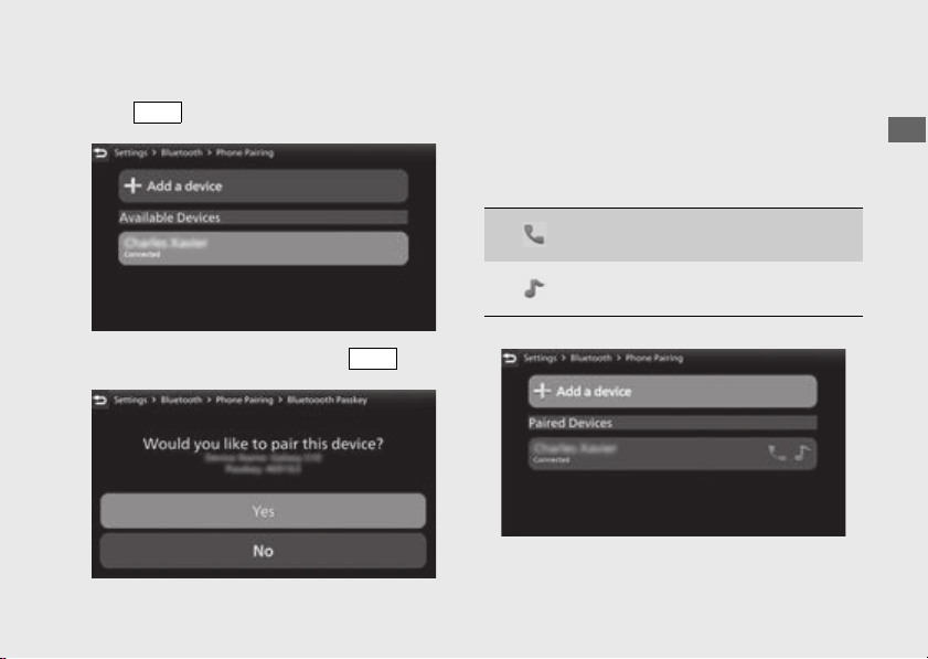
161
Operation Guide
Continued
!g Select a target device name, and then press
the switch.
!h Select [Yes], and then press the switch.
!i When a request message appears on the
target device, tap “Pair.”
!j When the pairing is complete, the name of
the paired device are displayed.
Icon status:
!k Return to the riding information, previous
screen or Home screen.
(P38)
ENT
ENT
: Phone function connected
: Music function connected
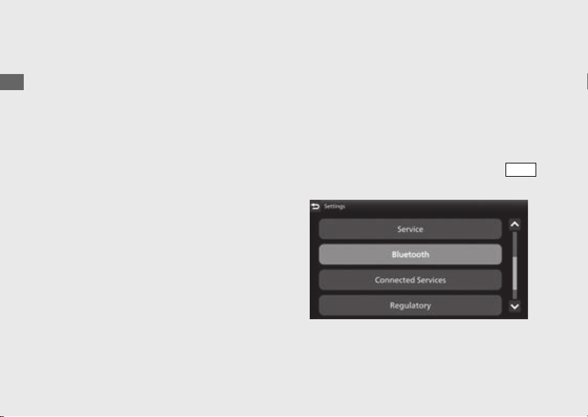
162
Audio System
(Continued)
Operation Guide
You can also perform the above settings by
using the touch screen.
To disconnect the phone:
(P165)
Headset Pairing
This function is disabled while the vehicle is in
motion.
!a Enable the Bluetooth
®
function on your
device.
u For details, refer to the instruction manual
of your device.
!b Select [Bluetooth], and then press the
switch.
ENT
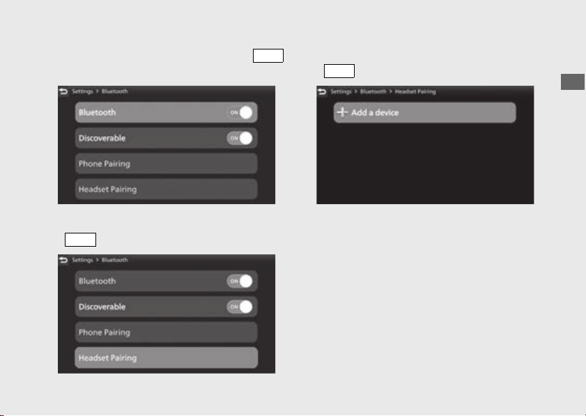
163
Operation Guide
Continued
!c Select [Bluetooth], and then press the
switch to [ON] (enable) the function.
!d Select [Headset Pairing], and then press the
switch.
!e Select [+ Add a device], and then press the
switch.
!f The names of the detected device are
displayed.
u If many Bluetooth
®
devices are detected,
the target device may be detected under
the list, scroll down the list.
ENT
ENT
ENT
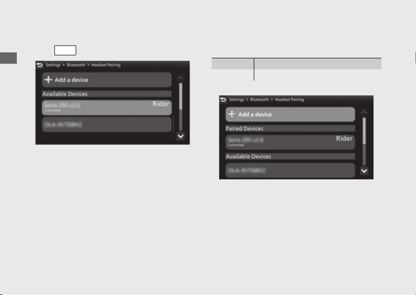
164
Audio System
(Continued)
Operation Guide
!g Select a target device name, and then press
the switch.
!h When the pairing is complete, device name is
displayed.
!i Return to the riding information, previous
screen or Home screen. (P38)
You can also perform the above settings by
using the touch screen.
To disconnect the headset: (P165)
ENT
Rider When pairing rider headset
Passenger When pairing passenger headset
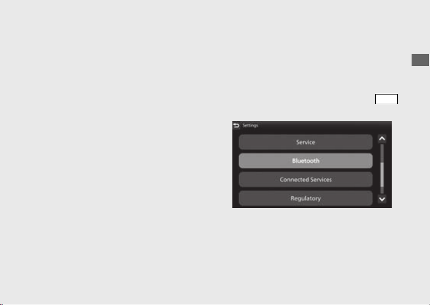
165
Operation Guide
Continued
To Reconnect a Paired Device
Automatically
When the ignition switch is turned ON
position, the system reconnects with
registered devices automatically.
u If the system finds multiple paired devices, the
system will reconnect with the device that was
connected last.
u After reconnecting, the song that was last
played will be played automatically.
To Connect/Disconnect Available
Functions Individually
Depending on the connected device, this
function may not be able to establish a
connection.
!a Select [Bluetooth], and then press the
switch.
ENT
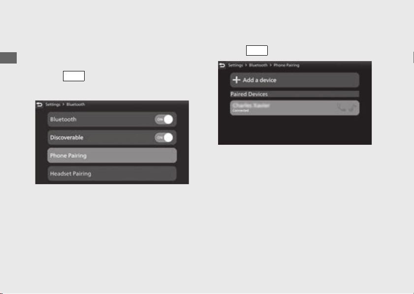
166
Audio System
(Continued)
Operation Guide
To connect functions:
!b [Phone Pairing]
1.
Select [Phone Pairing], and then press
the switch to enter the setting
menu.
2.
Select the paired device, and then press
the switch.
ENT
ENT
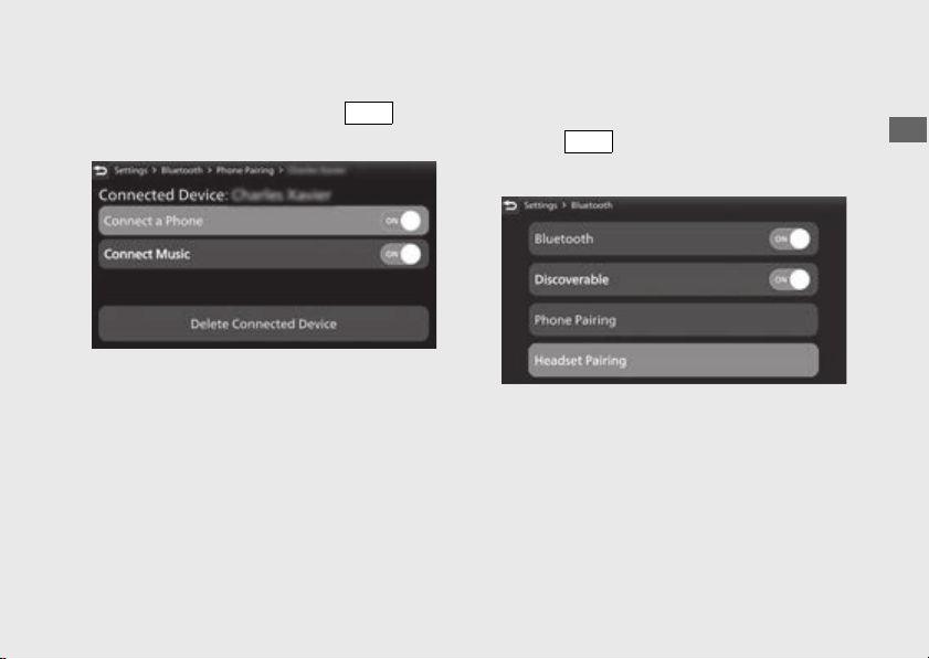
167
Operation Guide
Continued
3.
Select [Connect a Phone] or [Connect
Music], and then press the switch
to [ON] (enable) the function.
!b [Headset Pairing]
1.
Select [Headset Pairing], and then press
the switch to enter the setting
menu.
ENT
ENT
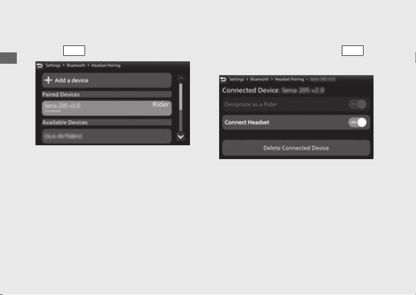
168
Audio System
(Continued)
Operation Guide
2.
Select the paired device, and then press
the switch.
3.
Select [Designate as a Rider] or [Connect
Headset], and then press the
switch to [ON] (enable) the function.
!c Return to the riding information, previous
screen or Home screen.
(P38)
You can also perform the above settings by
using the touch screen.
ENT
ENT
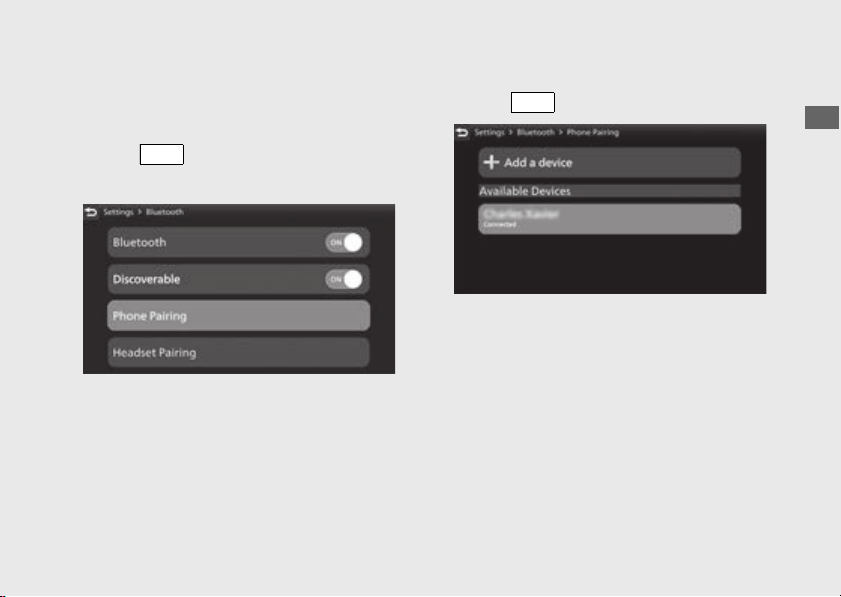
169
Operation Guide
Continued
To disconnect functions:
!b [Phone Pairing]
1.
Select [Phone Pairing], and then press
the switch to enter the setting
menu.
2.
Select the paired device, and then press
the switch.
ENT
ENT
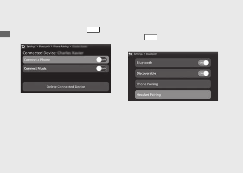
170
Audio System
(Continued)
Operation Guide
3.
Select [Connect a Phone] or [Connect
Music], and then press the switch
to [OFF] (disable) the function.
!b [Headset Pairing]
1.
Select [Headset Pairing], and then press
the switch to enter the setting
menu.
ENT
ENT
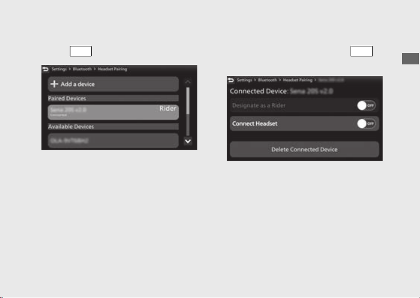
171
Operation Guide
Continued
2.
Select the paired device, and then press
the switch.
3.
Select [Designate as a Rider] or [Connect
Headset], and then press the
switch to [OFF] (disable) the function.
!c Return to the riding information, previous
screen or Home screen.
(P38)
You can also perform the above settings by
using the touch screen.
ENT
ENT
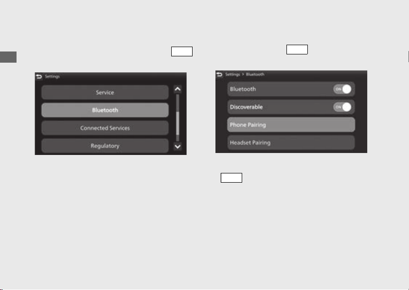
172
Audio System
(Continued)
Operation Guide
To Delete Connected Device
!a Select [Bluetooth], and then press the
switch.
!b Select [Phone Pairing] or [Headset Pairing],
and then press the switch to enter the
setting menu.
!c Select the paired device, and then press the
switch.
ENT
ENT
ENT
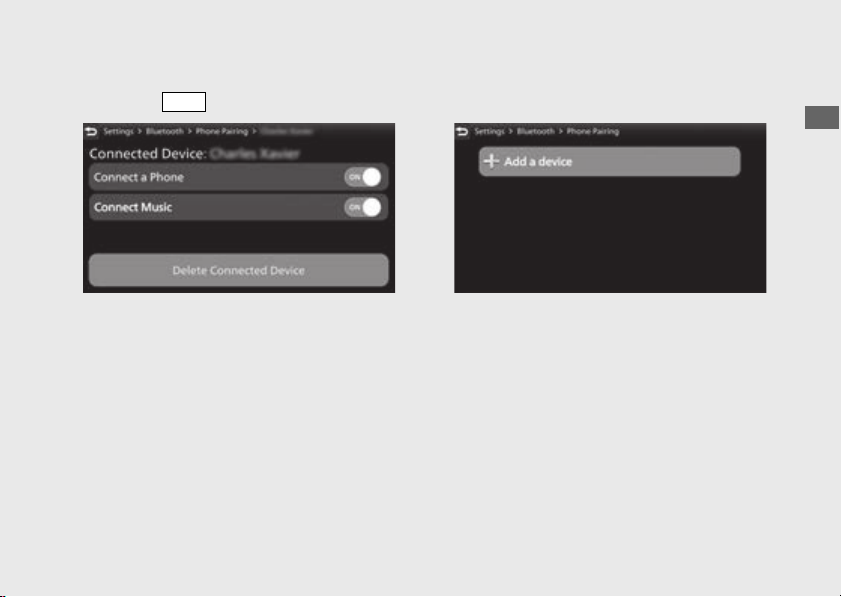
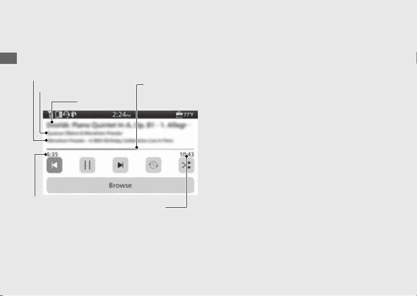
174
Audio System
(Continued)
Operation Guide
Playing Audio
The audio system can play music stored on a
device connected via Bluetooth
®
.
Screen Information
The information displayed on the screen
differs depending on the connected device
and the type of file being played back.
The system supports ID3 tag information. If a
track does not have an ID3 tag, the song title
or file name is displayed.
[1] Song title
[2] Artist name
[3] Album title (Folder name)
[4] Play time
[5] Progress bar
[6] Total time
[3] Album title
[4] Play time
[2] Artist name
[5] Progress
bar
[6] Total time
[1] Song title
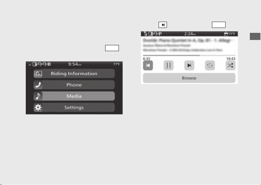
175
Operation Guide
Continued
#
To Play a Track
!a Connect the device you want to play from.
Bluetooth
®
setting: (P165)
!b Select [Media], and then press the
switch.
!c Select , and then press the switch.
!d Return to the riding information, previous
screen or Home screen.
(P38)
You can also perform the above settings by
using the touch screen.
ENT
ENT
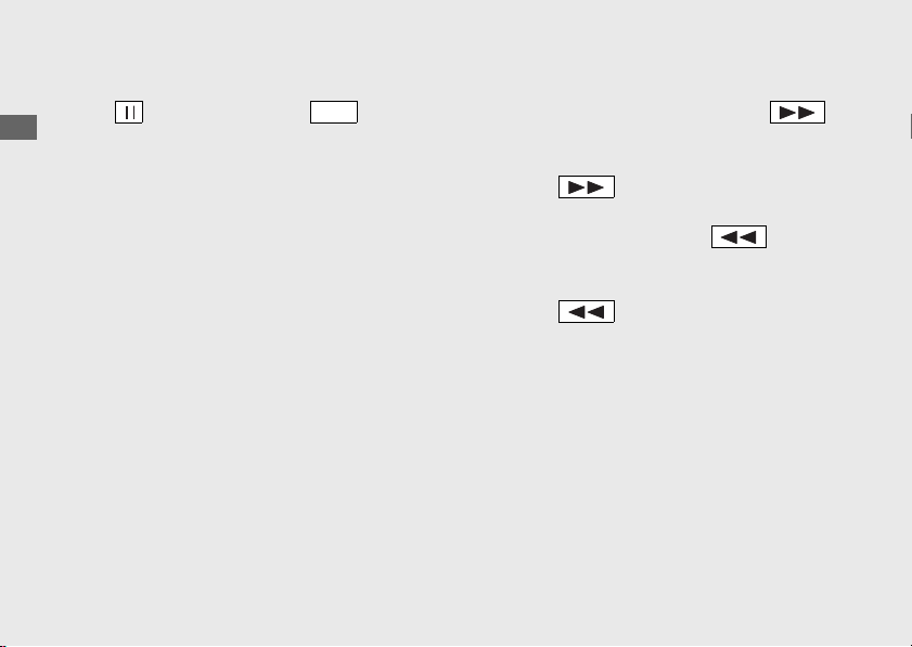
176
Audio System
(Continued)
Operation Guide
#
To Pause a Track
Select , and then press the switch.
You can also perform the above settings by
using the touch screen.
#
To Change a Track
● To skip to the next song: Press the
skip switch.
● To move rapidly within a track: Press and
hold the skip switch.
● To go back to the beginning of the current
or previous song: Press the goes
back switch.
● To move rapidly within a track: Press and
hold the goes back switch.
You can also perform the above settings by
using the touch screen.
ENT
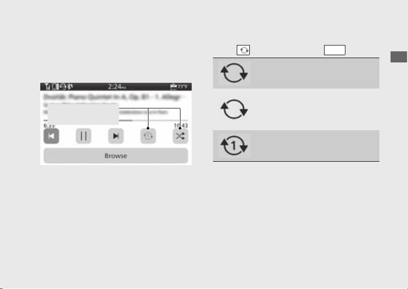
177
Operation Guide
Continued
#
To Select the Play Mode
You can select repeat and random modes.
The audio play mode status icon or color of
the audio play mode status icon changes.
Cycles through the play modes as follows:
Select , and then press the switch.
Audio play mode
status icons
(Black) No repeat mode: No
repeat.
(Blue) Album repeat play mode:
Repeats all tracks in the current
playlist ([Artists], [Albums] or
[Songs], etc.).
(Blue) Track repeat play mode:
Repeats the current track.
ENT
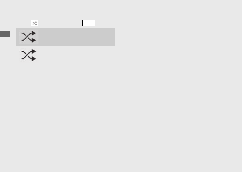
178
Audio System
(Continued)
Operation Guide
Select , and then press the switch.
You can also perform the above settings by
using the touch screen.
(Black) Normal play mode: Plays
tracks in original order.
(Blue) Random play mode: Plays
tracks randomly.
ENT

179
Operation Guide
Continued
Handsfree Calling
Using Bluetooth
®
Handsfree Calling
Bluetooth
®
handsfree calling allows you to
make and receive phone calls using your
vehicle's audio system, without handling your
mobile phone.
To use the handsfree calling, you need a
Bluetooth
®
compatible mobile phone and
Bluetooth
®
headsets.
● You cannot operate the handsfree calling
functions by the touch screen while the
vehicle is in motion.
● If Bluetooth
®
connection is unstable due to
surrounding conditions or radio wave
conditions, the handsfree calling functions
may not be available.
●
While talking, you may be hard to hear due
to wind noise during running or external
noise. In that case, try to change the
position of the microphone.
While talking, you may be hard to hear due
to wind noise during running or external
noise. In that case, try to change the
position of the microphone or to adjust the
windscreen height.
(P305)
CRF1100A/D
CRF1100A4/D4
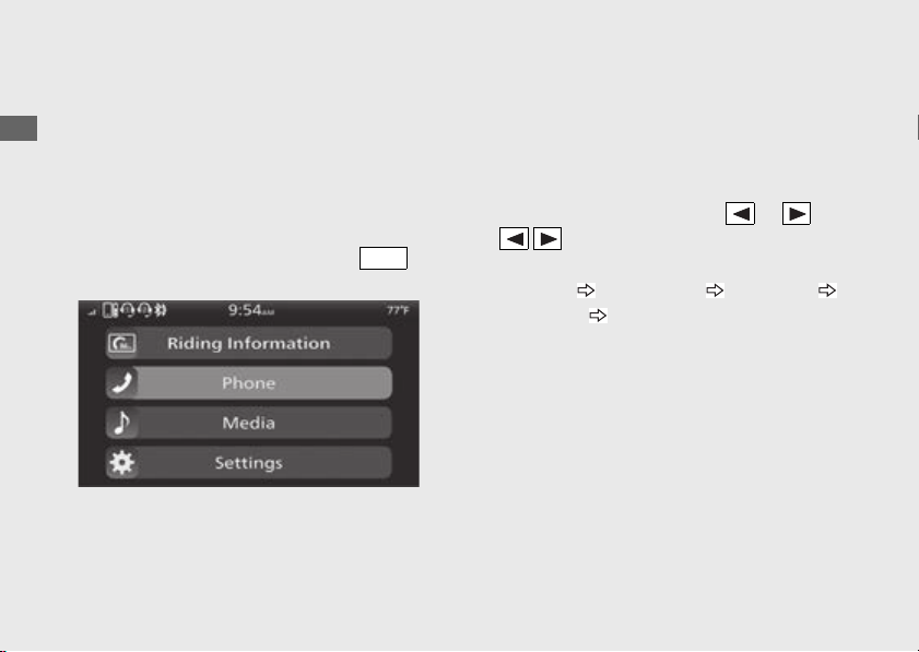
180
Audio System
(Continued)
Operation Guide
#
Preparation
!a Connect with the paired mobile phone.
(P157)
u The phonebook is updated after every
connection. Call history is updated after
every connection or call.
!b Connect the paired rider headset.
(P162)
!c Select [Phone], and then press the
switch.
!d Return to the riding information, previous
screen or Home screen.
(P38)
You can also perform the above settings by
using the touch screen.
#
Making a Call
You can make calls by inputting a phone
number or by using the phonebook, call
history or speed dial entries.
To change the call mode, push or on
the sel left/right switch.
Changes the call modes as follows:
[Call History] [Speed Dial] [Contacts]
[Dial Number] [Settings]
● Certain manual functions are disabled while
the vehicle is in motion. You cannot select a
greyed-out option until the vehicle is
stopped.
● Only previously stored speed dial entries
and call history can be called while the
vehicle is in motion.
To adjust the phone volume:
(P93)
ENT
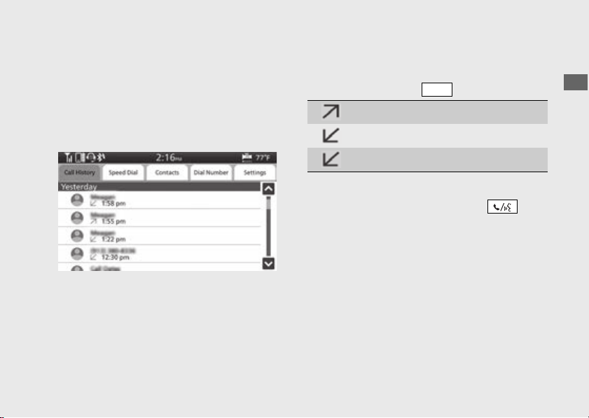
181
Operation Guide
Continued
To Make a Call Using the Call History
[Call History]
You can make a call using the call history while
the vehicle is in motion.
Call history displays the last 30 dialed,
received, or missed calls.
!a Select [Call History].
!b Select the phone number you want to call,
and then press the switch.
!c To end the call, push forward the voice
control switch on the left handlebar.
u The same action can be done by selecting
[End Call] on the screen.
!d Return to the riding information, previous
screen or Home screen.
(P38)
You can also perform the above settings by
using the touch screen.
(blue): Dialed call
(blue): Received call
(red): Missed call
ENT
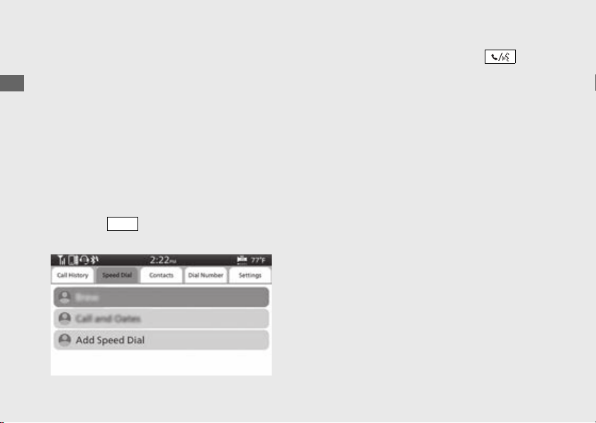
182
Audio System
(Continued)
Operation Guide
To Make a Call Using a Speed Dial Entry
[Speed Dial]
You can make a call using the speed dial while
the vehicle is in motion.
To make a call using the speed dial, you need
to store the speed dial number in advance.
(P185)
Up to 20 speed dial numbers can be stored.
!a Select [Speed Dial].
!b Select a person you want to call, and then
press the switch.
Dialing starts automatically.
!c To end the call, push forward the voice
control switch on the left handlebar.
u The same action can be done by selecting
[End Call] on the screen.
!d Return to the riding information, previous
screen or Home screen.
(P38)
You can also perform the above settings by
using the touch screen.
ENT
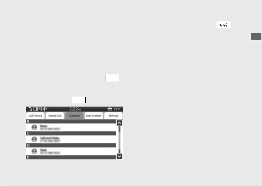
183
Operation Guide
Continued
To Make a Call Using the Phonebook
[Contacts]
This function is disabled while the vehicle is in
motion.
!a Stop the vehicle.
!b Select [Contacts].
!c The phonebook is stored alphabetically.
Select a name, and then press the
switch to set your selection.
!d Select the phone number you want to call,
and then press the switch.
!e To end the call, push forward the voice
control switch on the left handlebar.
u The same action can be done by selecting
[End Call] on the screen.
!f Return to the riding information, previous
screen or Home screen.
(P38)
You can also perform the above settings by
using the touch screen.
ENT
ENT
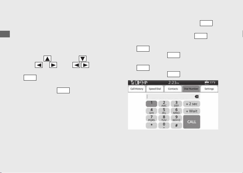
184
Audio System
(Continued)
Operation Guide
To Make a Call Using a Phone Number
[Dial Number]
This function is disabled while the vehicle is in
motion.
!a Select [Dial Number].
!b Press the sel switch or sel switch or
push or on the sel left/right
switch to enter a number, and then press the
switch to set the number.
u When using [+]: Select [0], and then press
and hold the switch.
!c Select [CALL], and then press the
switch to make a call.
u To cancel the call, press the switch.
u When making a call 1 second after the
switch pressed: Select [+ Wait], and
then press the switch.
u When making a call 2 seconds after the
switch pressed: Select [+ 2 sec], and
then press the switch.
ENT
ENT
ENT
ENT
ENT
ENT
ENT
ENT
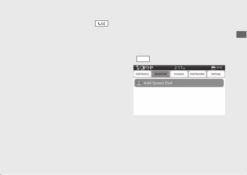
185
Operation Guide
Continued
!d To end the call, push forward the voice
control switch on the left handlebar.
u The same action can be done by selecting
[End Call] on the screen.
!e Return to the riding information, previous
screen or Home screen.
(P38)
You can also perform the above settings by
using the touch screen.
To Store a Phone Number in the Speed
Dial List
Speed dial numbers can be stored.
!a Select [Speed Dial].
!b Select [Add Speed Dial], and then press the
switch.
!c The phonebook appears.
ENT
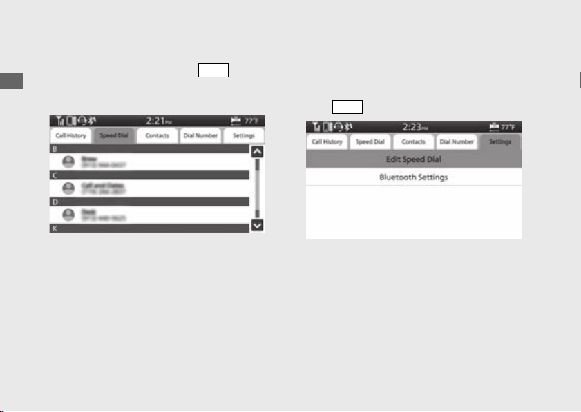
186
Audio System
(Continued)
Operation Guide
!d Select the phone number you want to store,
and then press and hold the switch.
The phone number will be stored in the
speed dial list.
!e Return to the riding information, previous
screen or Home screen.
(P38)
You can also perform the above settings by
using the touch screen.
To Delete a Stored Speed Dial Number
!a Select [Settings].
!b Select the [Edit Speed Dial], and then press
the switch.
ENT
ENT
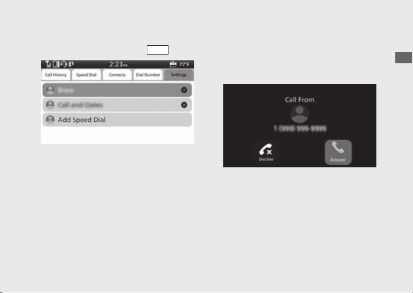
187
Operation Guide
Continued
!c Select the phone number you want to delete,
and then press and hold the switch.
!d Return to the riding information, previous
screen or Home screen.
(P38)
You can also perform the above settings by
using the touch screen.
#
Receiving a Call
When there is an incoming call, an audible
notification sounds and the Incoming Call
screen appears.
ENT

188
Audio System
(Continued)
Operation Guide
Ring Tone
If the connected mobile phone supports “in
band ring tone”, the ring tone stored on the
phone sounds automatically while receiving a
call.
If “in band ring tone” is not supported, the ring
tone stored in the audio system sounds.
To Receive a Call
When a call comes in, push forward the
voice control switch on the left handlebar to
receive the call.
● The same action can be done by selecting
[Answer] on the screen.
To adjust the phone volume:
(P93)
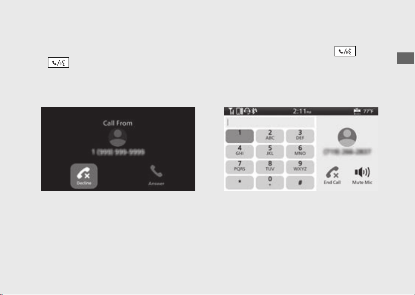
189
Operation Guide
Continued
To Decline a Call
When a call comes in, push forward and hold
the voice control switch on the left
handlebar to reject a call.
● The same action can be done by selecting
[Decline] on the screen.
To End a Call
While talking, push forward the voice
control switch on the left handlebar to end the
call.
● The same action can be done by selecting
[End Call] on the screen.

190
Audio System
(Continued)
Operation Guide
Apple CarPlay
If you connect an Apple CarPlay-compatible
iPhone to the system via USB, you can use the
multi-information display, instead of the iPhone
display, to make phone calls, listen to music, view
maps (navigation), and access messages.
●
Only iPhone 5 or newer versions with iOS 10
or later are compatible with Apple CarPlay.
●
Park your vehicle in a safe place before
connecting your iPhone to Apple CarPlay and
when launching any compatible apps.
●
In no event shall Honda be liable for any
damage or trouble that occurs in the use of
iPhone.
●
If a mobile network communication is
unstable due to surrounding conditions or
signal strength conditions, Apple CarPlay
functions may not be available.
●
To use Apple CarPlay, a headset connection is
necessary. If headset connection is broken
due to headset battery depletion or
communication failure, Apple CarPlay cannot
be used until the connection is restored.
●
You cannot operate Apple CarPlay by the
touch screen while the vehicle is in motion.

191
Operation Guide
Continued
●
Application and menu items displayed on the
screen may differ depending on the
connected device and iOS version.
●
While connected to Apple CarPlay, calls are
only made through Apple CarPlay. If you want
to make a call with
Bluetooth
®
handsfree
calling, disconnect the USB cable from your
iPhone and connect your iPhone via
Bluetooth
®
.
To connect the paired device: (P157)
●
For details on countries and regions where
Apple CarPlay is available, as well as
information pertaining to function, refer to
the Apple homepage.
●
Apple CarPlay is a trademark of Apple Inc.

192
Audio System
(Continued)
Operation Guide
#
Apple CarPlay Operating Requirements
& Limitations
Apple CarPlay requires a compatible iPhone
with an active cellular connection and data
plan. Your carrier’s rate plans will apply.
Changes in operating systems, hardware,
software, and other technology integral to
providing Apple CarPlay functionality, as well
as new or revised governmental regulations,
may result in a decrease or cessation of Apple
CarPlay functionality and services.
Honda cannot and does not provide any
warranty or guarantee of future Apple CarPlay
performance or functionality.
It is possible to use 3rd party apps if they are
compatible with Apple CarPlay. Refer to the
Apple homepage for information on
compatible apps.
#
Use of User and Vehicle Information
The use and handling of user and vehicle
information transmitted to/from your iPhone
by Apple CarPlay is governed by the Apple
iOS terms and conditions and Apple’s Privacy
Policy.
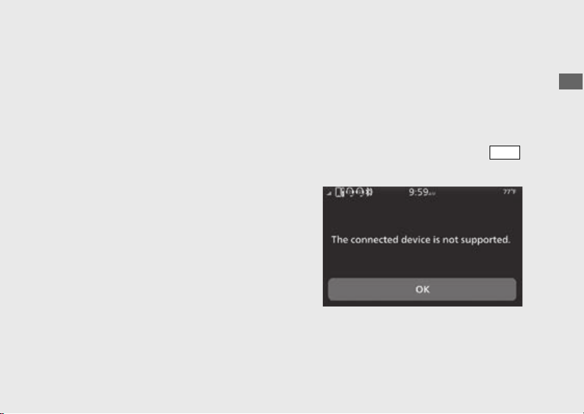
193
Operation Guide
Continued
#
To Setup Apple CarPlay
Use of Apple CarPlay will result in the
transmission of certain user and vehicle
information (such as vehicle location, speed,
and status) to your iPhone to enhance the
Apple CarPlay experience. You will need to
consent to the sharing of this information on
the screen.
!a Pair the headsets. (P162)
!b Connect your iPhone using a certified cable
to the USB socket. (P199)
u If the following screen is displayed, Apple
CarPlay can not be used, but USB power
can be supplied.
1.
Select [OK], and then press the
switch.
To enable Apple CarPlay: (P195)
ENT
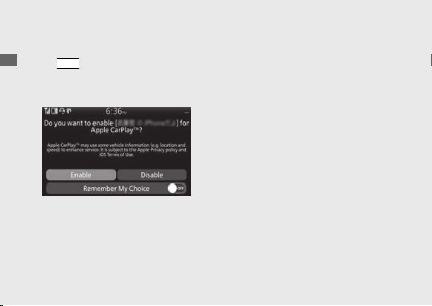
194
Audio System
(Continued)
Operation Guide
!c When the disclaimer message appears on
the screen, select [Enable], and then press
the switch.
u Set [Remember My Choice] to ON so that
you will not be asked the next time you
connect.
[Enable] when [Remember My Choice]
is [OFF]: Allows only once. (Prompt shows
again next time.)
[Enable] when [Remember My Choice]
is [ON]: Allows anytime. (Prompt does not
show again.)
[Disable] when [Remember My Choice]
is [OFF]: Does not allow this consent.
[Disable] when [Remember My Choice]
is [ON]: Does not allow anytime. (Prompt
does not show again.)
!d Enable the Apple CarPlay setting.
(P195)
!e Apple CarPlay menu screen appears.
You can also perform the above settings by
using the touch screen.
To display the prompt: (P197)
ENT
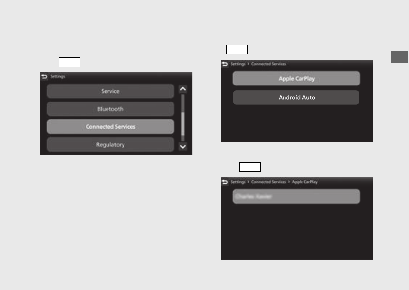
195
Operation Guide
Continued
To Enable or Disable Apple CarPlay
!a Select [Connected Services], and then press
the switch.
!b Select [Apple CarPlay], and then press the
switch.
!c Select a target device name, and then press
the switch.
ENT
ENT
ENT

196
Audio System
(Continued)
Operation Guide
To enable Apple CarPlay:
!d Select [Enable Apple CarPlay], and then press
the switch to [ON] (enable) the
function.
!e Return to the riding information, previous
screen or Home screen.
(P38)
You can also perform the above settings by
using the touch screen.
To disable Apple CarPlay:
!d Select [Enable Apple CarPlay], and then press
the switch to [OFF] (disable) the
function.
!e Return to the riding information, previous
screen or Home screen.
(P38)
You can also perform the above settings by
using the touch screen.
ENT
ENT
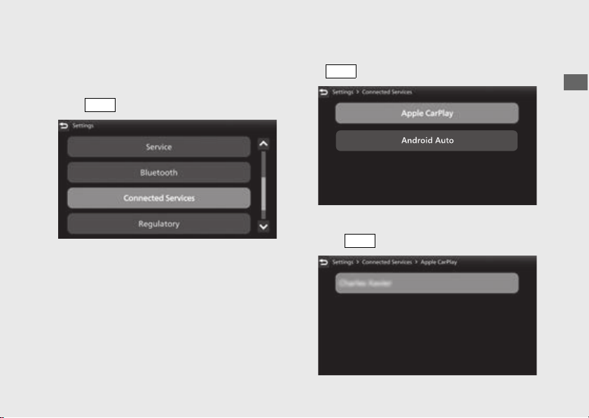
197
Operation Guide
Continued
To Select Ask On or Ask Off of the Apple
CarPlay disclaimer Screen
!a Select [Connected Services], and then press
the switch.
!b Select [Apple CarPlay], and then press the
switch.
!c Select a target device name, and then press
the switch.
ENT
ENT
ENT
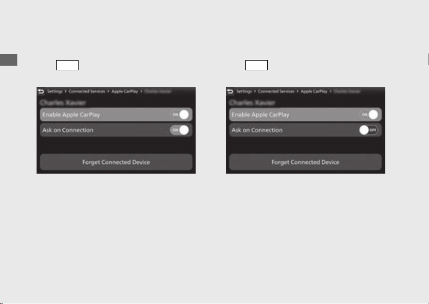
198
Audio System
(Continued)
Operation Guide
To ask on connection:
!d Select [Ask on Connection], and then press
the switch to [ON] (ask on) the
function.
!e Return to the riding information, previous
screen or Home screen.
(P38)
You can also perform the above settings by
using the touch screen.
To ask off connection:
!d Select [Ask on Connection], and then press
the switch to [OFF] (ask off) the
function.
!e Return to the riding information, previous
screen or Home screen.
(P38)
You can also perform the above settings by
using the touch screen.
ENT
ENT

199
Operation Guide
Continued
#
To Connect Your iPhone
●
Do not leave your device in the vehicle (under
the front seat or under the rear seat etc.).
High heat will damage it.
●
We recommend backing up your data before
playing it.
●
iPhone can be charged with the USB cable
when the ignition switch is in the ON position.
The charging time may be longer than usual.
●
We recommend covering your devices with
an audio pouch, or soft fabric or cover to
protect them from damage.
●
Be careful to not get the USB connector wet.
●
Do not connect with a hub.
●
Do not connect incompatible devices.
●
If the audio system does not recognise the
iPhone, try reconnecting it a few times or
reboot the device.
To connect your iPhone: (P238)
#
To Disconnect Your iPhone
You can disconnect your iPhone at any time.
Make sure to follow the device’s instructions
on how to disconnect the device from the
cable.
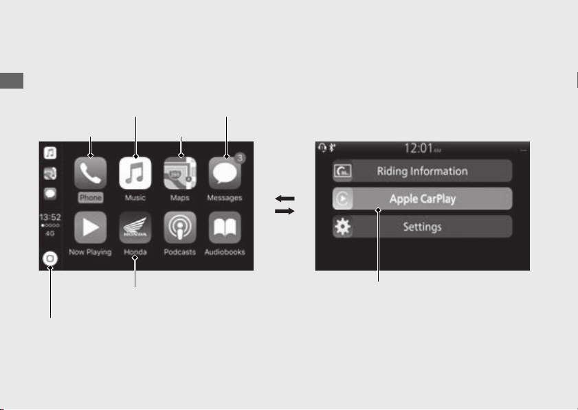
200
Audio System
(Continued)
Operation Guide
#
Apple CarPlay Menu
Apple CarPlay menu screen
Maps
Go back to Apple CarPlay
menu screen
Go back to Home screen
Messages
Music
Phone
Home screen
Go to Apple CarPlay
menu screen

201
Operation Guide
Continued
Phone
Access the contact list, make phone calls, or listen to voice mail.
Music
Play music stored on your iPhone.
Maps
Display Apple CarPlay map and use the navigation function just as you would on your iPhone.
Messages
Check and reply to text messages, or have messages read to you.
Honda
Go back to the Home screen.
Go back to the Apple CarPlay menu screen.

202
Audio System
(Continued)
Operation Guide
#
Operating Apple CarPlay with Siri
To activate Siri, pairing with device such as a
headset (for rider) must be paired.
(P162)
To Activate Siri
!a Start Apple CarPlay. (P193)
!b Unlock your iPhone and enable Siri.
u For details, refer to the iPhone User Guide,
etc.
!c Push forward the voice control switch
on the left handlebar.
!d Say a voice command through the paired
headset.
Siri may not be recognised correctly due to
the effect of wind noise during running or
external noise. In that case, try to change the
position of the microphone.
Siri may not be recognised correctly due to
the effect of wind noise during running or
external noise. In that case, try to change the
position of the microphone or to adjust the
windscreen height.
(P305)
CRF1100A/D
CRF1100A4/D4

203
Operation Guide
Continued
Please visit www.apple.com/ios/siri.
To Deactivate Siri
!a Push forward the voice control switch
on the left handlebar.
You can also perform the above settings by
using the touch screen.
Siri is a trademark of Apple Inc.

204
Audio System
(Continued)
Operation Guide
Android Auto
If you connect an Android Auto compatible
Android™ phone to the system via USB port,
you can use the multi-information display,
instead of the Android phone display to
access the Phone, Google Maps™
(Navigation), Notification center, and voice
search functions.
When you first use Android Auto, you will be
required to complete initial setting on your
phone screen. We recommend that you
complete this initial setting while safely parked
before using Android Auto.
● To use Android Auto, you need to
download the Android Auto app from
Google Play™ to your smartphone.
● Only Android 5.0 or later versions are
compatible with Android Auto. Bluetooth
A2DP cannot be used with Android phone.
● Park your vehicle in a safe place before
connecting your Android phone to Android
Auto and when launching any compatible
apps.
● In no event shall Honda be liable for any
damages or troubles that occur in the use
of Android phone.
● If a mobile network communication is
unstable due to surrounding conditions or
signal strength conditions, Android Auto
functions may not be available.
● To use full functions of Android Auto, a
headset connection is necessary.
To connect the paired device:
(P157)
● You cannot operate Android Auto by the
touch screen while the vehicle is in motion.
● Application and menu items displayed on
the screen may differ depending on the
connected device and Android version.

205
Operation Guide
Continued
● When your Android phone is connected to
Android Auto, it is not possible to use the
Bluetoothr Audio.
● You can connect your Android phone using
a certified cable to the USB connector
directly. Make sure to use the factory USB
cable that came with your device.
● The audio system may not be compatible
with the latest model and the latest OS
version.
● For details on countries and regions where
Android Auto is available, as well as
information pertaining to function, refer to
the Android Auto homepage.
● Google, Android, Google Maps, Google
Play and Android Auto are trademarks of
Google LLC.
#
Android Auto Operating Requirements
& Limitations
Android Auto requires a compatible Android
phone with an active cellular connection and
data plan. Your carrier’s rate plans will apply.
Changes in operating systems, hardware,
software, and other technology integral to
providing Android Auto functionality, as well
as new or revised governmental regulations,
may result in a decrease or cessation of
Android Auto functionality and services.
Honda cannot and does not provide any
warranty or guarantee of future Android Auto
performance or functionality.
It is possible to use 3rd party apps if they are
compatible with Android Auto. Refer to the
Android Auto homepage for information on
compatible apps.

206
Audio System
(Continued)
Operation Guide
#
Use of User and Vehicle Information
The use and handling of user and vehicle
information transmitted to /from your phone
by Android Auto is governed by the Google’s
Privacy Policy.

207
Operation Guide
Continued
#
To Setup Android Auto
When you connect an Android phone to the
unit via the USB port, Android Auto is
automatically initiated.
Use of Android Auto will result in the
transmission of certain user and vehicle
information (such as vehicle location, speed,
and status) to your Android phone to enhance
the Android Auto experience. You will need to
consent to the sharing of this information on
the screen.
!a Pair the headsets. (P162)
!b Connect your Android phone to the USB
socket. (P238)
u Only initialize Android Auto when you
safely parked. When Android Auto first
detects your phone, you will need to set
up your phone so that auto pairing is
possible.
Refer to the instruction manual that came
with your phone.
!c When the disclaimer message appears on
the screen, select [Enable] and then
switch.
u Set [Remember My Choice] to ON so that
you will not be asked the next time you
connect.
ENT
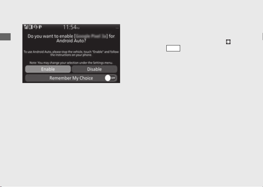
208
Audio System
(Continued)
Operation Guide
[Enable] when [Remember My Choice]
is [OFF]: Allows only once. (Prompt shows
again next time.)
[Enable] when [Remember My Choice]
is [ON]: Allows anytime. (Prompt does not
show again.)
[Disable] when [Remember My Choice]
is [OFF]: Does not allow this consent.
[Disable] when [Remember My Choice]
is [ON]: Does not allow anytime. (Prompt
does not show again.)
!d Enable the Android Auto setting
(P213)
!e Android Auto screen appears.
!f To appear App launcher screen, select and
then press switch.
You can also perform the above settings by
using the touch screen.
To display the prompt:
(P215)
ENT
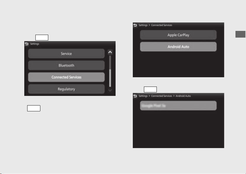
209
Operation Guide
Continued
To Enable or Disable Android Auto
!a Select [Connected Services], and then press
the switch.
!b Select [Android Auto], and then press the
switch.
!c Select a target device name, and then press
the switch.
ENT
ENT
ENT
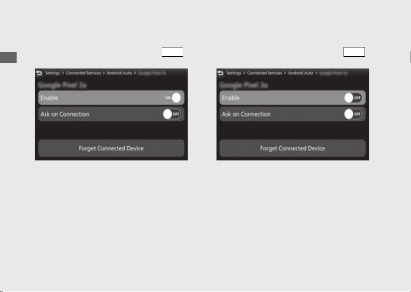
210
Audio System
(Continued)
Operation Guide
To enable Android Auto:
!d Select [Enable], and then press the
switch to [ON] (enable) the function.
!e Return to the riding information, previous
screen or Home screen.
(P38)
You can also perform the above settings by
using the touch screen.
To disable Android Auto:
!d Select [Enable], and then press the
switch to [OFF] (disable) the function.
!e Return to the riding information, previous
screen or Home screen.
(P38)
You can also perform the above settings by
using the touch screen.
ENT
ENT
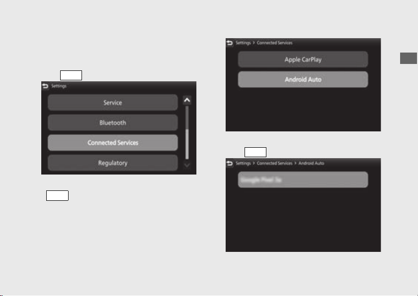
211
Operation Guide
Continued
To Select Ask On or Ask Off of the
Android Auto disclaimer Screen
!a Select [Connected Services], and then press
the switch.
!b Select [Android Auto], and then press the
switch.
!c Select a target device name, and then press
the switch.
ENT
ENT
ENT
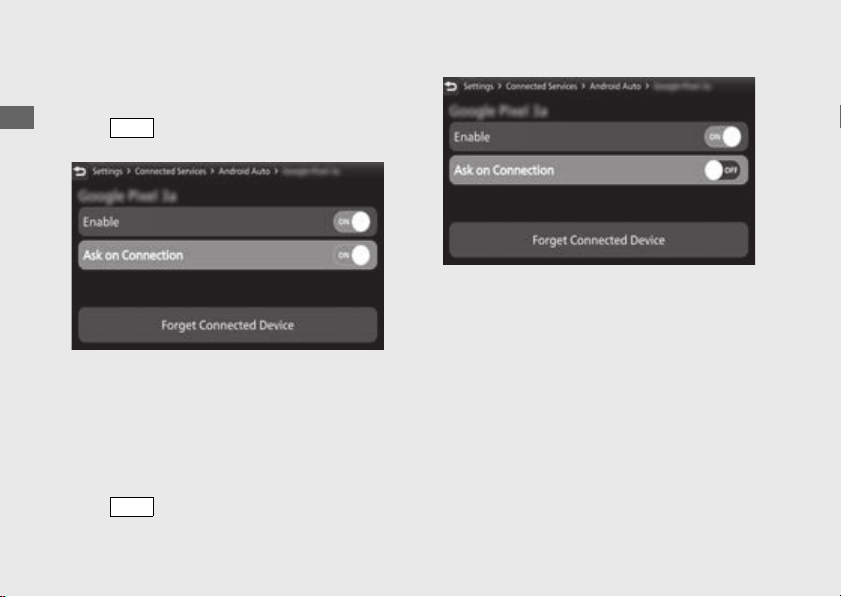
212
Audio System
(Continued)
Operation Guide
To ask on connection:
!d Select [Ask on Connection], and then press
the switch to [ON] (ask on) the
function.
!e Return to the riding information, previous
screen or Home screen.
(P38)
You can also perform the above settings by
using the touch screen.
To ask off connection:
!d Select [Ask on Connection], and then press
the switch to [OFF] (ask off) the
function.
!e Return to the riding information, previous
screen or Home screen.
(P38)
You can also perform the above settings by
using the touch screen.
ENT
ENT

213
Operation Guide
Continued
#
To Connect Your Android phone
● Do not leave your device in the vehicle
(under the front seat or under the rear seat
etc.). High heat will damage it.
● We recommend backing up your data
before playing it.
● Android phone can be charged with the
USB cable when the ignition switch is in the
(On) position. The charging time may be
longer than usual.
● We recommend covering your devices with
an audio pouch, or soft fabric or cover to
protect them from damage.
● Be careful to not get the USB connector
wet.
● Do not connect with a hub.
● If the audio system does not recognize the
Android phone, try reconnecting it a few
times or reboot the device.
To connect your Android phone:
(P238)
#
To Disconnect Your Android phone
You can disconnect your Android phone at at
any time.
Make sure to follow the device’s instructions
on how to disconnect the device from the
cable.
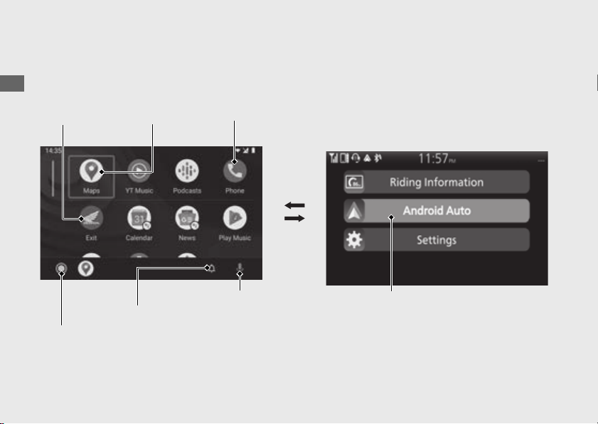
214
Audio System
(Continued)
Operation Guide
#
App launcher screen
Go to App
launcher screen
Notification
center
Phone
Maps
Home screen
Go to Android Auto
screen
Voice
search
Exit
App launcher screen

215
Operation Guide
Continued
Maps
Display Google Maps and use the navigation function just as you would with your Android
phone. When the vehicle is in motion, it is not possible to make keyboard entries. Stop the
vehicle in a safe location to undertake a search or provide other inputs.
Phone
Make and receive phone calls as well as listen to voicemail.
Voice search
Operate Voice search.
Notification center
See recent calls, messages, and alerts.
Go to App launcher screen
The app launcher opens.
Exit
Go back to the Home Screen.
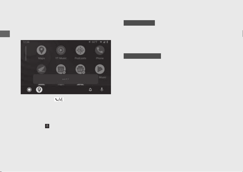
216
Audio System
(Continued)
Operation Guide
#
Operating voice search
To activate the voice search, a device such as
a headset must be paired.
(P162)
Push forward the voice control switch on
the left handlebar to operate Android Auto
with your voice.
You can also activate the voice search by
selecting the icon.
Voice search may not be recognized correctly
due to the effect of wind noise during running
or external noise. In that case, try to change
the position of the microphone.
Voice search may not be recognized correctly
due to the effect of wind noise during running
or external noise. In that case, try to change
the position of the microphone or adjust the
windscreen height.
(P305)
CRF1100A/D
CRF1100A4/D4

217
Operation Guide
Below are examples of commands you
can give with voice recognition :
● Reply to text.
● Call my wife.
● Navigate to Honda.
● Play my music.
● Send a text message to my wife.
● Call flower shop.
For more information, please refer to the
Android Auto homepage.
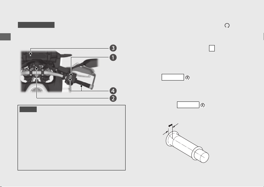
218
Operation Guide
Starting the Engine
Start your engine using the following procedure,
regardless of whether the engine is cold or warm.
!a
Make sure the engine stop switch is in the (Run)
position.
!b
Turn the ignition switch to the ON position.
!c
Shift the transmission to Neutral ( indicator
come on). Alternatively, pull in the clutch lever to
start your vehicle with the transmission in gear so
long as the side stand is raised.
!d
Press the button with the throttle
completely closed.
u
If you cannot start the engine, open the throttle
slightly (about 1/8 in (3 mm), without freeplay)
and press the button.
NOTICE
●
If the engine does not start within 5 seconds, turn the
ignition switch to the OFF position and wait 10
seconds before trying to start the engine again to
recover battery voltage.
●
Extended fast idling and revving the engine can damage
the engine and the exhaust system.
●
Snapping the throttle or fast idling for more than about 5
minutes may cause exhaust pipe discoloration.
●
The engine will not start if the throttle is fully open.
CRF1100A/A4
N
START
START
About 1/8 in (3 mm), without freeplay

219
Operation Guide
Continued
If the engine does not start:
!a Open the throttle fully and press the
button for 5 seconds.
!b Repeat the normal starting procedure.
!c If the engine starts, open the throttle slightly
if idling is unstable.
!d If the engine does not start, wait 10 seconds
before trying steps
!a & !b again.
#
If Engine Will Not Start (P308)
START
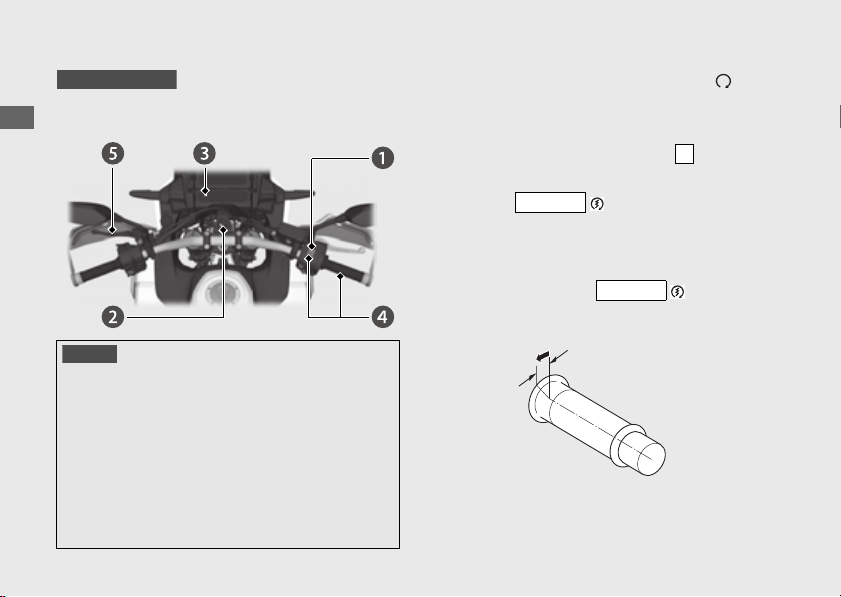
220
Starting the Engine
(Continued)
Operation Guide
Start your engine using the following procedure,
regardless of whether the engine is cold or warm.
!a
Make sure the engine stop switch is in the (Run)
position.
!b
Turn the ignition switch to the ON position.
!c
Check the transmission in Neutral ( indicator
come on).
!d
Press the button with the throttle
completely closed.
u
If you cannot start the engine, open the throttle
slightly (about 1/8 in (3 mm), without freeplay)
and press the start button.
NOTICE
●
If the engine does not start within 5 seconds, turn the
ignition switch to the OFF position and wait 10
seconds before trying to start the engine again to
recover battery voltage.
●
Extended fast idling and revving the engine can
damage the engine, and the exhaust system.
●
Snapping the throttle or fast idling for more than about 5
minutes may cause exhaust pipe discoloration.
●
The engine will not start if the throttle is fully open.
CRF1100D/D4
N
START
START
About 1/8 in (3 mm), without freeplay

221
Operation Guide
!e Make sure the parking brake lever is released
before riding. (P127)
#
If Engine Does Not Start (P219)
When you stop the engine
!a To stop the engine, shift the transmission to
Neutral ( indicator comes on).
u If you turn the ignition switch to the OFF
position when the vehicle in gear, the
engine will shut off with the clutch
disengaged.
!b Turn the ignition switch to the OFF position.
!c Set the parking brake when you park the
vehicle.
(P127)
N
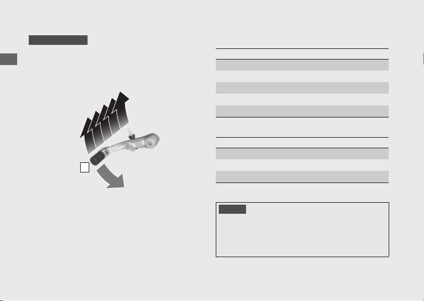
222
Operation Guide
Shifting Gears
Your vehicle transmission has 6 forward gears
in a one-down, five-up shift pattern.
If you put the vehicle in gear with the side
stand down, the engine will shut off.
#
Recommended Shift Points
CRF1100A/A4
N
1
2
3
4
5
6
Shifting Up
From 1st to 2nd 12 mph (20 km/h)
From 2nd to 3rd 19 mph (30 km/h)
From 3rd to 4th 25 mph (40 km/h)
From 4th to 5th 31 mph (50 km/h)
From 5th to 6th 37 mph (60 km/h)
Shifting Down
From 6th to 5th 28 mph (45 km/h)
From 5th to 4th 22 mph (35 km/h)
From 4th to 3rd 16 mph (25 km/h)
NOTICE
Improper shifting can damage the engine, transmission,
and drive train. Also, coasting or towing the vehicle for
long distances with the engine off can damage the
transmission.
223
Operation Guide
Continued
Your vehicle is equipped with an automatically
controlled 6-speed transmission. It can be
shifted automatically (by AT MODE) or
manually (by MT MODE).
#
Recommended Shift Points
CRF1100D/D4
Shifting Up
From 1st to 2nd 12 mph (20 km/h)
From 2nd to 3rd 19 mph (30 km/h)
From 3rd to 4th 25 mph (40 km/h)
From 4th to 5th 31 mph (50 km/h)
From 5th to 6th 37 mph (60 km/h)
Shifting Down
From 6th to 5th 28 mph (45 km/h)
From 5th to 4th 23 mph (37 km/h)
From 4th to 3rd 20 mph (32 km/h)
NOTICE
Improper shifting can damage the engine, transmission,
and drive train. Also, coasting or towing the vehicle for
long distances with the engine off can damage the
transmission.
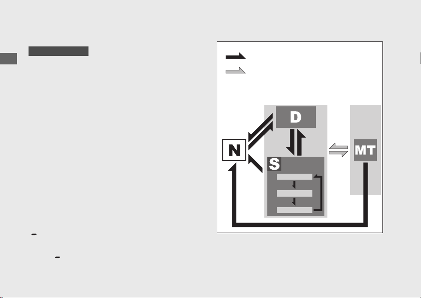
224
Shifting Gears
(Continued)
Operation Guide
Dual Clutch Transmission
In order to respond to rider demands in a
broad range of situations, the transmission is
equipped with three operating modes, AT
MODE (including D mode for regular
operation and three levels of S mode for
sporty riding); and MT MODE (MT mode for a
6-speed manual operation), which delivers the
same shift feel as a manual transmission.
u Always use the recommended tires and
sprockets to ensure correct Dual Clutch
Transmission operation.
The Dual Clutch Transmission system runs a
self check immediately after starting the
engine.
“ ” appears in the gear position indicator
window for a few seconds, then goes out.
While “ ” appears, you cannot shift into gear.
CRF1100D/D4
N-D switch
AT/MT switch
AT
MODE
MT
MODE
Level 1
Level 2
Level 3
225
Operation Guide
Continued
Neutral (N): Neutral is selected automatically
when you turn the ignition switch to the ON
position.
If neutral is not selected when you turn
the ignition switch to the ON position.
u Turn the ignition switch to the OFF position
and then to the ON position again.
u If neutral is still not selected after turning the
ignition switch to the OFF position, and then
to the ON position again.
(P313)
You may hear (click) noises when the
transmission shifts to Neutral (N). This is
normal.
When you can change between N and D
u Vehicle is stopped and the engine is idling.
u Throttle is completely closed. It is not possible
to change from Neutral to D mode while the
throttle is applied.
u You cannot change between N and D mode
while the wheels are rotating.
u Side stand is raised.
NOTICE
To prevent clutch damage, do not use the throttle to keep
the vehicle stopped uphill.

226
Shifting Gears
(Continued)
Operation Guide
AT MODE:
In this mode the gears are shifted
automatically according to your riding
conditions.
And also using the shift up switch (+) or shift
down switch (−), you can temporarily shift up or
down in AT MODE by using the shift switch.
These switches are convenient when you want to
temporarily down-shift in front of a curve, etc.
(P229)
You can choose between two modes within AT
MODE: D mode and S mode.
D mode (AT):
This is the standard mode when
AT MODE is selected. Select D mode for regular
operation and efficient fuel economy.
S mode (AT):
Select this mode while riding in
AT MODE when you need more power, such as
when overtaking, climbing hills, pulling away.
S mode has three levels of adjustment.
MT MODE:
MT MODE (6-speed manual
operation) You can choose between 6 gears in
this mode.
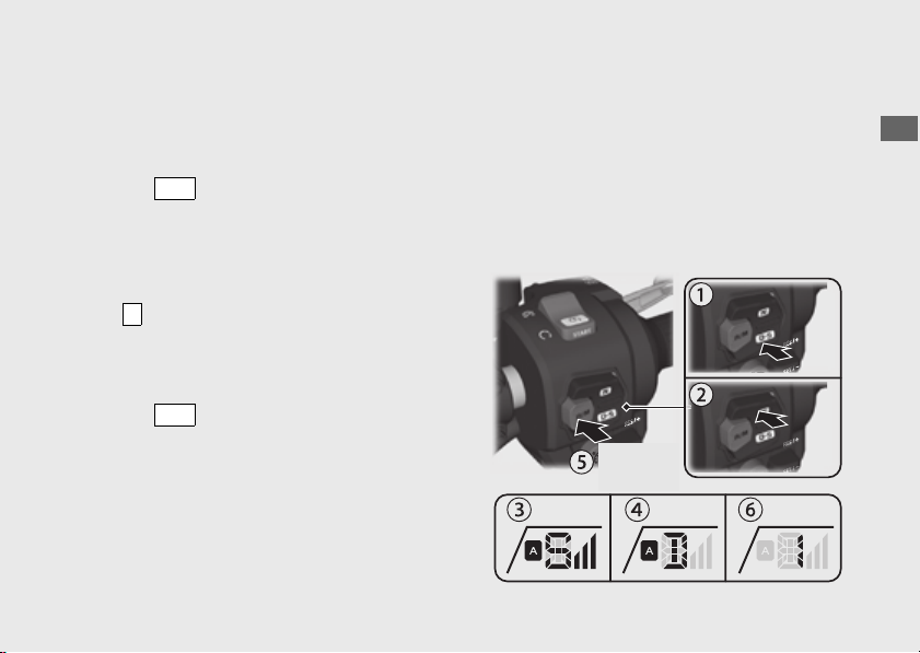
227
Operation Guide
Continued
Changing between Neutral and AT
MODE/MT MODE
Changing from Neutral (N) to AT MODE
Press the side of the N-D switch (
!a).
The D mode indicator comes on and first gear
is selected.
Changing from AT or MT MODE to
Neutral
Press on the N-D switch (
!b).
Changing between D mode and S mode
while in AT MODE
Press the side of the N-D switch. The S
or D is shown in the gear position indicator.
(
!c, !d).
Changing between AT MODE and MT
MODE
Press the AT/MT switch (
!e).
The AT indicator goes out while MT MODE is
selected (
!f
).
The gear position is displayed on the gear position
indicator while MT MODE is selected (
!f
).
D-S
N
D-S
AT/MT
Switch
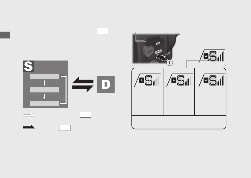
228
Shifting Gears
(Continued)
Operation Guide
S mode level selecting while in AT MODE
While in S mode, press and hold the side
of the N-D (
!a) switch.
u Close the throttle completely. Then select the
desired level of the S mode.
The selected level is maintained even when
the ignition switch is turned to the OFF
position, or transmission is switched to out of
S mode.
D-S
Level 1
Level 2
Level 3
Press and hold the side of the
N-D switch
D-S
Press the side of the N-D
switch
D-S
N-D switch
Level 1 Level 2 Level 3
Higher engine RPM can be used by
increasing the level.
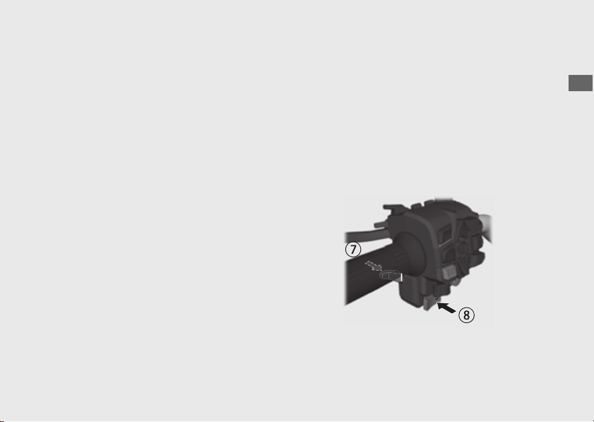
229
Operation Guide
Riding in MT MODE
Shift up and down with the shift up switch (+)
and shift down switch (−).
The selected gear is shown on the gear
position indicator.
u If the MT MODE is selected, the transmission
does not shift up automatically. Do not allow
the engine revs to go into the red zone.
u The transmission automatically shifts down
when you slow down, even in MT MODE.
u You will start from 1st gear even if MT MODE
is selected.
Gear shift operation
Shifting Up:
Press the shift up switch (+) (
!g).
Shifting Down:
Press the shift down switch (−) (
!h).
You cannot continue shifting gear by keeping
the shift switch pressed.
To continue shifting gear release the switch
and press it again.
Shift Limit
You cannot downshift if the engine will exceed
the rev limit.
230
Operation Guide
Cruise Control
The cruise control system allows you to
maintain a steady speed within a specified
range.
The available speed setting range and
operating gear are listed below:
When cruise control is on, your speed will still
vary slightly, particularly going up and down
hills.
Cruise control is intended for use only on
straight, uncongested highways. Do not use
cruise control on city streets, winding roads,
during bad weather, or at any other time
when you need total control of the throttle.
Available Speed
setting range
30 - 100 mph (50 –
160 km/h)
Operating gear From 4th to 6th gear
Available Speed
setting range
30 - 100 mph (50 –
160 km/h)
Operating gear From 3rd to 6th gear
CRF1100A/A4
CRF1100D/D4
3
WARNING
Improper use of the cruise control can
lead to a crash in which you could be
seriously hurt or killed.
Use the cruise control only when
travelling on open highways in good
weather.
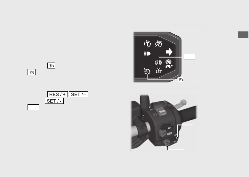
231
Operation Guide
Continued
#
To Set Cruise Control
!a Make sure the travelling speed and operating
gear are conformed to the requirements of
the system.
Any speed other than the available range will
not be memorized.
!b Press the cruise control main switch. (The
cruise control main indicator will come
on.)
!c Accelerate to the desired speed.
!d Push the cruise control
lever to side. (The cruise control
indicator will come on.) Your current
travelling speed is memorised.
SET
Cruise control
main indicator
Cruise control
SET indicator
SET
Cruise control
main switch
Cruise control
lever
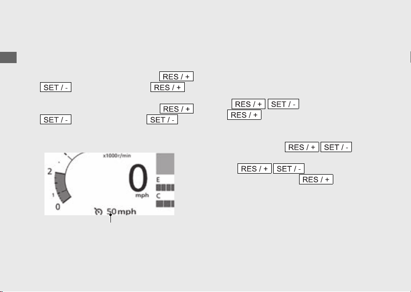
232
Cruise Control
(Continued)
Operation Guide
#
To Change the Set Speed
To Fine Tune the Set Speed
!a Select the riding information. (P38)
!b To increase the set speed: tap the
cruise control lever to
side.
To decrease the set speed: tap the
cruise control lever to side.
!c The set speed is displayed in the multi-
information display.
Each quick tap (brief push and release) on either
side will change your speed by 1 mph or 1 km/h
(depending on mileage meter set unit).
Any speed other than the possible setting range
will not be indicated (stops at the upper or lower
limit speed).
To Change the Set Speed Continuously
● To increase the set speed: push and hold
the cruise control lever
to side.
The system will accelerate your vehicle
automatically. When you reach the desired
speed, release the cruise
control lever.
If the cruise control lever
is pushed and held to side
continuously, the set speed indicated in the
multi-information display stops at the upper
limit of the possible setting range.
Cruise control set speed
233
Operation Guide
Continued
● To decrease speed: push and hold the
cruise control lever to
side. The system will automatically
slow your vehicle. When you reach the
desired speed, release the
cruise control lever.
If the cruise control lever
is pushed and held to side
continuously, the set speed indicated in the
multi-information display stops at the lower
limit of the possible setting range.
To Manually Increase the Set Speed
!a Use the throttle to accelerate until you reach
the desired speed.
!b Push and release the
cruise control lever to side.
To Manually Increase Vehicle Speed
!a Use the throttle in the normal manner to
accelerate.
!b To return to the set speed, close the throttle
and coast without applying the brakes. The
cruise system will maintain the speed you
previously set.
#
To Cancel Cruise Control
To Disengage the System
● Press the cruise control main switch. (The
cruise control main indicator goes off
and the set speed will be erased from
memory.)

234
Cruise Control
(Continued)
Operation Guide
To Temporarily Disengage the System
!a Perform one of the following operations to
disengage the system temporarily. (
Cruise control SET indicator temporarily goes
off but the set speed remains in memory.)
● Apply the brake lever or pedal.
● Rotate the throttle grip past the
automatically closed position in the
deceleration direction.
●
Disengage the clutch or operate the
shift lever.
!b To resume cruise control:
● If you are still over 30 mph (50 km/h),
push and release the
cruise control lever to side.
● If you are under 30 mph (50 km/h), use
the throttle to increase road speed
above 30 mph (50 km/h) and then push
and release the
cruise control lever to side.
SET
CRF1100A/A4
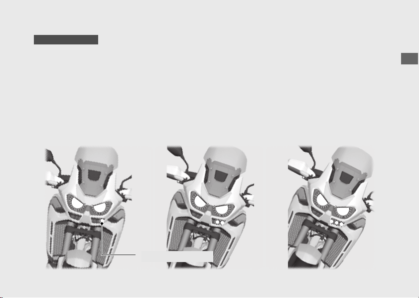
235
Operation Guide
Cornering Light
The cornering light lights up the direction of
travel of the vehicle when cornering.
Operating conditions:
●
Vehicle has been ridden at a speed of over 6
mph (10 km/h).
●
When the vehicle banking left or right.
Three-step lighting state is switched by the bank
angle.
CRF1100A4/D4
Cornering light
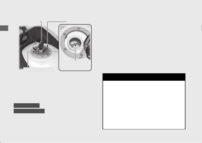
236
Operation Guide
Refueling
Do not fill with fuel above the level plate.
Fuel type: Unleaded gasoline only
Recommended fuel octane number:
Pump Octane Number (PON) 86 or higher.
Tank capacity:
4.97 US gal (18.8 L)
6.55 US gal (24.8 L)
#
Refueling and Fuel Guidelines (P13)
Opening the Fuel Fill Cap
Open the lock cover, insert the ignition key,
and turn it clockwise to open the fuel fill cap.
Closing the Fuel Fill Cap
!a After refueling, push the fuel fill cap closed
until it locks.
!b Remove the key and close the lock cover.
u The key cannot be removed if the fuel fill
cap is not locked.
Ignition key Lock cover
Fuel fill cap
Level plate
CRF1100A/D
CRF1100A4/D4
3
WARNING
Gasoline is highly flammable and
explosive. You can be burned or
seriously injured when handling fuel.
● Stop the engine, and keep heat,
sparks, and flames away.
● Only handle fuel outdoors.
● Wipe up spills immediately.
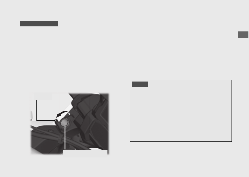
237
Operation Guide
Accessory Socket
The accessory socket is located in the left side
inner panel cover.
Use accessory devices at your own risk. In no
event shall Honda be liable for any damages
to your accessory device when in use.
Open the cover to access the socket.
Rated capacity is
24 W (12 V, 2 A).
u To prevent the battery from becoming weak
(or dead), keep the engine running while
drawing current from the socket.
u To prevent entry of foreign matter into the
socket, be sure to close the cover when the
socket is not used.
u Carefully secure all connected devices, as
vibration may cause damage to them or they
could shift unexpectedly.
CRF1100A4/D4
Cover
Accessory socket
NOTICE
●
Using any heat-generating accessory or improperly
rated accessory can damage the socket.
●
Do not use the socket in wet conditions, when or while
washing or any other wet conditions as these will
damage the socket.
●
Do not allow the accessory's harness to become
pinched or trapped.
●
Do not allow the accessory's harness to interfere with
the steering or controls.
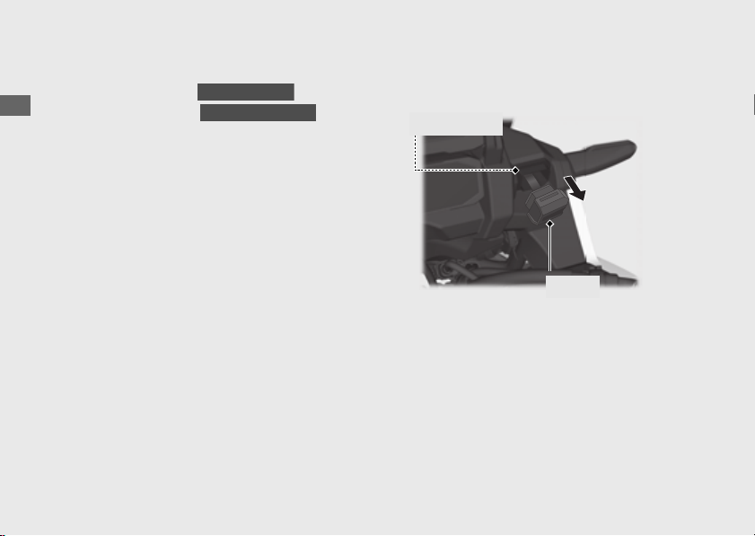
238
Operation Guide
USB Socket
The USB socket is located in the right side front
turn signal light cover ( ) or right
side inner panel cover ( ).
Use USB devices at your own risk. In no event
shall Honda be liable for any damage to your
USB device when in use.
Only USB devices within the following
specifications can be connected.
Open the cover to access the socket.
Rated capacity is
7.5 W (5 V, 1.5 A).
To connect your USB device
!a Open the cover to access the USB socket.
CRF1100A/D
CRF1100A4/D4
Cover
USB socket
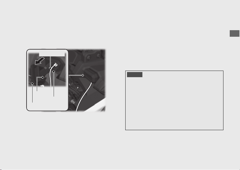
239
Operation Guide
!b Connect a certified USB cable to the socket.
!c Route the USB cable along the recess.
!d Pass the USB cable through the cover slit and
close the cover.
u
To prevent the battery from becoming weak (or
dead), keep the engine running while drawing
current from the socket.
u
To prevent entry of foreign matter into the
socket, be sure to close the cover.
u
Carefully secure all connected devices, as
vibration may cause damage to them or they
could shift unexpectedly.
USB cable
Cover
Slit
Recess
NOTICE
●
Using any heat-generating USB devices or improperly
rated USB devices can damage the socket.
●
Do not use the USB socket in wet conditions, when or
while washing or any other wet conditions as these will
damage the USB socket.
●
Do not allow the USB cable to become pinched or
trapped.
●
Do not allow the USB cable to interfere with the steering
or controls.
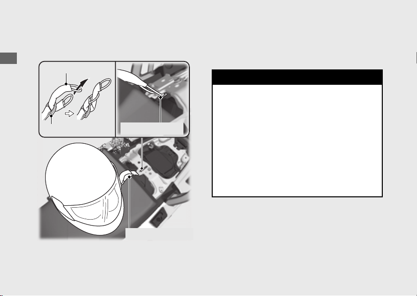
240
Operation Guide
Storage Equipment
Helmet holder
A helmet holder is located under the rear seat.
u Use the helmet holder only when parked.
#
Removing the rear seat (P273)
Helmet set wire
Helmet D-ring
Helmet set wire
Helmet holder
3
WARNING
Riding with a helmet attached to the
holder can interfere with your ability to
safely operate the vehicle and could lead
to a crash in which you can be seriously
hurt or killed.
Use the helmet holder only while parked.
Do not ride with a helmet secured by the
holder.
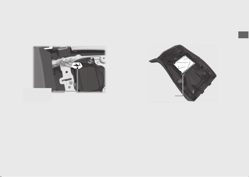
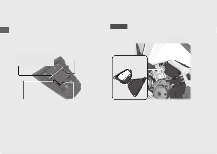
242
Storage Equipment
(Continued)
Operation Guide
Fuse Puller, Hex Wrench,
Standard/Phillips Screwdriver,
Screwdriver Handle
The fuse puller, hex wrench, standard/phillips
screwdriver and screwdriver handle are
located on the underside of the rear seat.
#
Removing the rear seat (P273)
Tool Kit
The tool kit is located in the tool box.
#
Removing the tool box (P274)
Hex wrench
Fuse puller
Screwdriver handle
Standard/Phillips
screwdriver
Canada
Tool box
Tool kit
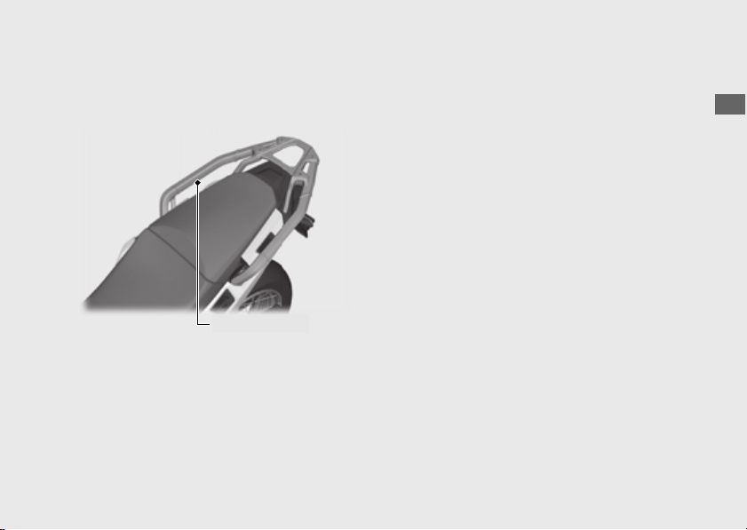
243
Operation Guide
Rear Carrier
Never exceed the maximum weight limit.
Maximum Weight: 22 lb (10 kg)
Rear carrier

Maintenance
Please read “Importance of Maintenance” and “Maintenance Fundamentals” carefully
before attempting any maintenance. Refer to “Specifications” for service data.
Importance of Maintenance .................... P. 245
Maintenance Schedule ............................. P. 247
Maintenance Record................................. P. 250
Maintenance Fundamentals..................... P. 251
Tools ........................................................... P. 266
Removing & Installing Body
Components............................................. P. 267
Battery.................................................................. P. 267
Battery Box Cover ............................................. P. 268
Clip........................................................................ P. 269
Front Seat............................................................ P. 270
Rear Seat ............................................................. P. 273
Tool Box............................................................... P. 274
Spark Arrester ........................................... P. 275
Engine Oil ...................................................P. 277
Coolant ....................................................... P. 279
Brakes ......................................................... P. 281
Side Stand ..................................................P. 285
Drive Chain................................................. P. 286
Wheels ........................................................P. 288
Clutch..........................................................P. 290
Throttle.......................................................P. 293
Other Adjustments.................................... P. 294
Adjusting the Brake Lever ...............................P. 294
Adjusting the Front Suspension.....................P. 295
Adjusting the Rear Suspension ......................P. 299
Adjusting the Windscreen Height .................P. 305

245
Maintenance
Importance of Maintenance
Keeping your vehicle well-maintained is
absolutely essential to your safety and to protect
your investment, obtain maximum performance,
avoid breakdowns, and reduce air pollution.
Maintenance is the owner's responsibility. Be
sure to inspect your vehicle before each ride and
perform the periodic checks specified in the
Maintenance Schedule.
2 P. 247
For information about the exhaust emission and
noise emission requirements of the U.S.
Environmental Protection Agency (EPA), the
California Air Resources Board (CARB), and the
Environment and Climate Change Canada
(ECCC).
2 P. 353
Maintenance, replacement or repair of the
emission control devices and systems may
be performed by any vehicle repair
establishment or individual using parts
that are “certified” to EPA standards.
Importance of Maintenance
3
WARNING
Improperly maintaining your vehicle or
failing to correct a problem before you
ride can cause a crash in which you can
be seriously hurt or killed.
Always follow the inspection and
maintenance recommendations and
schedules in this owner's manual.
USA

Importance of Maintenance
246
Maintenance
Always read the maintenance instructions before
you begin each task and make sure that you
have the tools, parts, and skills required.
We cannot warn you of every conceivable
hazard that can arise in performing
maintenance. Only you can decide whether or
not you should perform a given task.
Follow these guidelines when performing
maintenance.
● Stop the engine and remove the key.
● Place your vehicle on a firm, level surface
using the side stand or a maintenance stand to
provide support.
● Allow the engine, muffler, brakes, and other
high-temperature parts to cool before
servicing as you can get burned.
● Run the engine only when instructed, and do
so in a well-ventilated area.
Maintenance Safety

247
Continued
Maintenance
Maintenance Schedule
The maintenance schedule specifies the
maintenance requirements necessary to
ensure safe, dependable performance, and
proper emission control.
Maintenance work should be performed in
accordance with Honda's standards and
specifications by properly trained and
equipped technicians. Your dealer meets all of
these requirements. All scheduled
maintenance is considered a normal owner
operating cost and will be charged to you by
your dealer. Keeping an accurate
maintenance record will help ensure your
vehicle is properly maintained.
2 P. 250
Make sure whoever performs the scheduled
maintenance completes the maintenance
record. Retain all service documents. If you sell
your vehicle, these service documents should
be transferred with the vehicle to the new
owner.
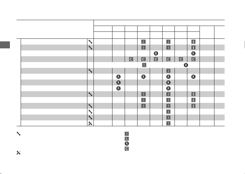
Maintenance Schedule
248
Maintenance
Items
Frequency
*1
× 1,000 mi
0.6 4 8 12162024
Regular
Replace
Refer
to
page
× 1,000 km
1.0 6.4 12.8 19.2 25.6 32.0 38.4
Emission-Related Items
Fuel Line –
Throttle Operation 293
Air Cleaner
*2
–
Crankcase Breather
*3
–
Spark Plug Every 16,000 mi (25,600 km): Every 32,000 mi (51,200 km): –
Valve Clearance –
Engine Oil
1 Year
–
Engine Oil Filter –
Clutch Oil Filter
*8
–
Engine Idle Speed –
Radiator Coolant
*7
3 Years
279
Cooling System –
Secondary Air Supply System –
Evaporative Emission Control System
*4
–
Exhaust Gas Control Actuator Cable –
Maintenance Level Maintenance Legend
: Intermediate. We recommend service by your dealer, unless you
have the necessary tools and are mechanically skilled.
Procedures are provided in an official Honda Service Manual
(
2 P. 359
).
:
:
:
:
Inspect (clean, adjust, lubricate, or replace, if necessary)
Lubricate
Replace
Clean
: Technical. In the interest of safety, have your vehicle serviced by
your dealer.
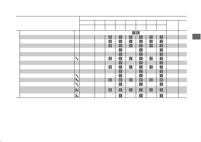
Maintenance Schedule
249
Maintenance
Notes:
*1 :
At higher odometer readings, repeat at the frequency
interval established here.
*2 :
Service more frequently when riding in unusually wet or
dusty areas.
*3 :
Service more frequently when riding in rain or at full
throttle.
*4 :
50 STATE (meets California).
*5 :
Service more frequently when riding OFF-ROAD.
*6 :
USA only.
*7 :
Replacement requires mechanical skill.
*8 :
CRF1100D/D4 only
*9 :
CRF1100A/A4 only
Items
Frequency
*1
× 1,000 mi
0.6 4 8 12162024
Regular
Replace
Refer
to
page
× 1,000 km
1.0 6.4 12.8 19.2 25.6 32.0 38.4
Non-Emission-Related Items
Drive Chain
*5
Every 600 mi (1,000 km): 286
Drive Chain Slider –
Brake Fluid
*7
2 Years
281
Brake Pads Wear 282
Brake System 251
Brake Light Switch 284
Brake Lock Operation
*8
283
Headlight Aim –
Clutch System
*9
290
Side Stand 285
Suspension –
Spark Arrester
*6
–
Nuts, Bolts, Fasteners
*5
–
Wheels/Tires
*5
261,
288
Steering Head Bearings –
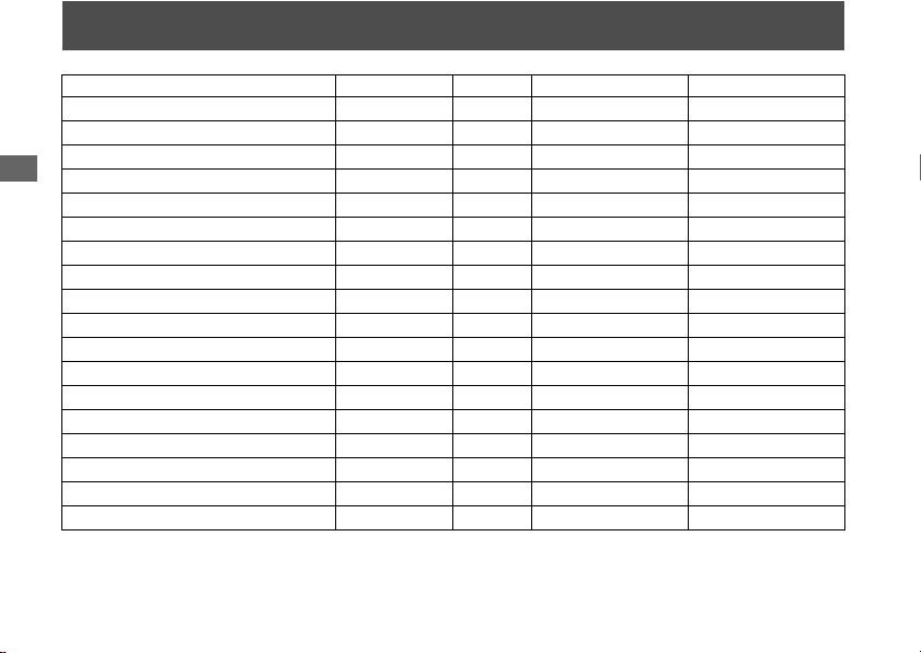
250
Maintenance
Maintenance Record
Distance Odometer Date Performed By: Notes
600 miles (1,000 km)
4,000 miles (6,400 km)
8,000 miles (12,800 km)
12,000 miles (19,200 km)
16,000 miles (25,600 km)
20,000 miles (32,000 km)
24,000 miles (38,400 km)
28,000 miles (44,800 km)
32,000 miles (51,200 km)
36,000 miles (57,600 km)
40,000 miles (64,000 km)
44,000 miles (70,400 km)
48,000 miles (76,800 km)
52,000 miles (83,200 km)
56,000 miles (89,600 km)
60,000 miles (96,000 km)
64,000 miles (102,400 km)
68,000 miles (108,800 km)

251
Continued
Maintenance
Maintenance Fundamentals
To ensure safety, it is your responsibility to
perform a pre-ride inspection and make sure
that any problem you find is corrected. A pre-
ride inspection is a must, not only for safety, but
because having a breakdown, or even a flat tire,
can be a major inconvenience.
Before riding on-road, or returning to pavement
after riding off-road, take a few moments to walk
around your vehicle and look for any loose parts
or anything that appears unusual.
Also check the following.
● Tire tread wear and air pressures are within
limits
2 P. 261
● Lights, horn, and turn signals operate normally
● Check the condition of the drive chain. Adjust
slack and lubricate as needed
2 P. 259
Check the following items if you are carrying a
passenger or cargo:
● Combined weight is within load limits 2 P. 373
● Cargo is secured properly
● Suspension is adjusted to suit load 2 P. 295
2 P. 299
Check the following items after you get on your
vehicle:
● Throttle action moves smoothly without
binding
2 P. 293
● Brake lever and pedal operate normally
● Check the fuel level and refuel when needed
2 P. 13, 2 P. 236
● Engine stop switch functions properly 2 P. 114
Pre-ride Inspection

Maintenance Fundamentals
252
Maintenance
Check the following items at regular intervals:
● Oil level is between the upper and lower level
marks
2 P. 277
● Brake fluid level is
Front: above the LOWER level mark
2 P. 281
Rear: between the UPPER and LOWER level
marks
2 P. 281
● Engine coolant level is between the UPPER
and LOWER level marks
2 P. 279
● Side stand functions properly 2 P. 285
●
● Parking brake works properly 2 P. 283
Before riding off-road check all of the preceding
plus the following:
● Make sure spokes are tight. Check the rims for
any damage
2 P. 288
● Oil level is between the upper and lower marks
2 P. 277
● Check the fuel level and refuel when needed
2 P. 13, 2 P. 236
● Be sure the fuel fill cap is securely fastened
2 P. 236
●
● Clutch lever operates smoothly. Adjust
freeplay if necessary
2 P. 290
● Check for loose cables and other parts, and
anything that appears abnormal
● Use a wrench to check the tightness of all
accessible nuts, bolts and fasteners
CRF1100D/D4
CRF1100A/A4
Maintenance Fundamentals
253
Maintenance
You should also perform other periodic
maintenance checks at least once a month
regardless of how often you ride, or more often
if you ride frequently.
Also, check the odometer reading against the
Maintenance Schedule and perform all
maintenance that is due.
2 P. 247
Periodic Checks
Tires and wheels
Check the air pressure (2 P. 261), examine tread for wear and
damage (2 P. 262), and check the wheels for damage.
Fluid levels
Check the engine oil level (2 P. 277), engine coolant level (2 P. 279),
and brake fluid level (2 P. 281).
Lights
Check that the headlight, cornering light (CRF1100A4/D4 only), brake
light, taillight, license plate light, and turn signals are working properly.
Controls
Check the freeplay of the clutch lever (CRF1100A/A4 only) (2 P. 290),
throttle grip (2 P. 293), front brake lever (2 P. 294), rear brake pedal
and parking brake (CRF1100D/D4 only) (2 P. 283) operate properly.
Drive chain
Check the slack (2 P. 286), adjust the slack, and lubricate (2 P. 260)
as needed.
Fuses Check that you have a full supply of spare fuses.
Nuts & bolts Check the major nuts and bolts, and tighten as needed.
Crankcase breather
Service the crankcase breather more frequently if your vehicle is
ridden in the rain or often at full throttle. Service the breather if you
can see deposits in the transparent section of the drain tube.
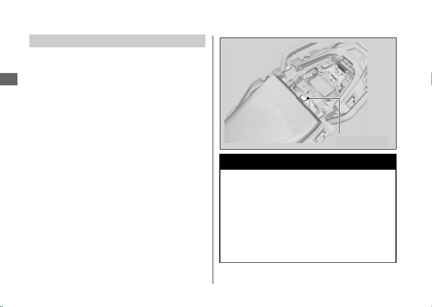
Maintenance Fundamentals
254
Maintenance
Always use Honda Genuine Parts or their
equivalents to ensure reliability and safety.
When ordering colored components, specify the
model name, color, and code mentioned on the
color label.
The color label is attached to the rear fender
under the rear seat.
2 P. 273
Replacing Parts
3
WARNING
Installing non-Honda parts may make
your vehicle unsafe and cause a crash in
which you can be seriously hurt or killed.
Always use Honda Genuine Parts or
equivalents that have been designed
and approved for your vehicle.
Color label

Maintenance Fundamentals
255
Continued
Maintenance
Your vehicle has a lithium-ion (li-ion) battery.
Clean the battery terminals if they become dirty
or corroded.
#
What to do in an emergency
If any of the following occurs, immediately see
your doctor.
● Electrolyte splashes into your eyes:
u Wash your eyes repeatedly with cool water
for at 15 minutes. Using water under
pressure can damage your eyes.
● Electrolyte splashes onto your skin:
u Remove affected clothing and wash your
skin thoroughly using water.
● Electrolyte splashes into your mouth
u Rinse mouth thoroughly with water, and do
not swallow.
Lithium-Ion (Li-Ion) Battery
NOTICE
An improperly disposed of battery can be harmful to the
environment and human health.
Always confirm local regulations for proper battery
disposal instruction.
3
WARNING
The battery contains flammable organic
solvent as electrolyte.
You can be burned or seriously injured if
the battery is handled improperly.
● Keep the battery away from heat,
sparks, and flames.
● Keep the battery out of the reach of
children.
● Do not disassemble or modify the
battery or battery terminals.
● Do not short-circuit the battery with
metal tools or other metal objects.
● Do not subject the battery to impacts.
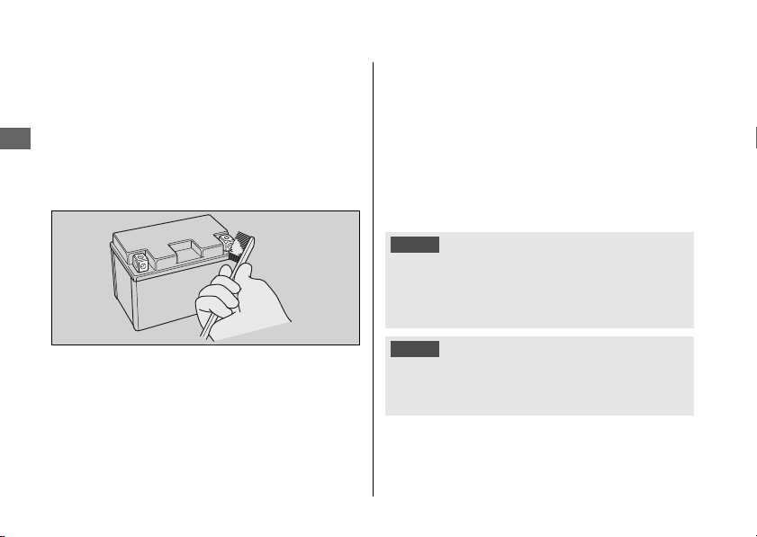
Maintenance Fundamentals
256
Maintenance
#
Cleaning the Battery Terminals
1.
Remove the battery. 2 P. 267
2.
If the terminals are starting to corrode and are
coated with a white substance, wash with
warm water and wipe clean.
3.
If the terminals are heavily corroded, clean
and polish the terminals with a wire brush or
sandpaper. Wear safety glasses.
4.
After cleaning, reinstall the battery.
The battery has a limited life span. Consult your
dealer about when you should replace the
battery. Always replace the battery with another
lithium-ion (li-ion) battery of the same type.
#
Charging
If you use electrical accessories that drain the
battery or you do not ride frequently, we
recommend that you charge the battery every
30 days using a charger recommended by your
lithium-ion (li-ion) battery manufacturer.
Contact your dealer before charging the battery.
Make sure the ignition switch is in the OFF
position before charging the battery.
NOTICE
Only use a charger recommended by your lithium-ion (li-
ion) battery manufacturer. Using a battery charger that is
not recommended can cause permanent damage to your
battery.
NOTICE
Improper charging can damage the battery. If you can’t
charge the battery or it appears unable to hold a charge,
contact your dealer.
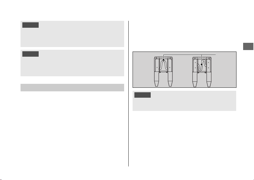
Maintenance Fundamentals
257
Maintenance
Fuses protect the electrical circuits on your
vehicle. If something electrical on your vehicle
stops working, check for and replace any blown
fuses.
2 P. 334
#
Inspecting and Replacing Fuses
Turn the ignition switch to the OFF position to
remove and inspect fuses. If a fuse is blown,
replace with a fuse of the same rating. For fuse
ratings, see “Specifications.”
2 P. 376
If a fuse fails repeatedly, you likely have an
electrical fault. Have your vehicle inspected by
your dealer.
NOTICE
Do not jump-start, as this can damage your vehicle's
electrical system and battery.
Bump starting is not recommended.
NOTICE
Installing non-Honda electrical accessories can overload
the electrical system, discharging the battery and possibly
damaging the system.
Fuses
NOTICE
Replacing a fuse with one that has a higher rating greatly
increases the chance of damage to the electrical system.
Blown
fuse

Maintenance Fundamentals
258
Maintenance
Engine oil consumption varies and oil quality
deteriorates according to riding conditions and
time elapsed.
Check the engine oil level regularly, and add the
recommended engine oil if necessary. Dirty oil or
old oil should be changed as soon as possible.
#
Selecting the Engine Oil
For recommended engine oil, see
“Specifications.”
2 P. 375
If you use non-Honda engine oil, check the label
to make sure that the oil satisfies all of the
following standards:
● JASO T 903 standard
*1
: MA
● SAE standard
*2
: 10W-30
● API classification
*3
: SJ or higher
*1.
The JASO T 903 standard is an index for engine oils
for 4-stroke motorcycle engines. There are two
classes: MA and MB. For example, the following label
shows the MA classification.
*2.
The SAE standard grades oils by their viscosity.
*3.
The API classification specifies the quality and
performance rating of engine oils. Use SJ or higher
oils, excluding oils marked as “Energy Conserving” or
“Resource Conserving” on the circular API service
symbol.
Engine Oil
Oil code
Oil classification
Not recommended Recommended
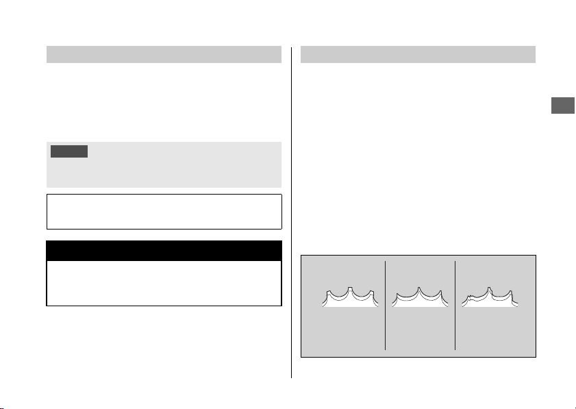
Maintenance Fundamentals
259
Continued
Maintenance
Do not add or replace brake fluid, except in an
emergency. Use only fresh brake fluid from a
sealed container. If you do add fluid, have the
brake system serviced by your dealer as soon as
possible.
The drive chain must be inspected and
lubricated regularly. Inspect the chain more
frequently if you often ride on bad roads, ride at
high speed, or ride with repeated fast
acceleration.
2 P. 286
If the chain does not move smoothly, makes
strange noises, has damaged rollers, has loose
pins, has missing O-rings, or kinks, have the
chain inspected by your dealer.
Also inspect the drive sprocket and driven
sprocket. If either has worn or damaged teeth,
have the sprocket replaced by your dealer.
Brake Fluid
NOTICE
Brake fluid can damage plastic and painted surfaces.
Wipe up spills immediately and wash thoroughly.
Recommended brake fluid:
Honda DOT 4 Brake Fluid or equivalent
3
WARNING
Clean filler cap before removing. Use
only DOT 4 fluid from a sealed container.
Drive Chain
Normal
(GOOD)
Worn
(REPLACE)
Damaged
(REPLACE)
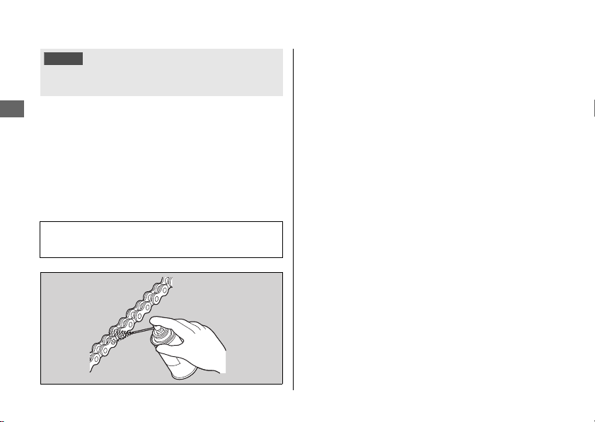
Maintenance Fundamentals
260
Maintenance
#
Cleaning and Lubricating
After inspecting the slack, clean the chain and
sprockets while rotating the rear wheel. Use a dry
cloth with chain cleaner designed specifically for O-
ring chains, or neutral detergent. Use a soft brush if
the chain is dirty.
After cleaning, wipe dry and lubricate with the
recommended lubricant.
Do not use a steam cleaner, a high pressure
cleaner, a wire brush, volatile solvent such as
gasoline and benzene, abrasive cleaner, chain
cleaner or lubricant NOT designed specifically
for O-ring chains as these can damage the
rubber O-ring seals.
Avoid getting lubricant on the brakes or tires.
Avoid applying excess chain lubricant to prevent
spray onto your clothes and the vehicle.
NOTICE
Use of a new chain with worn sprockets will cause rapid
chain wear.
Recommended lubricant:
Pro Honda HP Chain Lube or equivalent
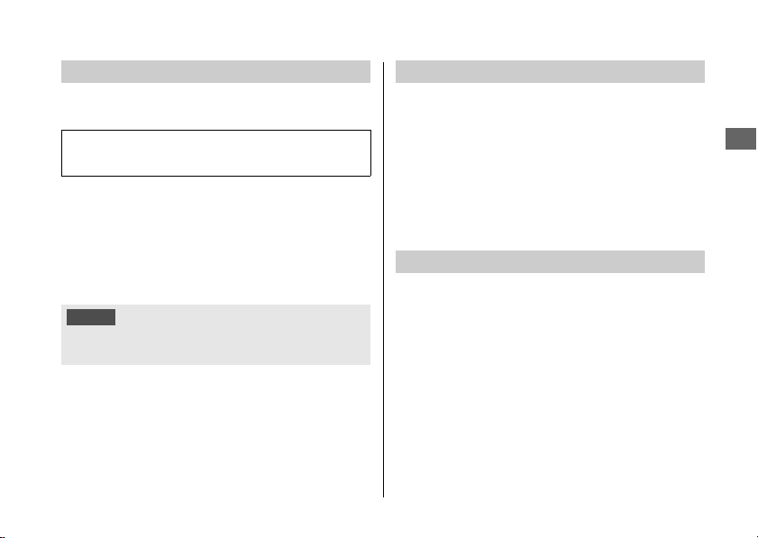
Maintenance Fundamentals
261
Continued
Maintenance
Pro Honda HP Coolant is a pre-mixed solution of
antifreeze and distilled water.
A concentration of antifreeze below 40% will not
provide proper corrosion and cold temperature
protection.
A concentration of up to 60% will provide better
protection in colder climates.
Service more frequently when riding in rain, at
full throttle, or after the vehicle is washed or
overturned. Service if the deposit level can be
seen in the transparent section of the drain tube.
If the drain tube overflows, the air filter may
become contaminated with engine oil causing
poor engine performance.
#
Checking the Air Pressure
Visually inspect your tires and use an air pressure
gauge to measure the air pressure before each off-
road ride and whenever you return to pavement
after riding off-road. If you only ride on pavement,
check the pressure at least once a month or any
time you think the tires look low. Always check air
pressure when your tires are cold.
Recommended Coolant
Concentration:
50% antifreeze and 50% distilled water
NOTICE
Using coolant not specified for aluminum engines or tap/
mineral water can cause corrosion.
Crankcase Breathers
Tires (Inspecting/Replacing)
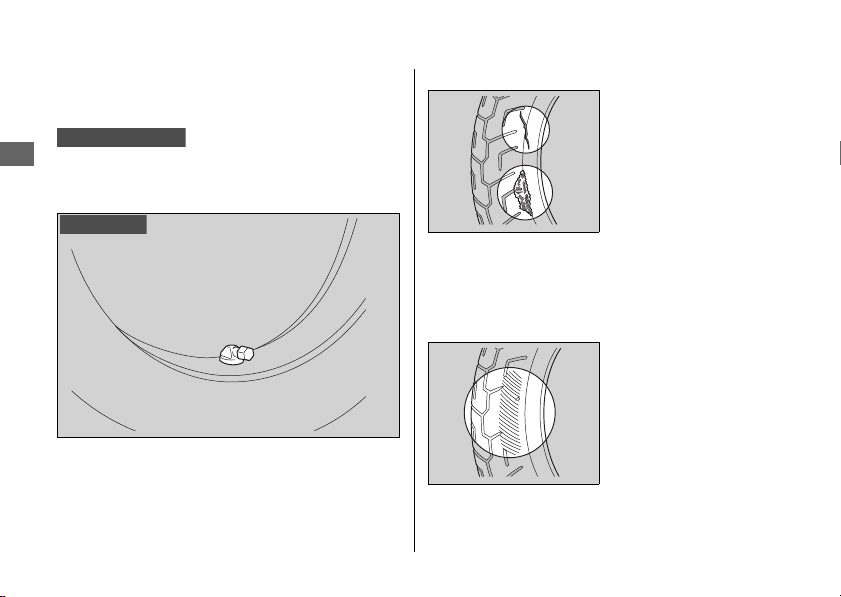
Maintenance Fundamentals
262
Maintenance
If you decide to adjust the tire pressure for a
particular off-road riding condition, make
changes a little at a time.
Even if the direction of the valve stem is changed,
do not return it to the original position. Have
your vehicle inspected by your dealer.
#
Inspecting for Damage
Inspect the tires for
cuts, slits, or cracks
that expose fabric or
cords, or nails or other
foreign objects
embedded in the side
of the tire or the tread.
Also inspect for any
unusual bumps or bulges in the side walls of the
tires.
#
Inspecting for Abnormal Wear
Inspect the tires for
signs of abnormal
wear on the contact
surface.
CRF1100A4/D4
Right side
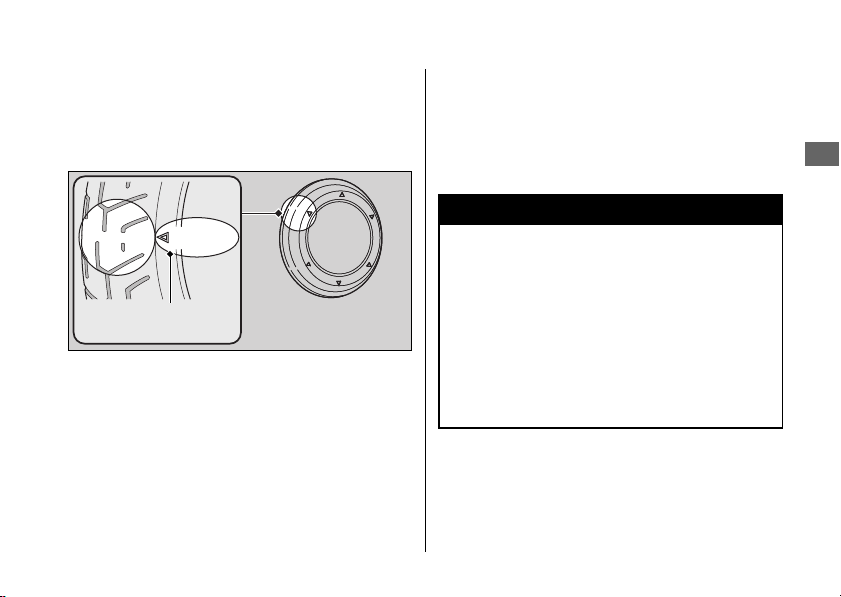
Maintenance Fundamentals
263
Continued
Maintenance
#
Inspecting Tread Depth
Inspect the tread wear indicators. If they become
visible, replace the tires immediately.
For safe riding, you should replace the tires when
the minimum tread depth is reached.
#
Inspecting Rims and Valve Stems
Inspect the rims for damage and loose spokes.
Also inspect the valve stems for their positions.
A tilted valve stem indicates the tube is slipping
inside the tire or the tire is slipping on the rim.
See your dealer.
Wear indicator
location mark
or TWI
3
WARNING
Riding on tires that are excessively worn
or improperly inflated can cause a crash
in which you can be seriously hurt or
killed.
Follow all instructions in this owner's
manual regarding tire inflation and
maintenance.

Maintenance Fundamentals
264
Maintenance
Have your tires replaced by your dealer.
For recommended tires, air pressure and
minimum tread depth, see “Specifications.”
2 P. 374
Follow these guidelines whenever you replace
tires.
● Use the recommended tires or equivalents of
the same size, construction, speed rating, and
load range.
● Have the wheel balanced with Honda Genuine
balance weights or equivalent after the tire is
installed.
●
Do not install a tube inside a tubeless tire on
this vehicle. Excessive heat build-up can cause
the tube to burst.
●
Use only tubeless tires on this vehicle.
The rims are designed for tubeless tires, and
during hard acceleration or braking, a tube-
type tire could slip on the rim and cause the
tire to rapidly deflate.
● Remember to replace the inner tube
whenever you replace a tire. The old tube will
probably be stretched, and it could fail if
installed in a new tire.
CRF1100A4/D4
CRF1100A4/D4
3
WARNING
Installing improper tires on your vehicle
can adversely affect handling and
stability, and can cause a crash in which
you can be seriously hurt or killed.
Always use the size and type of tires
recommended in this owner's manual.
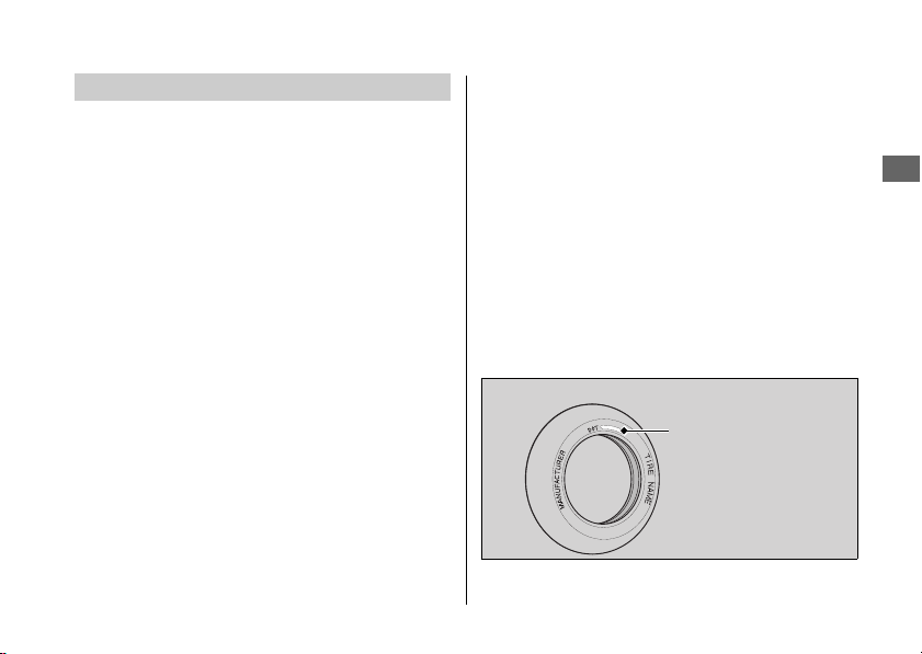
Maintenance Fundamentals
265
Maintenance
The service life of your tires is dependent on
many factors, including, but not limited to, riding
habits, road conditions, vehicle loading, tire air
pressure, maintenance history, speed, and
environmental conditions (even when the tires
are not in use).
In addition to your regular inspections and
maintenance, it is recommended that you have
annual inspections performed once the tires
reach 5 years old. It is also recommended that all
tires be removed from service after 10 years
from the date of manufacture, regardless of their
condition or state of wear.
The last four digits of the TIN (tire identification
number) indicate the date of manufacture.
#
Tire Identification Number (TIN)
The tire identification number (TIN) is a group of
numbers and letters located on the sidewall of
the tire.
Tire Service Life
!a !b!c
DOT XXXX XXXX 22 09
DOT: This indicates that the tire meets all
requirements of the U.S.
Department of Transportation.
!a XXXX: Factory code
!b XXXX: Tire type code
!c 22 09:
Date of manufacture (week & year).
Example: week 22 in year 09.
Tire Labeling Example
Tire identification
number (TIN)

266
Maintenance
Tools
You can perform some roadside repairs, minor
adjustments and parts replacement with the
provided tools.
The tool kit is stored in the tool box. 2 P. 242
● Spark plug wrench
● 10 × 14 mm Open end wrench
● 14 × 17 mm Open end wrench
● 19 mm Box end wrench
The helmet set wire is secured with the rear
fender under the rear seat. 2 P. 241
● Helmet set wire
The 5 mm hex wrench, standard/phillips
screwdriver, screwdriver handle and fuse puller
are located on the underside of the rear seat.
2 P. 242
● 5 mm Hex wrench
● Standard/Phillips screwdriver
● Screwdriver handle
● Fuse puller
Canada
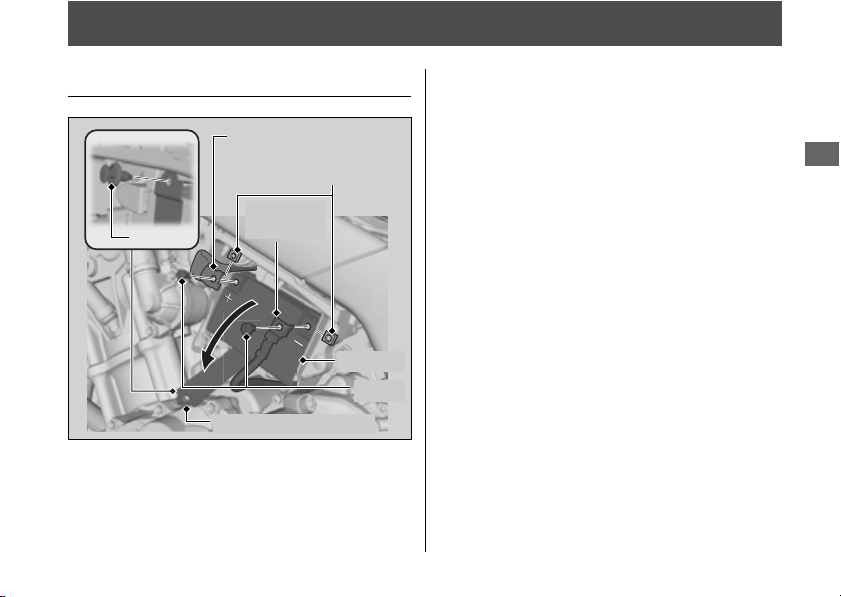
267
Maintenance
Removing & Installing Body Components
Battery
#
Removal
Make sure the ignition switch is in the OFF
position.
1.
Remove the tool box. 2 P. 274
2.
Disconnect the negative - terminal from
the battery.
3.
Disconnect the positive + terminal from
the battery.
4.
Remove the clip. 2 P. 269
5.
Open the battery box band.
6.
Remove the battery from the battery case
taking care not to drop the terminal nuts.
#
Installation
Install the parts in the reverse order of removal.
Always connect the positive
+
terminal first.
Make sure that bolts and nuts are tight.
Make sure the clock information is correct
after the battery is reconnected. 2 P. 88
For proper handling of the battery, see
“Maintenance Fundamentals.”
2 P. 255
“Battery Goes Dead.” 2 P. 333
Battery box band
Positive terminal
Negative
terminal
Battery
Bolts
Terminal nuts
Clip
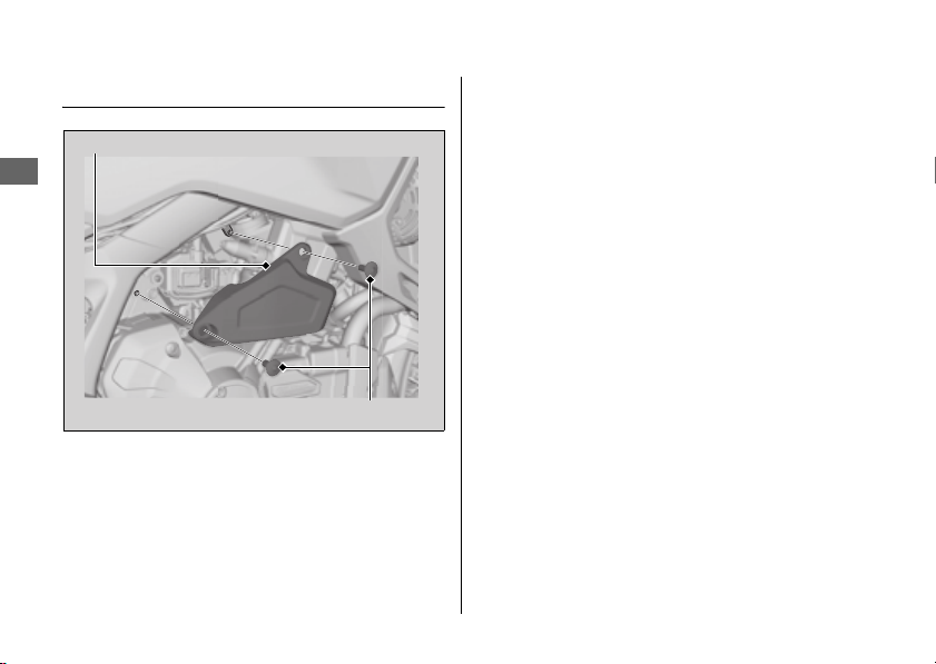
Removing & Installing Body Components u Battery Box Cover
268
Maintenance
Battery Box Cover
#
Removal
1.
Remove the bolts using the hex wrench
provided on the underside of the rear seat.
2 P. 242
2.
Remove the battery box cover.
#
Installation
Install the parts in the reverse order of
removal.
Battery box cover
Bolts
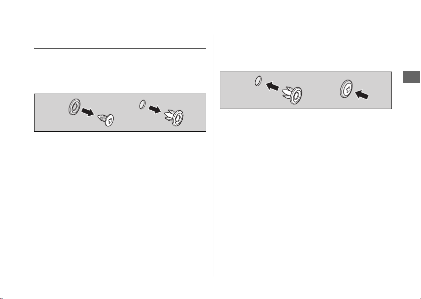
Removing & Installing Body Components u Clip
269
Maintenance
Clip
#
Removal
1.
Remove the pin by a Phillips screwdriver.
2.
Pull the clip out of the hole.
#
Installation
1.
Insert the clip into the hole.
2.
Push the pin in.
!a
!b
!a !b
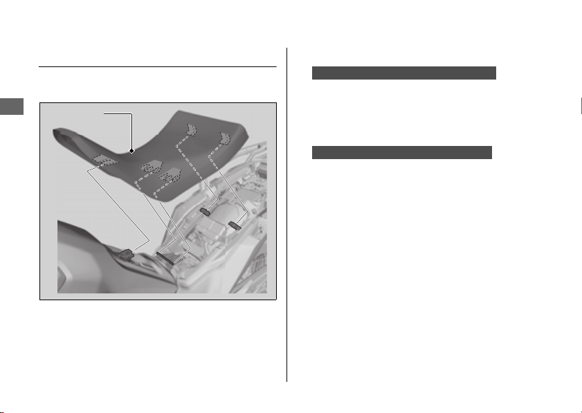
Removing & Installing Body Components u Front Seat
270
Maintenance
Front Seat
#
Removal
1.
Remove the rear seat. 2 P. 273
2.
Remove the front seat while pulling it
backward and upward.
#
Installation
1.
Insert the front lower prong and center
lower prongs into the front stay and center
stays on the fuel tank, and insert the rear
hooks into the upper slots.
Insert the front upper prong and center
upper prongs into the front stay and center
stays on the fuel tank, and insert the rear
hooks into the lower slots.
Front seat
When setting the high seat position:
When setting the low seat position:
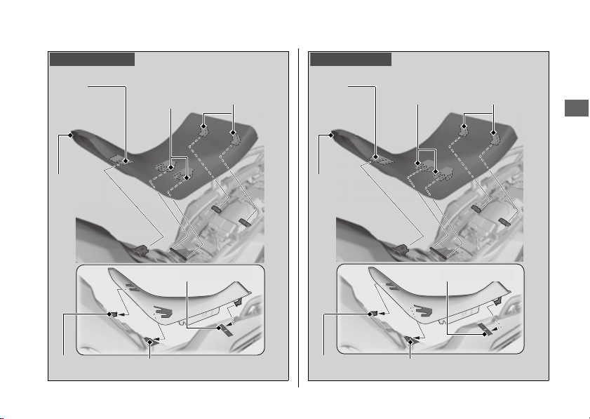
Removing & Installing Body Components u Front Seat
271
Continued
Maintenance
High position:
Front
lower
prong
Rear
hooks
Front
seat
Front stay
Upper slots
Center
lower
prongs
Center stays
Low position:
Center stays
Center
upper
prongs
Lower slots
Front stay
Front
seat
Rear
hooks
Front
upper
prong

Removing & Installing Body Components u Front Seat
272
Maintenance
2.
Install the front seat while pushing it
forward and downward.
u
Make sure that the seat is locked securely
in position by pulling it up lightly.
3.
Install the rear seat.
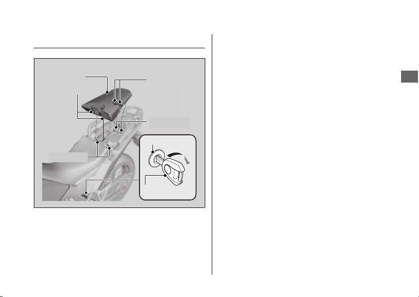
Removing & Installing Body Components u Rear Seat
273
Maintenance
Rear Seat
#
Removal
1.
Insert the ignition key into the seat lock.
2.
Turn the ignition key clockwise, then push
the rear seat forward and up.
#
Installation
1.
Insert the tabs into the recesses.
2.
Push down on the front of the rear seat
until it locks in place.
u Make sure that the seat is locked
securely in position by pulling it up
lightly.
The seat locks automatically when closed.
Take care not to lock your key in the
compartment under the rear seat.
Recesses
Tabs
Recesses
Tabs
Ignition key
Seat lock
Rear seat
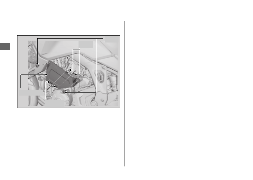
Removing & Installing Body Components u Tool Box
274
Maintenance
Tool Box
#
Removal
1.
Remove the bolts using the hex wrench
provided on the underside of the rear seat.
2 P. 242
2.
Remove the tool box by releasing its slots
from the tabs.
#
Installation
Install the parts in the reverse order of
removal.
Tool box
Bolts
Tabs
Slots
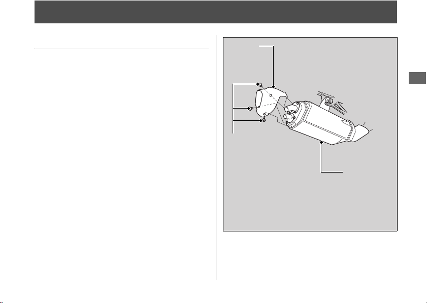
275
Continued
Maintenance
Spark Arrester
Cleaning the Spark Arrester
Regular servicing prevents carbon buildup
(which can diminish engine performance) and
also complies with USDA regulations for
regular maintenance to assure proper
function. The spark arrester prevents random
sparks from the combustion process in your
engine from reaching the environment.
u Because of possible fire hazard, do not ride
with the spark arrester removed.
Riding with the spark arrester removed will
also damage the surrounding parts.
1.
Allow the engine and muffler to cool.
2.
Remove the tail cap by removing the tail
cap mounting bolts from the muffler.
Tail cap
Tail cap
mounting bolts
Muffler
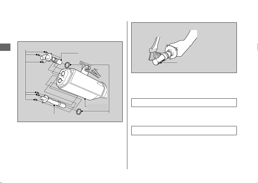
Spark Arrester u Cleaning the Spark Arrester
276
Maintenance
3.
Remove the spark arrester mounting bolts,
spark arresters and gaskets from the
muffler.
4.
Use a brush to remove carbon deposits
from the spark arrester screen. Be careful
to avoid damaging the spark arrester
screen. The spark arrester must be free of
breaks and holes. Replace, if necessary.
Check the gasket. Replace, if necessary.
5.
Install the gaskets and the spark arresters,
and tighten the spark arrester mounting
bolts.
6.
Install the tail cap and tighten the tail cap
mounting bolts.
Spark arrester
Gaskets
Spark arrester
Spark arrester mounting bolts
Muffler
Torque: 6.6 lbf·ft (9.0 N·m, 0.9 kgf·m)
Torque: 6.6 lbf·ft (9.0 N·m, 0.9 kgf·m)
Spark arrester screen
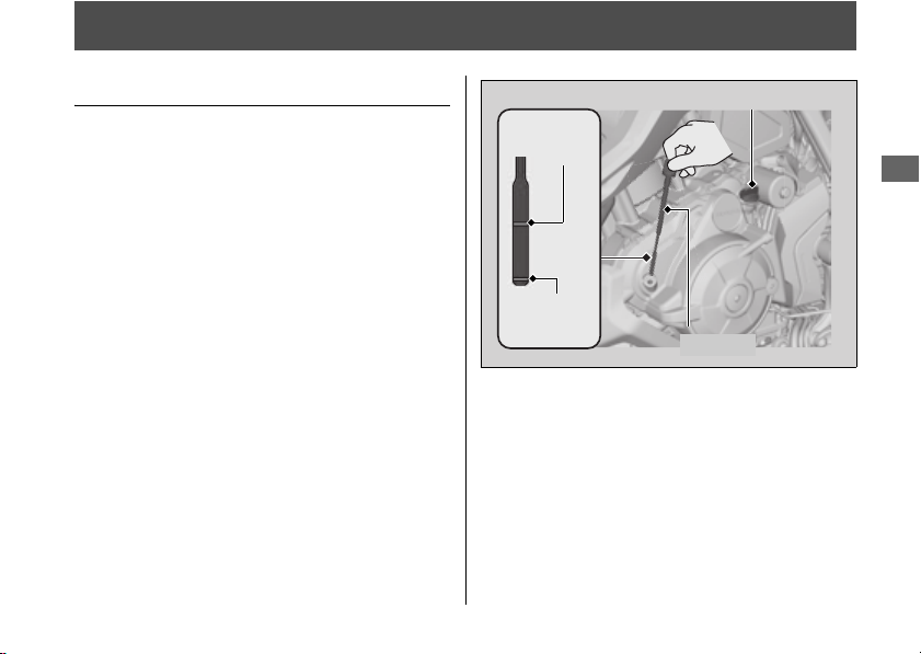
277
Maintenance
Engine Oil
Checking the Engine Oil
1.
Place your vehicle on its side stand on a
firm, level surface.
2.
If the engine is cold, idle the engine for 3 to
5 minutes.
3.
Turn the ignition switch to the OFF position
and wait for 2 to 3 minutes.
4.
Place your vehicle in an upright position on
a firm, level surface.
5.
Remove the dipstick and wipe it clean.
6.
Insert the dipstick until it seats, but don't
screw it in.
7.
Check that the oil level is between the
upper level and lower level marks on the
dipstick.
8.
Securely install the dipstick.
Oil fill cap
Upper
level
Lower
level
Dipstick
Engine Oil u Adding Engine Oil
278
Maintenance
Adding Engine Oil
If the engine oil is below or near the lower
level mark, add the recommended engine oil.
2 P. 258, 2 P. 375
1.
Remove the oil fill cap. Add the
recommended oil until it reaches the upper
level mark.
u Place your vehicle in an upright position
on a firm, level surface when checking
the oil level.
u Do not overfill above the upper level
mark.
u Make sure no foreign objects enter the
oil filler opening.
u Wipe up any spills immediately.
2.
Securely reinstall the oil fill cap.
For the recommended oil and oil selection
guidelines, see “Maintenance Fundamentals.”
2 P. 258
NOTICE
Overfilling with oil or operating with insufficient oil can
cause damage to your engine. Do not mix different brands
and grades of oil. They may affect lubrication and clutch
operation.
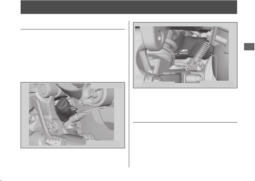
279
Continued
Maintenance
Coolant
Checking the Coolant
Check the coolant level in the reserve tank
while the engine is cold.
1.
Place your vehicle on a firm, level surface.
2.
Hold your vehicle in an upright position.
3.
Check that the coolant level is between the
UPPER level and LOWER level marks on the
reserve tank.
If the coolant level is dropping noticeably or the
reserve tank is empty, you likely have a serious
leak. Have your vehicle inspected by your dealer.
Adding Coolant
If the coolant level is below the LOWER level
mark, add the recommended coolant
(
2 P. 261) until the level reaches the UPPER
level mark.
Add fluid only from the reserve tank cap and
do not remove the radiator cap.
UPPER level
Reserve tank
Reserve tank
LOWER level
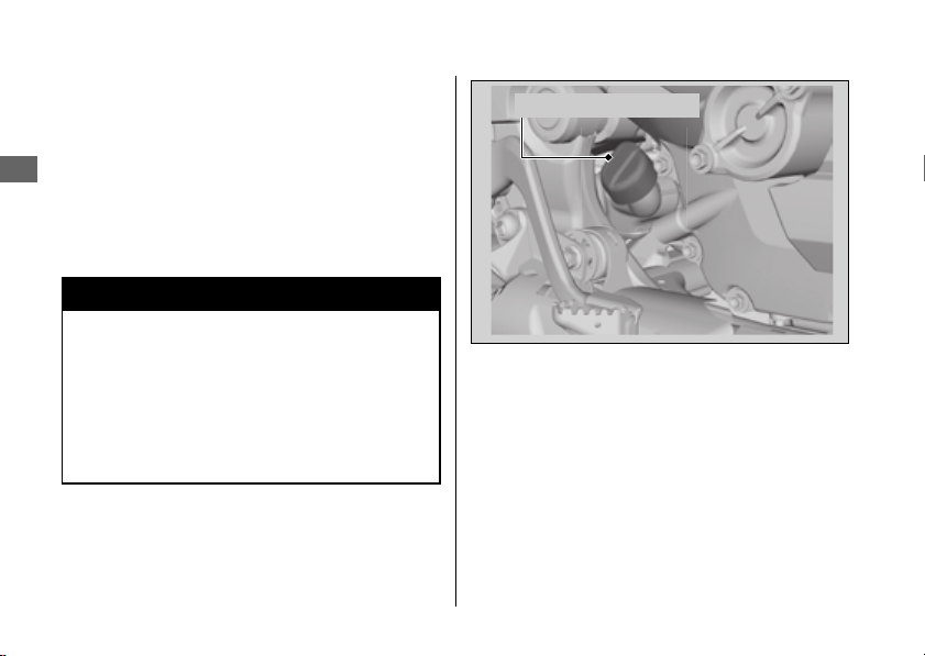
Coolant u Adding Coolant
280
Maintenance
1.
Remove the reserve tank cap and add fluid
while monitoring the coolant level.
u Do not overfill above the UPPER level
mark.
u Make sure no foreign objects enter the
reserve tank opening.
2.
Securely reinstall the reserve tank cap.
3
WARNING
Removing the radiator cap while the
engine is hot can cause the coolant to
spray out, potentially scalding you.
Always let the engine and radiator cool
down before removing the radiator cap.
Reserve tank cap
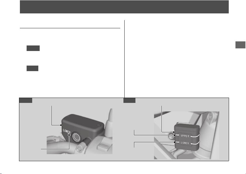
281
Maintenance
Brakes
Checking Brake Fluid
1.
Place your vehicle in an upright position on
a firm, level surface.
2.
Check that the brake fluid reservoir
is horizontal and that the fluid level is
above the LOWER level mark.
Check that the brake fluid reservoir is
horizontal and that the fluid level is
between the LOWER level and UPPER level
marks.
If the brake fluid level in either reservoir is
below the LOWER level mark or the brake
lever and pedal freeplay becomes excessive,
inspect the brake pads for wear.
If the brake pads are not worn, you most likely
have a leak. Have your vehicle inspected by
your dealer.
Front
Rear
Front brake fluid reservoir
LOWER
level mark
UPPER
level mark
LOWER
level mark
Rear brake fluid reservoir
Front
Rear
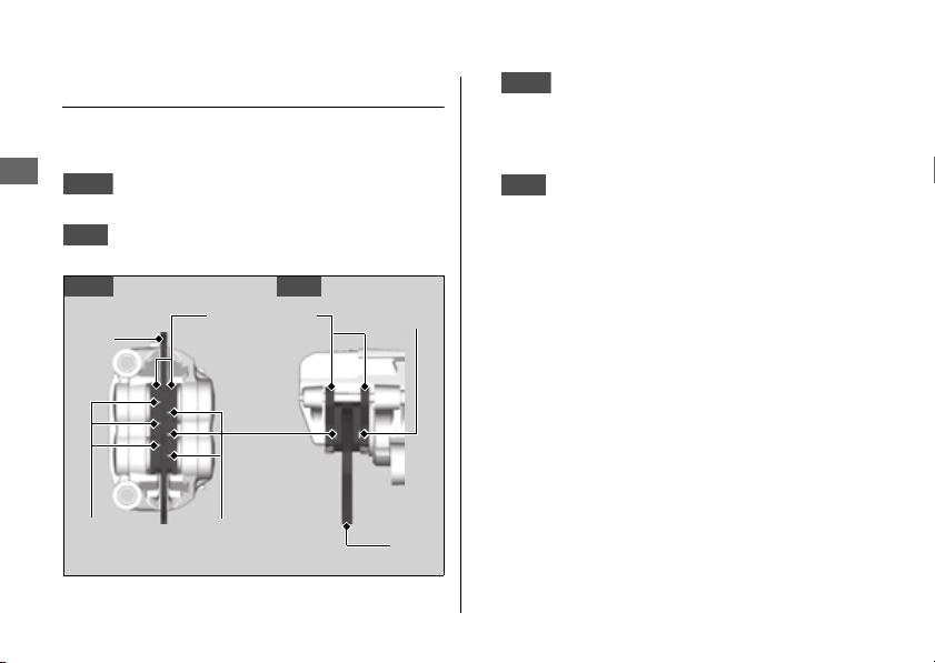
Brakes u Inspecting the Brake Pads
282
Maintenance
Inspecting the Brake Pads
Check the condition of the brake pad wear
indicators.
The pads need to be replaced if a brake
pad is worn to the bottom of the indicator.
The pads need to be replaced if a brake
pad is worn to the indicator.
1.
Inspect the brake pads from in front
of the brake caliper.
u Always inspect both left and right brake
calipers.
2.
Inspect the brake pads from the rear
right of the vehicle.
If necessary have the pads replaced by your
dealer.
Always replace both left and right brake pads
at the same time.
Front
Rear
Front
Rear
Brake Pads
Wear
indicator
Wear
indicators
Wear
indicators
Disc
Disc
Front
Rear
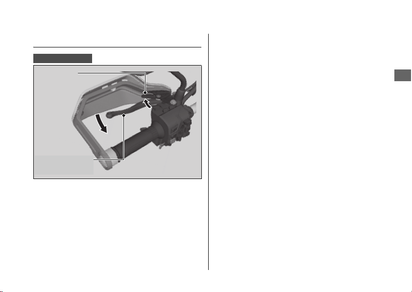
Brakes u Checking the Parking Brake
283
Maintenance
Checking the Parking Brake
Place your vehicle on a firm, level surface.
Stop the engine and push your vehicle while
set the parking brake to check the efficacy of
the parking brake.
If the efficacy of the parking brake becomes
weak, have the brake adjusted by your dealer.
CRF1100D/D4
Parking brake
lever
Lock lever
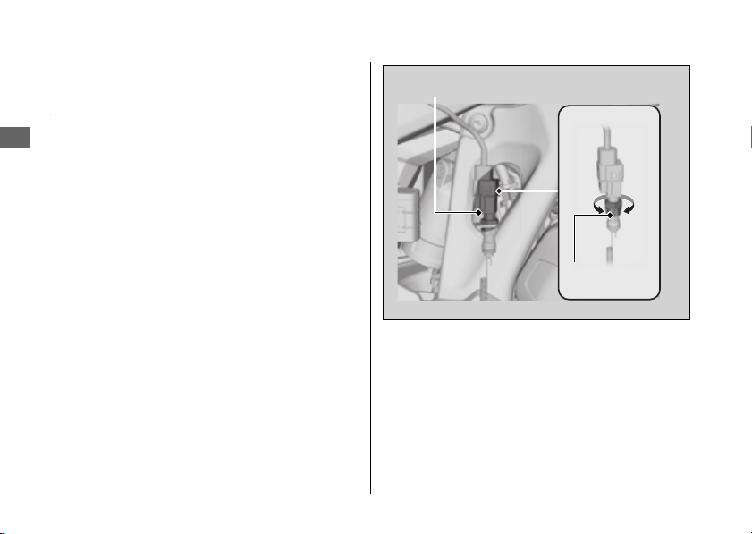
Brakes u Adjusting the Brake Light Switch
284
Maintenance
Adjusting the Brake Light
Switch
Check the operation of the brake light switch.
Hold the brake light switch and turn the
adjusting nut in the direction A if the switch
operates too late, or turn the nut in the
direction B if the switch operates too soon.
Brake light switch
Adjusting
nut
BA
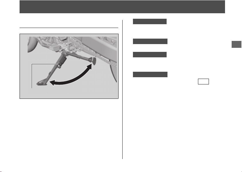
285
Maintenance
Side Stand
Checking the Side Stand
1.
Check that the side stand operates
smoothly. If the side stand is stiff or
squeaky, clean the pivot area and lubricate
the pivot bolt with clean grease.
2.
Check the spring for damage or loss of
tension.
3.
Sit on the vehicle, shift the transmission to
Neutral, and raise the side stand.
Sit on the vehicle and raise the side stand.
4.
Start the engine, pull the clutch lever in,
and shift the transmission into gear.
Start the engine and press the side of
N-D switch to switch the transmission into
D mode.
5.
Lower the side stand all the way. The
engine should stop as you lower the side
stand. If the engine doesn't stop, have your
vehicle inspected by your dealer.
Side stand spring
CRF1100A/A4
CRF1100D/D4
CRF1100A/A4
CRF1100D/D4
D-S
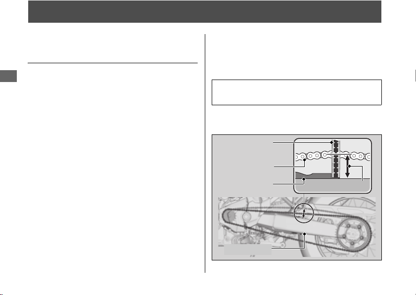
286
Maintenance
Drive Chain
Inspecting the Drive Chain
Slack
Check the drive chain slack at several points
along the chain. If the slack is not constant at
all points, some links may be kinked and
binding.
Have the chain inspected by your dealer.
1.
Shift the transmission to Neutral. Stop the
engine.
2.
Place your vehicle on its side stand on a
firm, level surface.
3.
Pull the upper half of the drive chain up
and check the chain slack between the
drive chain and swing-arm at the end of
the drive chain slider.
u Do not ride your vehicle if the slack
exceeds 2 3/8 in (60 mm).
Drive chain slack:
1 7/8 - 2 1/16 in (48 - 53 mm)
Drive chain
Drive chain
slider
Swing-arm
Drive chain slack
Ruler


288
Maintenance
Wheels
Wheels Rims & Spokes
Keeping the wheels true (round) and
maintaining correct spoke tension is critical to
safe vehicle operation.
Excessively loose spokes may result in
instability at high speeds and possible loss of
control.
It is not necessary to remove the wheels to
perform the recommended service in the
Maintenance Schedule. However, information
for wheel removal is provided for emergency
situations.
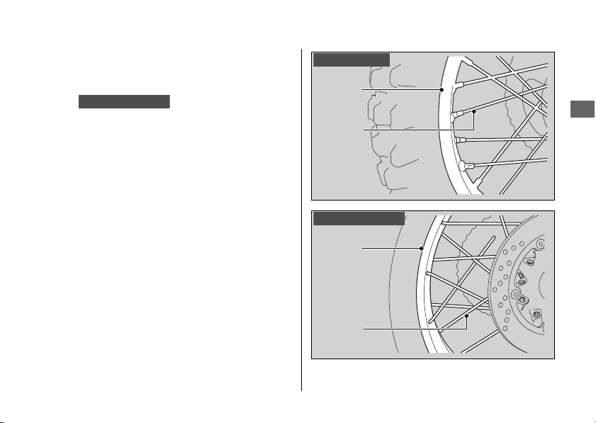
Wheels u Wheels Rims & Spokes
289
Maintenance
1.
Inspect the wheel rims and spokes for
damage.
2.
Tighten any loose spokes.
u
Use the ballpoint hexagon wrench with a
length of 5.5 in (140 mm) or more.
3.
Rotate the wheel slowly to see if it appears
to “wobble.” If it does, the rim is out of
round or not “true.” If the wobble is
noticeable, see your dealer for inspection.
CRF1100A4/D4
Wheel
rim
Spoke
CRF1100A/D
Wheel
rim
Spoke
CRF1100A4/D4
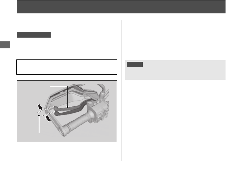
290
Maintenance
Clutch
Checking the Clutch
#
Checking the Clutch Lever Freeplay
Check the clutch lever freeplay.
Check the clutch cable for kinks or signs of
wear. If necessary have it replaced by your
dealer.
Lubricate the clutch cable with a commercially
available cable lubricant to prevent premature
wear and corrosion.
Freeplay at the clutch lever:
3/8 - 13/16 in (10 - 20 mm)
CRF1100A/A4
Clutch lever
Freeplay
NOTICE
Improper freeplay adjustment can cause premature clutch
wear.
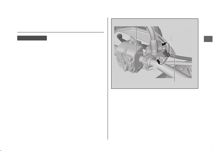
Clutch u Adjusting the Clutch Lever Freeplay
291
Continued
Maintenance
Adjusting the Clutch Lever
Freeplay
#
Upper Adjustment
Attempt adjustment with the upper clutch
cable adjuster first.
1.
Loosen the upper lock nut.
2.
Turn the upper clutch cable adjuster until
the freeplay is 3/8 - 13/16 in (10 - 20 mm).
3.
Tighten the upper lock nut and check the
freeplay again.
#
Lower Adjustment
If the upper clutch cable adjuster is threaded
out near its limit, or the correct freeplay
cannot be obtained, attempt adjustment with
the lower clutch cable adjusting nut.
CRF1100A/A4
Upper clutch cable adjuster
Upper lock nut
+
–
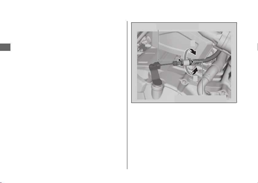
Clutch u Adjusting the Clutch Lever Freeplay
292
Maintenance
1.
Loosen the upper lock nut and turn the
upper clutch cable adjuster all the way in
(to provide maximum freeplay). Tighten
the upper lock nut.
2.
Loosen the lower lock nut.
3.
Turn the lower clutch cable adjusting nut
until the clutch lever freeplay is 3/8 - 13/16
in (10 - 20 mm).
4.
Tighten the lower lock nut and check the
clutch lever freeplay.
5.
Start the engine, pull the clutch lever in,
and shift into gear. Make sure the engine
does not stall and the vehicle does not
creep. Gradually release the clutch lever
and open the throttle. Your vehicle should
move smoothly and accelerate gradually.
If proper adjustment cannot be obtained or
the clutch does not work correctly, see your
dealer.
Lower lock nut
Lower adjusting nut
+
–
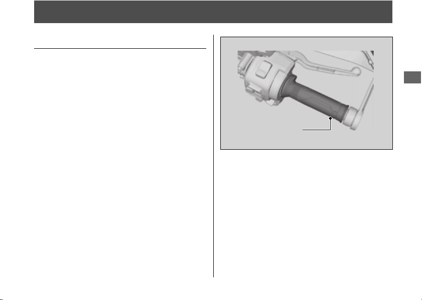
293
Maintenance
Throttle
Checking the Throttle
With the engine off, check that the throttle
rotates smoothly from fully closed to fully
open. If the throttle does not move smoothly,
close automatically, have the vehicle
inspected by your dealer.
Throttle
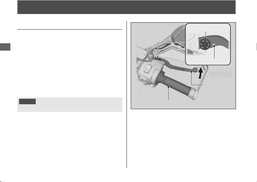
294
Maintenance
Other Adjustments
Adjusting the Brake Lever
You can adjust the distance between the tip of
the brake lever and handle grip.
#
Adjustment method
Turn the adjuster until the numbers align with
the index mark while pushing the lever
forward in the desired position.
After adjustment, check that the lever
operates correctly before riding.
NOTICE
Do not turn the adjuster beyond its natural limit.
Adjuster
Index mark
Forward
Brake lever
Handle grip
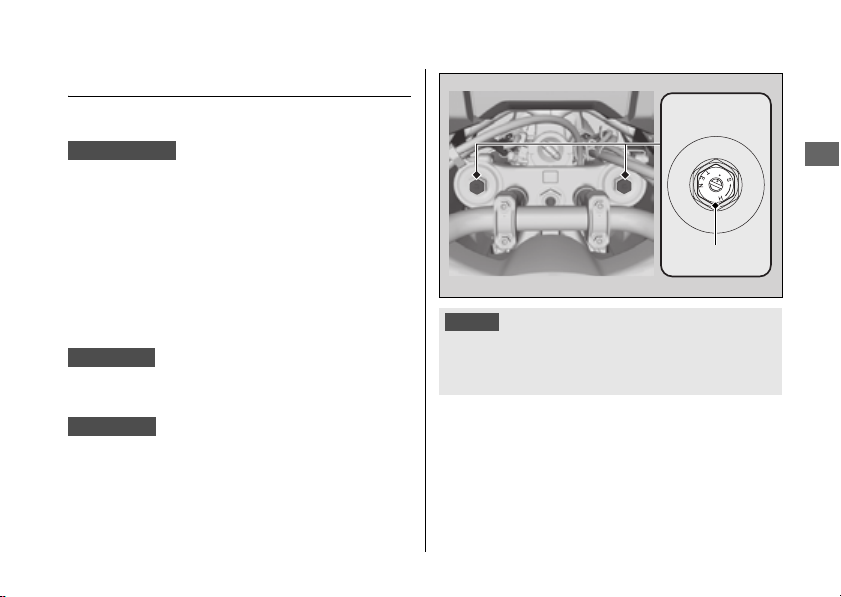
Other Adjustments u Adjusting the Front Suspension
295
Continued
Maintenance
Adjusting the Front Suspension
#
Spring Preload
You can adjust the spring preload by the
adjuster to suit the load or the road surface.
Turn the adjuster using a suitable box end
wrench.
The spring preload adjuster has 15 turns.Turn
clockwise to increase spring preload (hard), or
turn counterclockwise to decrease spring
preload (soft).
The standard position is the 2 turns from the
full soft position.
The standard position is the 5 turns from the
full soft position.
CRF1100A/D
CRF1100A
CRF1100D
NOTICE
Do not turn the adjuster beyond its limits.
Adjust both left and right forks to the same spring
preload.
Adjuster
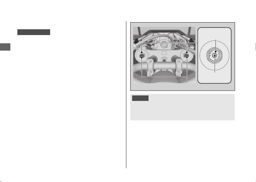
Other Adjustments u Adjusting the Front Suspension
296
Maintenance
#
Rebound Damping
You can adjust the rebound damping by the
adjuster to suit the load or the road surface.
Turn the adjuster using the Standard/Phillips
screwdriver provided on the underside of the
rear seat.
2 P. 242
The rebound damping adjuster has 3 turns or
more.
Turn clockwise to increase rebound damping
(hard), or turn counterclockwise to decrease
rebound damping (soft).
The standard position is 2 3/4 turns from the
maximum setting so that the punch mark on
the adjuster aligns with the reference punch
mark.
CRF1100A/D
NOTICE
Do not turn the adjuster beyond its limits.
Adjust both left and right forks to the same rebound
damping.
Adjusters
Reference
punch mark
Punch mark
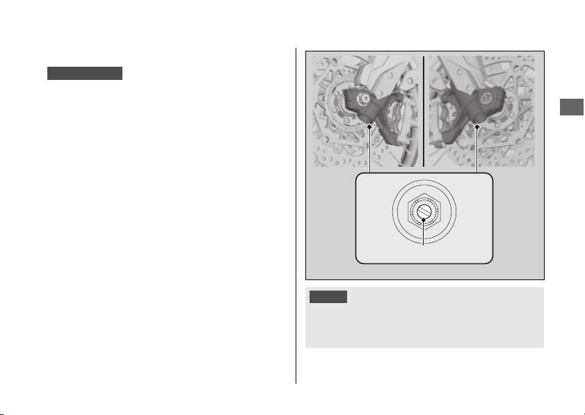
Other Adjustments u Adjusting the Front Suspension
297
Continued
Maintenance
#
Compression Damping
You can adjust the compression damping by the
adjuster to suit the load or the road surface.
Turn the adjuster using the Standard/Phillips
screwdriver provided on the underside of the
rear seat. 2 P. 242
The compression damping adjuster has 12
position or more.
Turn clockwise to increase compression
damping (hard), or turn counterclockwise to
decrease compression damping (soft).
The standard position is 9 clicks from the
maximum setting.
CRF1100A/D
NOTICE
Do not turn the adjuster beyond its limits.
Adjust both left and right forks to the same compression
damping.
Adjuster

Other Adjustments u Adjusting the Front Suspension
298
Maintenance
#
Damping
● When the riding mode is changed, front
suspension damping is automatically
selected to a setting corresponding to the
riding mode.
2 P. 145
● You can change the [S] [Overall] and [Front]
on the [USER 1 MODE] and [USER 2 MODE]
of the riding mode.
2 P. 75
● Available setting range:
[Overall]: [H] Hard / [M] Medium / [S] Soft
/ [O] Off Road
[Front]: [-]/[Medium]/[+]
● Default:
[Overall]
[USER 1 MODE]: [M] Medium
[USER 2 MODE]: [S] Soft
[Front]: [Medium]
CRF1100A4/D4
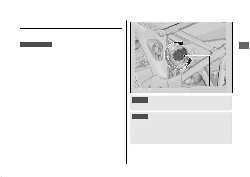
Other Adjustments u Adjusting the Rear Suspension
299
Continued
Maintenance
Adjusting the Rear Suspension
#
Spring Preload
You can adjust the spring preload by the
adjuster knob to suit the load or the road
surface. The spring preload adjuster has 35
position or more. Turn the clockwise to increase
spring preload (high), or turn counterclockwise
to decrease spring preload (low).
Turn the adjuster counterclockwise (low) until
it will no longer turn (lightly seat). Turn the
adjuster clockwise (high) until it clicks. This
click is position 0.
The standard position is 7 clicks from the
minimum setting.
CRF1100A/D
NOTICE
Do not turn the adjuster beyond its limits.
NOTICE
The rear shock absorber damper unit contains high
pressure nitrogen gas. Do not attempt to disassemble,
service, or improperly dispose of the damper. See your
dealer.
Adjuster knob
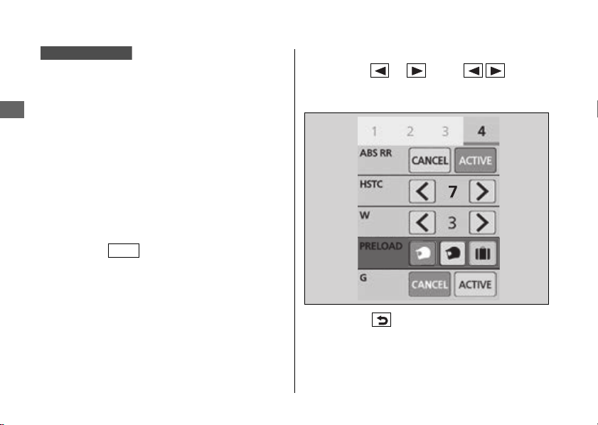
Other Adjustments u Adjusting the Rear Suspension
300
Maintenance
The electrically adjustable suspension allows
the preload of the rear suspension to be
adjusted in four levels according to riding and
load conditions.
The rear suspension spring preload
adjustment can be changed only when your
vehicle is stopped.
1.
Stop the vehicle.
2.
Select the gold image display. 2 P. 79
3.
Select page 4. 2 P. 43
4.
Press the switch.
5.
Select [PRELOAD].
6.
Push the or of the sel left/
right switch until the desired value is
displayed.
7.
Press the back switch.
You can also perform the above settings by
using the touch screen.
CRF1100A4/D4
ENT
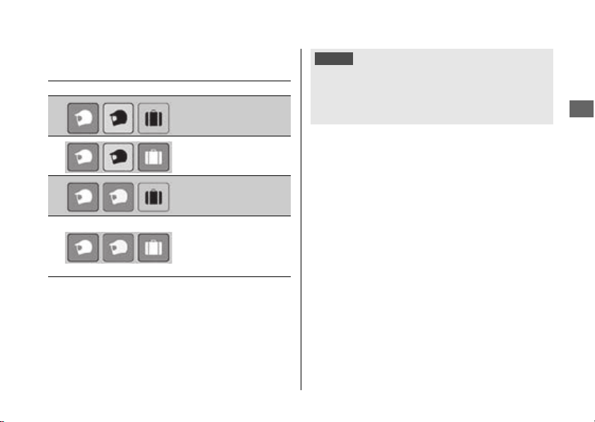
Other Adjustments u Adjusting the Rear Suspension
301
Continued
Maintenance
The rear suspension adjustment provides the
following settings.
Default: Rider only
● You can change the [PRELOAD] [Preload]
on the [USER 1 MODE] and [USER 2 MODE]
of the riding mode.
2 P. 75
Status icon Riding condition
Rider only
(Minimum preload)
Rider and luggage
Rider and
passenger
Rider, passenger
and luggage
(Maximum
preload)
NOTICE
The rear shock absorber damper unit contains high
pressure nitrogen gas. Do not attempt to disassemble,
service, or improperly dispose of the damper. See your
dealer.

Other Adjustments u Adjusting the Rear Suspension
302
Maintenance
#
Rebound Damping
You can adjust the rebound damping by the
adjuster to suit the load or the road surface.
Turn the adjuster using the Standard/Phillips
screwdriver provided on the underside of the
rear seat.
2 P. 242
Turn clockwise to increase rebound damping
(hard), or turn counterclockwise to decrease
rebound damping (soft).
The standard position is 8 clicks from the
maximum setting so that the punch mark on the
adjuster aligns with the reference punch mark.
CRF1100A/D
NOTICE
Do not turn the adjuster beyond its limits.
NOTICE
The rear shock absorber damper unit contains high
pressure nitrogen gas. Do not attempt to disassemble,
service, or improperly dispose of the damper. See your
dealer.
Reference
punch mark
Punch mark
Adjuster
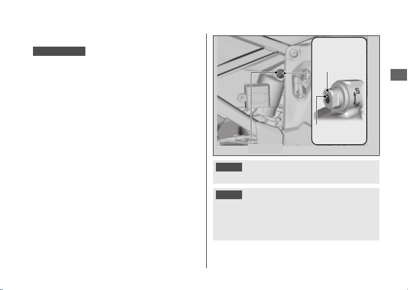
Other Adjustments u Adjusting the Rear Suspension
303
Continued
Maintenance
#
Compression Damping
You can adjust the compression damping by
the adjuster to suit the load or the road
surface.
Turn the adjuster using the Standard/Phillips
screwdriver provided on the underside of the
rear seat.
2 P. 242
Turn clockwise to increase compression
damping (hard), or turn counterclockwise to
decrease compression damping (soft).
The standard position is 12 clicks from the
maximum setting so that the punch mark on the
adjuster aligns with the reference punch mark.
CRF1100A/D
NOTICE
Do not turn the adjuster beyond its limits.
NOTICE
The rear shock absorber damper unit contains high
pressure nitrogen gas. Do not attempt to disassemble,
service, or improperly dispose of the damper. See your
dealer.
Adjuster
Reference
punch
mark
Punch mark

Other Adjustments u Adjusting the Rear Suspension
304
Maintenance
#
Damping
● When the riding mode is changed, rear
suspension damping is automatically
selected to a setting corresponding to the
riding mode.
2 P. 145
● You can change the [S] [Overall] and [Rear]
on the [USER 1 MODE] and [USER 2 MODE]
of the riding mode.
2 P. 75
● Available setting range:
[Overall]: [H] Hard / [M] Medium / [S] Soft
/ [O] Off Road
[Rear]: [-]/[Medium]/[+]
● Default:
[Overall]
[USER 1 MODE]: [M] Medium
[USER 2 MODE]: [S] Soft
[Rear]: [Medium]
CRF1100A4/D4
NOTICE
The rear shock absorber damper unit contains high
pressure nitrogen gas. Do not attempt to disassemble,
service, or improperly dispose of the damper. See your
dealer.

Other Adjustments u Adjusting the Windscreen Height
305
Continued
Maintenance
Adjusting the Windscreen
Height
You can adjust the windscreen height 1 of 5
positions.
Windscreen height indicator shows the
windscreen height.
The standard position is 1.
u Do not adjust the windscreen while riding.
1.
Push the right and left lock levers to unlock
the screen.
2.
Continue to push the right and left lock
levers, move the right and left lock levers
upward or downward to raise or lower the
windscreen.
3.
Release the right and left lock levers at the
desired position while checking height the
indicator.
u Make sure that the windscreen is locked
securely by slightly moving the right and
left lock levers up or down.
CRF1100A4/D4
Windscreen
Left lock
lever
Right lock
lever
Slider
123
4
5
Windscreen
height
indicator

Other Adjustments u Adjusting the Windscreen Height
306
Maintenance
If the windscreen does not move smoothly,
clean the sliders using a sponge or a soft towel
with neutral detergent to remove dust.
u Do not apply a lubricant to the sliders.
If the windscreen does not move smoothly
after cleaning the sliders, have your vehicle
inspected by your dealer.

Troubleshooting
Engine Will Not Start ................................P. 308
Overheating (Segment H flashes in coolant
temperature gauge) ................................P. 309
Warning Indicators On or Flashing .........P. 310
Low Oil Pressure Indicator...............................P. 310
PGM-FI (Programmed Fuel Injection) Malfunction
Indicator Lamp (MIL).......................................P. 310
ABS (Anti-lock Brake System) Indicator........P. 311
Torque Control Indicator .................................P. 312
If the “–” Indicator is Blinking in the Gear
Position Window While Riding ..............P. 313
Other Warning Indications.......................P. 314
Fuel Gauge Failure Indication......................... P. 314
Coolant Temperature Gauge Failure
Indication........................................................... P. 315
Handle Grip Heater Failure Indication.......... P. 315
Tire Puncture............................................. P. 316
Audio System Trouble.............................. P. 318
Electrical Trouble ...................................... P. 333
Battery Goes Dead............................................ P. 333
Burned-out Light Bulb...................................... P. 333
Blown Fuse.......................................................... P. 334

308
Troubleshooting
Engine Will Not Start
Starter Motor Operates But
Engine Does Not Start
Check the following items:
● Check the correct engine starting sequence.
2 P. 218
● Check that there is gasoline in the fuel tank.
● Check if the PGM-FI malfunction indicator
lamp (MIL) is on.
u If the indicator lamp is on, contact your
dealer as soon as possible.
Starter Motor Does Not
Operate
Check the following items:
● Check the correct engine starting sequence.
2 P. 218
● Make sure engine stop switch is in the
(Run) position.
2 P. 115
● Check for a blown fuse. 2 P. 334
● Check for a loose battery connection
(2 P. 267) or battery terminal corrosion
(
2 P. 256).
● Check the condition of the battery. 2 P. 333
If the problem continues, have your vehicle
inspected by your dealer.

309
Troubleshooting
Overheating (Segment H flashes in coolant temperature gauge)
The engine is overheating when the following
occurs:
● All segments turn red and the segment H
flashes in the coolant temperature gauge.
● Acceleration becomes sluggish.
If this occurs, pull safely to the side of the road
and perform the following procedure.
Extended fast idling may cause all segments
turn red and the segment H to flash.
1.
Stop the engine using the ignition switch,
and then turn the ignition switch to the ON
position.
2.
Check that the radiator fan is operating,
and then turn the ignition switch to the OFF
position.
Suspect a fault. Do not start the engine.
Transport your vehicle to your dealer.
Allow the engine to cool with the ignition
switch in the OFF position.
3.
After the engine has cooled, inspect the
radiator hose and check if there is a leak.
2 P. 279
Do not start the engine. Transport your
vehicle to your dealer.
4.
Check the coolant level in the reserve tank.
2 P. 279
u
Add coolant as necessary.
5.
If 1-4 check normal, you may continue
riding, but closely monitor the temperature
gauge.
NOTICE
Continuing to ride with an overheated engine can cause
serious damage to the engine.
If the fan is not operating:
If the fan is operating:
If there is a leak:

310
Troubleshooting
Warning Indicators On or Flashing
Low Oil Pressure Indicator
If the low oil pressure indicator comes on, pull
safely to the side of the road and stop the
engine.
1.
Check the engine oil level, and add oil as
necessary. 2 P. 277, 2 P. 278
2.
Start the engine.
u
Only continue riding if the low oil pressure
indicator goes off.
Rapid acceleration may momentarily cause the
low oil pressure indicator to come on, especially
if the oil is at or near the low level.
If the low oil pressure indicator stays on when the
oil level is at the proper level, stop the engine
and contact your dealer.
If the engine oil level goes down rapidly, your
vehicle may have a leak or another serious
problem. Have your vehicle inspected by your
dealer.
PGM-FI (Programmed Fuel
Injection) Malfunction
Indicator Lamp (MIL)
If the indicator comes on while riding, you may
have a serious problem with the PGM-FI system.
Reduce speed and have your vehicle inspected
by your dealer as soon as possible.
NOTICE
Continuing to ride with low oil pressure can cause serious
damage to the engine.

Warning Indicators On or Flashing u ABS (Anti-lock Brake System) Indicator
311
Troubleshooting
ABS (Anti-lock Brake
System) Indicator
If the indicator operates in one of the
following ways, you may have a serious
problem with the ABS. Reduce your speed
and have your vehicle inspected by your
dealer as soon as possible.
● Indicator comes on or starts flashing while
riding.
● Indicator does not come on when the
ignition switch is in the ON position.
● Indicator does not go off at speeds above 6
mph (10 km/h).
If the ABS indicator stays on, your brakes will
continue to work as a conventional system,
but without the anti-locking function.
The ABS indicator may flash if you turn the
rear wheel while the rear wheel is lifted off the
ground. In this case, turn the ignition switch to
the OFF position, and then to the ON position
again. The ABS indicator will go off after your
speed reaches 19 mph (30 km/h).

Warning Indicators On or Flashing u Torque Control Indicator
312
Troubleshooting
Torque Control Indicator
If the indicator operates in one of the
following ways, you may have a serious
problem with the Torque Control. Reduce
your speed and have your vehicle inspected
by your dealer as soon as possible.
● Indicator comes and stays on (solid) while
riding.
● Indicator does not come on when the
ignition switch is turned to the ON position.
● Indicator does not go off at speeds above 3
mph (5 km/h).
Even when the Torque Control indicator is on,
your vehicle will have normal riding ability
without Torque Control function.
u When the indicator comes on while the
Torque Control is in operation, you will
have to completely close the throttle to
regain normal riding ability.
The Torque Control indicator may come on if
you rotate the rear wheel while your vehicle is
lifted off the ground. In this case, turn the
ignition switch to the OFF position, and then
to the ON position again. The Torque Control
indicator will go off after your speed reaches 3
mph (5 km/h).

313
Troubleshooting
If the “–” Indicator is Blinking in the Gear Position Window While Riding
If the “–” indicator is blinking while riding, you
may have a serious problem with the Dual
Clutch Transmission system.
Park your vehicle in a safe place and have your
vehicle inspected by a dealer immediately.
It may be possible to ride your vehicle by
following the steps below.
1.
Turn the ignition switch to the OFF
position.
2.
Turn the ignition switch to the ON position
and start the engine.
Turn the ignition switch to the OFF position
and move the vehicle back and forth slightly
(to disengage the gears).
Turn the ignition switch to the ON position
again and start the engine.
Start the engine while applying the brake lever
or pressing the brake pedal.
When a gear position is shown in the gear
position indicator, you can ride in that gear.
Take your vehicle to your dealer riding at a
safe speed.
Damage is preventing you from riding. Have
your vehicle inspected by your dealer
immediately.
CRF1100D/D4
If you cannot start the engine:
If you still cannot start the engine:
If you can shift from N to D mode:
If you can't shift from N to D mode and the “–”
indicator is blinking:
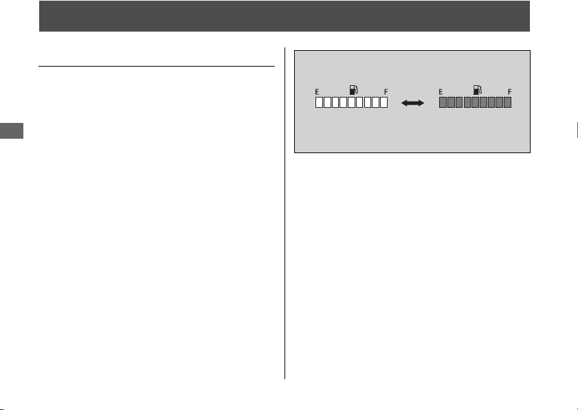
314
Troubleshooting
Other Warning Indications
Fuel Gauge Failure Indication
If the fuel system has an error, all segments
will blink as shown in the illustration.
If these occur, see your dealer as soon as
possible.
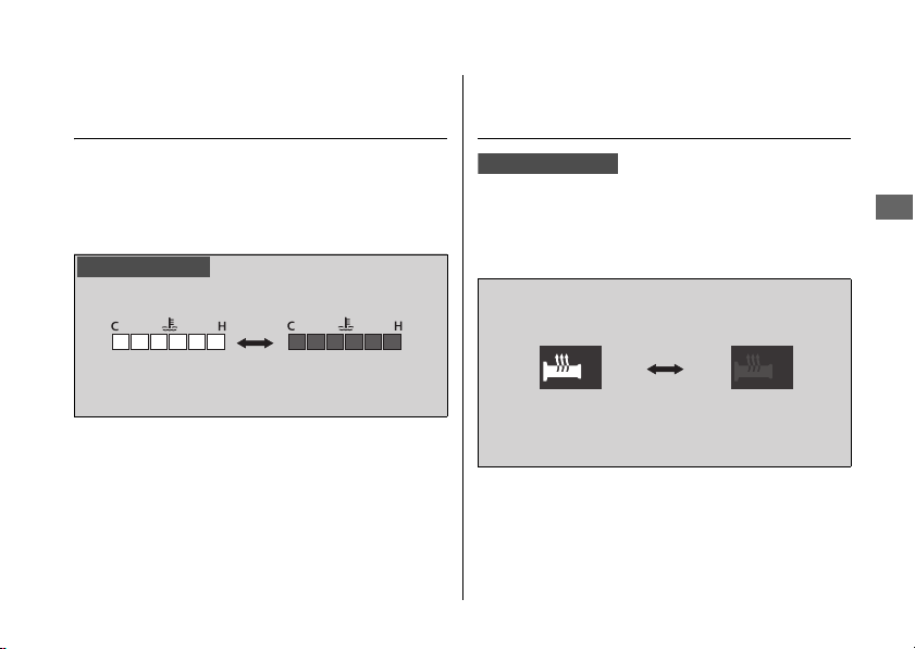
Other Warning Indications u Coolant Temperature Gauge Failure Indication
315
Troubleshooting
Coolant Temperature Gauge
Failure Indication
If the cooling system has an error, all
segments will blink as shown in the illustration.
If this occurs, see your dealer as soon as
possible.
Handle Grip Heater Failure
Indication
If the handle grip heater system has an error,
the handle grip heater status icon will blink. If
these occur, see your dealer as soon as
possible.
Gold image only
CRF1100A4/D4

316
Troubleshooting
Tire Puncture
Repairing a puncture or removing a wheel
requires special tools and technical expertise.
We recommend you have this type of service
performed by your dealer.
After an emergency repair, always have the
tire inspected/replaced by your dealer.
Emergency Repair Using a Tire
Repair Kit
If your tire has a minor puncture, you can
make an emergency repair using a tubeless
tire repair kit.
Follow the instructions provided with the
emergency tire repair kit.
Riding your vehicle with a temporary tire
repair is very risky. Do not exceed 30 mph (50
km/h). Have the tire replaced by your dealer
as soon as possible.
CRF1100A4/D4
3
WARNING
Riding your vehicle with a temporary tire
repair can be risky. If the temporary
repair fails, you can crash and be
seriously injured or killed.
If you must ride with a temporary tire
repair, ride slowly and carefully and do
not exceed 30 mph (50 km/h) until the
tire is replaced.

Tire Puncture u Tube Repair and Replacement
317
Troubleshooting
Tube Repair and Replacement
If a tube is punctured or damaged, you should
replace it as soon as possible. A tube that is
repaired may not have the same reliability as a
new one, and it may fail while you are riding.
If you need to make a temporary repair by
patching a tube or using an aerosol sealant,
ride cautiously at reduced speed and have the
tube replaced before you ride again.
Anytime a tube is replaced, the tire should be
carefully inspected as described.
CRF1100A/D
3
WARNING
Riding your vehicle with a temporary tire
or tube repair can be risky. If the
temporary repair fails, you can crash and
be seriously injured or killed.
If you must ride with a temporary tire or
tube repair, ride slowly and carefully and
do not exceed 30 mph (50 km/h) until
the tire or tube is replaced.
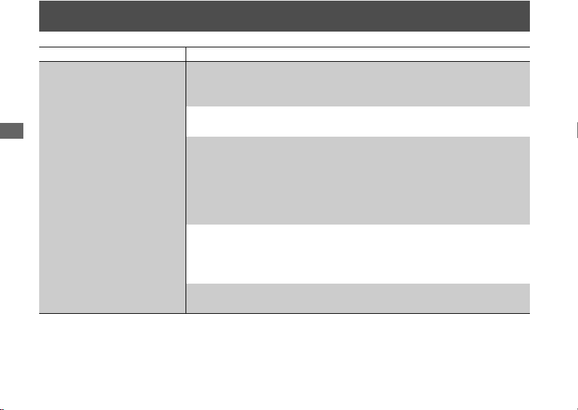
318
Troubleshooting
Audio System Trouble
Symptom Cause/remedy
Unable to pair Bluetooth
®
device
Some Bluetooth
®
devices and application software you use may
be incompatible with the audio system and/or the operable
functions may be limited.
Check that the audio system and Bluetooth
®
device are both in
pairing mode.
2 P. 157 2 P. 162
The audio system may not be properly connected when another
Bluetooth
®
device is being paired at the same time. Check your
surroundings to make sure no other device being paired is
present before re-pairing. Presence of a Bluetooth
®
device in the
vicinity sometimes affects the pairing due to radio wave
interference, etc.
When connecting a Bluetooth
®
device, make sure no other
Bluetooth
®
device readied for pairing is present. Presence of a
Bluetooth
®
device in the vicinity sometimes affects the pairing
due to radio wave interference, etc.
When you repeatedly fail in pairing, delete the paired device once,
then try pairing again.
2 P. 157 2 P. 162
Audio System Trouble
319
Continued
Troubleshooting
Symptom Cause/remedy
Unable to connect
Bluetooth
®
device
Depending on the Bluetooth
®
device and application software
you use, it may take some time for the audio system to connect to
a device and to start playing an audio file.
The connection may be temporarily disconnected when starting
the engine, which is normal and not a malfunction. The
Bluetooth
®
device will be reconnected after the engine is started.
Check that your Bluetooth
®
device has been paired. Refer to the
instruction manual of your Bluetooth
®
device and check that your
Bluetooth
®
device is in connectable state.
Audio System Trouble
320
Troubleshooting
Symptom Cause/remedy
Unable to connect
Bluetooth
®
phone device
Some Bluetooth
®
devices and application software you use may
not connect automatically. For connecting, follow the instructions
in the instruction manual of your Bluetooth
®
device.
The Bluetooth
®
devices that can be connected at the same time
are limited to one Bluetooth
®
device and two Bluetooth
®
headsets.
If the problem continues after the above-described inspection,
delete the paired device once, then try pairing again.
2 P. 157
2 P. 162
The Bluetooth
®
connection cannot be established while
launching Apple CarPlay. Quit Apple CarPlay, then try pairing
again.
2 P. 195 2 P. 157
While connected to Apple CarPlay, Bluetooth
®
function is
disabled.

Audio System Trouble
321
Continued
Troubleshooting
Symptom Cause/remedy
Connected, but does not
play.
Some Bluetooth
®
devices and application software you use may
be incompatible with the audio system and/or audio files may not
be played properly. Check the recommended specifications.
2 P. 156
Depending on the Bluetooth
®
device and application software
you use, an audio file may not play automatically. For playing,
follow the instructions in the instruction manual of your
Bluetooth
®
device.
Depending on the Bluetooth
®
device and application software
you use, an audio file may not play normally after receiving a
telephone call, etc. Check that your Bluetooth
®
device is in
playable state.
Takes some time to start
playing after turning the
power on or changing the
audio mode.
Right after the power is turned on or the audio mode is changed,
the audio system may take some time to connect to an audio
device and to start playing an audio file. Also, the audio system
may not allow any audio control operation while preparing to play
an audio file.
Audio System Trouble
322
Troubleshooting
Symptom Cause/remedy
Sounds skip
Noises mix
Presence of another Bluetooth
®
device or a device that emits
electromagnetic waves such as communication equipment in the
vicinity sometimes affects the communication.
Due to the characteristics of Bluetooth
®
, though in rare cases, the
system operation may become unstable. When it remains
unstable, turn off the power to the audio system or the device
being used, and then turn it on again.
The storage location of the Bluetooth
®
device sometimes affects
the audio system and communication. When sounds skip or
noises mix, change the location of the device. For example, when
the device is kept in a pocket of clothing sandwiched in between
the rider and passenger, the communication may be affected.
Also, weather, buildings in the vicinity, road conditions, etc. can
sometimes affect the communication.

Audio System Trouble
323
Continued
Troubleshooting
Symptom Cause/remedy
Sounds skip
Noises mix
Depending on the Bluetooth
®
device and application software
you use, an audio file may not play normally after receiving a
telephone call, etc. Turn off the power to the audio system and
then turn it on again. If the skipping of sounds or mixing of noises
continues, check the status of your Bluetooth
®
device.
If the skipping of sounds or mixing of noises continues, delete the
paired device once, then try pairing again. 2 P. 165
Check the recommended specifications. 2 P. 156

Audio System Trouble
324
Troubleshooting
Symptom Cause/remedy
Audio volume from
headset is low/high
Adjust the volume while in the individual modes. 2 P. 93
Check the volume setting of the Bluetooth
®
audio device.
Check the volume setting of the paired headset.
No or inaccurate display
Depending on the audio device and the audio file, nothing may
be displayed or the display may be inaccurate in some cases.
Check the information on available tags.
2 P. 174
When the information in an audio file such as the artist name and
track title is in a non-compliant tag format, it may be indicated by
“ ” or no information will be shown.
Audio System Trouble
325
Continued
Troubleshooting
Symptom Cause/remedy
Bluetooth
®
handsfree
calling is not functioning
Connected Bluetooth
®
device may be an unsupported device.
Check the supported Bluetooth
®
version/profiles. 2 P. 156
When the Bluetooth
®
connection is unstable due to surrounding
conditions or radio wave conditions, the handsfree calling
functions may not be available.
To use Bluetooth
®
handsfree calling, a headset connection is
necessary. Connect a paired headset.
2 P. 162
During a call, headset
volume is low/high
Adjust the volume during a call. 2 P. 93
Passenger's headset has
no sound
Passenger headset only outputs music. Music playback is
interrupted while using the handsfree phone or Siri.
Audio System Trouble
326
Troubleshooting
Symptom Cause/remedy
Bluetooth
®
Handsfree
calling problems
Depending on the connection status, the times displayed in call
history on the vehicle side or the phone side may differ.
Depending on your mobile carrier plan, available functions may differ.
A display delay may occur depending on the number of phone
books, call history and music data etc. stored in the connected device.

Audio System Trouble
327
Continued
Troubleshooting
Symptom Cause/remedy
Apple CarPlay is not
functioning
Connected iPhone may be an unsupported model. Check the
models compatible with Apple CarPlay.
2 P. 190
Connected iPhone may be an unsupported iOS version. Update the
iPhone to the newer version.
To use Apple CarPlay, a headset connection is necessary. Connect
a paired headset.
2 P. 162
When a mobile network communication is unstable due to
surrounding conditions or signal strength conditions, Apple CarPlay
functions may not be available.
Audio System Trouble
328
Troubleshooting
Symptom Cause/remedy
Apple CarPlay is not
functioning
When the paired headset connection is broken due to headset
battery depletion or communication failure, Apple CarPlay cannot be
used until the connection is restored.
The screen will not switch to Apple CarPlay automatically, other than
when the ignition switch is turned to the OFF position with Apple
CarPlay activated.
Some USB cables may be incompatible with Apple CarPlay. Use
certified cable to connect the iPhone.
You have not agreed to enable Apple CarPlay. Reconnect the
iPhone and enable CarPlay on the disclaimer screen.
2 P. 193
Apple CarPlay setting on your iPhone may be disabled. Disconnect
iPhone and enable the Apple CarPlay setting on your iPhone.
Audio System Trouble
329
Continued
Troubleshooting
Symptom Cause/remedy
Android Auto is not
functioning
Connected Android phone may be unsupported model. Check
the compatible model with Android Auto.
2 P. 204
Connected
Android
phone may be unsupported
Android
version.
Update the
Android
phone to the newer version.
To use full function of Android Auto, a headset connection is
necessary. Connect a paired headset.
2 P. 162
When a mobile network communication is unstable due to
surrounding conditions or signal strength conditions,
Android Auto
functions may not be available.

Audio System Trouble
330
Troubleshooting
Symptom Cause/remedy
Android Auto is not
functioning
When the paired headset connection is broken due to headset
battery depletion or communication failure, go back to the Home
screen, and pair the headset connection again.
Some USB cables may be incompatible with
Android Auto
. For
Android Auto
, the USB cables should be certified by USB-IF to be
compliant with USB 2.0 Standard.
You have not agreed to enable Android Auto. Reconnect the
Android phone and enable to use Android Auto on the disclaimer
screen.
2 P. 213
Android Auto
setting on your
Android
phone may be disabled.
Disconnect
Android
phone and enable the
Android Auto
setting on
your
Android
phone.

Audio System Trouble
331
Continued
Troubleshooting
Symptom Cause/remedy
Connected, but does not
operate Apple CarPlay/
Android Auto.
You cannot operate Apple CarPlay/Android Auto by the touch
panel while the vehicle is in motion. Operate with the left
handlebar switches or park your vehicle in a safe place, then
operate.
Some functions of Apple
CarPlay/Android Auto not
available.
Some functions may be limited due to condition of mobile
network communication.
Apple CarPlay/Android
Auto screen is too dark/
bright
Selecting [Background] menu in [Settings], you can select white
mode or black mode in the navigation map or an application such
as Maps, also adjust backlight brightness by [Brightness] menu in
[Settings]
2 P. 82 2 P. 81.
Audio system cannot
operate.
Certain manual functions and settings are disabled or inoperable
while the vehicle is in motion. You cannot select a greyed-out
menu until the vehicle is stopped.
When turning the ignition
switch to the OFF and ON
position continuously.
Since the system restart takes time, it may take time until the
screen is appears.

Audio System Trouble
332
Troubleshooting
If the problem continues after the above-described inspection, have your vehicle inspected by
your dealer.
Symptom Cause/remedy
High temperature/
overcurrent protection
To protect the system, some operations may be limited
temporarily. The system automatically recovers after the cause is
solved.
Software update
The statements in this owner's manual may not match your
vehicle's Audio System after performing the software update.

333
Troubleshooting
Electrical Trouble
Battery Goes Dead
Battery charging is needed.
A battery charger recommended by your
lithium-ion (li-ion) battery manufacturer is
needed for battery charging.
Contact your dealer before charging the
battery.
Remove the battery from the vehicle before
charging.
If the battery does not recover after
recharging, contact your dealer.
Burned-out Light Bulb
All light bulbs on the vehicle are LEDs. If there
is an LED which is not turned on, see your
dealer for servicing.
NOTICE
Only use a charger recommended by your lithium-ion (li-
ion) battery manufacturer. Using a battery charger that is
not recommended can cause permanent damage to your
battery.
NOTICE
Do not jump-start, as this can damage your vehicle's
electrical system and battery.
Bump starting is not recommended.
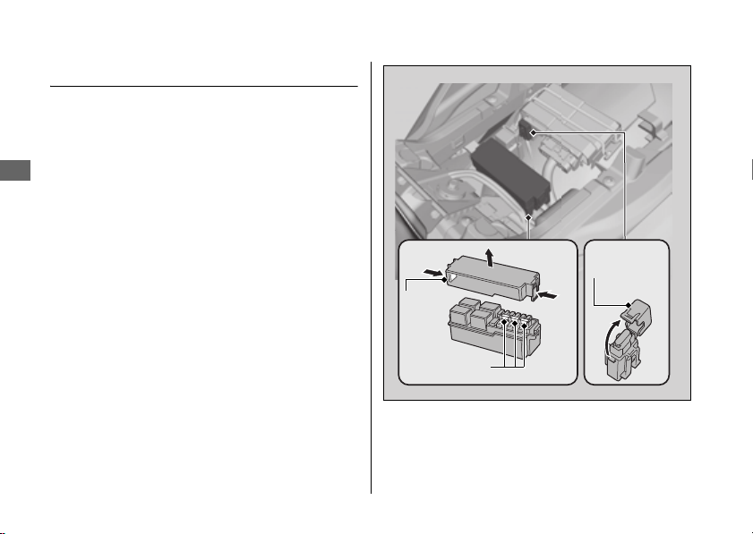
Electrical Trouble u Blown Fuse
334
Troubleshooting
Blown Fuse
Before handling fuses, see “Inspecting and
Replacing Fuses.”
2 P. 257
#
Fuse Box Fuses & ABS FSR Fuse
1.
Remove the front seat. 2 P. 270
2.
Open the fuse box covers.
3.
Pull the fuses out with the fuse puller
provided on the underside of the rear seat
(
2 P. 242) one by one check for a blown
fuse. Always replace a blown fuse with a
spare fuse of the same rating.
4.
Close the fuse box covers.
5.
Reinstall the front seat.
Spare fuses
Fuse
box
cover
Fuse box
cover
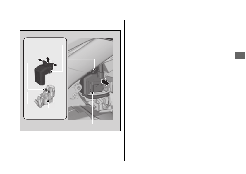
Electrical Trouble u Blown Fuse
335
Continued
Troubleshooting
#
Main Fuse & ABS Main Fuse
1.
Remove the battery box cover. 2 P. 268
2.
Pull the starter magnetic switch out.
3.
Remove the starter magnetic switch cover.
4.
Pull the main fuse and ABS main fuse out
with the fuse puller provided on the
underside of the rear seat (
2 P. 242) one by
one check for a blown fuse. Always replace
a blown fuse with a spare fuse of the same
rating.
u Spare main fuse and spare ABS main
fuse are provided in the starter magnetic
switch.
5.
Reinstall parts in the reverse order of
removal.
Starter magnetic switch
Spare
fuse
Main
fuse
Starter magnetic
switch cover
ABS main
fuse

Electrical Trouble u Blown Fuse
336
Troubleshooting
#
FI Fuse & Main 2 Fuse
1.
Remove the battery box cover. 2 P. 268
2.
Pull the FI fuse box and main 2 fuse box
suspension out.
3.
Open the fuse box cover.
4.
Pull the FI fuse and main 2 fuse out with the
fuse puller provided on the underside of
the rear seat (
2 P. 242) and check for a
blown fuse. Always replace a blown fuse
with a spare fuse of the same rating.
u Spare FI fuse is provided in the fuse box
under the front seat.
2 P. 334
u Spare main 2 fuse is provided in the
starter magnetic switch.
5.
Reinstall parts in the reverse order of
removal.
CRF1100A/A4
FI fuse
Main 2 fuse
Fuse box covers
FI fuse box and
main 2 fuse box
suspension
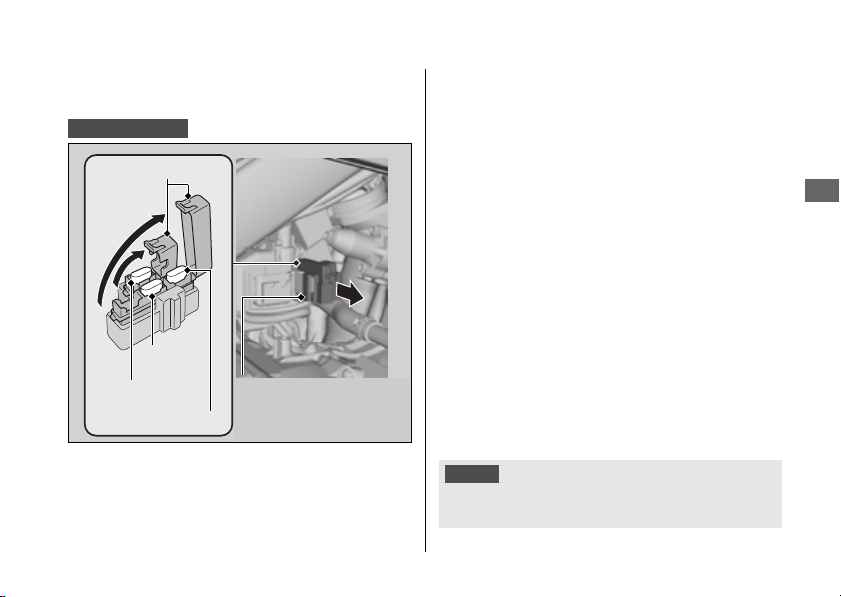
Electrical Trouble u Blown Fuse
337
Troubleshooting
#
FI Fuse & Main 2 Fuse & DCT Main
Fuse
1.
Remove the battery box cover. 2 P. 268
2.
Pull the main 2 fuse/FI main fuse box and
DCT fuse box suspension out.
3.
Open the fuse box covers.
4.
Pull the FI fuse, main 2 fuse and DCT main
fuse out with the fuse puller provided on
the underside of the rear seat (
2 P. 242)
one by one check for a blown fuse. Always
replace a blown fuse with a spare fuse of
the same rating.
u Spare FI fuse is provided in the fuse box
under the front seat.
2 P. 334
u Spare main 2 fuse and spare DCT main
fuse are provided in the starter magnetic
switch.
5.
Reinstall parts in the reverse order of
removal.
CRF1100D/D4
DCT main fuse
FI fuse
Main 2 fuse
Fuse box covers
Main 2 fuse/FI main
fuse box and DCT
fuse box suspension
NOTICE
If a fuse fails repeatedly, you likely have an electrical
problem. Have your vehicle inspected by your dealer.

Information
Service Diagnostic Recorders .................. P. 339
Keys ............................................................ P. 339
Instruments, Controls, & Other
Features.................................................... P. 340
Caring for Your Vehicle ............................ P. 345
Storing Your Vehicle................................. P. 349
Transporting Your Vehicle ....................... P. 350
You & the Environment............................ P. 351
Vehicle Identification Number ................ P. 352
Emission Control Systems ........................ P. 353
Catalytic Converter ................................... P. 357
Oxygenated Fuels...................................... P. 358
Authorized Manuals..................................P. 359
Warranty Coverage and Service ..............P. 360
Honda Contacts .........................................P. 363
Reporting Safety Defects .........................P. 365
Legal Information on Apple CarPlay/Android
Auto ...........................................................P. 368
Software Upgrades....................................P. 372

Service Diagnostic Recorders
339
Continued
Information
Service Diagnostic
Recorders
Your vehicle is equipped with service-related
devices that record information about
powertrain performance and riding conditions.
The data can be used to help technicians
diagnose, repair and maintain the vehicle. This
data may not be accessed by anyone else except
as legally required or with the permission of the
vehicle owner.
However this data may be accessed by Honda,
its authorised dealers and authorised repairers,
employees, representatives and contractors only
for the purpose of the technical diagnosis,
research and development of the vehicle.
Keys
This vehicle has two ignition keys and a key tag
with a key number and a bar code. Store the
spare key and the key tag in a safe location. To
make a duplicate key, take the spare key and the
key tag to your dealer or a locksmith.
If you lose all ignition keys and the key tag, the
ignition switch assembly will probably have to be
removed by your dealer to determine the key
number.
A metal key holder may cause damage to the area
surrounding the ignition switch.
Ignition Key
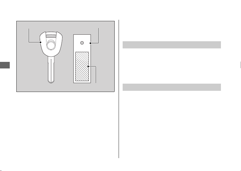
Instruments, Controls, & Other Features
340
Information
Instruments, Controls, &
Other Features
Leaving the ignition switch in the ON position
with the engine stopped will drain the battery.
Do not turn the key while riding.
Do not use the engine stop switch except in an
emergency. Doing so when riding will cause the
engine to suddenly turn off, making riding
unsafe.
If you stop the engine using the engine stop
switch, turn the ignition switch to the OFF
position. Failing to do so will drain the battery.
Ignition key Key tag
Key number and bar code
Ignition Switch
Engine Stop Switch

Instruments, Controls, & Other Features
341
Continued
Information
The display locks at 999,999 when the read-out
exceeds 999,999.
The tripmeters return to 0.0 when each read-out
exceeds 9,999.9.
1: E-Label instructions as listed below
Viewing E-Label Compliance and Regulatory
Information
1.Select the Clock
2.Select Settings > Regulatory
2: FCC 2 Part Statement
FCC Compliance
This device complies with part 15 of the FCC
Rules. Operation is subject to the following
two Conditions: (1) this device may not cause
harmful interference, and (2) this device
must accept any interference received,
including interference that may cause
undesired operation.
Odometer
Tripmeter
Audio system

Instruments, Controls, & Other Features
342
Information
This equipment has been tested and found
to comply with the limits for a Class B digital
device, pursuant to part 15 of the FCC rules.
These limits are designed to provide
reasonable protection against harmful
interference in a residential installation. This
equipment generates, uses, and can radiate
radio frequency energy and may cause
harmful interference to radio
communications if not installed and used in
accordance with the instructions. However,
there is no guarantee that interference will
not occur in a particular installation. If this
equipment does cause harmful interference
to radio or television receptions, which can
be determined by turning the equipment off
and on, the user is encouraged to try to
correct the interference by one of the
following measures:
● Reorient or relocate the receiving
antenna.
● Increase the separation between the
equipment and the receiver.
● Connect the equipment into an outlet that
is on a different circuit from the GPS
device.
● Consult the dealer or an experienced
radio/TV technician for help.
This product does not contain any user-
serviceable parts. Repairs should only be
made by an authorized Garmin service
center. Unauthorized repairs or
modifications could result in permanent
damage to the equipment, and void your
warranty and your authority to operate this
device under Part 15 regulations.
3: ISED compliance statements
Innovation, Science and Economic
Development Canada Compliance

Instruments, Controls, & Other Features
343
Continued
Information
This device complies with Innovation, Science
and Economic Development Canada license-
exempt RSS standard(s). Operation is subject to
the following two conditions: (1) this device may
not cause interference, and (2) this device must
accept any interference, including interference
that may cause undesired operation of the
device.
Innovation, Sciences et Développement
économique Canada - Conformité
Cet appareil est conforme aux normes RSS sans
licence du ministére Innovation, Sciences et
Développement économique Canada. Son
fonctionnement est soumis aux deux conditions
suivantes:
(1) cet périphérique ne doit pas causer
d'interférences, et (2) doit accepter toute
interférence, y compris les interférences pouvant
entraîner un fonctionnement indésirable de
l'appareil.
The owner’s manual, registration, and insurance
information can be stored in the plastic
document bag located on the underside of the
front seat.
2 P. 241
IMU (Inertia Measurement Unit) sensor
automatically stops the engine and fuel pump if
the vehicle falls over. To reset the IMU, you must
turn the ignition switch to the OFF position and
back to the ON position before the engine can
be restarted.
If a failure of the IMU is detected, the engine and
fuel pump will not stop automatically when the
vehicle falls over.
Document Bag
Ignition Cut-off System
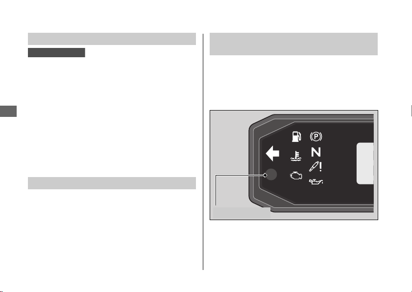
Instruments, Controls, & Other Features
344
Information
The assist-slipper clutch system helps to prevent
the rear tire from locking up when the
deceleration of your vehicle produces a strong
engine braking effect. It also makes the clutch
lever operation feel lighter.
Use only MA classification engine oil for your
vehicle. Using engine oil other than MA
classification oil could result in damage to the
assist-slipper clutch system.
This model is equipped with a Throttle by Wire
System.
Do not put magnetized items or items
susceptible to magnetic interference near the
right handlebar switches.
Ambient brightness is detected by the
photosensor.
Do not damage or cover the photosensor.
Otherwise, the automatic brightness control and
background control may not work properly.
Assist-slipper Clutch System
Throttle by Wire System
CRF1100A/A4
Automatic Brightness Control and
Background Control
Photosensor

Caring for Your Vehicle
345
Continued
Information
Caring for Your Vehicle
Frequent cleaning and polishing is important to
ensure the life of your Honda. A clean vehicle
makes it easier to spot potential problems.
In particular, seawater and salts used to prevent
ice on roads promote the formation of corrosion.
Always wash your vehicle thoroughly after riding
on coastal or treated roads.
Allow the engine, muffler, brakes, and other
high-temperature parts to cool before washing.
1.
Rinse your vehicle thoroughly using a low
pressure garden hose to remove loose dirt.
2.
If necessary, use a sponge or a soft towel with
mild cleaner to remove road grime.
u Clean the windscreen, headlight lens,
panels, and other plastic components with
extra care to avoid scratching them. Avoid
directing water into the air cleaner, muffler,
and electrical parts.
3.
Thoroughly rinse your vehicle with plenty of
clean water and dry with a soft, clean cloth.
4.
After the vehicle dries, lubricate any moving
parts.
u Make sure that no lubricant spills onto the
brakes or tires. Brake discs, pads, drum or
shoes contaminated with oil will suffer
greatly reduced braking effectiveness and
can lead to a crash.
5.
Lubricate the drive chain immediately after
washing and drying the vehicle.
6.
Apply a coat of wax to prevent corrosion.
u Avoid products that contain harsh
detergents or chemical solvents. These can
damage the metal, paint, and plastic on
your vehicle.
Keep the wax clear of the tires and brakes.
u If your vehicle has any matte painted parts,
do not apply a coat of wax to the matte
painted surface.
Washing

Caring for Your Vehicle
346
Information
#
Washing Precautions
Follow these guidelines when washing:
● Do not use high-pressure washers:
u High-pressure water cleaners can damage
moving parts and electrical parts, rendering
them inoperable.
u Water in the air intake can be drawn into
the throttle body and/or enter the air
cleaner.
● Do not direct water at the muffler:
u Water in the muffler can prevent starting
and causes rust in the muffler.
● Dry the brakes:
u Water adversely affects braking
effectiveness. After washing, apply the
brakes intermittently at low speed to help
dry them.
● Do not direct water under the seat:
u Water in the under seat compartment can
damage your documents and other
belongings.
● Do not direct water at the air cleaner:
u Water in the air cleaner can prevent the
engine from starting.
● Do not direct water near the headlight:
u The headlight's inside lens may fog
temporarily after washing or while riding in
the rain. This does not impact the headlight
function.
However, if you see a large amount of
water or ice accumulated inside the
lens(es), have your vehicle inspected by
your dealer.
● Do not use wax or polishing compounds on
matte painted surfaces:
u Use a soft cloth or sponge, plenty of water,
and a mild detergent to clean matte
painted surfaces. Dry with a soft clean cloth.

Caring for Your Vehicle
347
Continued
Information
Aluminum will corrode from contact with dirt,
mud, or road salt. Clean aluminum parts
regularly and follow these guidelines to avoid
scratches:
● Do not use stiff brushes, steel wool, or cleaners
containing abrasives.
● Avoid riding over or scraping against curbs.
Follow these guidelines to prevent scratches and
blemishes:
● Wash gently using a soft sponge and plenty of
water.
● To remove stubborn stains, use diluted
detergent and rinse thoroughly with plenty of
water.
● Avoid getting gasoline, brake fluid, or
detergents on the instruments, panels, or
headlight.
Aluminum Components Panels

Caring for Your Vehicle
348
Information
Using plenty of water, clean the windscreen with
a soft cloth or sponge. (Avoid using detergents
or any kind of chemical cleaner on the
windscreen.) Dry with a soft, clean cloth.
For a dirtier windscreen, use a diluted neutral
detergent with a sponge and plenty of water.
Make sure to wash off all the detergent.
(Detergent residue may cause windscreen
cracks.)
Replace the windscreen if scratches cannot be
removed and they obstruct clear vision.
Take care to keep battery electrolyte, brake fluid,
or other chemical solvents off the windscreen
and screen garnish. They will damage the plastic.
The exhaust pipe and muffler are stainless steel but
may become stained by mud or dust.
To remove mud or dust, use a wet sponge and a liquid
kitchen abrasive, then rinse well with clean water. Dry
with chamois or a soft towel.
If necessary, remove heat stains by using a
commercially available fine texture compound. Then,
rinse by the same manner as removing mud or dust.
When the exhaust pipe and muffler are painted, do
not use a commercially available abrasive kitchen
cleaning compound. Use a neutral detergent to clean
the painted surface on the exhaust pipe and muffler. If
you are not sure if your exhaust pipe and muffler are
painted, contact your dealer.
Windscreen
NOTICE
To avoid possible scratching or other damage, use only
water and a soft cloth or sponge to clean the windscreen.
Exhaust Pipe and Muffler
NOTICE
Even though the exhaust is made of stainless steel, it can
become stained. Remove all marks and blemishes as soon
as they are noticed.

Storing Your Vehicle
349
Information
Storing Your Vehicle
If you store your vehicle outdoors, you should
consider using a full-body cover.
If you won't be riding for an extended period,
follow these guidelines:
● Wash your vehicle and wax all painted
surfaces (except matte painted surfaces). Coat
chrome pieces with rust-inhibiting oil.
● Lubricate the drive chain. 2 P. 259
● Place your vehicle on a maintenance stand
and position a block so that both tires are off
the ground.
● After rain, remove the body cover and allow
the vehicle to dry.
● Remove the battery (2 P. 267) to prevent
discharge. Fully charge the battery and then
place it in a shaded, well-ventilated area.
u If you leave the battery in place, disconnect
the negative
- terminal to prevent
discharge.
After removing your vehicle from storage,
inspect all maintenance items required by the
Maintenance Schedule.
For more information about storage, refer
to the Honda Winter Storage Guide, available
from your dealer.
For more information about storage,
visit our website at www.honda.ca and look up
“Storage Tips” under the “Honda Warranty” in
the Warranty tab for your Model.
USA
Canada

Transporting Your Vehicle
350
Information
Transporting Your Vehicle
If your vehicle needs to be transported, it should
be carried on a motorcycle trailer or a flatbed
truck or trailer that has a loading ramp or lifting
platform, and motorcycle tie-down straps. Never
try to tow your vehicle with a wheel or wheels on
the ground.
NOTICE
Towing your vehicle with a wheel or wheels on the ground
can cause serious damage to the transmission.

You & the Environment
351
Information
You & the Environment
Owning and riding a vehicle can be enjoyable,
but you must do your part to protect the
environment.
Use a biodegradable detergent when you wash
your vehicle. Avoid aerosol spray cleaners that
contain chlorofluorocarbons (CFCs) which
damage the atmosphere's protective ozone
layer.
Put oil and other toxic wastes in approved
containers and take them to a recycling center.
Call your local or state office of public works or
environmental services to find a recycling center
in your area and to get instructions on how to
dispose of non-recyclable wastes. Do not place
used engine oil in the trash or pour it down a
drain or on the ground. Used oil, gasoline,
coolant, and cleaning solvents contain poisons
that can hurt refuse workers and contaminate
drinking water, lakes, rivers, and oceans.
Choose Sensible Cleaners
Recycle Wastes
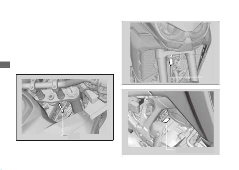
Vehicle Identification Number
352
Information
Vehicle Identification
Number
The VIN and engine serial number uniquely
identify your vehicle and are required in order to
register your vehicle. They may also be required
when ordering replacement parts.
You should record these numbers and keep
them in a safe place.
VIN
VIN
Engine number
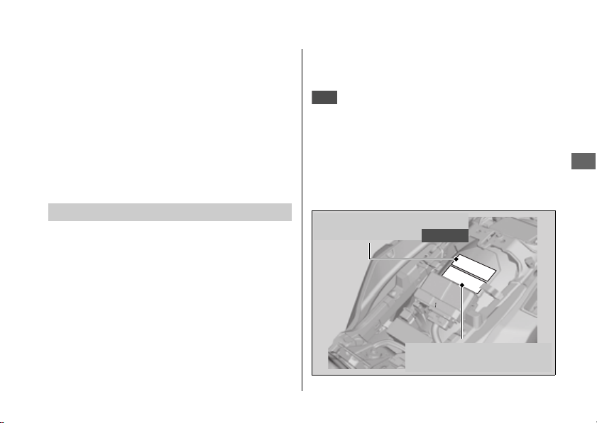
Emission Control Systems
353
Continued
Information
Emission Control Systems
Your vehicle engine emits combustion
byproducts, including carbon monoxide (CO),
oxides of nitrogen (NOx), and hydrocarbons
(HC). Gasoline evaporation also emits
hydrocarbons. Controlling the production of
NOx, CO, and HC is important for the
environment.
The U.S. Environmental Protection Agency (EPA),
the California Air Resources Board (CARB), and
Environment and Climate Change Canada
(ECCC) require that your vehicle comply with
applicable exhaust, crankcase, and fuel
permeation emission standards during its useful
life, when operated and maintained according to
the instructions provided.
CARB also requires that your vehicle comply with
applicable evaporative emission requirements
during its useful life, when operated and
maintained according to the instructions provided.
Compliance with the terms of the
Distributor's Warranties for Honda Motorcycle
Emission Control Systems is necessary in order to
maintain a valid emissions system warranty.
The Vehicle Emission Control Information label is
located the rear fender under the front seat.
2 P. 270
Exhaust Emission Requirements
USA
Vehicle emission control
information label
Vehicle emission control
information label
Canada

Emission Control Systems
354
Information
The EPA requires that vehicles built after January
1, 1983 comply with applicable noise emission
standards for one year or 3,730 miles (6,000 km)
after the time of purchase when operated and
maintained according to the instructions
provided.
The exhaust emission control system includes the
following components that should not need
adjustment, although periodic inspection by your
dealer is recommended.
#
PGM-FI System
The PGM-FI (programmed fuel injection) system
uses sequential multiport fuel injection, and is
comprised of air intake, engine control, fuel
control, and exhaust control subsystems. The
engine control module (ECM) uses sensors to
determine how much air enters the engine, and
then controls how much fuel to inject.
#
Ignition Timing Control System
The ignition timing control system adjusts the
ignition timing to reduce the amount of HC, CO,
and NOx produced.
#
Secondary Air Injection System
The secondary air injection system adds filtered
air into the exhaust gas to help improve emission
control performance.
#
Catalytic Converters
The exhaust system contains one or more
catalytic converters. Catalytic converters use a
catalyst to convert most of the harmful exhaust
gas compounds into harmless compounds.
An evaporative emissions control system uses a
canister filled with charcoal to adsorb fuel vapor
from the fuel tank while the engine is off. The
vapor is drawn into the engine and burned while
riding.
Noise Emission Requirements
Exhaust Emission Control System
Evaporative Emission Control System
50 STATE (meets California)

Emission Control Systems
355
Continued
Information
The engine is equipped with a closed crankcase
system to prevent discharging crankcase
emissions into the atmosphere.
Blow-by gas is returned to the combustion
chamber through the air cleaner and throttle
body.
The fuel tank, fuel hoses, and fuel vapor charge
hoses use fuel permeation control technologies
to prevent fuel vapor emissions. Tampering with
these components to reduce or defeat the
effectiveness of the fuel permeation
technologies is prohibited.
#
TAMPERING WITH THE NOISE CONTROL
SYSTEM IS PROHIBITED:
U. S. federal law prohibits, and Canadian
provincial laws may prohibit, the following acts or
the causing thereof: (1) The removal or
rendering inoperative by any person, other than
for purposes of maintenance, repair or
replacement, of any device or element of design
incorporated into any new vehicle for the
purpose of noise control prior to its sale or
delivery to the ultimate purchaser or while it is in
use; or (2) the use of the vehicle after such device
or element of design has been removed or
rendered inoperative by any person.
Crankcase Emissions Control System
Fuel Permeation Emission Control
Noise Emission Control System

Emission Control Systems
356
Information
#
AMONG THOSE ACTS PRESUMED TO
CONSTITUTE TAMPERING ARE THE
FOLLOWING ACTS:
● Removal of, or puncturing the muffler, baffles,
header pipes or any other component which
conducts exhaust gases.
● Removal of, or puncturing of any part of the
intake system.
● Lack of proper maintenance.
● Removing or disabling any emissions
compliance component, or replacing any
compliance component with a noncompliant
component.
Have your vehicle inspected and repaired by
your dealer if you experience any of the
following symptoms:
● Hard starting or stalling after starting
● Rough idling
● Misfiring or backfiring during acceleration
● Poor engine performance and poor fuel
economy
Problems Affecting Vehicle Exhaust
Emissions

Catalytic Converter
357
Information
Catalytic Converter
This vehicle is equipped with a three-way
catalytic converter. The catalytic converter
contains precious metals that serve as catalysts in
high temperature chemical reactions that
convert hydrocarbons (HC), carbon monoxide
(CO), and oxides of nitrogen (NOx) in the
exhaust gases into safe compounds.
A defective catalytic converter contributes to air
pollution and can impair your engine's
performance. A replacement unit must be an
original Honda part or equivalent.
Follow these guidelines to protect your vehicle's
catalytic converter.
● Always use unleaded gasoline. Leaded
gasoline will damage the catalytic converter.
● Keep the engine in good running condition. A
poorly running engine can cause the catalytic
converter to overheat, causing damage to the
converter or the vehicle.
● If your engine is misfiring, backfiring, stalling,
or otherwise not running properly, stop riding
and turn off the engine. Have your vehicle
serviced as soon as possible.

Oxygenated Fuels
358
Information
Oxygenated Fuels
Some conventional fuels blended with alcohol or
an ether compound are available in some locales
to help reduce emissions to meet clean air
standards. These gasolines are collectively
referred to as oxygenated fuels. If you plan to
use oxygenated fuel, check that it is unleaded
and meets the minimum octane rating and blend
requirement.
The following fuel blends have been approved
for use in your vehicle:
● Ethanol (ethyl alcohol) up to 10% by volume.
u Gasoline containing ethanol may be
marketed under the name Gasohol.
● Do not use gasoline containing methanol
(methyl alcohol).
If you accidentally fill your fuel tank with an
oxygenated fuel containing higher percentages,
you may experience performance problems. To
resolve the problem, have your dealer drain the
fuel tank and replace with the correct fuel. Fuel
system or performance problems resulting from
the use of an oxygenated fuel containing higher
percentages are not covered by your warranty.
If you notice any undesirable operating
symptoms or performance problems, try a
different brand of gasoline.
NOTICE
Improper use of oxygenated fuels can damage metal,
rubber, and plastic parts of your fuel system.
Oxygenated fuel can also damage paint. Damage caused
by spilled fuel is not covered by warranty.
Authorized Manuals
359
Information
Authorized Manuals
The Service Manual used by your
authorized dealer is available from your Honda
dealer or Helm, Inc.
See your dealer to order authorized
manuals.
Also available, but not necessary to service your
model, is the Honda Common Service Manual,
which explains basic service information for
various systems on Honda motorcycles, scooters,
ATV, and SxS.
The Winter Storage Guide in conjunction
with the Owner's Manual and Service Manual
can help you prepare your Honda motorcycle,
scooter, ATV, and SxS for winter storage.
These Honda manuals are written for the
professional technician. However, if you possess
the proper tools, observe the safety standards,
and are mechanically capable, you should find
them easy to use.
Special Honda tools are necessary for some
procedures.
Order online: www.helminc.com
Order Toll Free: 1-888-CYCLE93
(1-888-292-5393)
(NOTE: For Credit Card Orders Only)
Monday - Friday 8:00 AM - 6:00 PM EST
USA
Canada
USA
USA
Description
2022 CRF1100A/D/A4/D4 Service Manual
Common Service Manual (61CSM00)
Winter Storage Guide (S9507)
2022 CRF1100A/D/A4/D4 Owner’s Manual
USA

Warranty Coverage and Service
360
Information
Warranty Coverage and
Service
Your new Honda is covered by the following
warranties:
● Vehicle Limited Warranty
● Emission Control System Warranty
● Noise Control Warranty
The responsibilities, restrictions, and exclusions
that apply to these warranties are explained in
the Warranties Booklet given to you by your
Honda dealer at the time of purchase. Always
keep your Honda owner's card with your
Warranties Booklet.
Please refer to the Warranty Booklet
posted on our website at www.honda.ca.
It is important to realize that your warranty
applies only to defects in material or
workmanship of your Honda. Your warranty
coverage does not apply to the normal wear and
deterioration associated with use of the vehicle.
Your warranty coverage is not voided if you
perform your own maintenance. However,
failures that occur due directly to improper
maintenance are not covered by these
warranties.
You can extend almost all of your warranty
coverage through the HondaCare
®
Protection
Plan. For more information, see your Honda
dealer.
Coverage
USA
Canada
USA

Warranty Coverage and Service
361
Continued
Information
The Magnuson-Moss Warranty Act, 15 U.S.C.
s.2301 et seq., makes it illegal for motor vehicle
manufacturers to void a motor vehicle warranty
or deny warranty coverage solely because an
aftermarket or recycled part has been used to
repair the vehicle or someone other than the
authorized service provider performed service
on the vehicle. This provision does not apply to a
new motor vehicle purchased solely for
commercial or industrial use.
Under federal law, a manufacturer may deny
warranty coverage and charge for repairs to a
vehicle if it is discovered that an aftermarket or
recycled part installed on the vehicle is defective
or was installed incorrectly and caused damage
to another part of the vehicle otherwise covered
under warranty. The Federal Trade Commission
requires that a manufacturer demonstrate that
an aftermarket or recycled part or service
performed by a person other than an authorized
service provider caused damage to another part
of the vehicle otherwise covered under warranty
before denying warranty coverage. Additionally,
federal law allows a manufacturer to void a
motor vehicle warranty or deny warranty
coverage if the manufacturer provides the article
or service to consumers free of charge under the
warranty or the manufacturer has secured a
waiver from the Federal Trade Commission.
Please remember that maintenance
recommended in the Maintenance Schedule is
not included in your warranty coverage.
Statement on Warranty Coverage for
Aftermarket and Recycled Parts
Service

Warranty Coverage and Service
362
Information
If you believe you have a problem with your
vehicle, call the service department of your
Honda dealer. Make an appointment for an
inspection and diagnosis. You will be asked to
authorize that inspection, and your dealer will
return the results of the inspection. If a problem
exists and is covered under warranty, your dealer
will perform the warranty repairs. If you have any
questions about your warranty coverage or the
nature of the repair, talk to the Service Manager
of your Honda dealer.
If a misunderstanding occurs and you aren't
satisfied with your dealer's handling of the
situation, we suggest you discuss your problem
with the appropriate member of the dealership's
management team. If you are still not satisfied,
contact the owner of the dealership or their
designated representative.
Honda Contacts
363
Continued
Information
Honda Contacts
If you wish to contact Honda directly to
comment on your experiences with your vehicle
or with your dealer, please send your comments
using one of the following methods:
Powersports Customer Relations
American Honda Motor Co., Inc.
P.O. Box 2200, Torrance, CA 90509-2200
Mailstop: 100-4W-5F
Telephone: (866) 784-1870
Website: https://powersports.honda.com/
contact-us
Honda Canada Inc.
Customer Relations Department,
180 Honda Boulevard
Markham, Ontario
L6C 0H9
Telephone: (888) 946-6329
Fax: (877) 939-0909
E-mail: [email protected]
Please include the following information in your
letter:
● Name, address, and telephone number
● Product model, year, and VIN
● Date of purchase
● Dealer name and address
We will likely ask your Honda dealer to respond,
or possibly acknowledge your comments
directly.
American Honda Motor Co., Inc.
Canada

Honda Contacts
364
Information
The service department of your Honda dealer
offers trained personnel to perform regular
maintenance and unexpected repairs. It has the
latest available service information from Honda
and also handles warranty inspections and
repairs.
The parts department offers Honda Genuine
Parts, Pro Honda products, Honda Accessories
(USA only), and Honda accessories and products
(Canada only) that provide the same quality that
went into your vehicle.
The sales department offers the
HondaCare
®
Protection Plan to extend almost all
of your warranty coverage.
Your Honda dealer can also supply information
about riding events and information about safety
training available in your local area.
Your Honda Dealer
USA

Reporting Safety Defects
365
Continued
Information
Reporting Safety Defects
If you believe that your vehicle has a
defect which could cause a crash or
could cause injury or death, you should
immediately inform the National
Highway Traffic Safety Administration
(NHTSA) in addition to notifying
American Honda Motor Co., Inc.
If NHTSA receives similar complaints, it
may open an investigation, and if it
finds that a safety defect exists in a
group of vehicles, it may order a recall
and remedy campaign. However,
NHTSA cannot become involved in
individual problems between you, your
dealer, or American Honda Motor Co.,
Inc.
To contact NHTSA, you may call the
Vehicle Safety Hotline toll-free at:
1-888-327-4236
(TTY: 1-800-424-9153); go to
https://www.safercar.gov;
or write to:
Administrator, NHTSA,
1200 New Jersey Avenue, SE.,
Washington, DC 20590.
You can also obtain other information
about motor vehicle safety from:
https://www.safercar.gov.
USA

Reporting Safety Defects
366
Information
If you believe that your vehicle has a
defect which could cause a crash or
could cause injury or death, you should
immediately inform Honda Canada Inc.
and you may also inform Transport
Canada.
If Transport Canada receives similar
complaints, it may open an
investigation, and if it finds that a safety
defect exists in a group of vehicles, it
may lead to a recall and remedy
campaign. However, Transport Canada
cannot become involved in individual
problems between you, your dealer, or
Honda Canada Inc.
To contact Transport Canada’s Defect
Investigations and Recalls Division,
Mailing Address:
Transport Canada - ASFAD
330 Sparks Street
Ottawa, ON
K1A 0N5
Telephone: 819-994-3328 (Ottawa-
Gatineau area or internationally)
Toll free: 1-800-333-0510 (in Canada)
Online:
(English Link:) www.tc.canada.ca/
recalls
(French Link:) www.tc.canada.ca/
rappels
Canada

Reporting Safety Defects
367
Information
For more information on reporting
safety defects or about motor vehicle
safety, go to
https://www.tc.gc.ca/roadsafety.

Legal Information on Apple CarPlay/Android Auto
368
Information
Legal Information on
Apple CarPlay/Android
Auto
USE OF APPLE CARPLAY IS SUBJECT TO YOUR
AGREEMENT TO THE CARPLAY TERMS OF USE,
WHICH ARE INCLUDED AS PART OF THE APPLE
iOS TERMS OF USE. IN SUMMARY, THE
CARPLAY TERMS OF USE DISCLAIM APPLE AND
ITS SERVICE PROVIDERS’ LIABILITY IF THE
SERVICES FAIL TO PERFORM CORRECTLY OR
ARE DISCONTINUED, STRICTLY LIMIT APPLE
AND ITS SERVICE PROVIDERS’ OTHER
LIABILITIES, DESCRIBE THE KINDS OF USER
INFORMATION (INCLUDING, FOR EXAMPLE,
VEHICLE LOCATION, VEHICLE SPEED, AND
VEHICLE STATUS) BEING GATHERED AND
STORED BY APPLE AND ITS SERVICE
PROVIDERS, AND DISCLOSE CERTAIN POSSIBLE
RISKS ASSOCIATED WITH THE USE OF
CARPLAY, INCLUDING THE POTENTIAL FOR
DRIVER DISTRACTION.
SEE APPLE’S PRIVACY POLICY FOR DETAILS
REGARDING APPLE'S USE AND HANDLING OF
DATA UPLOADED BY CARPLAY.
OWNER’S MANUAL LICENSE/LIABILITY
STATEMENTS

Legal Information on Apple CarPlay/Android Auto
369
Continued
Information
USE OF ANDROID AUTO IS SUBJECT TO YOUR
AGREEMENT TO THE ANDROID AUTO TERMS
OF USE WHICH MUST BE AGREED TO WHEN
THE ANDROID AUTO APPLICATION IS
DOWNLOADED TO YOUR ANDROID PHONE. IN
SUMMARY, THE ANDROID AUTO TERMS OF
USE DISCLAIM GOOGLE AND ITS SERVICE
PROVIDERS’ LIABILITY IF THE SERVICES FAIL TO
PERFORM CORRECTLY OR ARE
DISCONTINUED, STRICTLY LIMIT GOOGLE AND
ITS SERVICE PROVIDERS’ OTHER LIABILITIES,
DESCRIBE THE KINDS OF USER INFORMATION
(INCLUDING, FOR EXAMPLE, VEHICLE
LOCATION, VEHICLE SPEED, AND VEHICLE
STATUS) BEING GATHERED AND STORED BY
GOOGLE AND ITS SERVICE PROVIDERS, AND
DISCLOSE CERTAIN POSSIBLE RISKS
ASSOCIATED WITH THE USE OF ANDROID
AUTO, INCLUDING THE POTENTIAL FOR
DRIVER DISTRACTION.
SEE GOOGLE’S PRIVACY POLICY FOR DETAILS
REGARDING GOOGLE’S USE AND HANDLING
OF DATA UPLOADED BY ANDROID AUTO.

Legal Information on Apple CarPlay/Android Auto
370
Information
YOU EXPRESSLY ACKNOWLEDGE AND AGREE
THAT USE OF APPLE CARPLAY OR ANDROID
AUTO (“THE APPLICATIONS”) IS AT YOUR SOLE
RISK AND THAT THE ENTIRE RISK AS TO
SATISFACTORY QUALITY, PERFORMANCE,
ACCURACY AND EFFORT IS WITH YOU TO THE
MAXIMUM EXTENT PERMITTED BY APPLICABLE
LAW, AND THAT THE APPLICATIONS AND
INFORMATION ON THE APPLICATIONS IS
PROVIDED “AS IS” AND “AS AVAILABLE,” WITH
ALL FAULTS AND WITHOUT WARRANTY OF
ANY KIND, AND HONDA HEREBY DISCLAIMS
ALL WARRANTIES AND CONDITIONS WITH
RESPECT TO THE APPLICATIONS AND
INFORMATION ON THE APPLICATIONS, EITHER
EXPRESS, IMPLIED OR STATUTORY, INCLUDING,
BUT NOT LIMITED TO, THE IMPLIED
WARRANTIES AND/OR CONDITIONS OF
MERCHANTABILITY, SATISFACTORY QUALITY,
FITNESS FOR A PARTICULAR PURPOSE,
ACCURACY, QUIET ENJOYMENT, AND
NONINFRINGEMENT OF THIRD PARTY RIGHTS.
NO ORAL OR WRITTEN INFORMATION OR
ADVICE GIVEN BY HONDA OR AN
AUTHORIZED REPRESENTATIVE SHALL CREATE
A WARRANTY. AS EXAMPLES, AND WITHOUT
LIMITATION, HONDA DISCLAIMS ANY
WARRANTY REGARDING THE ACCURACY OF
DATA PROVIDED BY THE APPLICATIONS, SUCH
AS THE ACCURACY OF DIRECTIONS,
ESTIMATED TRAVEL TIME, SPEED LIMITS, ROAD
CONDITIONS, NEWS, WEATHER, TRAFFIC, OR
OTHER CONTENT PROVIDED BY APPLE,
GOOGLE, THEIR AFFILIATES, OR THIRD PARTY
PROVIDERS; HONDA DOES NOT GUARANTEE
AGAINST LOSS OF APPLICATION DATA, WHICH
MAY BE LOST AT ANY TIME; HONDA DOES
NOT GUARANTEE THAT THE APPLICATIONS OR
ANY SERVICES PROVIDED THROUGH THEM
WILL BE PROVIDED AT ALL TIMES OR THAT ANY
OR ALL SERVICES WILL BE AVAILABLE AT ANY
PARTICULAR TIME OR LOCATION.
DISCLAIMER OF WARRANTIES;
LIMITATION ON LIABILITY

Legal Information on Apple CarPlay/Android Auto
371
Information
FOR EXAMPLE, SERVICES MAY BE SUSPENDED
OR INTERRUPTED WITHOUT NOTICE FOR
REPAIR, MAINTENANCE, SECURITY FIXES,
UPDATES, ETC., SERVICES MAY BE
UNAVAILABLE IN YOUR AREA OR LOCATION,
ETC. IN ADDITION, YOU UNDERSTAND THAT
CHANGES IN THIRD PARTY TECHNOLOGY OR
GOVERNMENT REGULATION MAY RENDER THE
SERVICES AND/OR APPLICATIONS OBSOLETE
AND/OR UNUSABLE.
TO THE EXTENT NOT PROHIBITED BY LAW, IN
NO EVENT SHALL HONDA OR ITS AFFILIATES
BE LIABLE FOR PERSONAL INJURY, OR ANY
INCIDENTAL, SPECIAL, INDIRECT OR
CONSEQUENTIAL DAMAGES WHATSOEVER,
INCLUDING, WITHOUT LIMITATION, DAMAGES
FOR LOSS OF PROFITS, CORRUPTION OR LOSS
OF DATA, FAILURE TO TRANSMIT OR RECEIVE
ANY DATA, BUSINESS INTERRUPTION OR ANY
OTHER COMMERCIAL DAMAGES OR LOSSES,
ARISING OUT OF OR RELATED TO THE
APPLICATIONS OR YOUR USE OF OR INABILITY
TO USE THE APPLICATIONS OR INFORMATION
ON THE APPLICATIONS, HOWEVER CAUSED,
REGARDLESS OF THE THEORY OF LIABILITY
(CONTRACT, TORT OR OTHERWISE) AND EVEN
IF HONDA WERE ADVISED OF THE POSSIBILITY
OF SUCH DAMAGES. SOME REGIONS AND
JURISDICTIONS MAY DISALLOW THE
EXCLUSION OR LIMITATION OF LIABILITY FOR
DAMAGES, SO THESE LIMITATIONS AND
EXCLUSIONS MAY NOT APPLY TO YOU. THE
FOREGOING LIMITATIONS WILL APPLY EVEN IF
THE ABOVE STATED REMEDY FAILS OF ITS
ESSENTIAL PURPOSE.

Software Upgrades
372
Information
Software Upgrades
Honda is continually expanding the scope of the
system software. The softwares are updated to
correspond with new version releases.
For the software updates, contact your dealer.
Upgrades
373
Specifications
Specifications
Specifications
Specif ications
■ Main Components
*1:
Including rider, passenger, all luggage, and accessories
Overall length 91.7 in (2,330 mm)
Overall width 37.8 in (960 mm)
Overall height
54.9 in (1,395 mm)
Highest position
60.8 in (1,545 mm)
Lowest position
58.7 in (1,490 mm)
Wheelbase 62.0 in (1,575 mm)
Minimum ground clearance 9.8 in (250 mm)
Caster angle 27.5°
Trail 4.4 in (113 mm)
Curb weight
505 lb (229 kg)
527 lb (239 kg)
529 lb (240 kg)
551 lb (250 kg)
CRF1100A/D
CRF1100A4/D4
CRF1100A
CRF1100D
CRF1100A4
CRF1100D4
Maximum weight capacity
*1
450 lb (204 kg)
Maximum weight on rear
carrier
22 lb (10 kg)
Passenger capacity Rider and 1 passenger
Minimum turning radius 8.5 ft (2.6 m)
Displacement 66.1 cu-in (1,084 cm
3
)
Bore x stroke 3.62 x 3.21 in (92.0 x 81.5 mm)
Compression ratio 10.1:1
Fuel
Unleaded gasoline
Recommended: 86 PON or higher
Tank capacity
4.97 US gal (18.8 L)
6.55 US gal (24.8 L)
CRF1100A/D
CRF1100A4/D4
Specifications
374
Specifications
■ Service Data
Battery
HY110
12 V-6 Ah (20 HR)
Gear ratio
1st 2.866
2nd 1.888
3rd 1.480
4th 1.230
5th 1.064
6th 0.972
1st 2.562
2nd 1.761
3rd 1.375
4th 1.133
5th 0.972
6th 0.882
Reduction ratio
(primary / final)
1.717 / 2.625
1.863 / 2.625
CRF1100A/A4
CRF1100D/D4
CRF1100Aa/A4
CRF1100D/D4
Tire size
Front 90/90-21M/C 54H
Rear 150/70R18M/C 70H
Tire type
Front
Bias-ply, tube
Bias-ply, tubeless
Rear
Radial, tube
Radial, tubeless
CRF1100A/D
CRF1100A4/D4
CRF1100A/D
CRF1100A4/D4
Specifications
375
Specifications
Recommended
Tire
Front
BRIDGESTONE BATTLAX
ADVENTURECROSS TOURER
AX41TF G
METZELER KAROO STREET
BRIDGESTONE BATTLAX
ADVENTURECROSS TOURER
AX41TF L
METZELER KAROO STREET
Rear
BRIDGESTONE BATTLAX
ADVENTURECROSS TOURER
AX41TR G
METZELER KAROO STREET
BRIDGESTONE BATTLAX
ADVENTURECROSS TOURER
AX41TR L
METZELER KAROO STREET
Tire air pressure
(Up to 90 kg (200
lbs) load)
Front 33 psi (225 kPa, 2.25 kgf/cm
2
)
Rear 36 psi (250 kPa, 2.50 kgf/cm
2
)
Tire air pressure
(Up to maximum
weight capacity)
Front 33 psi (225 kPa, 2.25 kgf/cm
2
)
Rear 41 psi (280 kPa, 2.80 kgf/cm
2
)
Minimum tread
depth
Front 0.06 in (1.5 mm)
Rear 0.08 in (2.0 mm)
CRF1100A/D
CRF1100A4/D4
CRF1100A/D
CRF1100A4/D4
Spark plug (standard) SILMAR8A9S (NGK)
Spark plug gap
(non-
adjustable)
0.03 - 0.04 in (0.8 - 0.9 mm)
Idle speed
(non-
adjustable)
1,250 ± 100 rpm
Recommended
engine oil
API Service Classification SJ or higher except oils
labeled as energy conserving or resource
conserving on the circular API service label, SAE
10W-30, JASO T 903 standard MA, Pro Honda
GN4 4-stroke oil (USA & Canada) or Honda 4-
stroke oil, or an equivalent motorcycle oil
Engine oil
capacity
After draining 4.1 US qt (3.9 L)
After draining &
engine oil filter
change
4.2 US qt (4.0 L)
After disassembly 5.1 US qt (4.8 L)
After draining 4.2 US qt (4.0 L)
After draining &
engine oil filter
change
4.4 US qt (4.2 L)
After draining,
engine & clutch oil
filter change
4.4 US qt (4.2 L)
After disassembly 5.5 US qt (5.2 L)
CRF1100A/A4
CRF1100D/D4
Specifications
376
Specifications
■ Bulbs
■ Fuses
■ Torque Specifications
Recommended
brake fluid
Honda DOT 4 Brake Fluid
Cooling system
capacity
1.91 US qt (1.81 L)
Recommended
coolant
Pro Honda HP Coolant
Recommended
drive chain
lubricant
Pro Honda HP Chain Lube or equivalent
Drive chain slack 1 7/8 - 2 1/16 in (48 - 53 mm)
Standard drive
chain
DID 525HV3
No. of links 124
Standard
sprocket size
Drive sprocket 16T
Driven sprocket 42T
Headlight LED
Cornering light
LED
Brake light/Taillight LED
Front turn signal LED
Rear turn signal LED
License plate light LED
CRF1100A4/D4
Main fuse 30 A
Other fuse 30 A, 20 A, 15 A, 10 A, 3A
Spark arrester mounting bolt 6.6 lbf·ft (9.0 N·m, 0.9 kgf·m)
Tail cap mounting bolt 6.6 lbf·ft (9.0 N·m, 0.9 kgf·m)
377
Information Record
VIN
Engine No.
Color Label & Code
Owner's Name
Address
City/State
Phone
Dealer's Name
Address
City/State
Phone
Service Manager

California Proposition 65 Warning
WARNING: Operating, servicing and maintaining a passenger vehicle
or off-highway motor vehicle can expose you to chemicals including
engine exhaust, carbon monoxide, phthalates, and lead, which are known
to the State of California to cause cancer and birth defects or other
reproductive harm. To minimize exposure, avoid breathing exhaust, do
not idle the engine except as necessary, service your vehicle in a well-
ventilated area and wear gloves or wash your hands frequently when
servicing your vehicle. For more information go to
www.P65Warnings.ca.gov/passenger-vehicle.

PRINTED IN USA
31MLG800
00X31-MLG-8000