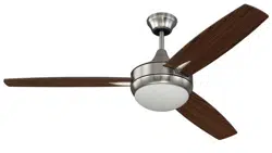
Installation Guide for Craftmade TG52GBK3
Table of contents
- Safety Tips.
- Unpacking Your Fan
- Parts Inventory.
- Installation Preparation
- Hanging Bracket Installation
- Fan Assembly.
- Wiring.
- Wiring-Wall Control
- Canopy Assembly
- Shade Installation
- Wall Control Operation
- Testing Your Fan
- Troubleshooting
- Parts Replacement
- Warranty
Installation Preparation.
To prevent personal injury and damage, ensure that the hanging location allows the blades a clearance of 7 feet (2.13m) from the floor and 30in. (76cm) from any wall or obstruction. The 48in fan is suitable for room sizes up to 225 square feet (20.9 square meters). The 52in fan is suitable for room sizes up to 400 square feet (37.2 square meters).
This fan can be mounted with a downrod on a regular (no-slope) or vaulted ceiling. The hanging length can be extended by purchasing a longer downrod (0.5in./1.27cm diameter). Other installation, such as flushmount, is not available for this fan.
Installation requires these tools: Phillips screwdriver, flathead screwdriver, adjustable pliers or wrench, stepladder, wire cutters, and rated electrical tape.
Hanging Bracket Installation.
Turn off circuit breakers to current fixture from breaker panel and be sure operating light switch is turned to the OFF position.
WARNING: Failure to disconnect power supply prior to installation may result in serious injury.
Remove existing fixture.
WARNING: When using an existing outlet box, be sure the outlet box is securely attached to the building structure and can support the full weight of the fan. Ensure outlet box is clearly marked "Suitable for Fan Support." If not, it must be replaced with an approved outlet box. Failure to do so can result in serious injury.
CAUTION: Be sure outlet box is properly grounded and that a ground wire (GREEN or bare) is present.
Install hanging bracket to outlet box using original screws, spring washers and flat washers provided with new or original outlet box.* If installing on a vaulted ceiling, face opening of hanging bracket towards high point of ceiling.
Arrange electrical wiring around the back of the hanging bracket and away from the bracket opening.
Note: It is very important that you use the proper hardware when installing the hanging bracket as this will support the fan.
Fan Assembly
Remove 6 screws and washers from yoke plate located on top plate on top of motor housing) and set aside. Lift yoke plate and top plate to remove from motor housing and set aside.
Time Saver: Washers can be set on each blade plate screw prior to installing blades.
WARNING: To reduce the risk of serious bodily injury, DO NOT use power tools to assemble the blades. If overtightened, blades may crack and break.
Locate 9 decorative blade plate attachment screws and washers in one of the hardware packs. Hold blade plate up to blade, aligning posts in blade plate with holes in blade as shown in diagram. Insert 3 blade plate attachment screws (along with washers) with fingers first and then tighten screws securely with a Phillips screwdriver. Repeat for the remaining blade plates.
Locate 9 blade attachment screws/washers in hardware pack. Slide blade through one of the narrow, rectangular openings on center band, aligning holes in blade with holes in blade arm located inside motor housing). Insert 3 blade attachment screws/washers with fingers first and then tighten screws securely with a Phillips screwdriver. Repeat procedure for each remaining blade.
Re-attach top plate and yoke plate to yoke using washers and screws previously removed.
Be sure that semicircular cutout on top plate and yoke plate aligns over yoke set screws for a proper fit. (Also make sure that reverse switch aligns properly with hole for reverse switch in top plate--see drawing.) Tighten screws to secure top plate and yoke plate.
[Fan Assembly" continued on next page.]
Remove hanging ball from downrod provided by loosening set screw on hanging ball. Remove pin and clip. Lower hanging ball and remove stop pin.
Slide hanging ball off of the downrod. [Refer to diagram 1.]
Loosen yoke set screws and nuts at top of motor housing. [Refer to diagram 2.]
Tip: To prepare for threading electrical wires through downrod, apply a small piece of electrical tape to the ends of the electrical wires--this will keep the wires together when threading them through the downrod. [Refer to diagram 2.]
Determine the length of downrod you wish to use. Thread safety cable and electrical wires through threaded end of downrod and pull extra wire slack from the upper end of the downrod.
[ Refer to diagram 2.]
Thread downrod into the motor housing yoke until holes for pin and clip in downrod align with holes in yoke--make sure wires do not get twisted.
Re-insert pin and clip that were previously removed. Tighten yoke set screws and nuts securely. [Refer to diagram 2.]
Locate canopy cover in hardware pack. Slide yoke cover, canopy cover and canopy over downrod.
[ Refer to diagram 3.] (Note: Canopy cover must be turned with shiny side toward the motor housing.)
Thread safety cable and wires through hanging ball; then slide hanging ball over downrod--the top of the downrod should be noted as having a set screw hole; use this hole when setting the set screw. Insert stop pin into top of downrod and raise hanging ball. Be sure stop pin aligns with slots on the inside of the hanging ball. Tighten set screw securely. [Refer to diagram 4.]
WARNING: Failure to tighten set screw on hanging ball completely could result in the fan becoming loose and possibly falling.
[ Fan Assembly" continued on next page.] diagram 1
NOTE: The important safety precautions and instructions appearing in the manual are not meant to cover all possible conditions and situations that may occur. It must be understood that common sense and caution are necessary factors in the installation and operation of this fan.
With the hanging bracket secured to the outlet box and able to support the fan, you are now ready to hang your fan. Grab the fan firmly with two hands. Slide downrod through opening in hanging bracket and let hanging ball rest on the hanging bracket. Turn the hanging ball slot until it lines up with the hanging bracket tab.
WARNING: Failure to align slot in hanging ball with tab in hanging bracket may result in serious injury or death.
Tip: Seek the help of another person to hold the stepladder in place and to lift the fan up to you once you are set on the ladder.
Find a secure attachment point (wood ceiling joist highly recommended) and secure safety cable. It will be necessary to use a heavy duty wood screw, washer and lock washer (not supplied) with the safety cable loop. If necessary, adjust the loop at the end of the safety cable. The loop at the end of the safety cable should just fit over the threads on the wood screw. Test safety cable by pulling on loose end with pliers. If the safety cable slips, the loop must be adjusted tighter. Extra cable slack can be left in ceiling area.
Wiring.
WARNING: Turn off circuit breakers to current fixture from breaker panel and be sure operating light switch is turned to the OFF position.
CAUTION: Be sure outlet box is properly grounded and that a ground wire (GREEN or Bare) is present.
Make sure all electrical connections comply with Local Codes or Ordinances and the National Electrical Code. If you are unfamiliar with electrical wiring or if the house/building wires are different colors than those referred to below, please use a qualified electrician.
Note: Excess lead wire length from the fan can be cut to the desired length and then stripped.
When downrod is secured in place on the hanging bracket, electrical wiring can be made as follows: Connect BLACK and BLUE wire from fan to BLACK wire from ceiling with wire connector provided. Connect WHITE wire from fan to WHITE wire from ceiling with wire connector provided. Connect all GROUND (GREEN) wires together from fan to BARE/GREEN wire from ceiling with wire connector provided.
If you intend to control the fan light with a separate light switch, connect BLUE wire from fan to the BLACK (or RED) supply from the independent switch.
Wiring - Wall Control
Remove existing wall switch. Wire the wall control as shown in diagram at right.
Connect BLACK/WHITE wire from wall control to BLACK (AC IN L) wire in outlet box. Connect BLACK wire from wall control to BLACK (AC IN N) wire from fan (inside the outlet box). Connect BLUE wire from wall control to BLUE wire from light in the outlet box. Connect GREEN/YELLOW ground wire from wall control to ground wire in the outlet box. Use wire connectors provided when making connections.
*Wrap each wire connector separately with electrical tape as an extra safety measure. Gently push wires and taped wire connectors into outlet box.
Attach wall control to outlet box and secure with screws from original wall switch. Attach plate (included) to wall control using 2 screws provided with the wall control.
Canopy Assembly
Locate 2 screws on underside of hanging bracket and remove screw closest to the open end of the hanging bracket. Partially loosen the other screw. Lift canopy to hanging bracket. Place rounded part of slotted hole in canopy over loosened screw in hanging bracket and push up. Twist canopy to lock. Re-insert screw that was removed and then tighten both screws securely.
Slide canopy cover up to canopy, aligning rounded part of slotted holes in canopy cover with screwheads in bottom of canopy. Turn canopy cover to the right (clockwise) until it stops
Shade Installation.
Locate slots on shade and align with nodules on underside of motor housing. Gently push up on shade and turn to the RIGHT (clockwise) until it slides completely into place.
Pull down gently on shade to make sure shade is secured completely
Wall Control Operation.
The wall control is operational for fan and light (dimmer).
Testing Your Fan.
It is recommended that you test fan before finalizing installation. Slide the knobs to “O” (OFF) position in wall control. Restore power from circuit box. Test light and dimmer function and then test fan speeds. If fan and/or light do (does) not function, please refer to "Troubleshooting" section to solve any issues before contacting Customer Service.
Turn fan completely off before moving the reverse switch. Set reverse switch to recirculate air depending on the season:
- LEFT position in summer (diagram 1)
- RIGHT position in winter (diagram 2)
A ceiling fan will allow you to raise your thermostat setting in summer and lower your thermostat setting in winter without feeling a difference in your comfort.
Important: Reverse switch must be set either completely LEFT or completely RIGHT for fan to function. If the reverse switch is set in the middle position (diagram 3), fan will not operate.