MANUAL
iCaution:
Read and Follow
_ All Safety Rules
and Instructions
i Before Operating
This Equipment
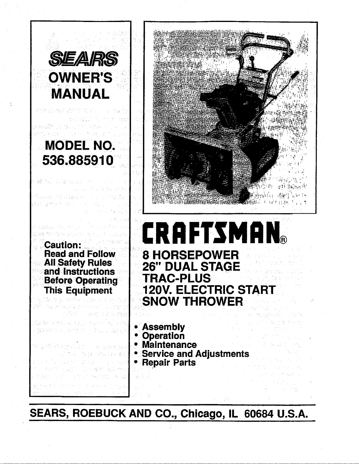
CRAFTSMAN®
8 HORSEPOWER
26" DUAL STAGE
TRAC-PLUS
120V. ELECTRIC START
SNOW THROWER
• Assembly
Operatzon
Maintenance
• Service and Adjustments
- RePair Parts
SEARS,. ROEBUCK AND CO., Chicago, IL 60684 ,U.S.A.
f . i r • n i| mini li : i i • i

SAFETY RULES
CAUTION: ALWAYS DISCONNECT SPARK PLUG WIRE AND PLACE A
WiRE WHERE IT CANNOT CONTACT SPARK PLUG TO PREVENT
ACCIDENTAL STARTING WHEN SE'I-I'ING-UP, TRANSPORTING,
ADJUSTING OR MAKING REPAIRS:
IMPORTANT
SAFETY STANDARDS REQUIRE OPERATOR PRESENCE CONTROLS TO MINIMIZE THE
RISK OF INJURY. YOUR SNOW THROWER IS EQUIPPED WITH SUCH CONTROLS. DO NOT
ATTEMPT TO DEFEAT THE FUNCTION OF THE OPERATOR PRESENCE CONTROL UNDER
ANY CIRCU MSTANCES.
BEFORE USE
• Read the Owner's Manual carefully. Be thor-
oughlyfamiliar with the controls arid the proper
use ofthe snow thrower. Know how to stop the
show thrower and disengage the controls
quickly.
:o Do notoperatethesnowthrowerwithoutwear-
ing adequate winter outer garments. Wear
footwear that will improve footing on slippery
surfaces.
o Keepthe area ofoperation clearof all persons,
particularly small children, and pets.
• Thoroughly inspect the area where the snow
thrower isto be used and remove all doormats,
sleds, boards, wires, and other foreign objects.
• Use extension cords and receptacles as speci-
fied by the manufacturer for all .snow throwers
with electric drive motors or electdc starting
motors.
• Use only attachments and accessories ap-
provedbythe manufacturerofthesnowthrower
(such as tire chains, electdc start kits, etc.)
• Never operate the snow thrower without good
visibilityor light. Always be sure ofyourfooting,
and keep a firm hold on the handles. Walk;
never run.
• This snow thrower is for use on sidewalks,
driveways, and other ground level surfaces.
CAUTION should be exercised while using on
steep sloping surfaces. DO NOT USE SNOW
THROWER ON SURFACES ABOVE
GROUND LEVEL such as roofs ofresidences,
garages, porches or other such structures or
buildings,
• Check shear bolts and other bolts at frequent
intervals for proper tightness to be sure the
snow thrower is in safe working condition.
• Disengage all clutches and shift into neutral
before starting the engine.
• Adjust the snow thrower height to clear gravel
.... or crushed rock surface.
• _Let engine andsnow thrower adjust to outdoor
..... temperatures before starting to clear snow.
," '0
D
FUEL SAFETY
• Handle fuel with care; it is highly flammable.
• Use an approved fuel container.
• Check fuel supply before each use, allowing
space for expansion as the heat of the engine
and/or sun can cause fuei_to expand.
Fill fueltankoutdoorswith extreme care. Never
fill fuel tank indoors.
Replace fuel tank cap Securely and wipe up
spilled fuel.
• Never remove fuel tank cap or add fuel to a
running engine or hot engine.
= Never store fuel orsnowthrcwer with fuel inthe
tank inside of a building where fumes may
reach an open flame or spark.
OPERATING SAFETY
• _ Never allow children or young teenagers to
operate the snow throwerand keep them away
while it :is operating. Never allow adults to
operate ,the snow thrower without proper in-_
struction. Do not carry passengem.:
Always wear safety glasses or eye shields
• during operation orwhile performing an adjust,
ment or repair to protect eyes from foreign
objects that may be thrown from the snow
thrower.
• Exercise extreme caution when operating on
or crossing gravel ddves, walks, or roads. Stay
alert for hidden hazards or traffic.
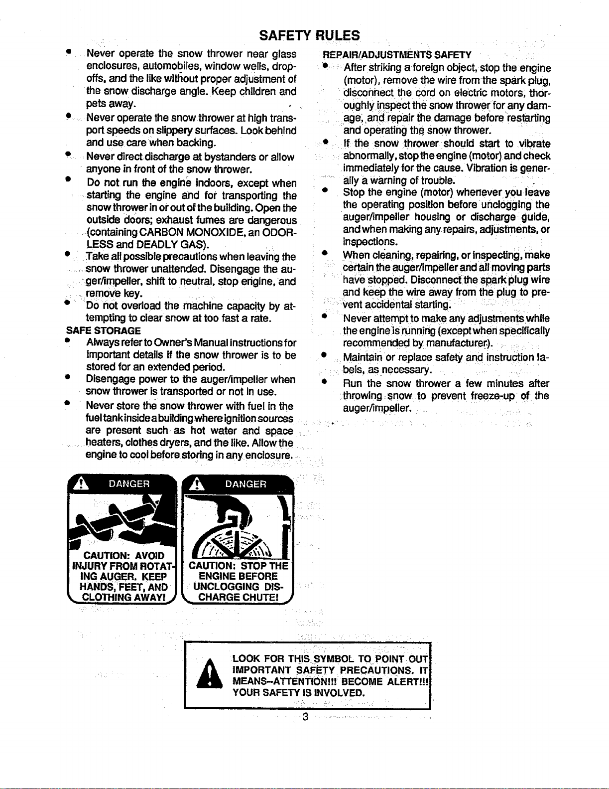
• Do not put hands or feet near or under rotating
parts. Keep clear of the discharge opening at
all times.
Exercise caution to avoid slipping or falling, es-
pecially when operating in reverse.
Do not clear snow across the face of slopes.
Exercise caution when changing direction on
slopes. Do not attempt to clear steep slopes.
• Never operate thesnow thrower without proper
guards, plates or other safety protective de-
vices in place ......
°
I
2
/i
• r:'
SAFETY RULES
• Never operate the snow thrower near glass
enclosures, automobiles, window wells, drop-
offs, and the like without proper adjustment of
' the snow discharge angle. Keep children and
pets away.
• .... Never operate the snow thrower at high trans-
port speeds on slippery surfaces. Look behind
and use care when backing.
• . Never directdischarge at bystanders or allow
- anyone in front of the snow thrower.
• Do not run the engine indoors, except when
starting the engine and for transporting the
snow thrower inor out of the building. Open the
= ,
outside doors; exhaust fumes are dangerous
.(containing CARBON MONOXIDE, an ODOR-
LESS and DEADLY GAS).
• Take all possible precautions when leaving the
........snow thrower unattended. Disengage the au-
:" ger/impeller, shift to neutral, stop erigine, and
• .: remove key .... ....
•-_ Do not overload the machine capacity by at-
tempting to clear snow at too fast a rate.
SAFE STORAGE
• Always refer toOwner's Manual instructions for
important details if the snow thrower is to be
stored for an extended period.
• Disengage power to the auger/impeller when
snow thrower is transported or not in use.
• Never store the snow thrower with fuel in the
REPAIRIADJUSTMENTS SAFETY
• After striking aforeign object, stop the engine
(motor), remove the wire from the spark plug,
disconnect the Cord on electric motors, thor-
=
oughly !nsPect the snow thrower for any dam-
age, _and.repair the damage before restarting
and Operating th_ snow thrower.
..e If the snow thrower should start to vibrate
abnormally, stop the engine (motor) and check
immediately for the cause. Vibration is gener-
" ally a warning of trouble.
• Stop the engine (motor) whenever you leave
the operating position before unclogging the
auger/impeller housing or discharge guide,
and when making any repairs, adjustments, or
inspections.
• When cle'aning, repairing, or inspecting, make
certain the auger/impeller and all moving parts
have stopped. Disconnectthe spark plug wire
and keep the wire away from the plug to pre-
-;ventaccidental Starting. " : -
• Never attempt to make any adjustmentswhile
the engine is running (except when specifically
recommended by.manufacturer,).
• Maintain or replace safety and instruction la-
bels, as necessary.
• Run the snow thrower a few minutes after
throwing snow to prevent freeze-up of the
auger/impeller- . •
fuel t_.nkinsideabuilding whereignition sources ........... '
are present such. as hot water and space ....:
• heaters, clothes dryers, and the like. Allow the .....
engine to cool before storing in any enc!osure .......
UNCLOGGING DIS-
i¸&
LOOK FOR THIS SYMBOL TOPOINT OUT
IMPORTANT SAFETY PRECAUTIONS. IT
MEANS--ATTE NTION!!! BECOME •ALERT!!!
YOUR SAFETY IS INVOLVED.
.... , , •
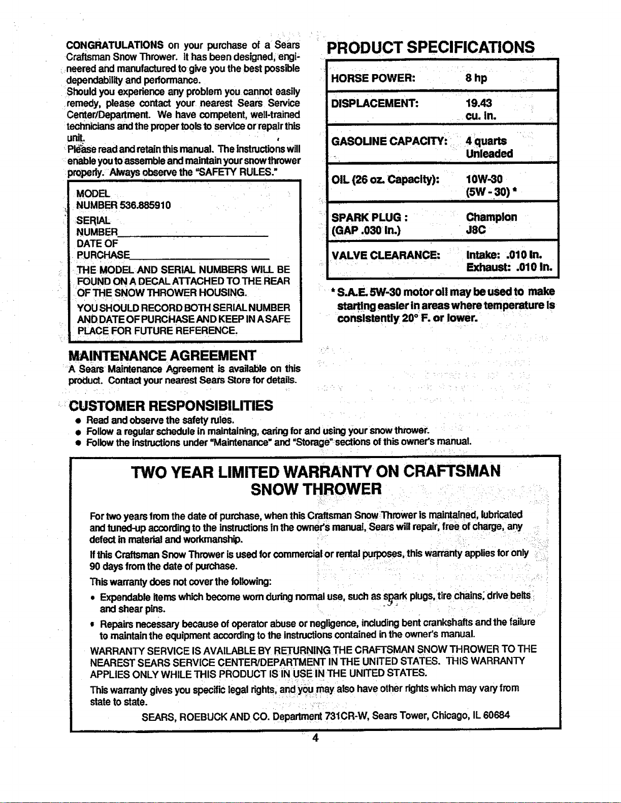
CONGRATULATIONS on your purchase of a Sears
CraftsmanSnow Thrower. tt has been designed;engi-
neered and manufacturedto give youthe best possible
dependabilityand performance.
Shouldyou experience any problem you cannot easily
remedy, please contact your nearest Sears Service
CenterlDepartrnent. We have competent, we,-trained
techniciansandthe propertoolstoservice orrepair this
unit.
PId_zseread andretainthis manual. The instructionswill
enableyoutorassembleand maintain yoursnowthrower
pr0pedy. .AIways observethe "SAFETY RULES."
MODEL
NUMBER 536.885910
SERIAL
NUMBER
DATE OF
PURCHASE.
THE MODELAND SERIAL NUMBERS WILL BE
FOUND ON A DECAL ATTACHED TOTHE REAR
OF THE SNOW THROWER HOUSING.
YOU SHOULD RECORD BOTH SERIAL NUMBER
AND DATE OF PURCHASE AND KEEP INASAFE
PLACE FOR FUTURE REFERENCE.
MAINTENANCE AGREEMENT
A Sears Maintenance Agreement is available on this
product. Contactyournearest Sears Store for details.
PRODUCT SPECIFICATIONS
HORSE POWER: 8 hp
DISPLACEMENT: 19.43
cu. in.
i JJ ,,
GASOUNE CAPACITY: = 4 quarts
_ Unleaded
III Ill i i iii
OIL (26 oz. Capacity): 10W-3O
(sw -3o)*
i ii iiii
SPARK PLUG : Champion
(GAP .030 in.) J8C
H i
VALVE CLEARANCE: Intake: .010 In.
Exhaust: .010 In.
* S,A.E 5W-3O motor oi! may be used to make
start!ng easier in areas where temperature is
consistently 20° F. or lower.
-'=CUSTOMER RESPONSIBILITIES
• Read and observethe safety rules.
• Followa regularschedulein maintaining,cadngfor and usingyoursnow thrower.
• Followthe instructionsunder=Maintenance" and "Storage'sections ofthisowner's manual.
i i ]i illilili 1 ii
TWO YEAR LIMITED WARRANTY ON CRAFTSMAN
SNOW THROWER
Fortwoyears fromthe date of purchase,when thisCraftsmanSnowThrower is maintained,lubricated
andtuned-up according to the instructionsinthe owner's manual, Searswill repair,free of charge, any
defectin materialand workmanship.
Ifthis CraftsmanSnow Thrower is used forcommercial or rentalpurposes, this warrantyappliesfor only _
90 daysfromthe date of purchase.
Thiswarrantydoes not coverthe following:
• Expendableitemswhichbecome wornduringnormal use, such as s__rk plugs,tire chains;drivebelts
and shear pins.
= Repairs necessary because ofoperatorabuse ornegligence,includingbent crankshaftsand the failure
to maintainthe equipmentaccordingto the instructionscontained inthe owner's manual.
WARRANTY SERVICE IS AVA1LABLEBY RETURNING THE CRAFTSMAN SNOW THROWER TO THE
NEAREST SEARS SERVICE CENTER/DEPARTMENT IN THE UNITED STATES. THIS WARRANTY
APPLIES ONLY WHILE THIS PRODUCT IS IN USE IN THE UNITED STATES.
Thiswarrantygives you specificlegalrights,and you may also have otherrightswhichmay varyfrom
state tostate. •.:
SEARS, ROEBUCK AND CO. Department731CR-W, Sears Tower, Chicago, IL 60684
,,,,,, ,, ,, iii i i i iiii ii iii
4
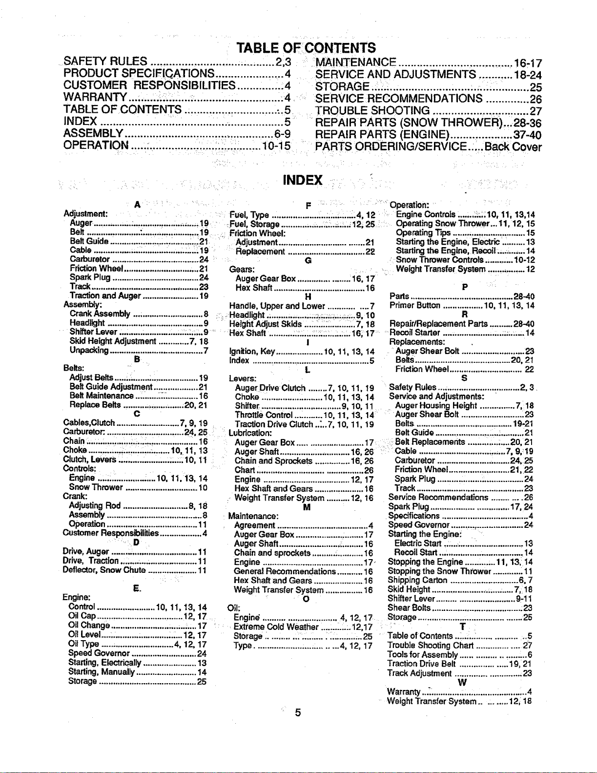
TABLE OFCONTENTS
SAFETY RULES ........................................ 2,3
PRODUCT SPECIFICATIONS ...................... 4
CUSTOMER RESPONSIBILITIES ............ ._4
WARRANTY.... ............................................. .4
TABLE OF CONTENTS .............................. -.5
INDEX ......................................... .................. 5
ASSEMBLY ................................................ 6-9
OPERATION .......................................... 10-15
MAINTENANCE ........................ 16-17
SERVICE AND ADJUSTMENTS ........... 18-24
STORAGE ................................................... 25
SERVICE RECOMMENDATIONS .............. 26
TROUBLE SHOOTING ............................... 27
REPA! RPARTS (SNOW TH ROWER)...28-36
REPAIR PARTS (ENGINE} .................... 37-40
PARTS ORDERING/SERVICE..... Back Cover
INDEX
A
Adjustment:
Auger ................ :................. ;.......... 19 •
Belt ...................... .:....................... 19
o
Belt Guide ......................... :21
Cable .................... ;........................ 19 :
Carburetor ..................................... 24
Fdctbn Wheel ................................ 2t
Spark Plug..................................... 24
Track.............................................. 23
Tractionand Auger ........................ lg
Assembly:
F Operation:
Fuel, Type .................... ,......;.......4, 12 Engine Controls.......;L'.;10, 11, 13,14
Fuel, Storage ............... ...:;:..;,;..: 12, 25 _ Operating Snow Thrower...11, 12, 15
FrictionWheel: Operating Tips............................... 15
Adjustment.................................... 21 Starting the Engine, Electric .:........ 13
Replacement ................................. 22 Starting the Engine, Reoofl....L...... 14
G : Snow ThrowerControls ......... ;..10-12
Geam: Weight Transfer System ................ 12
AugerGear Box ...................... 16, 17
Hex Shaft ....................................... 16
H
Handle, Upper and Lower ................ 7
CrankAssembly ... ........................... 8 :::;.Headlight.; .......;.......;;;;;_.:.;_;:.;.;;;;.9. I0
Headlight ......................................... 9 " Height Adjust Skids ::::::::::::::::::::::: t8
ShifterLever ,.; ......;..........;;..;.:;.:;;;.9 ....... Hex Shaft. ......... :::;:.:.:.:::::::..:.:,.16, 17.....
Skid HeightAdjustment ............. 7, 18 I
Unpacking........................................ 7
e ,
Belts:
Adjust Belts.....;:_.......;.:,................. 19
BeltGuide Adjustment................... 21
Belt Maintenance..: .......::::............. 16
Replace Belts .......................... ;20, 21
C
Cables,Clutch ........................... 7, 9, lg
Carburetor:.................................. 24,25 :: :
Ignition, Key.................... 10, 11, 13, 14
index ........_......................................... 5
L
Levers:
AugerDrive clutch ........7, 10, 11, 19
Choke ,. .............. ......... 10, 11, 13, 14
Sh_e_ ................................. 9, 10, 11
Throttle Control ...:........ 10, 11, 13, 14
TractionDrive Clutch..:..7, 10, 11, 19
Lubrication:
P
Parts............................................ 28-40
Primer Button................. 10, 11, 13, 14
R
Repair/Replacement Parts .......... 28-40
Recoil Starter ...................... ;...:;....... 14
Replacements:
Auger Shear Bolt ....i...................... 23
Belts......................................... 20, 21
FrictionWheel ............................... 22
S
Safety Rules.:.. ............................... 2, 3.
Service and Adjustments:
Auger Housing Height ............... 7, 18
•Auger Shear Bolt........................... 23
Belts ......................................... 19-21
Belt Guide....................... L..;......... .21
Chain _....:.:........... ;:,:::..:..: 16 •
Choke........;::::::::;:::::::;:::::....... I0,. 1I, 13
Clutch, Levers .......... :.......... ;;;.;;.10, 11
Controls:
Engine .:.:L._............LI" 10, 11,13, I4
Snow Thrower ............................... IO
Crank:
AdjustingRod ............................ 8, 18
Assembly......................................... 8
Operation....................................... 11
Customer Responsibilities.................. 4
Drive, Auger ........_............................ 11
Drive, Traction.;:,...... .................... 11
Deflector,Snow Chute ..................... 11
E.
Engine:
Control......................... 10, 11, 13, 14
Oil Cap ..................................... 12, 17
Oil Change ............................. ..,.. 17
Oil Level.....: .......... ;............:.:... 12, 17
Oil Type ............................... 4, 12, 17
Speed Governor ............................ 24
Starting,Electrically....................... 13
Starting,Manually .......................... 14
Storage.......................................... 25
Auger Gear Box............................ 17: :::i:Belt Replacements .......... ...;....20, 21
Auger Shaft ............... ;.............. 16, 26 Cable .............................. ...,.. 7, 9,_19
Chain and Sprockets ............... 16, 26 Carburetor ............................... 24,25
Chart. ............................................ 26 FrictionWheel.......................... 21, 22
Engine ..................................... 12, 17 Spark Plug ..........:;......................... 24
Hax Shaft and Gears ..................... 16 Track .............................................. 23
: WeightTransfer System .......... 12, t6 Service Recommendations ............ 26
M : Spark Plug................................. 17,24
Maintenance: Specifications ..................................... 4
Agreement ....................................... 4 Speed Governor ........._,.................... 24
Auger Gear Box ................... .......... 17 Startingthe Engine:
Auger Shaft ......................... , ......... 16 Electric Start .._........._.................... 13
Chain and sprockets.......... _........... 16 ReCoilStart ...;................................ 14
Engine .................................. .........17- Stoppingthe Engine .......... ;..11, 13,14
General Recommendations........... 16 Stopping the Snow Thlower ............ .11
Hex Shaftand Gears ..................... 16 Shipping Carton ............................. 6, 7
Weight Transfer System ................ 16 Skid Height.........................;..........7, 18
• O Shifter Lever................................. 9-11
Oil: Shear Bolts...................................... :23
Engine ................................ 4, 12, 17 Storage............................................ 25
Extreme Cold Weather ......._...:.12,17 _ T
Storage :..... ..... .i.L._ .... _.........,..25 Table ofContents ..:..;.._................. ..5
Type.................................. 4, 12, 17 TroubleShootingChart .................... 27
Tools for Assembly....................... ._6
TractionDrive Belt .................... 19,21
Track Adjustment............................ 23
w
Warranty..;.. ......:.....;.............. :.........:_4
WeightTransfer System .......... 12,_18
,, ,,, LI i i
MBLY
i ii i H i, ,,, , •
THIS SNOW THROWER ISEQUIPPED WITH "TRAC-PLUS" AND ONLY
MOVES EFFECTIVELY WHEN ENGINE IS RUNNING
i
ffyoursnowthrower must be moved withoutthe aid of theengine, it willbe easier to pullthe snowthrower back-
wardbythe handles, ratherthan pushing.
OnstartUp,the trackdrive system may betightand wniloosenup as the _ow thrower isused. Alterfirstuse,
checkthe trackfor tension and adjustifnecessary.See the Track Adjustmentparagraph in theService and Adjust-
mentssectionof this manual. Check trackadjustmentand fasteners regularly.
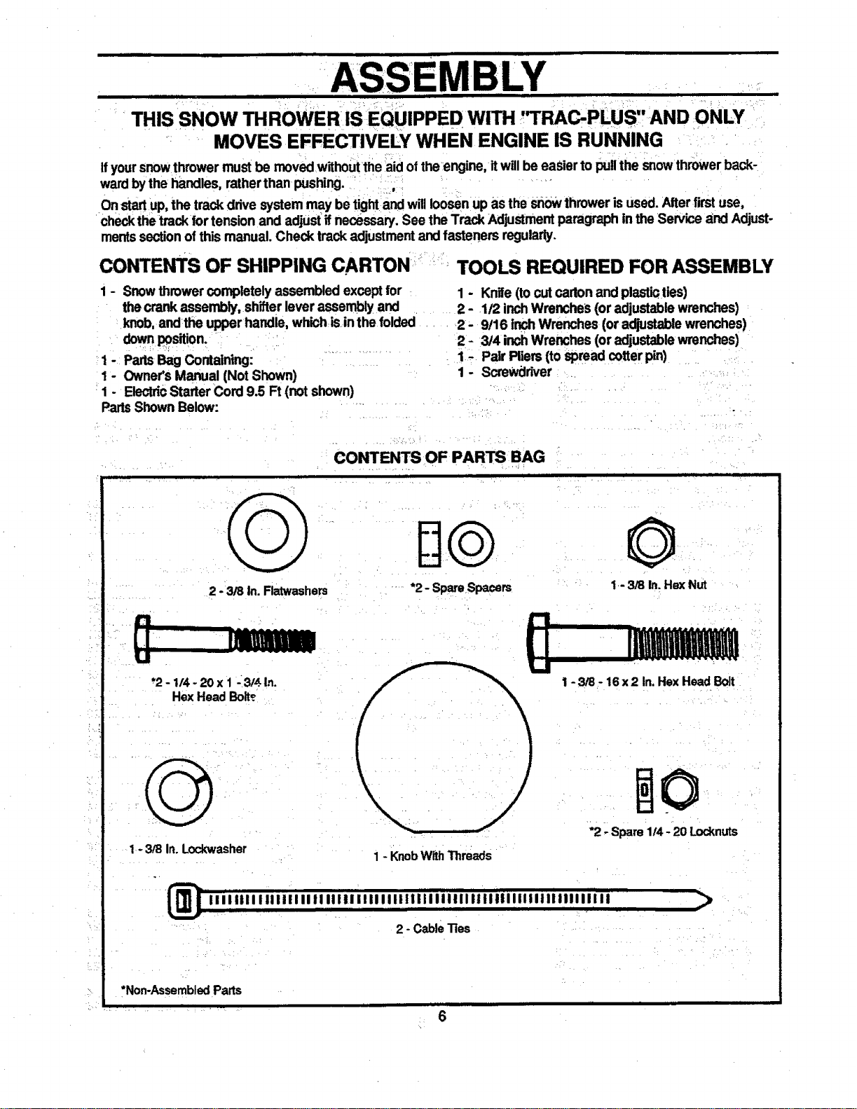
CONTE_S OF SHIPPING CARTON r,' TOOLS REQUIRED FOR ASSEMBLY
1-
PartsShownBelow:
1 - Snow throwercompletely assembledexcept for
thecrank assembly, shifterlever assembly and
knob, andrtheupper handle, whichis inthe folded
downposition.
PartsBag Containing:
Owner'sManual (Not Shown)
ElectdcStarter Cord 9.5 Ft (not shown)
1 - Knife (tocut cartonand plastiaties)
2 - 1/2 inchWrenches (or adjustablewrenches)
2- 9!16 inchWrenches (or adjustablewrenches)
2- 3/4 inchWrenches (or adjustablewrenches)
1. Pair Pliers(tospread cotter pin)
1- ScreWdriver
2 - 3/8 in. Flatwashers
"2- 1t4-20x 1_3!,$ In.
Hex Head Boit_
1-3/8 In. Lockwasher
CONTENTS OF PARTSBAG
ii , i |
*2 - Spare Spacers
II
1 - KnobWithThreads
©
1-3/8 In. Hex Nut
1-3/8 - 16x2 In.Hex Head Bolt
*2 - Spare 1/4 - 20 Locknuts
2 - Cablelies
>
*Non-Assembled Parts
6

FigureI showsthesnowthrowerintheshippingposition.
Figure2 showsthesnowthrowercompletely assembled.
Reference to the right and left hand side of the sndw
thrower isfrom the operator'spositionat the handle.
TO REMOVE SNOW THROWER
FROM CARTON (See Fig 1)
• Removetop pallet and discard.
• Cut allfour comers ofthe cartonfrom topto bottom
and laythe panelsfiat.
• Cut the cable ties attached tothe auger.
• Cutanddiscardtheplastictiesthatsecurethecrank
assemblyand place the assemblyaside.
• Removethepackingmaterialfromthe controlpanel.
• Cut and discard the packing securing the clutch
cablesto the lowerhandle.
With two 9t16 inch wrenches, loosen (do not
remove) both bolts securingthe upper and lower
handles. Swingthe upperhandle intotheoperating
position.
NOTE: ifthecables havebecome disconnectedfromthe
clutchlevers,reinstallthe cables as shown in Figure3.
• Tightenbothboltssecurely.
Rollthe snowthroweroffthe skid by pullingonthe
handle.
NOTE: This snowthrowerisequipped with a trackdrive
and canbe hardto pushwhen the engine is notrunning.
Itiseasierto pullthe snowthrower backwardifitmustbe
moved withoutthe engine running.
The drive system may be tightwhen you firstuse your
snowthrower. Itloosensup as you use it.
HOW TO SET UP YOUR SNOW
THROWER
• Forpacking,the heightadjustskidswere mounted
with the bottom lip tumed inward. Remove skid
mounting nuts (Fig. 2) and remount withthe lip
outward.
To adjusttheskidheightfordifferent conditions,see
To AdjustSkidsHeights paragraph on page 18.
CAUTION: IF YOU ARE REMOVING
A SNOW FROM ANY ROCKY OR UNEVEN
SURFACES, RAISE THE FRONT OF THE
SNOW THROWER BY MOVING THE
SKIDS DOWN. THIS WILL HELP TO PREVENT
ROCKS AND OTHER DEBRIS FROM BEING
PICKED UP AND THROWN BY THE AUGER.
LOWER HANDLE
CRANK
CLUTCH
CABLE
FIG. 1
UPPER
HANDLE
. ASSEMBLY
FIG. 2
im i
DRIVE
LEVER
FIG. 3
7
BLY
I ] I i il IIIII mR ii
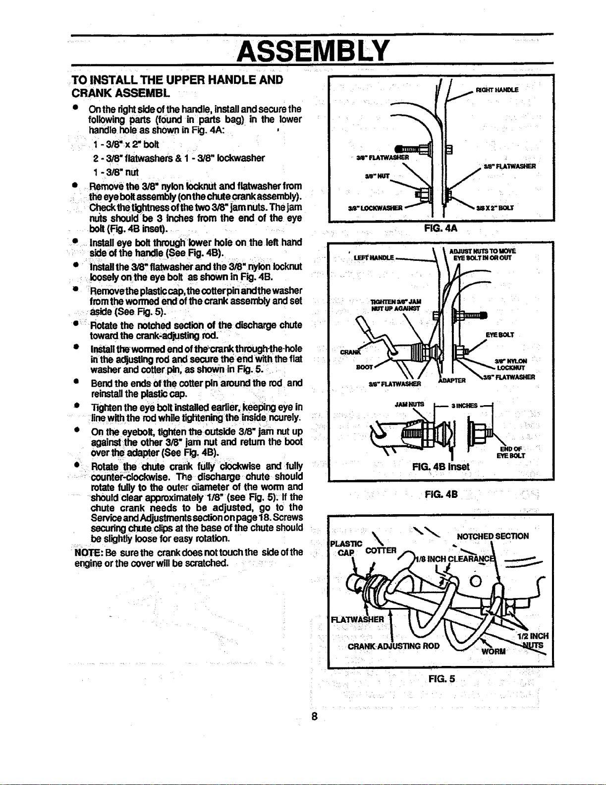
TO INSTALL THE UPPER HANDLE AND
CRANK ASSEMBL
Onthe rightsideofthe handle,installand securethe
following parts (found in parts bag) in the lower
handle holeas shownin Fig. 4A:
1 - 3/8"x 2, bolt
2 - 3/8" flatwashers& 1 - 3/8" iockwasher
1 - 3/8" nut
• Removethe 3/8" nylonlocknut and flatwasherfrom
theeyebolt assembly(onthechute crankassembly).
thetightnessofthe two3/8" jamnuts.Thejam
nu_sshouldbe 3 inches from the end of the eye
bolt(RD,4B inset).
• Installeye bolt throughlower hole on the lefthand
sideof the handle (See Rg. 4B).
• Installthe 3/8" flatwasherand the 3/8" nylon Iocknut
looselyon the eye bolt as shown in Fig. 4B.
• _Rernovetheplasticcap,thecotterpin andthewasher
fromthe wormedendof thecrank assembly andset
aside (See Fig. 5).
o_: Rotate the notched sectionof the dischargechute
towardthe crank-adjustingrod.
• InStallthewommd end ofthe-crankthrough-the-hole
inthe adjustingrod and secure theend with thefiat
washer and cotterpin, as shownin Fig. 5.
• Bendthe ends ofthe cotter pin aroundthe rod and
reinstallthe plasticcap.
• Tightenthe eye boltinstalledearlier,keeping eye in
linewiththe rod whiletighteningthe insidencure]y.
• Onthe eyebolt, tightentheoutside 3/8" jam nutup
agalnst_theother 3/8" jam nut and retum the boot
over the adapter(See Fig. 4B).
• Rotate the chute crank fully clockwise and fully
counter,clockwise. The discharge chute should
rotatefully to the outer diameter of the worm and
shouldclear approximately1/8" (see Fig. 5). If the
chute crank needs to be adjusted, go to the
ServiceandAdjustmentssectionon page 18.Screws
securingchuteclips at the base ofthe chute should
be slightlyloosefor easy rotation.
NOTE: Be surethe crankdoes nottouchthe sideofthe
engineorthe coverwillbe scratched.
i
_- RLAIWASHB_
I_OHT HANOLE
/
H
FIG. 4A
AO.IUSl"NUTSTO M(W_
gi OROUT
EYEBOLT
I ENOOF
Bile BOLT
FIG. 4B Inset
ii ii iii
FIG. 4B
RG. 5
8
, ,,ll j m Jl_q .||.n i i i i i n n, , ...........................
MBLY
III II IIIItl III lilt lilt III t t //i i i
TO INSTALL HEADLIGHT
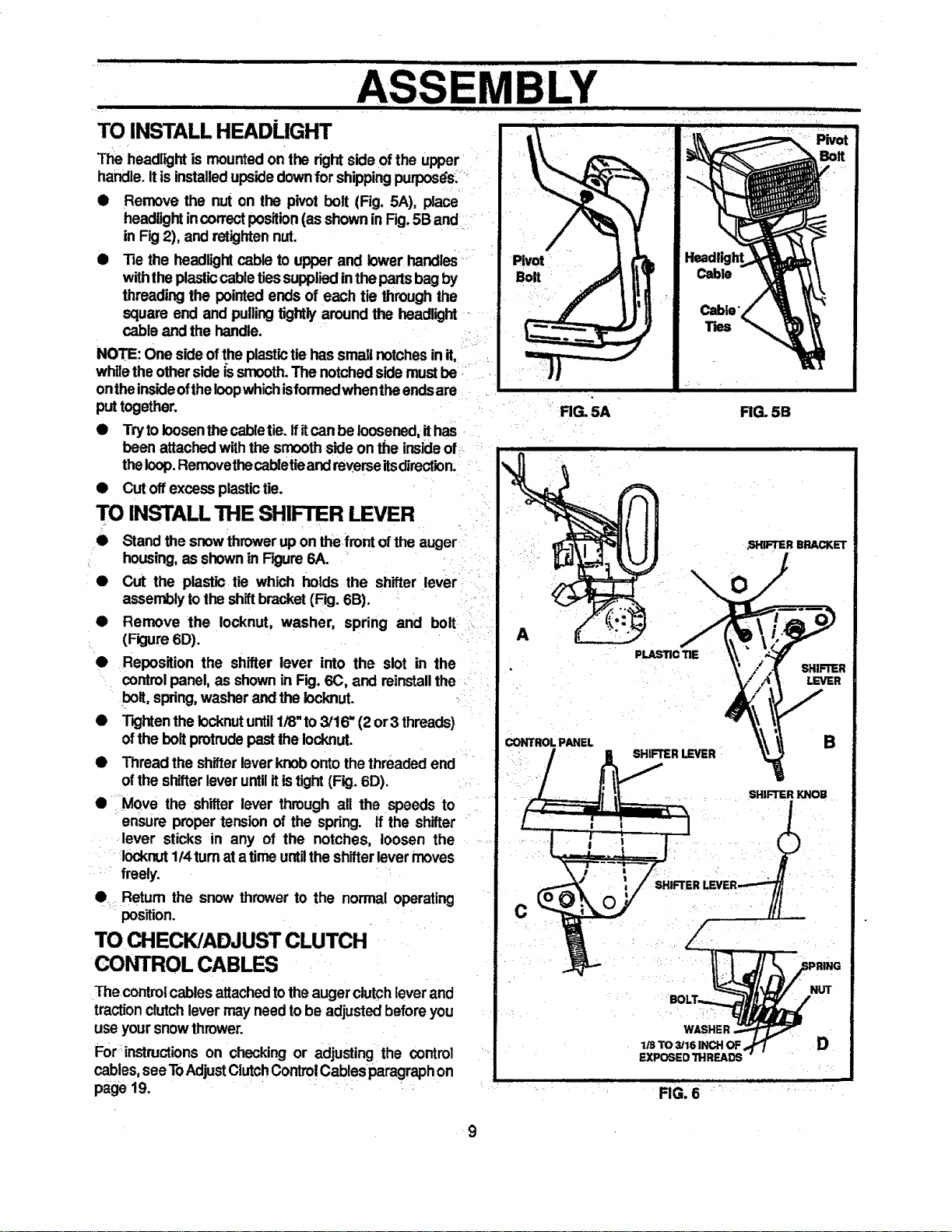
The headlightis mountedon the right side ofthe upper '
handle.Itis installedupsidedownfor shippingpurposdst'_
• Remove the nut on the pivot bolt (Fig, 5A), place
headlightincorrectposition(as showninFig.5B and
in Fig2), and retightennut.
• Tie the headlightcable to upper and lowerhandles
withtheplasticcabletiessuppliedinthe partsbagby
threading the pointed ends of each tie throughthe
square end and pullingtightlyaround the headlight -
cable and the handle.
NOTE: One sideofthe plastictiehas small notchesin it,
whilethe otherside is smooth.The notchedsidemustbe
ontheinsideofthe Ioopwhichisformedwhentha endsare
put together,
• Tryto loosenthecabletie. ffitcanbe loosened,ithas
been attachedwiththe smoothsideon the insideof_:
theloop.Removethecabletieandreverseitsdirection.
• Cut offexcess plastictie.
TO INSTALL THE SHIFTER LEVER
Stand the snowthrower up on the,frontofthe auger
_ housing,as shownin Figure6A.
• Cut the plastic tie which holds the shifter lever
assemblytothe shiftbracket(Fig. 6B).
• Remove the Iocknut, washer, spring and bolt
(Fkjure6D).
• ReposiUonthe shifterleverintothe slotinthe
controlpanel,as shown inFig.6(3,and reinstallthe
bolt,spring,washerand thelocknut.
• TightenthelocknutuntilI/8"to3/16"(2or3 threads)
oftheboltprotrudepastthelocknut.
• Thread the shifterleverknobonto thethreaded end
ofthe shifterleveruntilitistight(Fig. 6D).
• Move the shitter lever through all the speeds to
ensure proper tension of the spring, tf the shifter
lever sticks in any of the notches, loosen the
Iocknut1t4turnatatime untgthe shifterlevermoves
freely.
e: Return the snow thrower to the normal operating
position.
TO CHECK/ADJUST CLUTCH
CONTROL CABLES
The contro!cables attachedtotheaugerclutchleverand
tractionclutchlever may needtobe adjustedbeforeyou
use yoursnow thrower.
Fort:instructionson checking or adjusting=the control
cables,see ToAdjustClutchControlCablesparagraphon
page 19.
RG. 5A FIG. 5B
r
A
PLASTICTIE
CONTROL PANEL
C
WASHER
1/S TO 3/16 INCH OF
EXPOSED THREADS
FIG. 6
SHmTER
LEVER
B
SHIFTER KNOB
D
9
• ii1•11 i i • i
........,................, OPERATION
THROWER .......
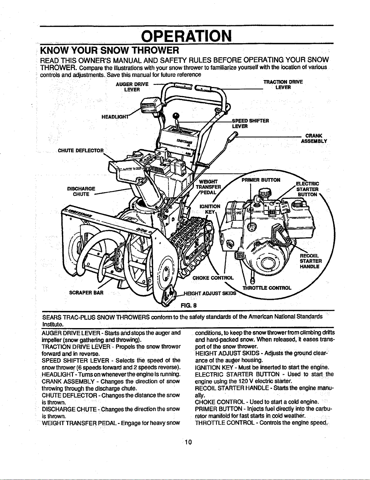
KNOWYOUR:SNOW
READ THIS OWNER'S MANUAL AND SAFETY RULES BEFORE OPERATING YOUR SNOW
TH ROWER. Compare the illustrationswith your snowthrowertofamiliarize yourselfwith the location of vadous
controls and adjustments. 'Save this manual for future r_emn_
AUGER DRIVE TRACTION DRIVE
.... i LEVER LEVER
LEVER
...... . CHUTE DEFLECTOR :
DISCHARGE
CHUTE
WBGHT
TRANSFER
IGNITION
KEY
PRIMER BUTTON
BUTTON
REOOIIL
STARTER
HANDLE
CHOKE CONTROL
SCRAPER BAR
THROTTLE CONTROL
FIG. 8
I IIJIItUI I • I I 111111111 I
SEARS TRAC-PLUS SNOWTHROWERS conformtothe safety standardsof the American NationalStandards
Institute. L _ .......
ii LIL
AUGER DRIVE LEVER - Startsandstopsthe augerand
impeller(snowgathering andthrowing).
TRACTION DRIVE LEVER - Propelsthe snow thrower
forwardand in reverse.
SPEED SHIFTER LEVER - Selects the speed of the
snowthrower(6 speeds forwardand 2 speeds reverse).
HEADLIGHT -Turns onwheneverthe engineisrunning.
CRANK ASSEMBLY - Changes the directionof snow
throwingthroughthedischargechute.
CHUTE DEFLECTOR - Changesthe distancethe snow
isthrown. :
• DISCHARGE CHUTE :Changes the direction the snow
is thrown.
" WEIGHTTRANSFER PEDAL- Engage for heavy snow
i i iron f i
conditions, to keepthesnowthrowerfromclimbing drifts
and hard-packedsnow. When released, iteases trans-
portofthe snowthrower.
HEIGHT ADJUST SKIDS - Adjuststhegroundclear-
ance ofthe auger housing.
IGNITION KEY- Mustbe insertedto start the engine.
ELECTRIC STARTER BUTTON - Used to start;the
engine usingthe 120 V electricstarter.
RECOIL STARTER HANDLE - Startstheengine manu-
ally. *
CHOKE CONTROL - Used to start a cold engine.
PRIMER BUTTON - Injectsfuel directlyintothe carbu-
retormanifoldfor fast startsin cold weather.
THRO'I-rLE CONTROL - Controlsthe enginespeed,
10
H
i |11 i ui , i1| iii iii i
• OPERATION
lUL III1"I........
The operationofanysnowthrowercanresultinforeign objectsbeingthrown intothe
eyes, which can resultinsevere eye damage. Alwayswear safety glasses or eye
shieldswhile operatingthe:snow thrower.
We recommend standardsafety glasses or wide visionsafety mask for over your
glasses available at SEARS Retail or Catalog Stores.
HOW TO USE YOUR SNOW
THROWER
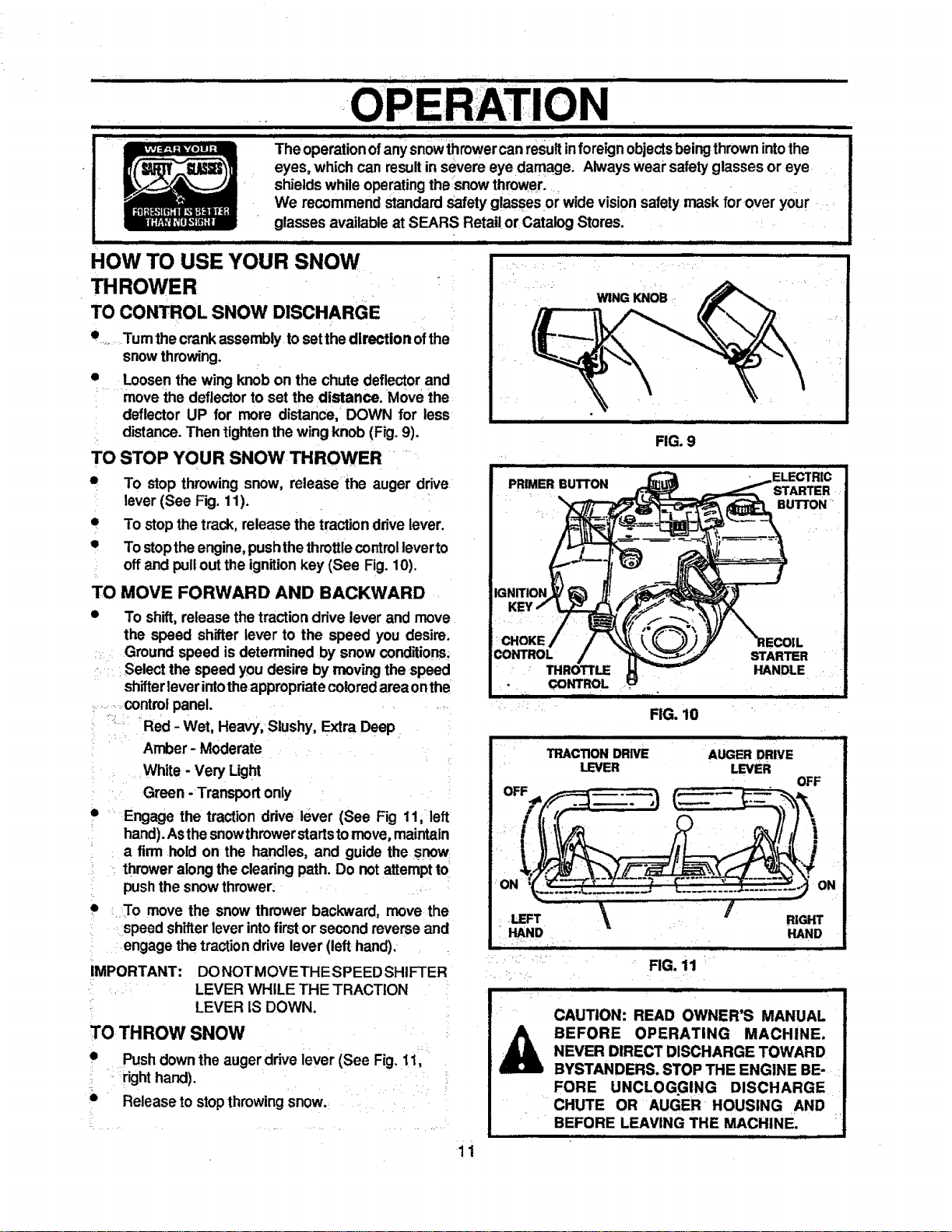
TO CONTROL SNOW DISCHARGE
Tum thecrank assembly tosetthedirection ofthe
snowthrowing.
e
Loosenthe wing knobon the chute deflectorand
.... movethe deflectorto set the distance. Move the
deflector UP for more distance, DOWN for less
distance. Then tightenthe wing knob (Fig. 9).
TO STOP YOUR SNOW THROWER
• To stop throwing snow, release the auger drive
lever (See Fig. 11).
• To stopthe track, release the traction drivelever.
• To stoptheengine,pushthethrottlecontrol leverto
: offand pullout the ignitionkey (See Fig. 10).
TO MOVE FORWARD AND BACKWARD
• To shift,release thetraction drive lever and move
the speed shifter lever to the speed you desire.
Ground speed isdetermined by snow conditions;
= Select the speed you desire by movingthe speed
shifterleverintotheappropriatecoloredareaonthe
...........controlpanel. =
,-°, , = ,
'.... Red - Wet, Heavy; Slushy, Extra Deep
Amber - Moderate
White - Very Light
= Green -Transport only
. Engage the tractionddve lever (See Fig 11, left
• hand).Asthesnowthrowerstartstomove,maintain
a firm hold on the handles, and guide the snow
, : thrower alongthe clearing path. Do not attemptto
push the snowthrower;
i
• . To move the snow thrower backward, move the
speed shifterleverintofirstor secondreverse and
engage thetractiondrive lever (left hand).
IMPORTANT: DONOTMOVETHESPEED SHIFTER
. . LEVER WHILE THE TRACTION
LEVER IS DOWN.
TO THROW SNOW
• Pushdownthe augerdrive lever (See Fig. 11,
: . right hand).
°
• Release to stopthrowingsnow.
[
WING KNOB
FIG, 10
i JLWULI = I I 1_
TRACTION DRIVE AUGER DRIVE
LEVER LEVER
OFF
ON ON
.LEFT _ RIGHT
HAND HAND
iii r • ii
FIG. 11
CAUTION: READ OWNER'S MANUAL
BEFORE OPERATING MACHINE.
NEVER DIRECT DISCHARGE TOWARD
BYSTANDERS. STOP THE ENGINE BE-
FORE UNCLOGGING DISCHARGE
CHUTE OR AUGER HOUSING AND
BEFORE LEAVING THE MACHINE,
11
! • • , ,, ,-,, , i,ii i , , , , ,
OPERATION
. i1.11 Hi| i = i
° .
i
HANDLE
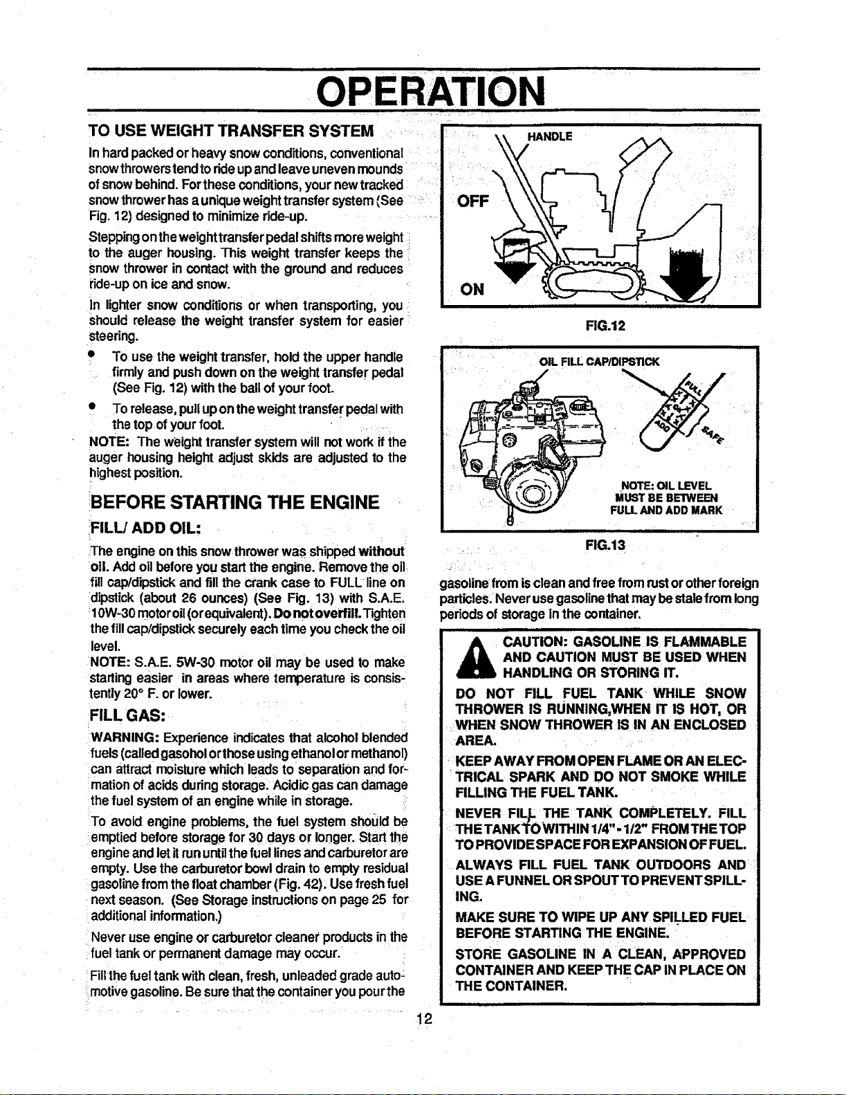
TO USE WEIGHT TRANSFER SYSTEM
In hardpackedor heavysnow conditions,conventional
snowthrowerstendtorideupandleave unevenmounds
ofsnowbehind. Forthese conditions, yournewtracked
snowthrowerhasa uniqueweighttransfer system(See '_
Fig. 12) designedto minimize ride-up.
Steppingontheweighttransferpedalshiftsmoreweight
to the auger housing.This weight transfer keeps the
snow thrower in contact with the ground and reduces
ride-upon iceand snow.
in lighter snow conditionsor when transporting, you
Shouldrelease the weight transfer system for easier
steering.
• To use theweighttransfer,holdthe upperhandle
firmlyand pushdown on theweighttransferpedal
(SeeFig.12)withtheballofyourfoot.
• To release,pullupontheweighttransferpedalwith
thetopofyourfoot.
NOTE: The weighttransfersystemwillnotwork ifthe
augerhousingheightadjustskidsareadjustedtothe
highestposition.
!BEFORE STARTING THE ENGINE
FILL/ADD OIL:
The engineon thissnow throwerwas shippedwithout
oil. Addoilbeforeyou startthe engine. Remove the oil
fillcap/dipstickand fill the crank case to FULL lineon
dipstick (about 26 ounces) (See Fig. 13) with S.A.E.
_10W-30motoroil(orequivalent).Do notoverfULTighten
thefillcap/dipsticksecurelyeach timeyou checkthe oil
level.
NOTE: S.A.E. 5W-30 motor oil may be used to make
starling easier in areas where temperature is consis-
tently20° F. or lower.
FILL GAS:
WARNING: Experience indicatesthat alcohol blended
fuels(calledgasoholorthose usingethanolor methanol)
can attract moisturewhich leadsto separationand for-
marion ofacids during storage. Acidicgas candamage
thefuel system of an enginewhile in storage.
To avoid engine problems,the fuel system shouldbe
emptiedbefore storagefor 30 days or longer. Startthe
engineand letitrununtilthefuel linesand carburetorare
empty. Use the carburetorbowldrain to emptyresidual
gasoline from thefloatchamber (Fig. 42), Usefresh fuel
nextseason. (See Storageinstructionson page 25 for
additionalinformation.)
Never use engineor carburetorcleane_'productsinthe
fuel tankor permanent damage may occur. !
Filtthefuel tankwithclean,fresh, unleadedgradeauto:
:motive gasoline.Besurethatthecontainer you pourthe
t2
OFF
ON
i
FIG.12
OIL FILL CAWDIF_STICK
NOTE: OIL LEVEL
MUST BE BETWEEN
FULL AND ADD MARK
| i
RG.13
gasolinefrom isclean andfree fromrustor otherforeign
)articles.Neverusegasolinethatmay bestale from long
)eriodsof storage in the container,
i i i H
A CAUTION: GASOLINE IS FLAMMABLE
AND CAUTION MUST BE USED WHEN
HANDLING OR STORING IT.
DO NOT RLL FUEL TANK WHILE SNOW
THROWER IS RUNNING,WHEN IT IS HOT, OR
WHEN SNOW THROWER IS IN AN ENCLOSED
AREA.
KEEP AWAY FROM OPEN FLAME OR AN ELEC-
TRICAL SPARK AND DO NOT SMOKE WHILE
RLLING THE FUEL TANK.
NEVER FILL THE TANK COMPLETELY. FILL
THE TANKTOWITHIN 1/4 '- 112"FROMTHE TOP
TO PROVIDE SPACE FOR EXPANSION OF FUEL.
i ALWAYS FILL FUEL TANK OUTDOORS AND
USE A FUNNEL ORSPOUT TO PREVENT SPILL-
ING.
MAKE SURE TO WIPE UP ANY SPILLED FUEL
BEFORE STARTING THE ENGINE.
STORE GASOLINE IN A CLEAN, APPROVED
CONTAINER AND KEEP THE CAP IN PLACE ON
THE CONTAINER.
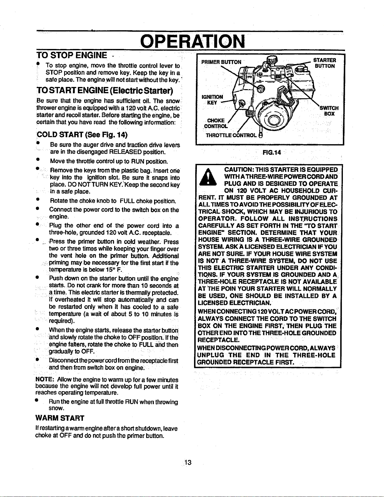
TO STOP ENGINE
uw]_wl i i
PRIMER BUTTON
• To stop engine, move the throttle control lever to
STOP positionand remove key, Keep the key in a
safe place.The enginewill notstartwithoutthe key."
TO START ENGINE (Electric Starter)
Be sure that the engine has sufficient oil. The snow,
thrower engine isequippedwith a 120 voltA.C. electdc =
starter and recoilstarter. Beforestartingthe engine,be
certainthat you have read the followinginformation:
COLD START (See Fig. 14)
s Be sure the auger drive and traction drivelevers
are in the disengaged RELEASED position.
• Move the throttlecontrol up to RUN position.
• Remove the keys fromthe plasticbag. Insert one
key into the ignitionslot=Be sure it Snaps into
place. DO NOT TURN KEY.='Keepthe secondkey
in a safe place.
• Rotate the choke knobtO FULL choke position.
• Connect the powercordto the switchbox onthe
engine.
• Plug the other end of the power cord into a
three.h01e,grounded120 volt A.C. receptacle.
• ._ .P_ressthe primer button in cold weather. Press
two or three timeswhile keeping your fingerover
the vent hole on the primer button. Additional
priming may be necessary for the firststartif the
temperature is below 15° F.
• Push down on the starterbutton until the engine
starts. Do notcrank for more than 10 seconds at
atime. This electricstarter isthermallyprotected.
If overheated it will stop automatically and can
be restarted only when it has cooled to a safe
temperature (a wait of about 5 to 10 minutes=is
required).
• When the enginestarts,release the starter button
and slowlyrotatethe choketo OFFpositlon. ifthe
enginefalters, rotatethe choke to FULL and then
graduallyto OFF. •
• Disconnectthepowercordfrom thereceptaclefirst
and then fromswitchbox on engine:
IGNITION
KEY
CHOKE
CONTROL
THROTTLE CONTROL
nnnunnn|ul
FIG.14
mnn
n u,__
STARTER
BUTTON
BOX
,,,,,, ,,, • i
CAUTION: THIS STARTER IS EQUIPPED
WITH ATHREE-WIRE POWER CORD AND
PLUG AND IS DESIGNED TO OPERATE
ON 120 VOLT AC HOUSEHOLD CUR-
RENT. IT MUST BEPROPERLY GROUNDED AT
ALLTIMES TOAVOID THE POSSIBILITY OF ELEC=
TRICALSHOCK, WHICH MAY BE INJURIOUS TO
OPERATOR. FOLLOW ALL INST.RUCTIONS
CAREFULLY AS SET FORTH IN THE "TO START
ENGINE" SECTION. DETERMINE THAT YOUR
HOUSE WIRING IS A THREE-WIRE GROUNDED _
SYSTEM. ASK A LICENSED ELECTRICIAN IF YOU
ARE NOT SURE. IF YOUR HOUSE WIRE SYSTEM
IS NOTA THREE-WIRE SYSTEM, DO NOT USE
THIS ELECTRIC STARTER UNDER ANY CONDI-
TIQNS. IF YOUR SYSTEM IS GROUNDED AND A
THREE-HOLE RECEPTACLE IS NOT AVAILABLE
AT THE POIN YOUR STARTER WILL NORMALLY
BE USED, ONE SHOULD BE INSTALLED BY A
LICENSED ELECTRICIAN,
WHEN CONNECTING 120VOLTAC POWER CORD,
ALWAYS CONNECT THE CORD TO THE SWITCH
BOX ON THE ENGINE FIRST, THEN PLUG THE
OTHEREND INTO THE THREE-HOLE GROUNDED
RECEPTACLF--
WHEN DISCONNECTING POWER CORD, ALWAYS
UNPLUG THE END IN THE THREE-HOLE
GROUNDED RECEPTACLE FIRST.
i i
NOTE: Allowthe enginetowarm up for a few minutes
because the engine will not develop full power until it
reaches operatingtemperature.
• Runthe engineatfullthrottleRUN whenthrowing
snow.
WARM START
Ifrestartingawarm engineaftera shortshutdown,leave
choke at OFF and do notpush the primer button.
13
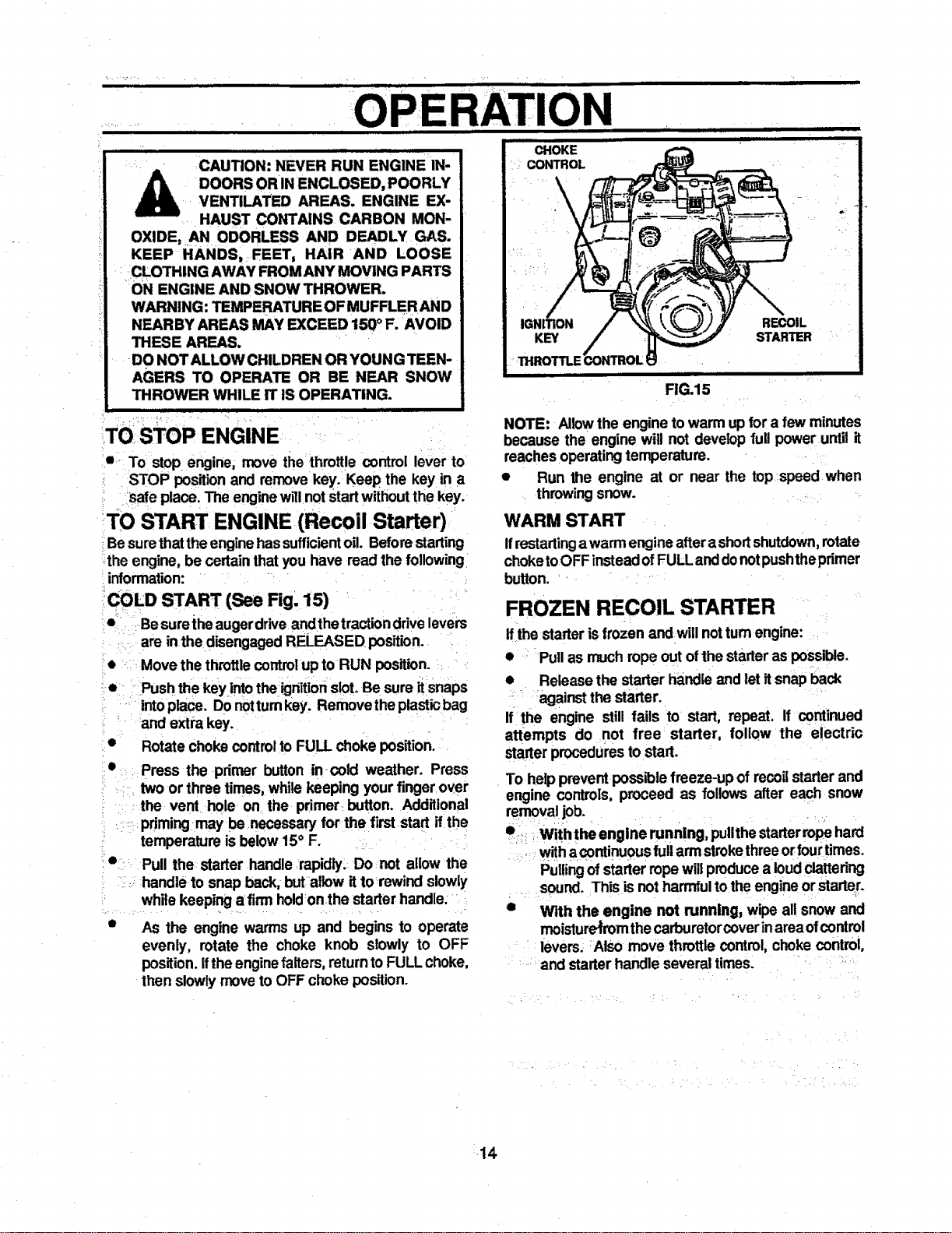
CAUTION: NEVER RUN ENGINE IN-
A DOORS ORIN ENCLOSED, POORLY
VENTILATED AREAS. ENGINE EX-
HAUST CONTAINS CARBON MON-
OXIDE, AN ODORLESS AND DEADLY GAS.
KEEP HANDS, FEET, HAIR AND LOOSE
CLOTHING AWAY FROM ANY MOVING PARTS
ON ENGINE AND SNOW THROWER.
WARNING: TEMPERATURE OFMUFFLER AND
NEARBY AREAS MAY EXCEED 150° F. AVOID
THESE AREAS.
DO NOT ALLOW CHILDREN OR YOUNG TEEN-
AGERS TO OPERATE OR BE NEAR SNOW
THROWER WHILE IT IS OPERATING.
I I I I
RATION
,i,
CHOKE
CONTROL
rT(
• To stop engine; move the throttle control lever to
STOP positionand removekey. Keep the key in a
Safe place. The enginewillnot startwithoutthe key.
TO START ENGINE (Recoil Starter)
Besurethattheenginehassufficientoil. Beforestarting
-the engine, be certain that you have read the following
information:
COLD START (See Fig. 15)
• Besurethe augerdrive andthe tractionddve levers
are in the disengagedRELEASED position.
Move the throttlecontrolup to RUN position.
Push the key intothe ignitionslot.Be sure it snaps
intoplace. Donotturnkey. Removethe plasticbag
and extra key.
Rotate choke controlto FULL choke position.
Press the primer button in cold weather. Press
twoor three times, whilekeeping yourfinger over
the vent hole on the primer button. Additional
pdrningmay be .necessary for the firststart ifthe
temperature is below15° F.
Pull the starter handle rapidly, Do not allow the
....handle to snap back, but allow ittorewind slowly
while keeping a firm holdonthe starter handle:
As the engine warms up and begins to operate
evenly, rotate the choke knob slowly to OFF
position.Ifthe enginefalters,returnto FULL choke,
then slowlymoveto OFF choke position.
i illl
KEY
THROTTLE
FIG.15
RECOIL
STARTER
NOTE: Allowthe engine towarm upfor a few minutes
because the engine will not develop full power until it
reachesoperatingtemperature.
• Run the engine at or near the top speed when
throwing snow.
WARM START
Ifrestartingawarm engineaftera shortshutdown,rotate
choketoOFF insteadofFULL anddonotpushtheprimer
button.
FROZEN RECOIL STARTER
if the starter isfrozen and willnotturnengine:
• Pull as muchrope out ofthe Starteras possible.
• Release the starter handle and letitsnap back
• against the starter.
If the engine still fails to start, repeat. If continued
attempts do not free starter, foliQw the electric
starterproceduresto start.
To helpprevent possiblefreeze-up of recoilstarter and
engine controls, proceed as follows after each snow
removaljob.
• _ Withthe engine running, pullthestarterropehard
withacontinuouslull armstrokethreeorfourtimes.
Pullingof starterropewillproducea loudclattering
sound. This isnot harmfultothe engineor starter.
• With the engine not running, wipe all snow and
moisture_rom thecarburetorcoverinareaofcontrol
levers; Also move throttle control, choke control,
and starterhandle several times.
ill LJ i Illll I
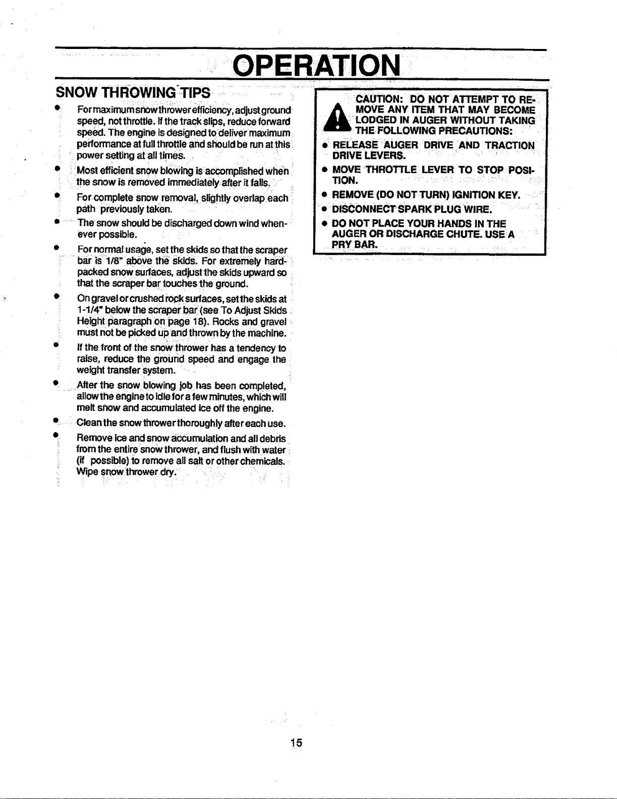
SNOW THROWING:TIPS
e= Formaximum Snowthrowerefficiency,adjustground
speed, notthrottle.Ifthe trackslips,reduceforward
speed.The engineisdesignedtodelivermaximum
performanceat fullthrottleand shouldbe runatthis
power settingatall times;
• Most efficientsnowblowingisaccomplished when
the snow is removed immediatelyafter itfalls.
• Forcomplete snow removal, slightlyoverlapeach
path previouslytaken.
The-snow shouldbedischargeddownwindwhen-
ever possible.
• F°r n°rmal usage,setthe skidssothatthescraper
bar is 118"above the skids. For extremely hard-
packed snow sudaces,adjustthe skidsupwardso
thatthe scraper bartouches the ground.
• Ongravelorcrushedrocksurfaces,settheskidsat
1-1/4" belowthescraper bar(see To Adjust Skids
Height paragraph Onpage18). Rocks and gravel
mustnotbe pickedupand thrownbythe machine.
• ifthe front ofthe snowthrower hasa tendencyto
raise, reduce the ground speed and engage the
weighttransfer system.
• Alter the snow blowing job has been completed,
allowthe enginetoidlefora few minutes, whichwill
meltsnow and accumulated ice offthe engine.
• .... Clean the snowthrowerthoroughlyaftereach use.
• Remove iceand snowaccumulationandall debris
fromthe entiresnowthrower, and flushwithwater
(if possible)to remove all saltor otherchemicals.
Wipe snowthrowerdry:
ii i • , ........
N •
i Jl
kllr
,= _CAUTION: DO NOT ATTEMPT TO RE-,
MOVE ANY ITEM THAT MAY BECOME
_ LODGED IN AUGER WITHOUT TAKING
_ THE,FOLLOWING PRECAUTIONS: "
• RELEASE rAUGER DRIVE AND TRACTION
DRIVE LEVERS. .... _ ' _
• MOVE THROTTLE LEVER TO STOP POSI-
"nON. : "_ •
• REMOVE (DO NOT TURN) IGNITION KEY. _
• DISCONNECTSPARK PLUG WIRE. _
• DO NOT PLACE YOUR HANDS IN THE
AUGER OR DISCHARGE CHUTE USEA
15
MAI E
GENE .....
RAL RECOMMENDATIONS
The warrantyonthis snowthrowerdoes notcoveritems
that have been subjected to operator abuse or negli-
gence.To receivefullvalue fromthe warranty, operator
mustmaintain snowthroweras instructedinthismanual
Some adjustmentswin need to be made periodicallyto
properlymaintain yoursnowthrower.
AlladjustmentsintheServiceand Adjustmentssectionof
this manualshouldbe checked atleast once each sea-
son.
AFTER FIRST USE : :- -
• Checkthetracksfortension andadjust_if_tieCessary
(See To Adjust Track paragraph on page 23).
Checkthetrackadjustment andfastenersregularly.
e Be surethat allfasteners are tight.
AS REQUIRED
The followingadjustments should be performed more
than once each season.
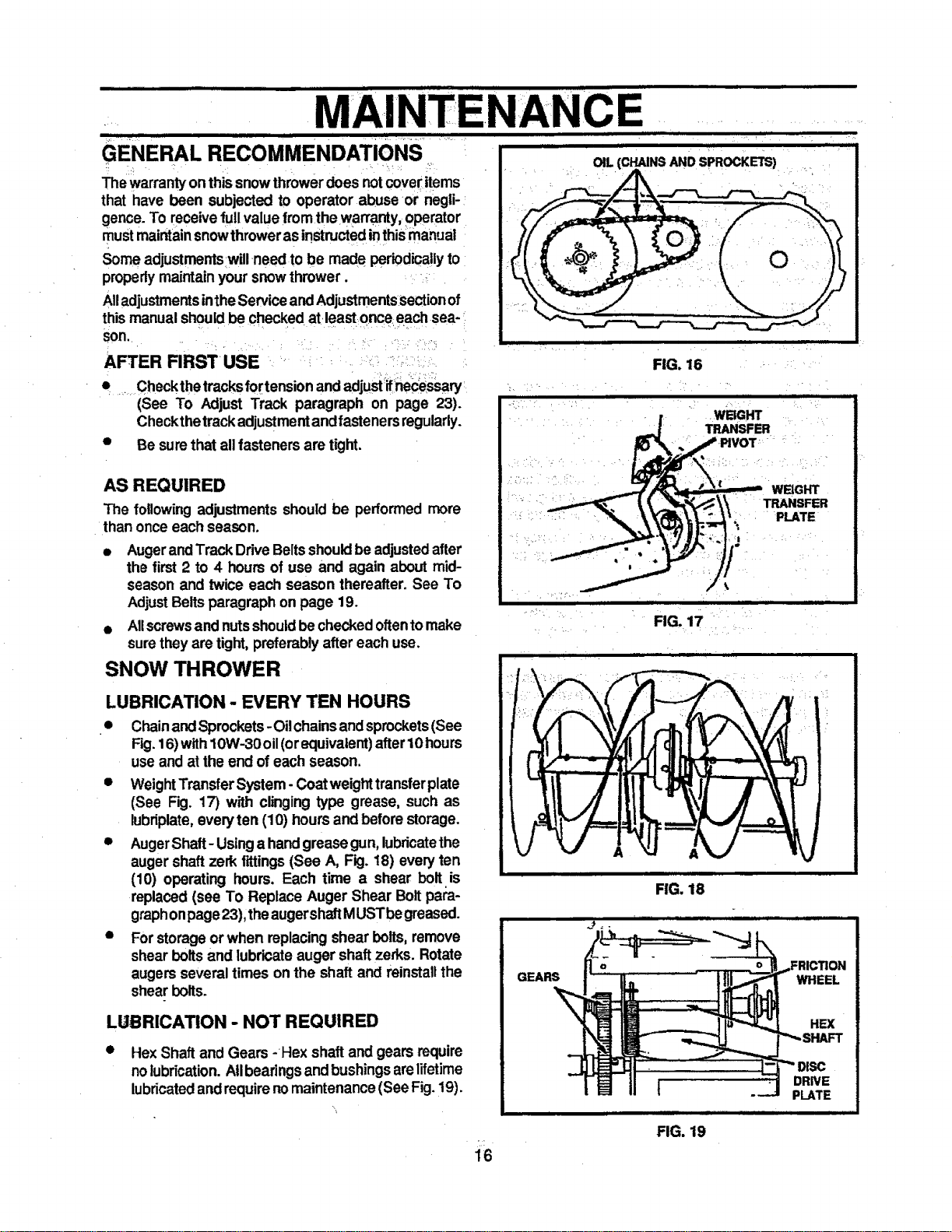
OIL (CHAINS AND SPROCKETS)
• • !
i i
e AugerandTrack DriveBeltsshouldbe adjustedafter
the first 2 to 4 hours of use and again about mid-
season and twice each season thereafter. See To
AdjustBelts paragraphon page 19.
• Allscrewsand nutsshouldbe checkedoftentomake
surethey are tight, preferably aftereach use.
SNOW THROWER
LUBRICATION - EVERY TEN HOURS
• ChainandSprockets-Oilchainsandsprockets(See
Fig.16) with10W-30 oil(orequivalent)after10 hours
useand at the end of each season.
• WeightTransferSystem- Coatweighttransferplate
(See Fig. 17) with clinging type grease, such as
lubriplate,everyten (10) hoursand beforestorage.
• AugerShaft- Usinga handgreasegun, lubdcatethe
augershaft zerk fittings(See A, Fig. 18) everyten
(10) operating hours. Each time a shear bolt is
replaced (see To Replace Auger Shear Boltpare-
graphonpage23),theaugershaftMUSTbegreased.
• Forstorageor when replacingshear bolts, remove
shear bolts and lubricateauger shaftzerks. Rotate
augersseveral times on the shaft and reinstallthe
shear bolts.
LUBRICATION - NOT REQUIRED
• Hex Shaft and Gears -Hex shaftand gears require
nolubrication.Allbearingsandbushingsarelifetime
lubricatedand requirenomaintenance(See Fig.19).
16
FIG. 16
WBGHT
TRANSFER
WBGHT
TRANSFER
PLATE
i
iUl i
FIG. 17
GEARS
WHEEL
HEX
DRNE
t PLATE
FIG. 19
MAINTENANCE
j ili ii iJ , i ii LI Illlll
NOTE: Anygreasingor oiling'ofthe above components
cancausecontaminationofthefriction wheel. Ifthedisc
drive plateor friction wheel come in contactwith grease
or oil, damage tothe friction wheel willresult.
Shouldgrease or oilcome in contactwith the discdrive
plate or frictior_wheeJ, be sure-to clean the plate and
wheel thoroughly,
NOTE: For storage,the hex shaftand gears shouldbe
wiped with10W-30 motoroiltopreventrusting(See Fig.
19).
Auger Gear Box - The auger gear box has been
factorylubricatedforlife, lfforsome reasonlubricant
shouldleak out,have augergear case checkedbya
competent repairhran.
ENGINE
LUBRICATION
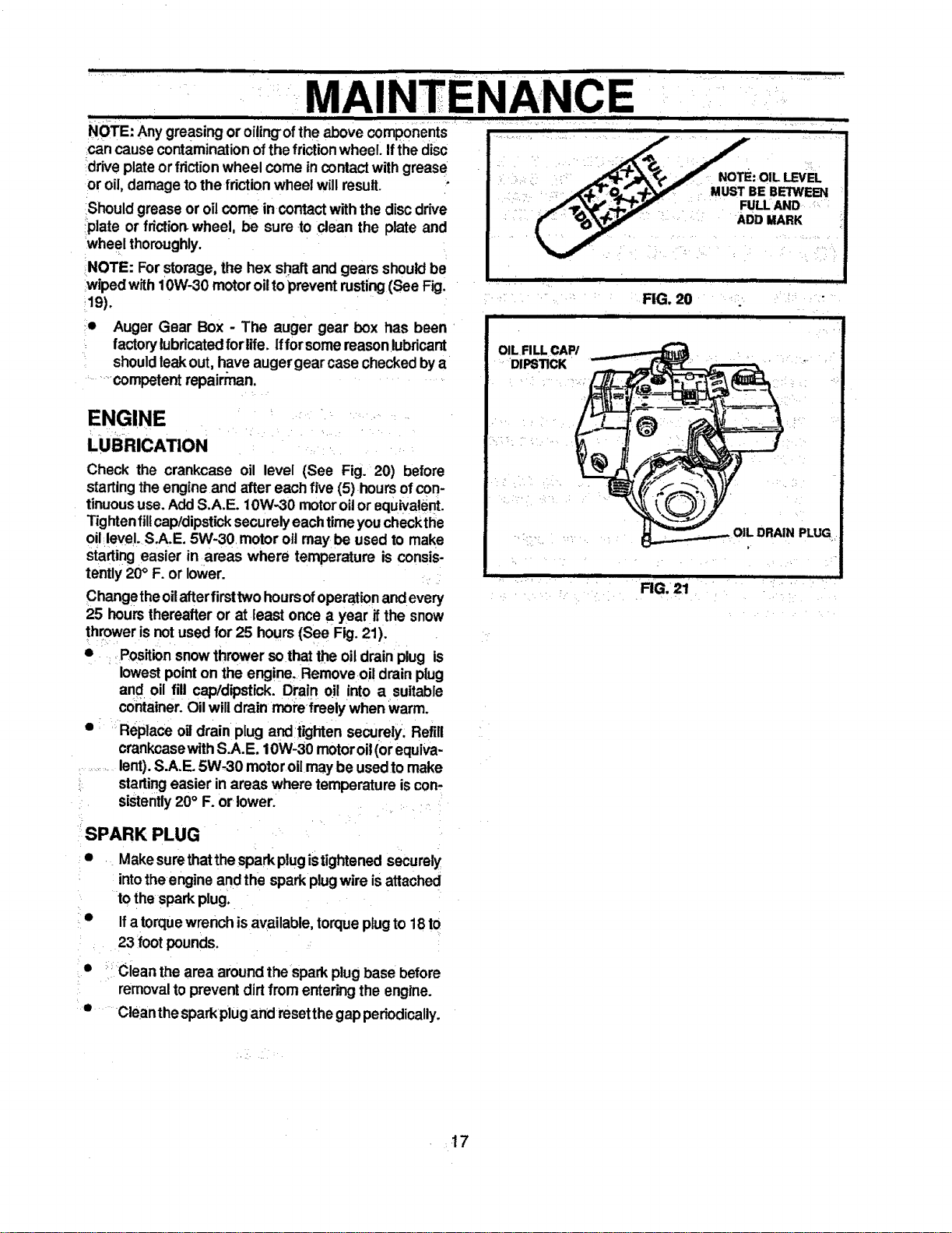
Check the crankcase oil level (See Fig. 20) before
startingthe engine and after eachfive (5) hoursof con-
tinuoususe. AddS.A.E. 10W-30 motoroilor equivalent.
"Fightenfil!cap/dipsticksecurelyeachtimeyou checkthe
oil level.S.A.E. 5W-30. motoroil may be used to make
stading easier in areas where temperature is consis-
tently 20° F. or lower.
Changetheoilafterfirsttwohoursofoperationandevery
25 hours thereafteror at least once a year ifthe snow
thrower isnot used for 25 hours (See Fig. 21).
• Positionsnowthrower sothat the oildrain plug is
lowestpointon the engine. Remove oil drain plug
and oil fill capldipstick. Drain 0il into a suitable
container.Oilwill drain morefreely when warm.
• Replaceoil drain plug andtighten securely. Refill
crankcasewithS.A.E. 10W-30 motoroil(orequiva-
.......lent).S.A.E. 5W-30 motoroilmay beusedto make
startingeasier inareas where temperature iscon-
sistently20° F. or lower. • •
SPARK PLUG
• Makesurethat thespark plugistightened securely
intothe engineand the sparkplugwire isattached
to the sparkplug.
• Ifa torquewrench isavailable,torqueplugto 18 to
23 footpounds.
_ Clean the area aroundthe spark plugbase before
removaltoprevent dirtfromenteringthe engine.
• Cleanthe sparkpiugand resetthegap periodically.
FIG. 20
OIL FILL CAP/
DIPSTICK
i
FIG.21
DRAIN PLUG
17
....SERVICE AND ADJUSTMEN
CAUTION: ALWAYS DISCONNECT THE
SPARK PLUG WIRE AND TIE BACK
AWAY FROM THE PLUG BEFORE MAK-
ING ANY ADJUSTMENTS OR REPNRS.
TO ADJUST SKID HEIGHT
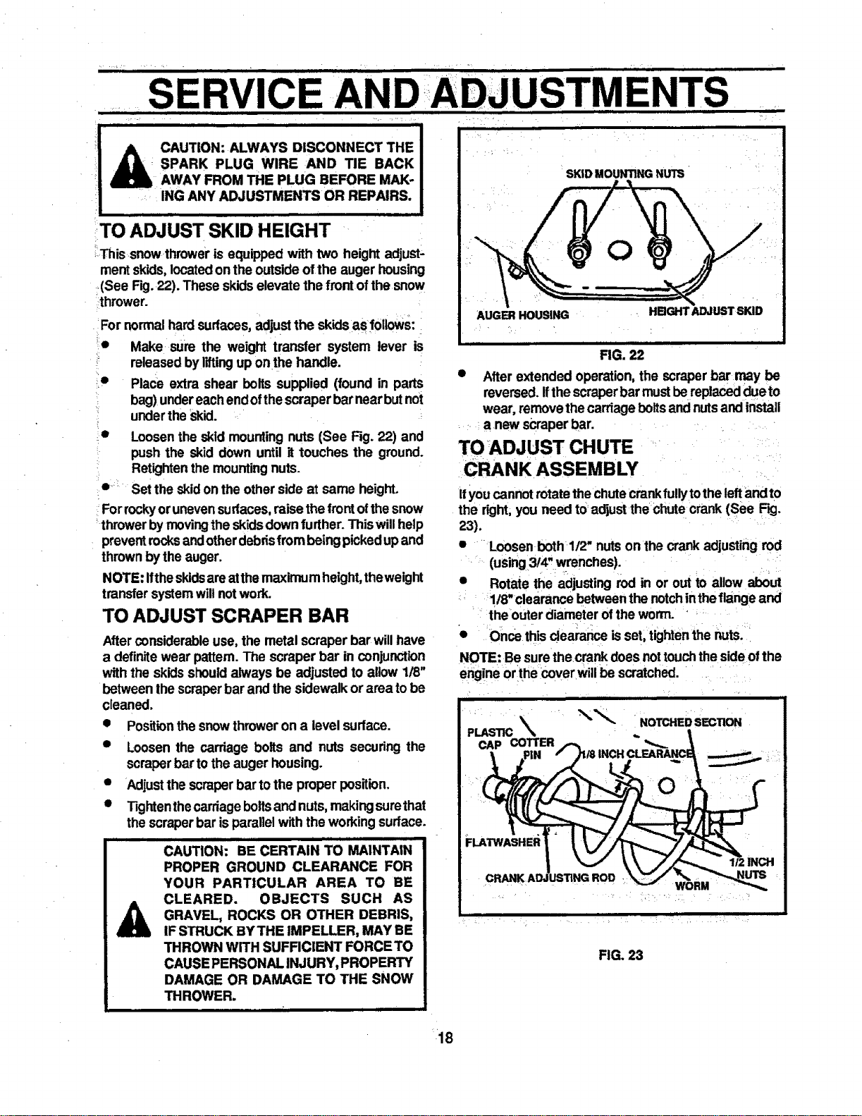
_Thissnow thrower is equipped with two height adjust-
ment skids,locatedon theoutside ofthe auger housing
(See Fig.22). These skids elevatethe frontof the snow
thrower.
For normalhardsudaces,adjustthe skidsas follows:
_e Make sure the weight transfer system lever is
i released byliftingup on the handle.
Place extra shear bolts supplied (found in parts
bag) undereachendofthescraper bar nearbutnot
• underthe skid.
• Loosenthe skid mountingnuts (See Fig. 22) and
pushthe skid down until it touches the ground.
_ Retightenthe mountingnuts.
i e: Set the skid onthe other side at same height.
Forrockyor unevensurfaces,raisethe frontofthesnow
-thrower by movingtheskidsdownfurther.Thiswillhelp
preventrocksand otherdebrisfrombeingpickedupand
thrownbythe auger.
NOTE: Ifthe skidsare atthemaximum height,theweight
transfersystemwillnotwork.
TO ADJUST SCRAPER BAR
After considerableuse, the metal scraper bar will have
a definite wear pattern. The scraper bar in conjunction
with the skids shouldalways be adjusted to allow 1/8"
between the scraperbar and the sidewalkor area tobe
cleaned.
• Positionthe snowthroweron a level sudace.
Loosen the carriage bolts and nuts secudng the
scraperbar tothe auger housing.
Adjustthe scraperbar tothe properposition.
Tightenthecarriageboltsand nuts,makingsurethat
thescraperbar isparallelwiththe workingsurface.
i i .H. i II Ill
CAUTION: BE CERTAIN TO MAINTAIN
PROPER GROUND CLEARANCE FOR
YOUR PARTICULAR AREA TO BE
CLEARED. OBJECTS SUCH AS
GRAVEL, ROCKS OR OTHER DEBRIS,
IF STRUCK BY THE IMPELLER, MAY BE
THROWN WiTH SUFFICIENT FORCE TO
CAUSE PERSONAL INJURY, PROPERTY
DAMAGE OR DAMAGE TO THE SNOW
THROWER.
i |11 i L
SKID MOUNTING NUTS
AUGER HOUSING
HBGHT ADJUST SKID
FIG. 22
• After extended operation,the scraperbar may be
reversed. Ifthe scraperbar must bereplaceddueto
wear, remove thecarriagebelts and nutsand install
a new scraperbar.
TO ADJUST CHUTE
CRANK ASSEMBLY
ifyoucannotrotatethechutecrankfullytotheleftandto
the right,you need tO adjustthechute crank (See Fig.
23).
• Loosen both 1/2" nuts onthe crankadjusting rod
(using3'4" wrenches).
• Rotate the adjusting rod in or out to allow about
1/8"clearancebetweenthe notchintheflangeand
the outerdiameter ofthe worm.
• Once thisclearar_e isset, tightenthe nuts.
NOTE: Be surethe crankdoes nottouchtheside ofthe
engine orthe cover willbe scratched.
PLASTIC
CAP COTTER
i ii
"_'_- NOTCHED SECTION
INCH
:LATWASHER
ira,iNCH
FIG. 23
_18
i ill i ]
TO ADJUST THE CLUTCH CONTROL
CABLES
Periodicadjustmentofthecables maybe requireddueto
normalstretchandwearon thebelts.To checkforcorrect
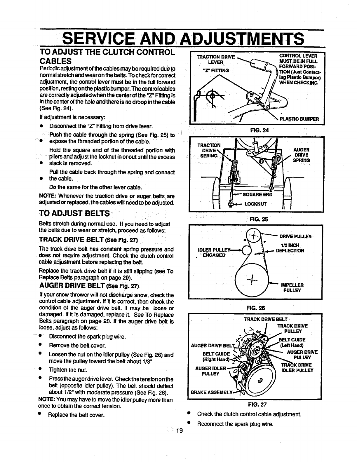
adjustment, the controllever must be in the lull forward
position,restingonthe plasticbumper.Thecontrolcables
are correctly adjusted when the centerofthe"Z"Fittingis
in thecenteroftheholeandthere isnodroopinthe cable
(See Fig. 24).
ff adjustment isnecessary:
e _Disconnec_the _Z"Fittingfrom drive lever.
_ _Push the cable throughthe spring(See Fig. 25) to
• expose the threaded portionofthe cable.
Hold the square end of the threaded portion with
......pliersand adjust theIocknutinorout untilthe excess
• slackis removed.
0
i ii . = m
SE AND ADJUSTM
i |
ii i
TRACTION DRIVE
LEVER
,Z" FffTING
Pullthe cable back throughthe springand connect
the cable.
Do the same for the other lever cable.
NOTE: Whenever the traction driveor auger beltsare
adjustedorreplaced,thecableswillneedtobe adjusted.
"•0
TO ADJUST BELTS
Belts stretch duringnormal use. If you need to adjust
the beltsdue to wear or stretch, proceed as follows:
TRACK DRIVE BELT (SeeFig. 27)
The track drive belt has constant spring pressure and
does not requireadjustment. Check the clutchcontrol
cable adjustmentbefore replacingthe belt.
Replace the track drive belt if it isstillslipping(see To
Replace Beltsparagraph on page 20).
AUGER DRIVE BELT (SeeFig. 27)
ifyour snowthrower willnot dischargesnow, checkthe
controlcable adjustment.If it is correct,then check the
condition of the auger drive belt. It may be loose or
damaged, if itisdamaged, replace it. See To Replace
Belts paragraph on page 20. if the auger drive belt is
loose,adjustas follows:
Disconnectthe sparkplug wire.
Remove the belt cover.
Loosenthe nut onthe idlerpulley(See Fig.26) and
movethe pulley towardthe belt about 1/8".
Tightenthe nut.
Presstheaugerddve lever.Checkthetension onthe
belt (oppositeidler pulley).The belt shoulddeflect
about 1/2"with moderatepressure (See Fig. 26).
NOTE: You mayhave tomovethe idlerpulleymorethan
once toobtainthe correct tension.
19
• Replacethe belt cover.
i i IL
i i,,
CONTROL LEVER
MUSTBE IN FULL
FORWARD POSI-
TION (Just Contact.
lng Plastic Bumper)
WHEN CHECKING
PLASTIC BUMPER
AUGER
DRIVE
f SPRING
FIG. 25
= H
Q_ DRIVE PULLEY
I), 1/2 INCH
IDLER PULLEY-.-._ ) .__,_L.,qw,-DEFLECTION
• ENGAGED _
' F IMPELLER
_ PULL_
AUGER DRIVE
PULLEY
FIG. 26
=l= i i =l i
TRACK DRIVE BELT
TRACK DRIVE
PULLEY
BELT GUIDE
AUGER DRWE
PULLEY
TRACK DRIVE
IDLER PULLEY
lit
FIG. 27
Check the clutchcontrolcable adjustment.
Reconnectthe spark plug wire.
AND ADJUSTMEN I'S
ii m ii . L
TO REPLACE BELTS
The drive beltson thissnowthrower are ol specialcon-
structionandshouldbe replacedwithoriginalequipment
beltsavailablefrom yournearest SEARS Store orServ-
iceCenter.
You willneed the assistanceof a secondperson while
replacingthe belts.
Drainthegasolinefrom thefueltankbyremovingthefuel
line. Drainthe gas and reinstallfuel line.
r, • •
AUGER DRIVE BELT
If your snow throwerwill not discharge snow, andthe
auger drivebelt isdamaged, replace itas follows:
• Disconnectthespark plugwire.
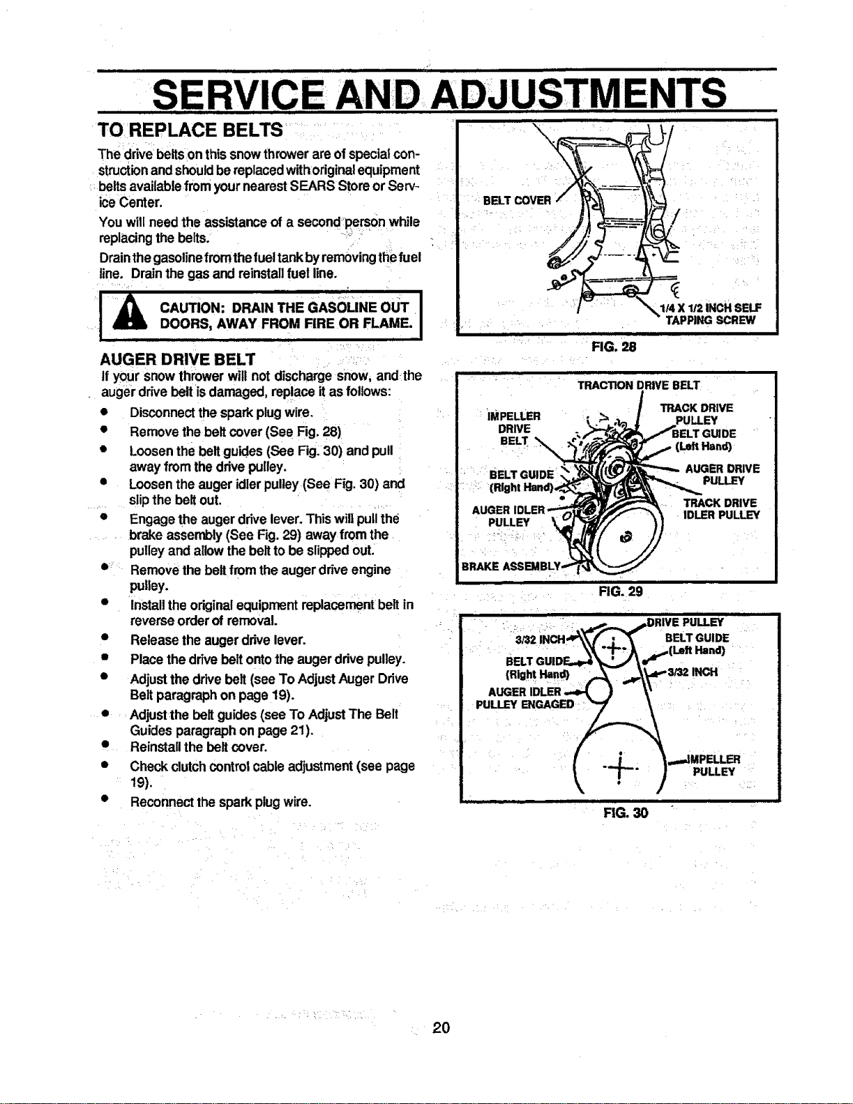
• Remove the belt cover (See Fig. 28)
• Loosenthe belt guides (See Fig.30) and pull
away from thedrive pulley.
• Loosen the auger idlerpulley(See Fig. 30) and
slipthe beltout.
• Engagethe augerdrivelever. Thiswillpullthe
brake assembly (See Fig. 29) away fromthe
pulleyand allow thebeltto be slippedouL
• Removethe belt fromthe auger drive engine
pulley.
• Installthe originalequipmentreplacementbelt in
reverseorder of removal.
e Release the auger drivelever.
• Place the drivebelt ontothe augerdrive pulley.
• Adjustthe drive belt (see To AdjustAuger Drive
Belt paragraphon page 19).
• Adjustthe belt guides (see To AdjustThe Belt
Guides paragraphon page 21).
• Reinstallthe belt cover.
• Check clutchcontrol cable adjustment(see page
19).
• Reconnectthe sparkplug wire.
BELTCOVER
, =, , J J
" FIG. 28
IMPELLER
DRIVE
BELT _
PULLEY
114X 112INCH SELF
TAPPINGSCREW
TRACTION DRIVE BELT
TRACK DRIVE
PULLEY
GUIDE
(Le_tHend)
AUGER DRIVE
PULLEY
TRACK DRIVE
IDLER PULLEY
BELT
PULLEY ENGAGED
i =f ii
FIG. 29
I
FIG. 30
..,.JMPELLER
PULLEY
L 20
• • i i [ •
..........SERVICE AN
III i I
TRACK DRIVE BELT "
• ,
ifyoursnowthrower willnc)tmoveforward,checkthe
trackdrivebelt for wean If the trackdrive belt needs to.
be replaced, proceed as fo!!ows:
• Disconnectthe spark plugwire.
• Remove the belt cover.+,
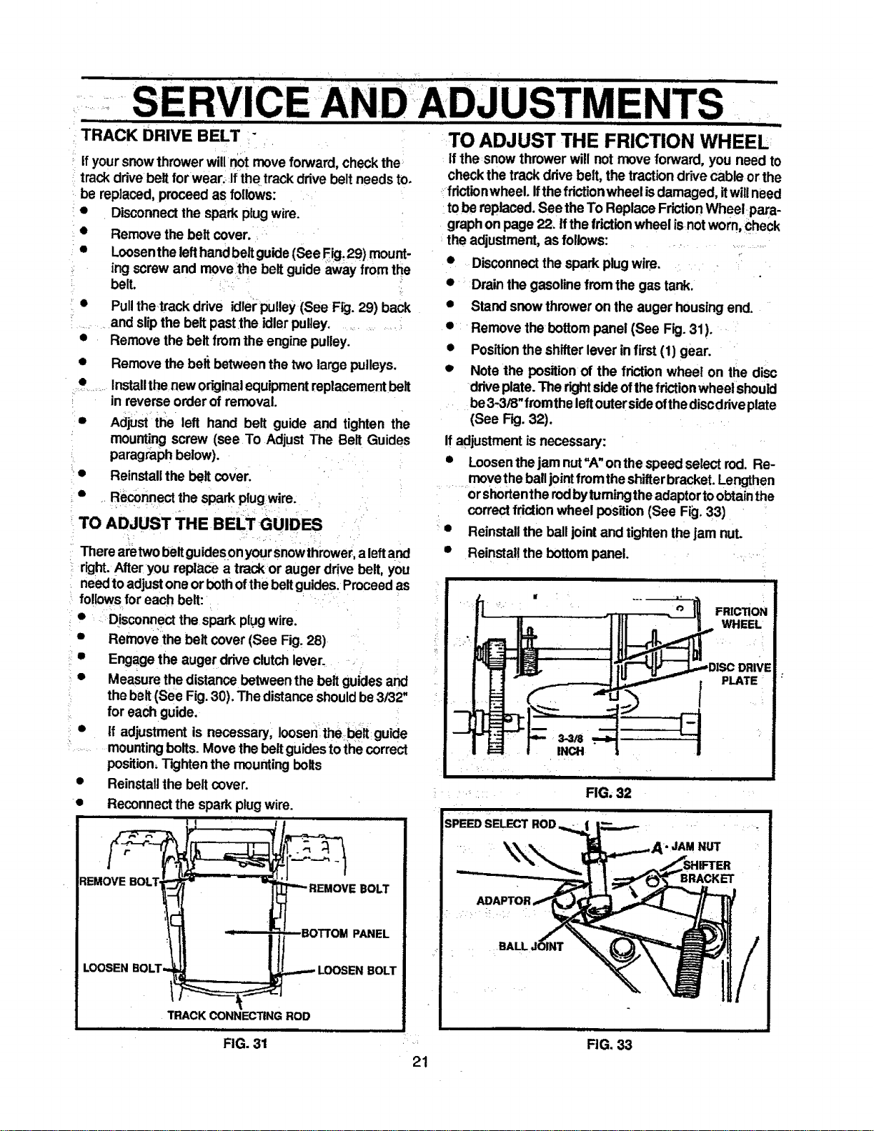
• Loosenthe lefthandbeltguide(See F_, 29) mount-
ing screwand movethe belt guide away fromthe
belt. +!+," .,
• Pullthetrackdriveidlerpulley(SeeFig.29)back
and slipthe belt past.the idlerpulley........
• Remove the belt from the engine pulley.
• Remove the beli between the two large pulleys.
• Installthe neworiginalequipmentreplacementbelt
in reverse order of removal.
D
e
o
Adjust the left hand belt guide and tighten the
mountingscrew (see To Adjust The Belt Guides
paragraphbelow).
Reinstallthe belt coven
Reconnectthe spark plugwire.
. + :
TO ADJUST THE BELT GUIDES
Therearetwobeltguides0n yoursnowthrower,a leftand
right.Afteryou replace a trackor auger drive belt, you
needto adjustone or bothofthebeltguides. Proceedas
follows foreach belt:
• Disconnectthe spark plugwire.
• Remove the belt cover (See Fig. 28)
• Engage the auger drive clutchlever.
• Measure thedistance between the belt guides and
thebelt (See Fig.30). The distanceshouldbe3/32"
for eachguide.
• if adjustment is necessary, loosen the.belt guide
mountingbolts. Move thebeltguidesto thecorrect
position,Tightenthe mounting bolts
• Reinstallthe beltcover.
• Reconnectthe spark plug wire.
iiiii l i i
I ! I
REMOVE BOLT
iiiiiiii+
LOOSEN BOLT.
TRACK CONNECTING ROD
ii i
FIG. 31
21
.......................USTMENTS
IIIIIIII I I II IIII IIIII I I I ill I I I II i
TO ADJUST THE FRICTION WHEEL
if the snow thrower will not move forward, you need to
checkthe trackdrive belt,the tractiondrivecable or the
.:fdctionwheel. Ifthe frictionwheel isdamaged, itwillneed
tobe replaced.See the To ReplaceFrictionWheetpara-
graph on page 22. Ifthefrictionwheel isnot worn,_heck
the adjustment,as follows: .......................
• Disconnectthe spark plugwire.
• Drain the gasolinefrom the gas tank.
• Stand snow thrower on the auger housingend.
• Remove the bottompanel (See Fig.31). +:
• Positionthe shifterlever in first (1) gear.
• Note the position of the frictionwheel on the disc
driveplate. The rightsideofthefriction wheelshould
be3-3/8"fromthe leftoutersideofthediscdriveplate
(See Fig.32). •
Ifadjustmentis necessary:
• Loosenthejam nut"A"onthe speed selectrod. Re-
.........move theballjointfromtheshifterbracket.Lengthen
orshortentherodbyfumingtheadaptortoobtainthe
correctfrictionwheel position(See Fig. 33)
• Reinstallthe balljointand tighten thejam nut.
• Reinstallthe bottompanel. . .
I
........... FIG. 32
iiiiii ii i
SPEED SELECT ROD
i i i
•JAM NUT
BRACKET
P
U I_L I
FIG. 33
SERVICE AND AD
i
TO REPLACE FRICTION WHEEL
Ifthesnowthrowerwillnot moveforward,andthefdcUon
wheel isworn or damaged, you need to replace it, as
follows:(First allow the engine to cool).
_EMOVE
LOOSENBOLT,
n n i i
• Drainthe gasolinefrom the fuel tank by removing
thefuelline. Drainthefueland reinstailthefuel line.
• Disconnectthe spark plugwire.
• Stand the snow thrower up on the auger housing
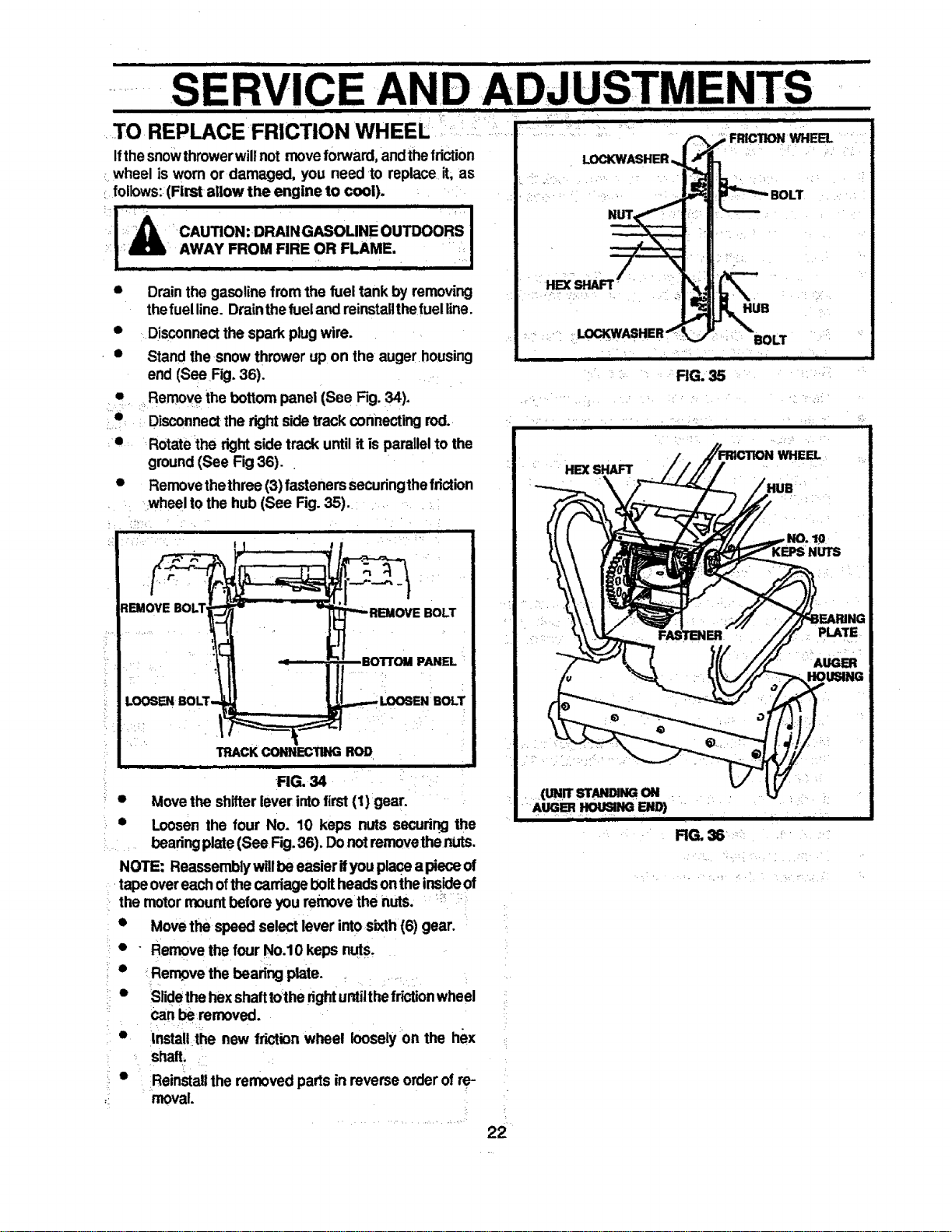
end (See Fig.36).
• =_Removethe bottom panel (See Fig. 34).
• : Disconnectthe right sidetrack connectingrod.
• Rotatethe rightside track until it is parallelto the
ground(See Fig 36).
• Removethethree (3)fasteners securingthefriction
=wheelto the hub (See Fig. 35).
BOTTOM PANEL
TRACKCONHEC'flNGROD
FIG. 34 •
Movethe shifterlever intofirst (1)gear.
Loosen the four No. 10 keps nuts securirngthe
. beadngplate (See Fig.36). DonotrernovethenUts.
NOTE: Reassemblywillbe easier ifyouplace a pieceof
tapeovereachofthe carriage10oifheads ontheinsideof
the motormount beforeyou remove the nuts. _;_:
• Movethe speed selectlever intosixth (6) gear.
• " Removethe four No.10 keps nuts,
* Rerr_ve the beadng plate.
• Slidethe hexshafttothe rightuntilthefrictionwheel
ca" removed.
• !nstallthe new frictionwheel looselyon the hex
shall ,
• Reinstallthe removedparts in reverse order of re-
moval
LOCKWASHER'
FIG. 35
m l
HEXSHAFT
FRICTION WHEEL
HUB
BOLT
i i
WHEEL
ING
PLATE
AUGER
ii i i iiii ii ii Hill II1-1
................... 22
j i ii • tl i ii iii i i
S AN
i t t, , i t
I I I III I II
TO REPLACE AUGER SHEAR BOLT
r
The augers are securedto the auger shaftwith special
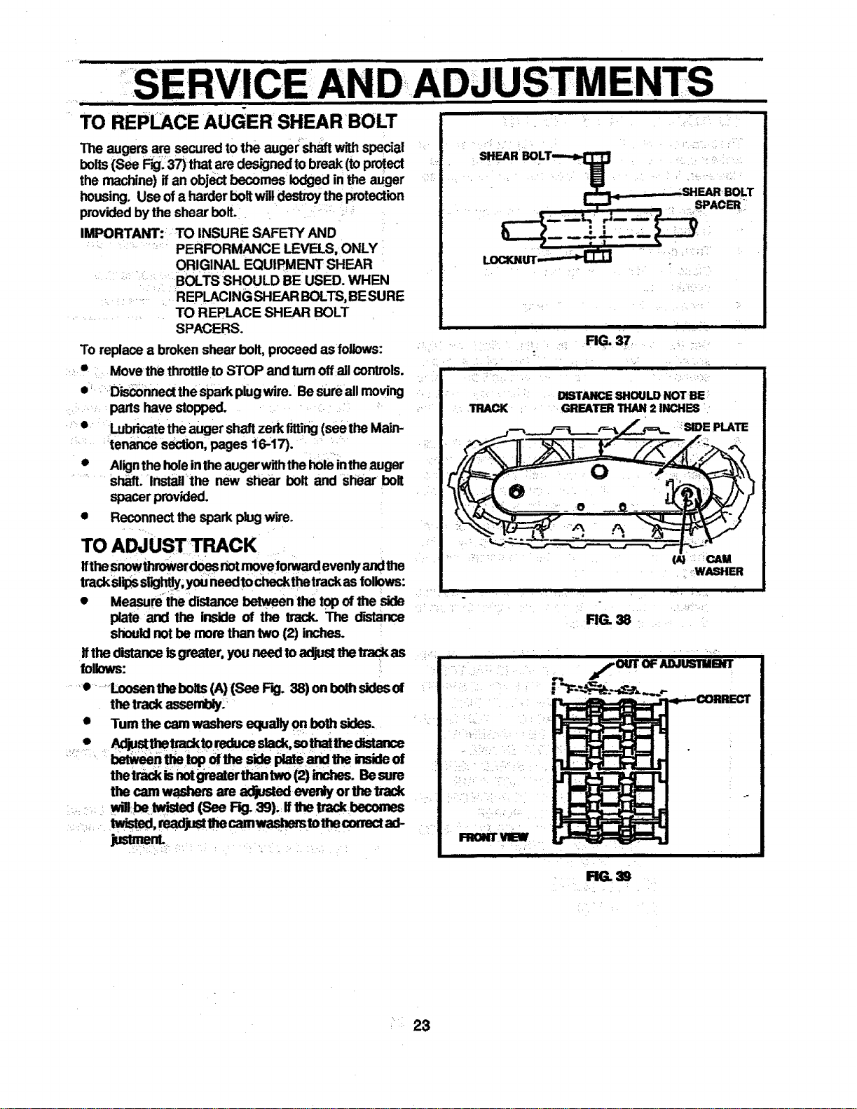
bolts(See F_.37)that aredesignedto break (toprotect
the machine) ifan object becomes lodgedin _ auger
housing. Use ofa harder boltwilldestroythe protection
providedbythe shear bolt.
IMPORTANT: TO INSURE SAFETY AND
PERFORMANCE LEVELS, ONLY
ORIGINAL EQUIPMENT SHEAR
BOLTS SHOULD BE USED. WHEN
REPLACING SHEAR BOLTS,BESURE
TO REPLACE SHEAR BOLT
SPACERS.
To replace a broken shear bolt, proceed as follows:
• =Move the throttleto STOP and rumoff all controls.
• D'_nnect the sparkplugwire. Besureall moving
parts have stopped.
• Lubricatetheauger shaftzerk fitting(see the Main-
tenance section, pages 16-17).
• Alignthe holeinthe augerwiththe holeintheauger
shaft. Installthe new shear bolt and shear bolt
spacer provided.
• Reconnectthe spark plugwire.
TO ADJUST TRACK
ifthesnowthrowerdoes notmoveforwardevenlyandthe
trackslipss6gh_y_,youneedto checkthetrackas foliows:
• Measumthe dislance between the top ofthe side
plate and the inside of the track. The d'Blance
shouldnot be mornthan two (2) inches.
tithe distanceIsgreater, you need toadjustthetrackas
follows: _.
•• ......Lcosenthebolts(A)(See F_I. 38)onbomsidesof
thetrackassernU_-
• Turn the cam washers equally on both sides.
* _justthetracktoreduces_c_.somam_e¢mnce
thetrackisnotgreaterthan two(2) inches. Besure
the cam washers are adjusted evenly or the track
=: ,,.. wmbe :_ (See RO. 3S).:Uthe Uackbecomes
_nL .............
SHEARBOLT--_
"
: l
_UT .
i i
TRACK
E, -,:•
RG. 37.
k
DISTANCE SHOULD NOT BE
GREATBFi THAN 2 INCHES
SIDE PLATE
O
i
(A) _:_CAM
_WASHER
RG. 38
LJ'T'F.,q-'T-q'-I_
tt,,tttttt,,, i II I
:;i
TO ADJUST CARBURETOR ....
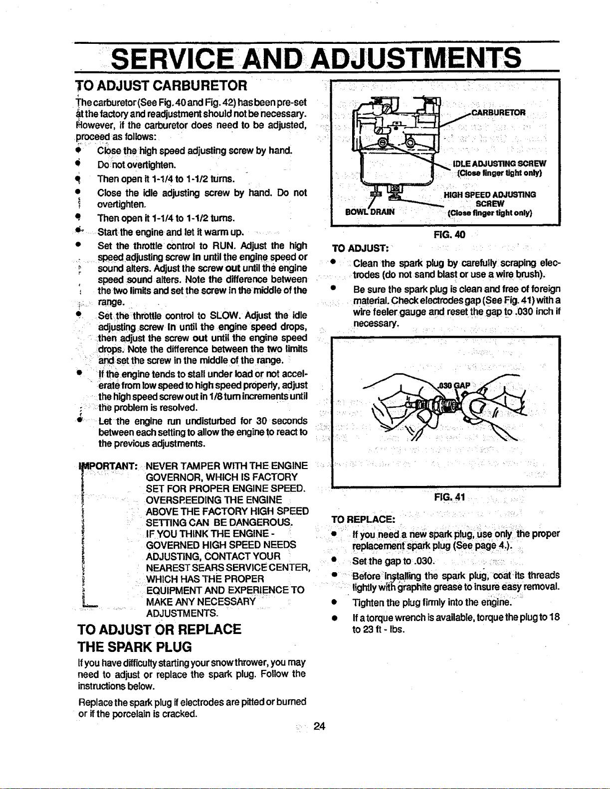
The carburetor(See Fig.40 and Rg. 42) hasbeen pre-set
_t thefactoryandreadjustmentshouldnotbe necessary.
_lowever, if the carburetor does need to be adjusted,
proceed as follows:
• Closethehigh speed adjustingscrewby hand.
• Do notovertighten. ._
q, Then openit 1-114to 1-1t2 turns.
• Close the idle adjusting screw by hand. Do not
! overtighten.
q Then open it1-1!4 to 1-1/2 turns.
_' .Start:theengineandletitwarmup. •
• Set the throttle=controlto RUN. Adjust the high
speed=adjustingscrewin untilthe engine speed or
_i ' sound alters.Adjustthe screw out untilthe engine
speed sound alters. Note the difference between
•_ thetwo limitsand setthe screw inthe middleof the
_::. range.
e .Setthe_thmttle control to SLOW. Adjust the idle
adjusting .screw in untilthe .engine speed drops,
. , :.then adjust the screwout until the engine speed
:drops, Note the difference between the two limits
_-! andset the screwinthe middleof the range,
L • '
e- If the,enginetendsto stall under loador notaccel-
" erate from lowspeedtohighspeed properly,adjust
thehighspeedscrewoutin118turnincrementsuntil
:. :the problemisresolved.
€
Let-the engine run undisturbed for 30 seconds
between eachsettingtoallowthe engineto reactto
the previousadjustments.
I DIPORTANT: NEVER TAMPER WITH THE ENGINE
' :: " GOVERNOR, WHICH IS FACTORY
SET FOR PROPER ENGINE SPEED.
OVERSP.EEDING THE ENGINE
?
L ABOVE THE FACTORY HIGH SPEED
"_ .L SETTING CAN BEDANGEROUS.
IF=YOU THINK THE ENGINE - "
GOVERNED HIGH SPEED NEEDS
ADJUSTING, CONTACT YOUR
NEAREST SEARS SERVICE CENTER,
L WHICH HAS THE PROPER
....EQUIPMENT AND EXPERIENCE TO
L .. MAKE ANY NECESSARY
ADJUSTMENTS.
TO ADJUST OR REPLACE
THE SPARK PLUG
Ifyouhavedifficultystartingyoursnowthrower,you may
need to adjust or replace the spark plug. Follow the
instructionsbelow.
Replace thespark plugifelectrodesare pittedor burned
or itthe porcelainiscracked,
RG. 40
TO ADJUST: .......
• Clean :the spark plug bycarefully scraping elec-
..... trodes (do not sand blastor use awi m brush).
• Be sure the sparkplug isclean and free offoreign
material.Check electrodesgap (See Fig.41) witha
wire feeler gauge and resetthegap tO .030 inchif
necessary.
,11,,,, ii
FIG. 41
i
TO REPLACE:
If youneed a newspark p!ug,Useonlythe proper
replacementspark plug (See page 4.), .
• Set the gap to .030. :-:::_
• ' Beforein_taliing the spark plus, coat.its threads
lightlyw_h graphitegreaseto insureeasy removal.
o =.
• Tightenthe plugfirmly intothe engine.
• Ifatorque wrenchisavailable,torquetheplugto18
to23 ft - Ibs.
[ii , i,,,,,ii ,,,,, ii i i Hll l m I Ill I Iill I : _; IIIIIIIIIIIIIILI
iiiiii i iji
CAUTION: NEVER STORE YOUR SNOW
THROWER INDOORS OR IN AN EN-
CLOSED, POORLY VENTILATED AREA
IF GASOLINE REMAINS IN THE TANK. FUMES
MAY REACH AN OPEN FLAME, SPARK OR PI-
LOT LIGHT FROM AFURNACE, WATER HEATER,
CLOTHES DRYER, ClGARETi'E, Ei'C.
To preventengine damage (if snowthroweris notused
for more than 30 days) followthe stepsbelow.
ENGINE STORAGE
Gasollnemust be removed or treated to prevent gum
deposits from forming in the tank, filter, hose, and
carburetor during storage. Also during storage, al-
cohol blended gasoline that uses ethanol or metha-
nol (sometimes called gasohol) attracts water. Itacts
on the gasoline to form acids which damage the
engine.
• To remove gasoline,runthe engineuntilthetank is
emptyand the engine stops.Then drainremaining
gasoline from carburetor by pressing upward on
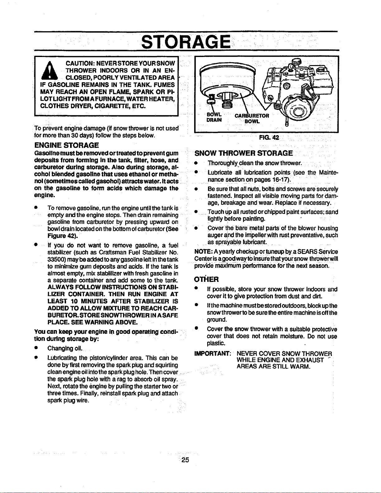
bowldrain locatedon thebottomofcarburetor(See
Figure 42).
• If you do not want to remove gasoline, a fuel
stabilizer (such as Craftsman Fuel Stabilizer No.
33500) maybeaddedtoanygasolineleft inthetank
to minimizegum depositsand ackls. Ifthe tank is
almost empty, mix stablilizer withfresh gasolinein
a separate container and add some to the tank.
ALWAYS FOLLOW INSTRUCTIONS ON STABI-
LIZER CONTAINER. THEN RUN ENGINE AT
LEAST 10 MINUTES AFTER STABILIZER IS
ADDED TO ALLOW MIXTURE TO REACH CAR-
BURETOR, STORE SNOW'i'HROWER IN ASAFE
PLACE. SEE WARNING ABOVE,
You can keep your engine in good operaUng condi-
tion during storage by:
• Changingoil.
• Lubricatingthe piston/cylinder area. This can be
donebyfirstremovingthe sparkplugand squirting
cleanengineoilintothe sparkplughole.Thencover ....
the spark plug holewith a rag to absorb oil spray. •
Next, rotatethe engine by pullingthe startertwoor
three times. Finally,reinstallspark plugand attach
spark plugwire. =
DRAIN
BOWL
RG. 42
SNOW THROWER STORAGE
• Thoroughlyclean the snowthrower.
• Lubricate all lubrication points (see the Mainte-
nance sectionon pages 16-17).
• Be surethatall nuts,belts and screwsare securely
fastened. Inspectall visible moving parts fordam-
age, breakage and wear;Replace ifnecessary.
• Touch upallrustedor chippedpaintsurfaces;sand
lightly beforepainting.
• Cover the bare metal pads of the blower housing
augerand the impellerwith rust preventative, such
as sprayable lubricant.
NOTE: A yearlycheckuportuneupby a SEARS Service
Centerisagoodwaytoinsurethatyoursnow throwerwill
provide=_imum performancefor tha next season.
O'I_IER
• if possible, store your snow thrower indoors and
cover it togive protectionfrom dust and dirt.
• Ifthe machinemustbestoredoutdoors,blockupthe
snowthrowertobe suretheentiremachineisoffthe
ground.
• Coverthe snow thrower with a suitable protective
cover that does not retain moisture. Do not use
plastic.
IMPORTANT:
NEVER COVER SNOW THROWER
WHILE ENGINE AND EXHAUST "
AREAS ARE STILL WARM.
25
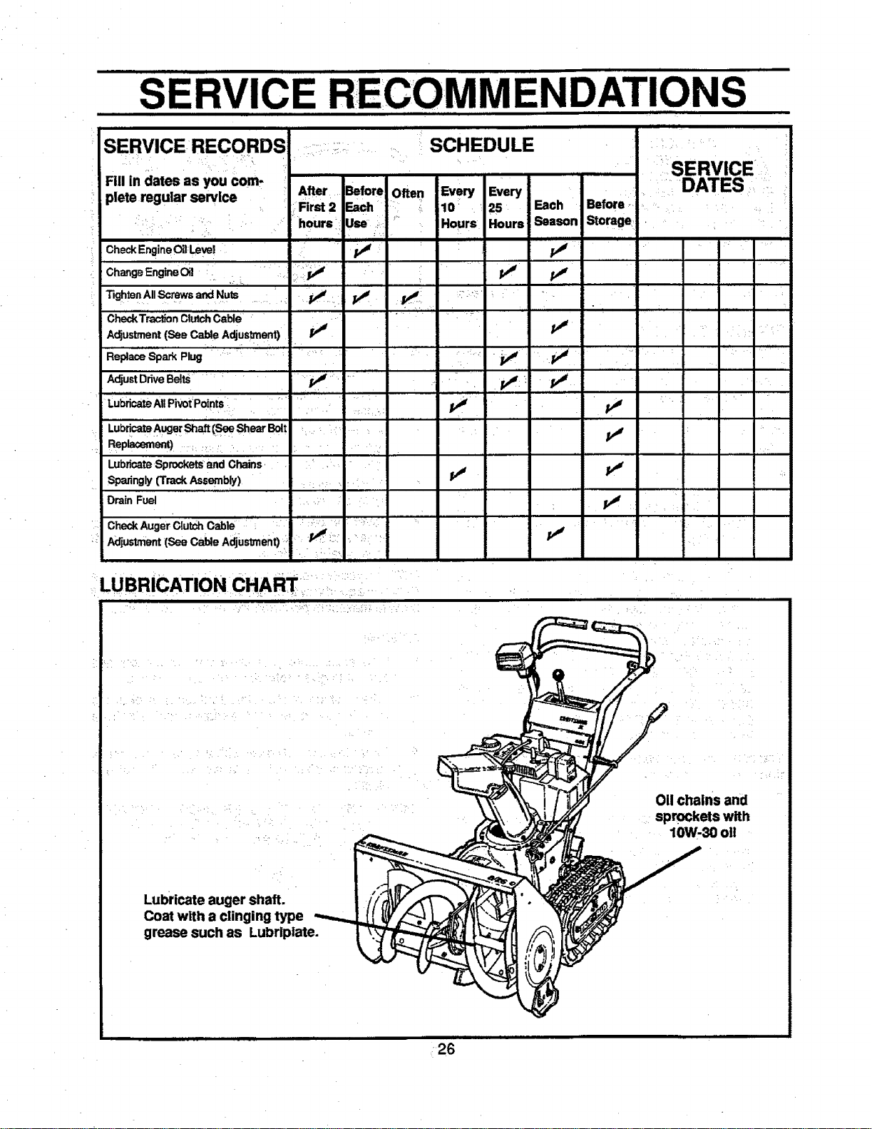
SERVICE RECOMMENDATIONS
,,,, ,i
SERVICE RECORDS .....:_ : SCHEDULE '
Fill in dates as you com.
_=:SERVICE
CheckEngne0_1Level
ChangeEngine Oil
Tighte a All Screws and Nuts ....... _.,
] i i
:r After Before Often Every Every
_':-First 2 Each " :i 10 : . 25 Each Before ...... _ , L
hoursl Use...... Hours Hours Season Storage ....
• ,. L "| , ., •
GheckTract_n ClutchGable
Adjustment (See Cable Adjustment)
A_u=Dr_veBeBts: " V" ' __ "'" " 11-
Replacement):., , . . . ,:
,i,
Lubricate Sprockets and Chains. • ' . . .
, v' ti _,
Drain Fuel ' , '
...... ' • 11 , =
Check Auger ClutchCable • : l .... • , ;....
Adjustment'(See Cable Adjustment) ,' '_:- :•: , ,:.... I
LUBRICATION CHART:
011chains and
sprockets with
10W-30 oll
Lubricate auger shaft.
Coat with a clinging type
grease such as Lubriplate.
26
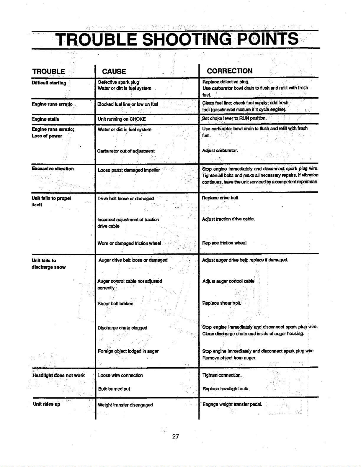
TROUBI, E SHOOTING POINTS
, iiii i i i i ii mill I
TROUBLE
Diffieuit starting
Engine runs erratic..
Engine stalls
CAUSE
I II IIII IIIII
Defectivespark0ug
Water or _rt in fuel system
ill i_ ii i
Blocked fuelSneer low on fuel
UnitrunningonCHOKE
Engine runs el'ratio;
Loss of power
,,,, • ,,i ,
Excessive vibration
Unit fails to propel
Itself
Unit falls to
discharge snow
Headlight does not work
Unit rides up
Water or dirt in fuel system
Cmbumtor outof adjustmont
Looseparts; damaged impeller
Ddve belt loose or damaged
inoormctadjustment ofIt-action
drivecable
Worn or damaged frk:tlonwheel
] Ir I I|lll
Auger drive belt loose or damaged
Auger controlcable notadjusted
corre_
Shear bolt broken
Discharge chute dogged
Foreignobjestlodgedinauger
Loosewire o_nnec_on
Bulbburned out
HHI I
Weight transfer disengaged
CORRECTION
iii
Replace defective plug.
Use carburetor bowldrain to flush and refillwith fresh
fuel.
H lIJ_ IJ I
Clean fuelline;check fuel supply;add flesh
fuet;(gaseline/oil mixture if 2 cycleengine) ....
UNpesi£;;
Set choke lever to
Use carburetor bow]drain to flush and refillwith fresh
fuel.
Adjustcerbumtor.
i
Stop eng!,ne immed'_ly and diso=nnect sparkplug wire.
Tighten all bolts and make ell necesse_ mpairs:ff vibration
con_nues,have the unitserviced byacompetent repairman
Replace c_ivebelt
AdjustIraction ddve cable.
Replace friction wheel.
HIe HI m rl
Adjustaugerdrivebe_;replaseifdamaged.
Adjust auger oontrol cable
Replace shear bolt..
Stop engine immediately and disconnect spark plug wire.
.... Clean dischatgechute and inside ofauger housing.
Stop engine immediately and disconnect spark ldug wire
Removeobject from auger.
Tighten connection.
Replace headlightbulb.
Engage weight transfer pedal.
• %
27
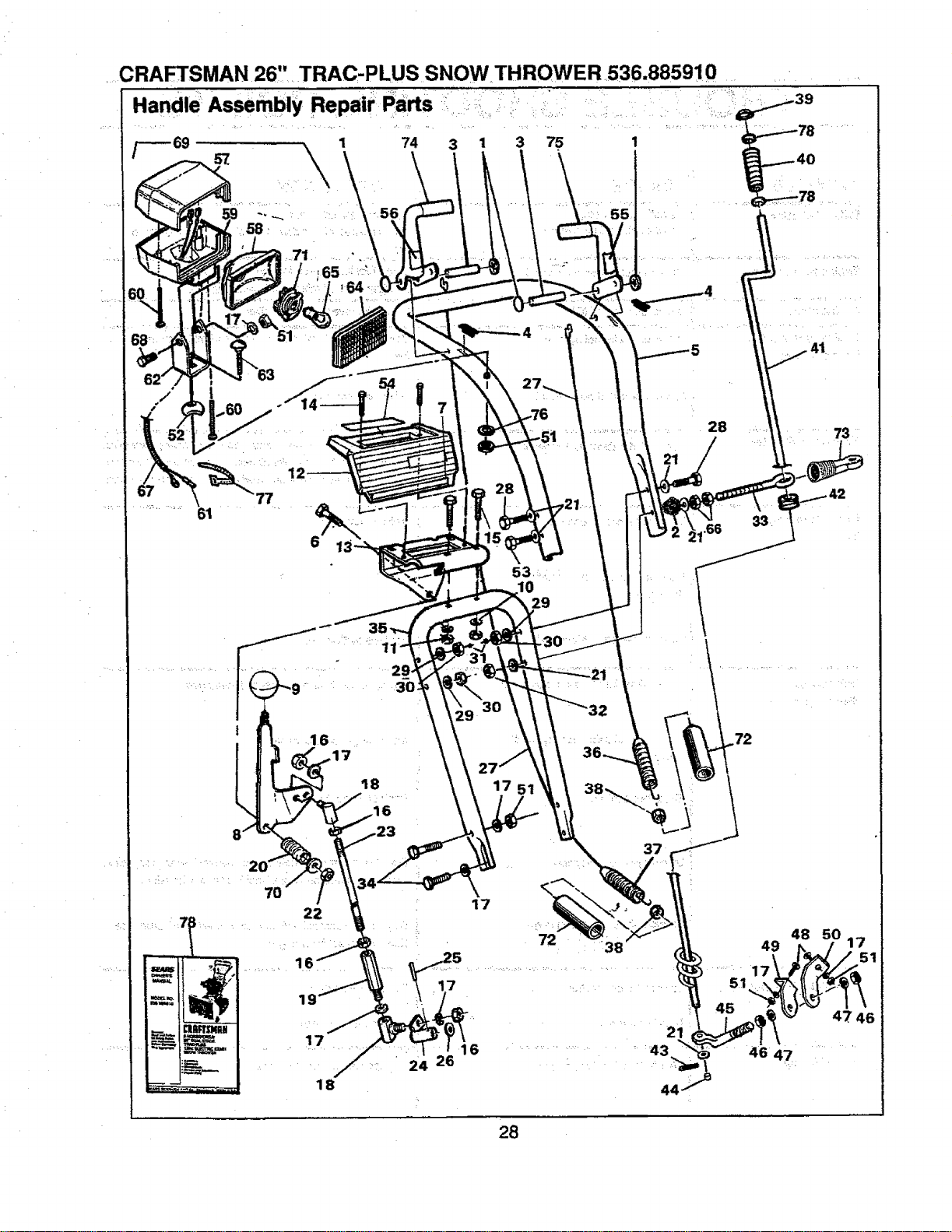
CRA_SMAN 26" TRAC-PLUS SNOW THROWER 536.885910
Assembly RepaW PartS i :_:::!, i :: : : :::: =_I_:,:_ 39
....71
: _= "1
61
77
7
.66
...... 731 ¸
k
" i¸ ': L • •
...., 16, _ :
,17
t8
22
_ _,_: _ 1,, ,
m
17
H _:_i_
18
37
17
72 : 38
17 _-
24 26
16 ............. 43
72
49
....... 17_
51
45
48 50
47 46
4647
28
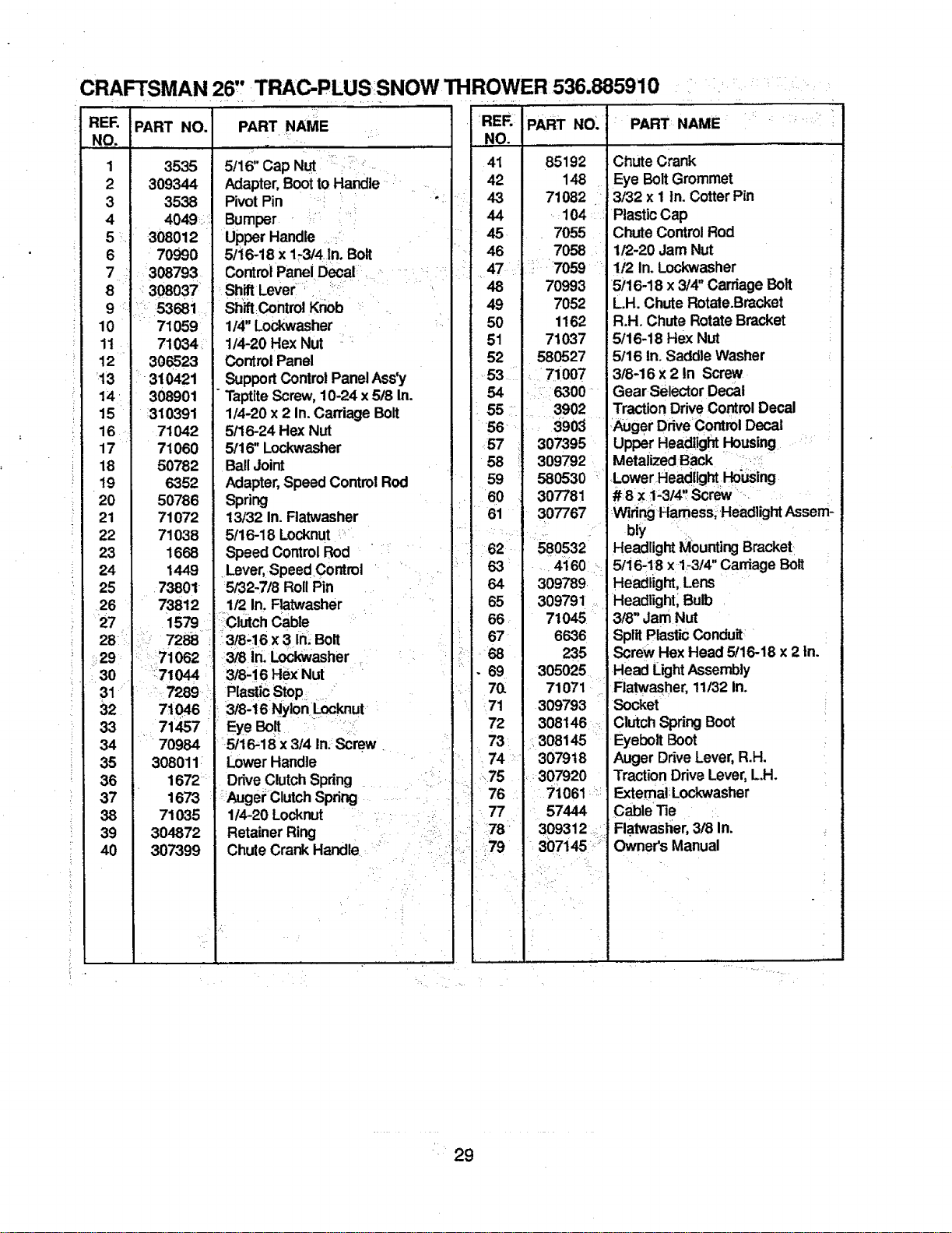
CRAFTSMAN 26', TRAC-PLUS SNOW THROWER 536.885910
RE[=. PART NO.
NO.
1 3535
2 309344
3 3538
4 4049 ::.
5 308012
6 70990
8
.
10
11
12
'13
14'
15
16
17
18
19
20
21
22
23
24
25
26
7 _308793
• 308037
53681
71059
71034.
306523
i- 310421
308901
310391
71042
71060
50782
6352
50786
71072
71038
1668
1449
73801
73812 .......!/21n. Ratwasher .
27 1579 :Clutch Cable
28: I 7288 i_3/8:,16x 3 In__Bolt
_29
30
31 _
32
33
34
35
36
37
38
39
40
PART NAME ,:i
5/16" Cap Nut : _.
Adapter,Bootto Haadle- •
Pivot Pin ".
Bumper ' ,/:
Upper Handle .:::i
5/i6-18 x 1-3/4 In.Bolt
ControlPanel Decal, .........
,Sh tLever::.................
ShiftContml K_b "
114"Lockwasher
1/4-20 Hex Nut ....
ControlPanel
SupportControlPanelAss'y
"Taptite Screw, 10-24 x 5t8 In.
1/4-20 x 2 In.Carriage Bolt
5/16-24 Hex Nut
5/16" LodoNasher
BallJoint
Adapter, Speed Control Rod
Spring
13/32 In. Flatwasher
5/16-18 Locknut :"'
Speed Control Rod • : .....
Lever,Speed Control ' •
5/32-7/8 Roll Pin
:ii:71062 ;: 3/8 irl.Lockwasher
:71044 : 3/8-16 Hex Nut
7289 Plastic Stop
71046 : 3!8-16 NylonLocknut_•
71'497 EyeBolt ::i:i
70984 5/16-18 x 3/4 In;Screw, .
308011 _ LowerHandle ....:
1672 _ DriveClutchSpring ........ ..:i:,.
1673 i _Augei_ClutchSpdng
71035 1/4-20 Locknut ...... :.:
304872 Retainer Ring .... .::;
307399 ChuteCrank Handle. :, ....... :_'
RER PART NO.
NO.
41 85192
42 148
43 71082
44 .:104::i
45 . 7055
46 7058
_":i:."7059
48 70993
49 7052
50 1162
51 71037
52 580527
53 :• 71007
54 •: 6300"
55 .... 3902
56 ' .....390_ .....
57 307395
58 309792
59 580530
60 307781
' 61 307767
I ?
162 580532
63 : .....4160".
64 309789.
65 309791.,
66. 710_
67 6636
:.68 235
.69 305025
70, I 71071
71 309793
72 308148
73: ... 308145 _
74: 307918
-"75 307920
76 71061 :'!
77 : 57444
" :78:" 309312: _
•79 307145 _":;
i
" PART: NAME _ : : :_: :
k
Chute Crank
Eye Bolt Grommet
3t32 x 1 In. Cotter Pin
Plastic Cap
Chute Control Rod
1/2-20 Jam Nut
1/2 In. Lockwasher
5/16-18 x 3/4" CarriageBolt
L.H. Chute Rotate.Bracket
R.H. Chute RotateBracket
5/16-18 Hex Nut
i 5/16 In. Saddle Washer
3/8-16 x 2 In Screw
Gear selector Decal
TractionDriveControlDecal
,:AugerDdveContml Decal :
Upper Headl!ghtHousing ';
Metaiized Back ..... ::!:
,.LowerHeadlight,Housing
#8x 1-3/4'_Screw '..
WidngHamess_Headlight Assem-
bly •_,
Headlight Mounting Bracket
5/i6,18 x 1-3/4"CarriageBolt
Headlight,Lens
Headlight; Bulb
3/8" Jam Nut
SplitPlasticConduit
ScrewHex Head 5/16-18 x 2 In.
Head LightAssembly
Flatwasher, 11/32 In.
Socket
ClutchSpringBoot
Eyebolt Boot
Auger DriveLever,R.H.
TractionDdve Lever,L.H.
Extemal:Lockwasher
Cable'lie
Flatwasl_er,3/8 In.
Owners Manual
• 29
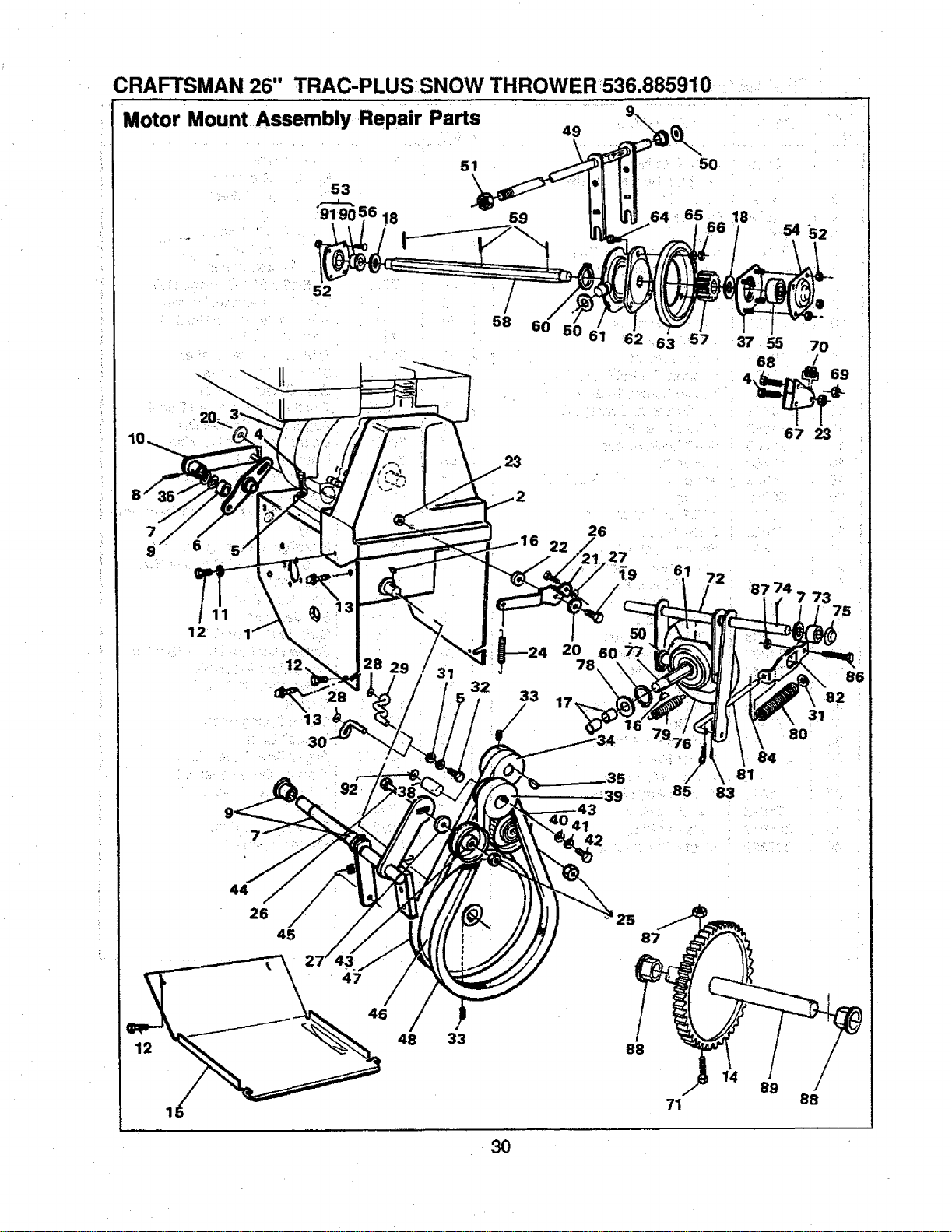
CRAFTSMAN 26" TRAC-PLUS SNOWTHROWER536.885910
Motor Mount Assembly ,Repair Parts
9
49
53
51
\
18
23
6O
57
3755 70
6e -"/ 6e
4
67 23
6
11
=. 13
30"
7
92
8 29 /31
33
5O
39
41
42
61
85
72
87 74
\ 84
81
83
7 73
31
80
15
44
26
/
45
47
46
48
33
25
88
87
71
14
89
88
3O
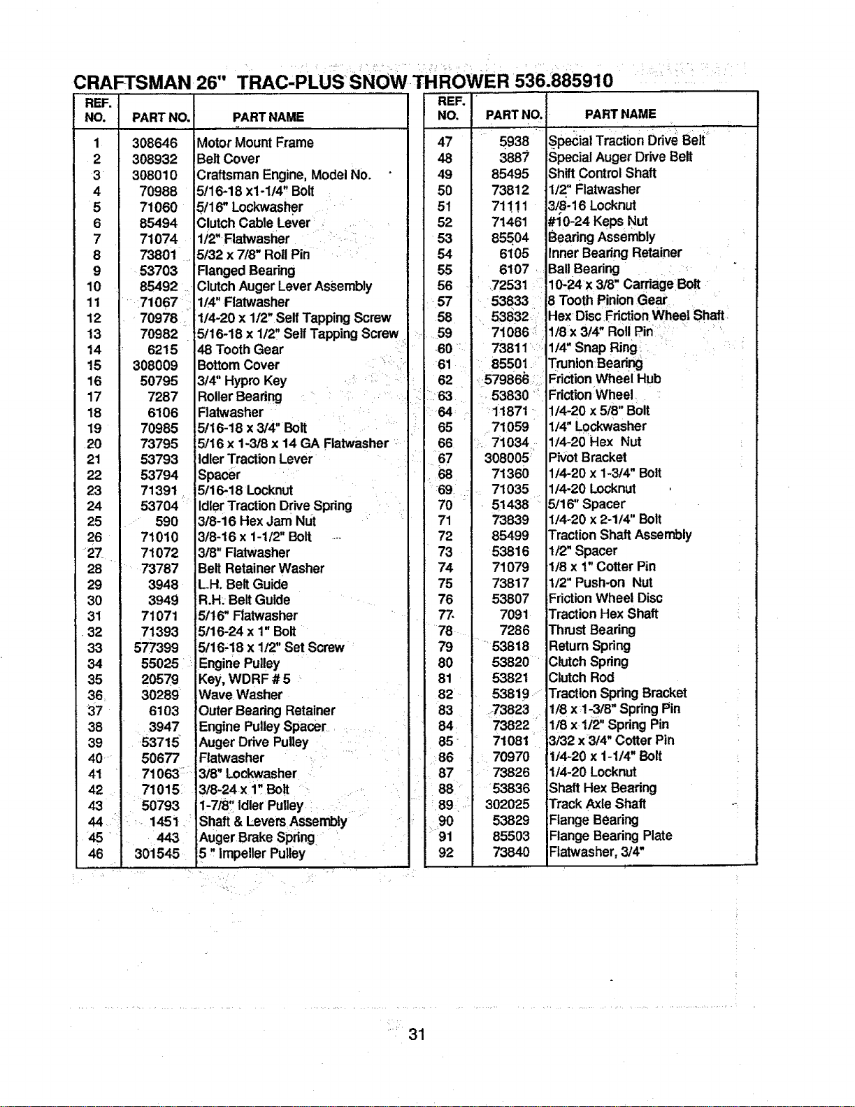
CRAFTSMAN 26"
REF.
NO. PARTNO.
1 308646
2 308932
3 308010
4 70988
5 71060
6 85494
7 71074
8 73801 •
9 53703
10 85492
11 ' .710671
12 70978
13 70982
14 6215
15 308009
16 50795
17 7287
18 6106
19 70985
.20 73795
21 53793
22 53794
23 71391
24 5-3704 :
25 ..... 590
26 71010
'27. 71072
28 i......73787
29 3948
30 3949
31 71071
•32 71393
33 577399
34 55025 ' :
35 20579
36, 30289
37 6103
38 3947
39 153715
40 .... 50677
41 71063 :I
42 71015
43 50793
44 :: _i.....145i ,"
45 • .443
46 301545.
TRAC'PLUS'SNOW T ROwER 536:885910
PARTNAME
Motor Mount Frame
Belt Cover
Craftsman Engine,Model No.
5!16-18 x1-114" Bolt
5/16" Lockwasher
Clutch Cable Lever ,
ti2"Flatwasiier ........
5t32 x 7/8" Roll Pin _ .
Flanged Bearing
Clutch Auger Lever Assembly
1/4" Flatwasher
114-20x 1/2, Self Tapping Screw
5116-18x 1/2" SelfTapping Screw
48 Tooth Gear
Bottom Cover
3/4" Hypro Key .! :_i: .i
Roller Beadng ' ......
Flatwasher
5/16-18 x 3/4" Bolt _ i._
5/16 x 1-3/8 x 14 GA Flatwasher ..
Idler TractionLever
Spacer ' ....
5/16-18 Locknut
IdlerTraction DriveSpring •
3/8-16 Hex jam Nut
3/8-16 x 1-1/2" Bolt ....
3/8" Flatwasher
Belt RetainerWasher
LH. BeltGuide
R.H: Belt Guide
i5t16"Flatwasher
5116-24 x 1" Bolt
5116,!8 x 112"Set Screw '
Engine Pulley
!Key, WDRF # 5
Wave Washer
Outer Beadng Retainer
Engine Pulley Spacer..... .
Auger Drive Pulley
Fiatwasher ._'
3t8"Lockwasher
3/8-24 x 1, Bolt
1-7i8:' idler Puiley ,
Shaft & LeversAssembly
Auger Brake spring,
5, impeller Pulley
REF.
NO.
47
48
49
50
51
52
53
54
55
56
58
,.59
-60
61
62
PARTNO. PARTNAME
' "" ,,,i,, ............. "
5938
3887 Special Auger Drive Belt
85495 Shift ControlShaft
73812 1/2" Flatwasher
71111 3/8-16 Locknut
71461 #10-24 Keps Nut
85504 BearingAssembly
6105 Inner Beadng Retainer
6107. Ball Bearing ._
.72531 10,24x 3/8" Cardagel Bolt
'538331 j8 Tooth PinionGear "
53832.1I Hex DiscFdction WheelShaft
71086::i1/8x 3!4" Rot!Pin " ::
_. 73811..:. 1/4" Snap Ring.i : _
85501 :' .Trunion Bead_
Friction Wheel Hub
i: I '
:,63 i" 53830
:i _11871
65 .=71059
66 71034
67 308005
:68 71360
:69 71035
70 " 51438 '
71 73839
72 85499
73 53816
74 71079
75 73817
76 53807
77. 7091
78 7286
79 -53818
80 53820
81 53821
Friction:Wheel. :
1t4-20 x 5!8" Bolt
1/4" Lockwasher
114-20Hex Nut
Pivot Bracket
1/4-20 x 1-3/4" Bolt
114-20Locknut
5/16" Spacer
1/4-20 x 2-1/4" Bolt
Traction Shaft Assembly
1/2" Spacer
1/8 x 1"Cotter Pin
1/2" Push-on Nut
Friction Wheel Disc
Traction Hex Shaft
Thrust Bearing
Return Spring
Clutch Spring
Clutch Rod
82 53819,- Traction SpringBracket
83 . ' _73823 :, .1t8 x 1-3/8" SpringPin
84 73822 1/8 x112" Spring Pin
85- 71081 _ 3132 x3/4" Cotter Pin
86 _.70970
87 i 73826
_88 53836
i89:: 302025
90 53829
_91 85503
92 73840
1/4-20 x 1-1/4" Bolt
114-20 Locknut
Shaft Hex Beating
Track Axle Shaft
Flange Bearing
Flange Bearing Plate
Ftatwasher, 3/4"
31
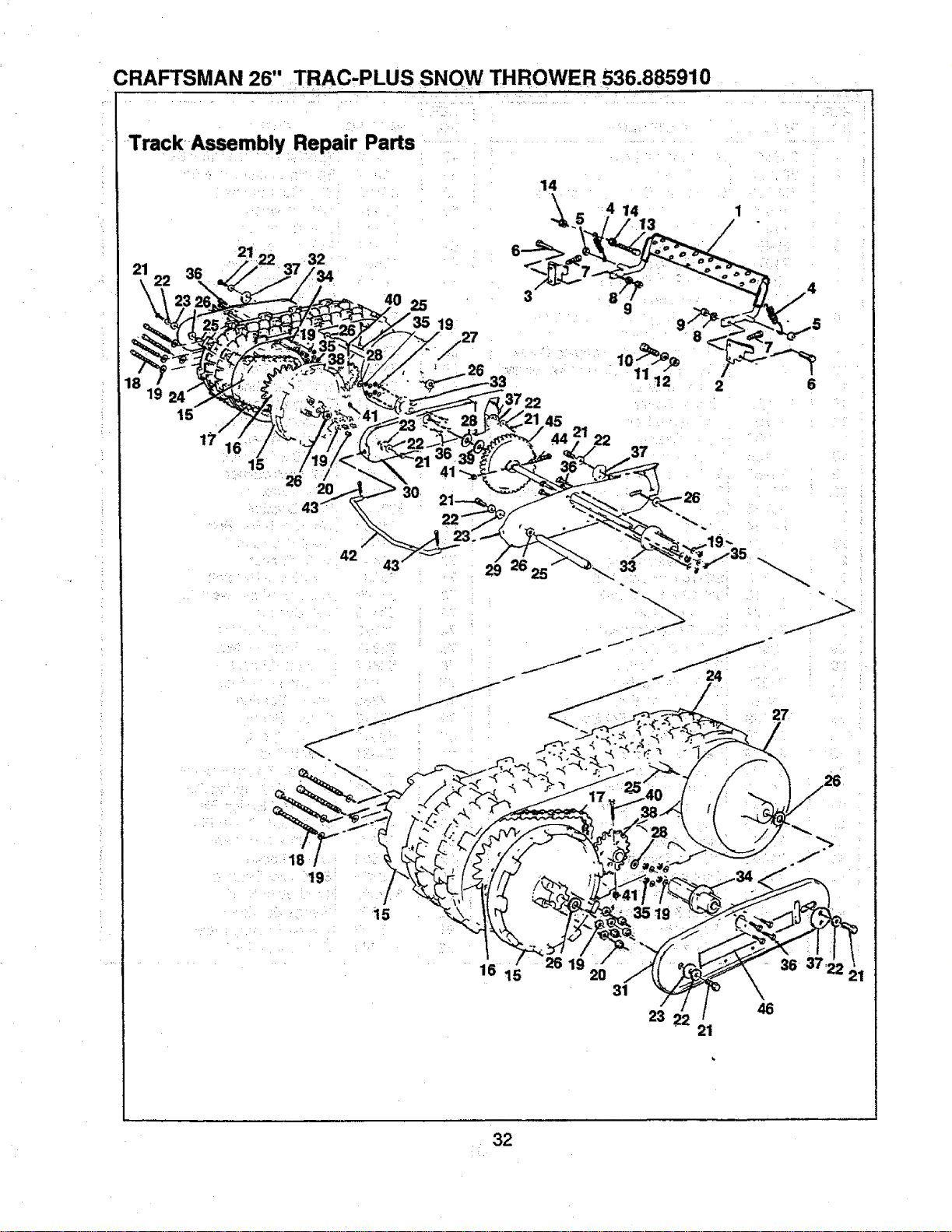
CRAFTSMAN 26" TRAC-PLUS SNOW THROWER 536.885910
Track Assembly Repair Parts
21, 32
25
19
15
./
17
15
42
29
18
19: '
15
16 15
14
2619
14 1
/
2 6
37
33
27
2O
31
23
21
36 37
46
32
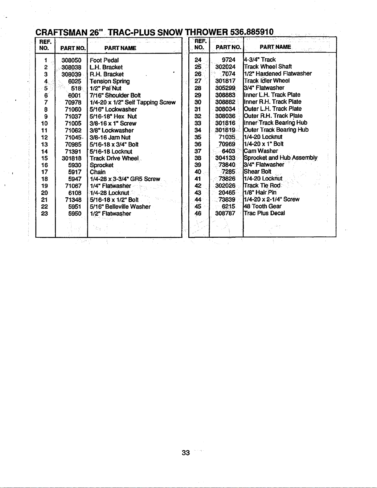
CRAFTSMAN 26,' TRAC, PLUS SNOW THRO_
REI=..................................
NO. PART NO. PARTNAME
' i
1 308050
i •
i_ 2 _.308038
3 308039_
-.: 4. i! _, 6025
6 60Ol
=
Foot Pedal
LH. Bracket
R.H. Bracket
=Tension Spring
1t2"PalNut
7/16" Shoulder Bolt
7 70978
8 71060
9 71037
10 71005
11 71062
12 71045.
13 70985
14 71391
15 301818
16 5930
17 5917
18 5947
19 71067
20 6108
21 71348
22 5951
23 5950
1/4-20 x 1/2" Self Tapping Screw
5/16" Lockwasher
5/16-18" Hex Nut
3/8-16 x 1"Screw
3/8" Lo_washer
3t8-16 Jam Nut
5/16-18 x 314"Bolt
5/16-18 Locknut
Track DriveWheel....
Sprocket
Chain
1/4-28 x3-3/4" GR5 Screw
1/4" Flatwasher _. _.. .....-
:::114-28Locknut:::: .....
5116--18rx112"Bolt . "
5/16" BellevilleWasher
1/2" Flatwasher
VER 536.885910 . ,:• ........
.,_NO. . PART---NO.. PARTNAME ..
24 :- 9724
25 ::::, 302024
26 _i_ 7074
.....27 301817
8
29 308883
30 308882 :.
31 .308034 1
32 ::308036
33 301816
34
4-3/4" Track
Track WheelShaft
t/2, Hardened Ratwasher
Track IdlerWheel
3/4" Flatwasher
Inner L.H. Track Plate
Inner R.H. Track Plate
Outer L.H. Track Plate
Outer R.H. Track Plate
InnerTrack Beadr_ Hub
35
36
37
38
39
40
30!8!9 _!Outer Track Beadng Hub
71035 .... 1t4-20 Locknut
.70969 . 1/4-20 x 1" Bolt
::......6403 __:Cam Washer
3041331: Sprocketand Hub Assembly
_:73840 3/4"Flatwasher .....
Shear Bolt
1/4-2ob:)cknm
Track TieRod: '
1/8" HairPin
1/4-20 x 2-114"Screw
48 Tooth Gear
Trac Plus Decal
7285
41 ,:::7_26
42 -. :302026:
43 i: 20465:'
:73839/
821,.-s"
46 308787 :
33 .....
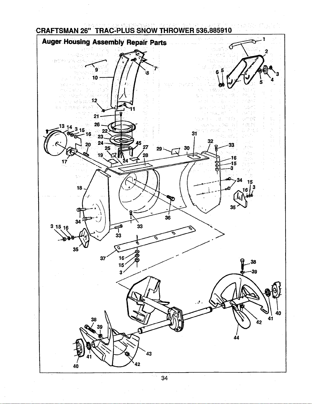
CRAFTSMAN 26" TRAC-PLUS SNOW THROWER 536.885910
Auger Housing Assembly Repair Parts
26
45
25 27 29
17
18
3 15 16 33
33
35
36
38
4O
43
42
• 1
31
32
15
3
41
34
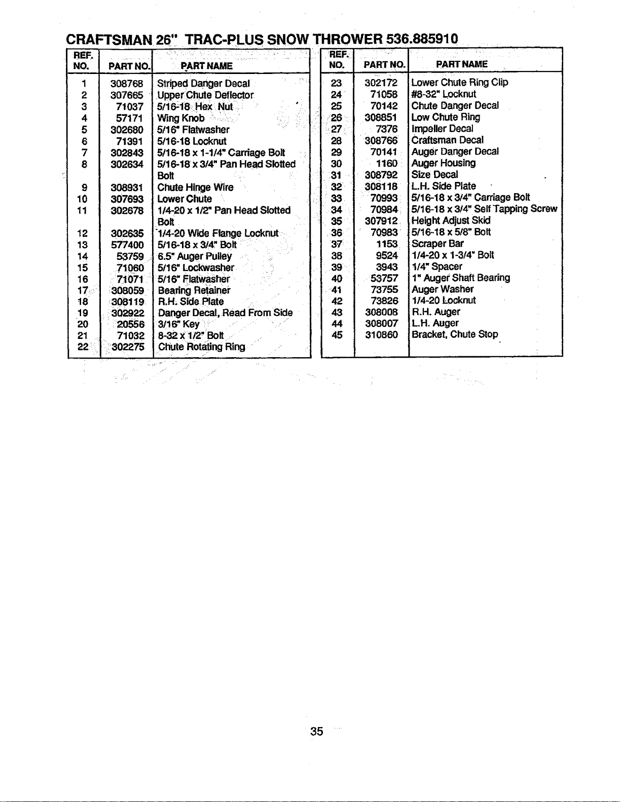
CRAFTSMAN 26, TRAC-PLUS SNOW THROWER 536.885910
RER
NO.
1
2
3
4
5
6
7
8
9
10
11
12
13
14
15
16
17/ 308059
ts 308119
19 _ 302922
• ,,.
+20 20556
21 71032
::302275
+ ,
• •...... • ............. +•• .........
PARTNO. PARTNAME
308768 StripedDanger Decal....
307665 UpperChut eDeflector
71037 5/16-18HeX :Nut .: ,
57171 Wing Knob = ......... _ 14 % "r r _ _
302680 5/16" Flatwasher L+
71391 5/16--18LOcknut
302843 5/16-18 X 1-1/4" Carriage Bolt
302634 5t16-18x 3/4" Pan Head Slotted
Bolt
308931 Chute Hinge Wire
307693 LowerChute
302678 114-20x 1/2" Pan Head Slotted
+BOR
302635 "1/4-20 Wide Flange Locknut
577400 5/16-18 x 3/4."Bolt _
53.759 _ 6.5" Auger Pulley .++
71060 5/16" Lockwasher •
• 171071 _=5/16"Fl_asher +=+i
BearingRetainer + +++
R.H; Side Plate
Danger Decal, Read From=Side
3/16" Key _" + ' "
8-32 X 1/2" BOlt ....
++
Chute RotatingRing " .+
' • ,,
NO. PART NO. " PART NAME .
+, •,
23 302172
24 71058
25 70142
, 26 : 308851
27: 7376
28 308766
29 70141
30 1160 •
i, 31 308792
I 32= 308! 18
LowerChute Ring Clip
#8-32" L.ocknut
Chute Danger Decal
Low Chute Ring
Impeller Decal
,Craftsman Decal
Auger Danger Decal
Auger Housing
Size Decal
LH. Side Plate
" 33 70993
"34 ' 70984
• 35 307912+
,36 70983
1153
38 9524
39 3943
Aft
53757
73755
42 73826
43 308008
44 308007
45 310860
5/16-18 x 3/4" Carriage Bolt
5/16-18 x 3/4" Self Tapping Screw
,Height Adjust Skid
5/16-18 x 5/8" Bolt
Scraper Bar
1/4-20 x 1-3/4" Bolt
1t/4" Spacer
1"Auger Shaft Bearing
Auger Washer
114-20 L-ocknut
R.H. Auger
LH. Auger
Bracket, ChuteStop
35
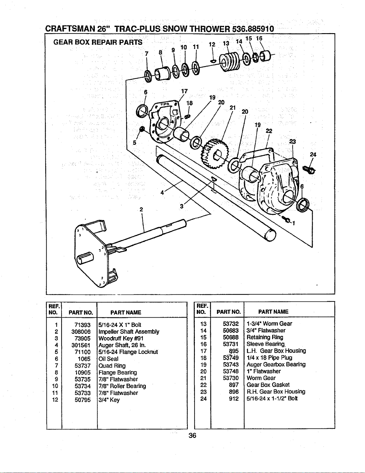
CRAFTSMAN 26" TRAC-PLUSSNOW TH ROWER 536.885910
GEAR BOX REPAIR PARTS 11 12 13 1, 15 16
7 8
6 17
19
18 20
21
2O
2
REF.
NO.
1
2
3
4
5
6
7
8
9
10
11
12
PART NO. PART NAME
71393
308006
73905
301561
71100
1065
53737
10905
53735
53734
53733
50795
5/16-24 X 1" Bolt
ImpellerShaft Assembly
WoodruffKey#91
AugerShaft, 26 In.
5/16-24 Flange Locknut
Oil Seal
Quad Ring
Flange Bearing
i7/8" Flatwasher
7t8"Roller Bearing
7/8" Flatwasher
i314"Key
REF.
NO. PARTNO. PARTNAME
13
14
15
16
17
18
19
20
21
22
23
24
36
53732
50683
50688
53731
53749
53743
53748
53730
897
896
912
1-3/4" Worm Gear
3/4" Flatwasher
RetainingRing
Sleeve Bearing.
LH. Gear Box Housing
1/4 x 18 Pipe Plug
Auger Gearbox Bearing
1" Flatwasher
Worm Gear
Gear Box Gasket
R.H. Gear Box Housing
5/16-24 x 1-1/2" Bolt
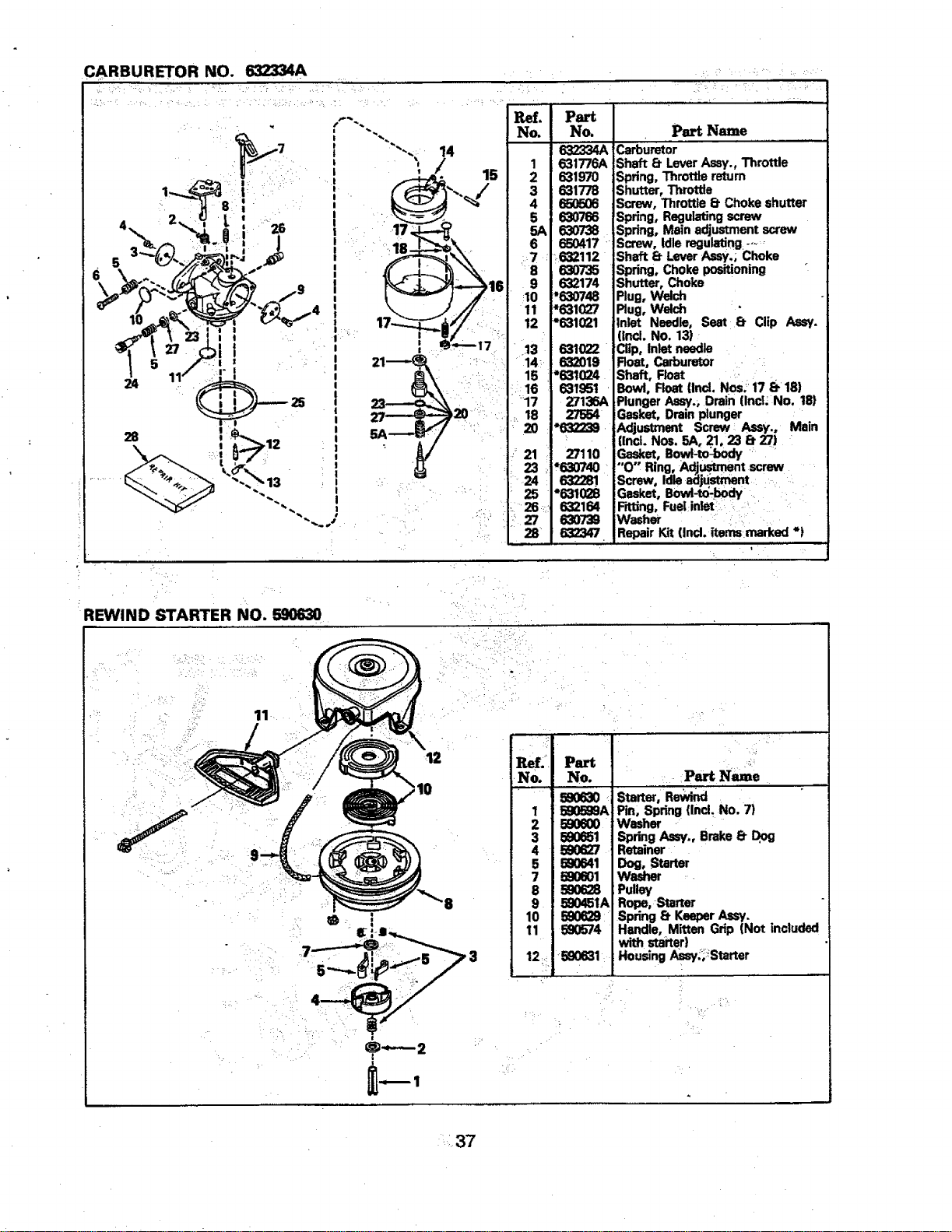
CARBURETOR NO. 632334A
• _r'_ _i+' _'_+r_ ;_'i'_ ....
4
28
+
1
I
I !
I
12
l
NO,
5
6
"'8
9
:10
11
12
' r13
+14-
15
_+16
' '17
:+2123
24 '
I_25
/ g
Part
NO.
631776A
63197O
631778
650606
63O766
63O738
650417 +
632112
63O735
632174
*630748
"631027
"631021
_1022
632019
*_I_4
_I_1
_136A
27554
_132239
_110
,6307_
632281.
*_1028
6321_
63O7'39
632347
Part Name
Carburetor .....
Shaft £t LeverAssy., Throttle
Spring. Throttlereturn
Shutter, Throttle
Screw, Throttle _ Choke shutter
Spring, Regulatingscrew
Spdng, Main adjustmentscrew
Screw, Idleregulating,--_,
Shaft 8- LeverAssy,; Choke
Spring, Choke positioning
Shutter, Choke
Plug,Welch
Plug,Welch
Inlet Needle, Seat 8. Clip Aasy,
(ind. No. 13)
Clip, Inlet needle
Roat, Carburetor ,
Shaft, Float , +
Bowl, Float [Incl. Nos: 178-18)
PlungerAssy, Drain (Incl. No, 18)
Gasket. Drainplunger
Adjustment Screw Assy., Main
|incl. Nos. 5A, 21, 23 8. 27)
..G_€,et,Bowl-to_oody+ '
"'O Ring, Adj.u_rne_ntscrew
Screw, Idleadjustment....
Gasket, Bowl-lx_-body
F_lJng,Fuelinlet '
Washer + : ,: +,
RepairKit (Ind. itemsmarked *)
REWIND STARTER NO. 590630
.12
:10
i
ReL. Part '..,_....
No, No. , Part Name
ss0_0 +Starte_,Rewi_
I 590599A Pin, Spring (IncL No. 7)
2 580600 Washer +
3 590651 Spring Assy,, Brake 8. Dog
4 580627 Retainer
5 5_641 WDoga_tarter
590628 Pulley
9 5g0451A Rope, Starter
10 590629 Spring 8- KeeperAssy.
1211_59083590574withHandle'starter)MittenGrip (Not included
Housing Assy_,iStarter
mt ;
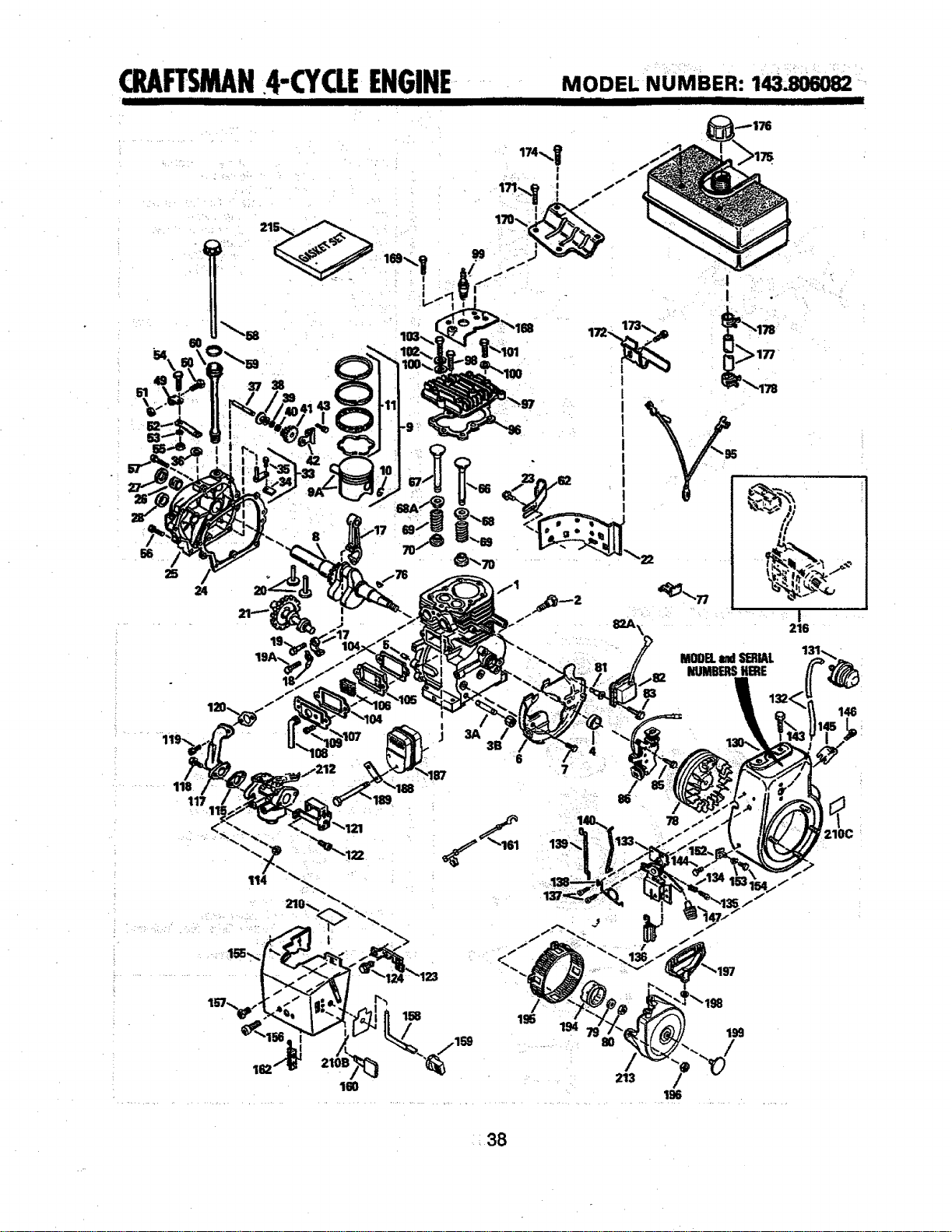
k
CILAFTSMAN.4-CYCLEENGINE MODELNUMBER:143_
I I IIIII I H III I ILIIIL IIII
B1
66
25
24
118
117
19A.
114
!
!
|
I
139
I
I
78
i
216
MODELu4 SI_IAL
NUMBERSHERE
t46
210C
¥
162
160
194
213
/
196
199
38
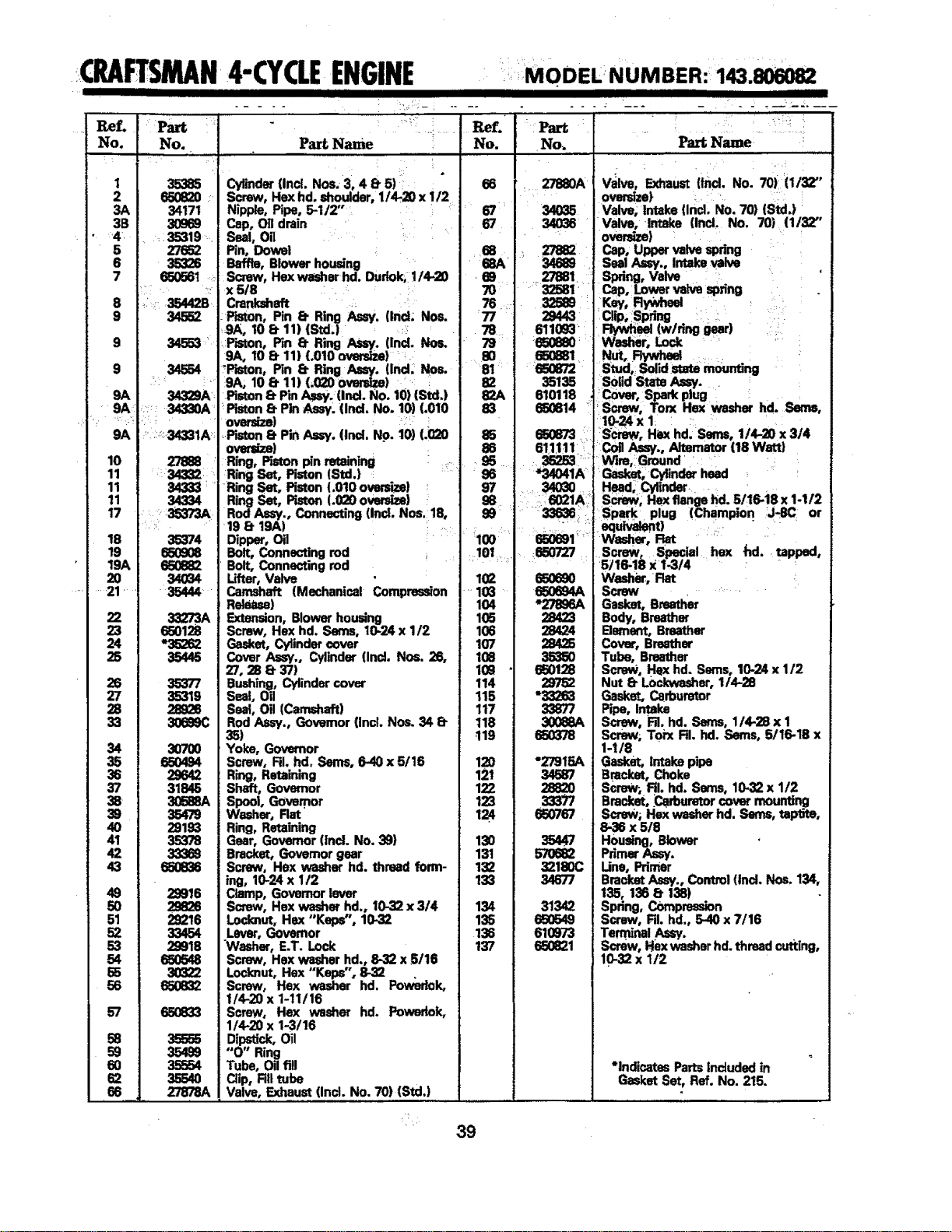
(RAFTSMAN4"CYCLEENGINE MODELNUMBER:143.806082
No. No.
1 35385
2 650_Z0
3A 34171
3B 30869
• 4 : 35319
5 27652
6 35326
7 650561
8 35442B
9 34_2
9 3_3 ¸_¸
9 34554
9A 34329A
9A 'r:r' 34330A'
9A ::::_34331A:
10
11
11
11
17
18
19
19,6,
20
21
22
23
34
35
38
43
49
5O
51
52
53
54
65
56
57
l_'f,
Part Name , No.
Cylinder(incl. Nos. 3; 4 8- 5)::: 66
Screw, Hex hd. shoulder, I14-20 x 112
Nipple,Pipe, 5-112..... ..... 67
Cap, Oil drain 67
Seal, Oil
Pin, Dowel .... 68
Baffle, Blowerhousing
Sinew, Hexwasherhd. Dudok, 1/4.20
x 5/R
Crankshaft
-Piston, Pin 8. Ring Am/. (IncL Nos.
9A, 10 8. 11) (Std,) :::
.F_ton, Pin 8. Ring As=y. (Ind. Nos.
9A, 10 8. 11) (.010 oversize) :_
:Piston, Pin 8. Ring Assy. (Ind, Nos.
9A, 10 8. 11) L020 ovmsize)
,Piston 8. Pin A=_. (incl. No. 10)(Std.)
"Piston 8" PinAssy. (Ind. No. 10) (.010
oversize] ......
_.piston8. Pin Assy. (incl. No. 10) (.020
Paxt Name:
•Part •
No_
:, 27880A Valve, Exfraust(ind, No. 70):(1132"
oversize) •
34035 Valve; intake {incl. No. 70) (Std,)
34036 _Valve, Intake (Incl. No. 70) (1132"
' oversize)
. 27882 Cap, Uppervalvespdng
68A 34689 Seal Assy., Intake valva
•69 ,27881 : Spring, Valve
7O
32581 Cap, Lowervalvespring
32_9 :
,Kw,Rywhe¢ •
,77_-,
29443 Clip, :Spring : : ,
Rywheel(w/ring gearj
,=, Wader, Lock
80 650881 Nut, !:lywhecl • . . '
81 650872 Stud, Solid.statemounting
82 35135 :Solid State Assy. ,
82A 610118 Cover, Spa_piug hd "
83 650814 r__S_ , TOn( HeX washer . crams,
10-24x I
650873 ' :screw, Hexhd. Semso1/4-20x314
Coil Assy., Altemator (18 Watt}
rWire,/Ground •
Gasket, Cylinderhead L
Head,Cylinder •
Screw, Hexflange hal.5116-18 x 1-1/2
Spark plug (Champion :J._C or
Washer, Rat .....
Screw, Special he)( hd, tapped,
5116-18 X 1-3/4 L
85
58
59
60
62
68
27888
34334
35374
680808
65O882
ove_) • 86 611J11: i
Ring, Piston pin retaining : ....... 95 .... _ .....
Ring Set, Piston (Std.} .... 86 "34041A
Ring Set, Piston(.010 oversize) _ 97 3A03O
RingSet, Piston(.020 ovmsizs} - 98 .; 6021A _
RodAuy., Connecting(incl. Nos.18, 89 ....... 33636 1
198" 19A) : r _ .__ [ _, _ L : _
Dipper,Oil luu _,
BOlt,Connectingmd , 101 850727
Bolt, Connecting rod
34034
35273A
65o128
*35262
35446
35377
35319
28_8
30_9C
3O7OO
66O494
29642
31845
30688A
35479
28193
35378
33369
65O836
29916
28826
29216
33454
29918
65O548
3O322
65O832
65O833
35555
35489
-35654
35540
27978A.
Lifter, Valve
Camshaft (Mechanical Compression
Release)
sxtansion,Blowerhou=in
Screw, Hex hd. Seres, x 112
Gasket, Cylindercover
Cover Ass'/,, Cylinder (Ind. Nos. 26,
27,288.37)
Bushing, Cylindercover
Seal, Oil
Seat, Oil (Camshaft)
RodAssy., Governor(Incl. Nos. 34 B-
35)
Yoke, Governor
Screw, RI. hd. Seres,6-40 x 5t16
Ring, Retaining
Shaft, Governor
Spool, Governor
Washer, Rat
Ring, Retaining
Gear, Governor(incl. No. 39)
Bracket, Govemor gear
Screw, Hex washer hd. thread form-
ing, 10-24x 1/2
Clamp, Govemor lever
Screw, Hex washer hd., 10-32x 314
Locknut, Hex "Keps", 10-32
Lever,Governor
Washer, E.T. Lock
Screw, Hex washer hd., 8-32 x 5/16
Locknut, Hex "Keps'; 8-32
Screw, Hex washer hd. Pow;sdok,
1/4-20 x 1-11/16
Screw, Hex washer hd. Powedok,
1/4-20 x 1-3116
Dipstick,Oil
"O" Ring
Tube, Oilfig
Clip, RII tube
Valve, Exhaust (Incl. No. 70) (Std.)
103 .... 650684A
104 "27896A
105 28423
106 28424
107 28425
108 3535O
168 65O128
114 29752
115 "33283
117 33877
118 30068A
!19 650378
120 "279!5A
121 34687
122 28820
123 33377
124 650767
130 35447
131 570682
132 32180C
133 34677
134 31342
135 650549
135 610973
137 650821
Washi_.,Rat
Screw :: •
Gasket, Breather
Body, Breather
Bement, Breather
Cover, Breather
Tube, Breather
Screw, Hex hd. Sems, 10-24 x 112
Nut 8- L0ckwasher,114.28
Casket, Carburetor
Pipe, Intake
Screw, RI. hd. Serns, 114-28x 1
Scrm_,Toix RI. hd. Serns, 5116-18x
1-t/8
Gasket, Intake
Bracket, Chokepipe
Screw; RI. hd. Seres, 10-32x 112
Bracket,:Carburetorcover mounting
Screw; Hex washerhd. Seres,taptlte,
8-36 x 518
Housing, Blower
PrimerAssy.
Une, Primer
BracketAssy.,Control (Ind. Nos. 134,
135, 1358 135)
Spdng, Compression
Screw, RI. hd., 5-40 x 7/16
Termfi'nalAs=y,
Screw, Hexwasher hd.thread cutting,
10-32x 112
*indicates Partsinduded in
Gasket Set, Ref. No. 215.
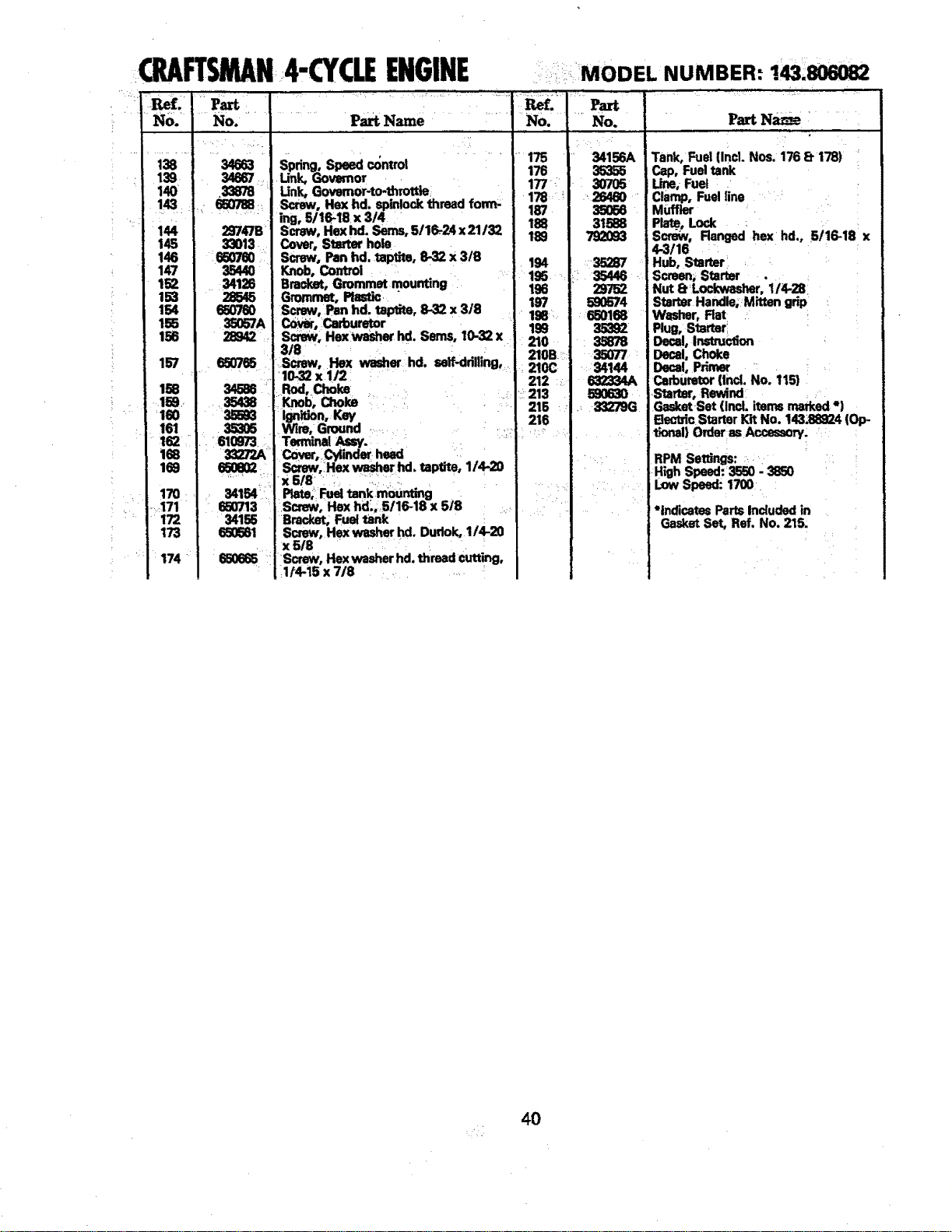
Q AFTSMAN4"CYCLEENGINE
!,
139r
140
144
145
146
147
152
153
154
155
156
157
It
160
161
162 _
168
169
170
....:171
172
173
174
MODEL NUMBER: !43.806082
No.
29747B:
33013
:650"_0
3544O
3412S
_57A
650765
r_
34154_;:_:
650713 :
34155
65O581
:650665
Pa_ Name No. ]
Spdng, Speed contro| .... 176 1
unk,Qo mo, , I
Unk, Governor-to-throttle. _ _ ;
Screw, He](hd, Sl_lock thread form- 187 i
ing, 5/16-.18 x 3/4
Screw, Hexhd. Sems,5/16-24 x21/32 188 I
Cover,Starter hole 18S
Screw, Panhd. taptite, 8-32 x 3/8 194
Knob, Control 195
BrackBt,Grommet mounting 196
Grommet, Plastic. " 197
Screw, Panhd. taptite, 8-32 x 318 198:.
C0wr, Cafouretor
_, Hexwasher hd. Seres, t0--_ x 199
...... 210
318 ....
Screw, Hex washer hd, seif-ddlUng,. 210B
• 210C
10-32 xl/2 212 .:
Rod,Choke .
Knob, Choke • _ : 213
• 215
Ignition, Key 216
Wire, Ground ..... ._- .
Terrn'malA_y.
_, r _ head •
Sctew,iHexwasherhd.taptite,I/4-20
x618 . :,: :,, . .....
Plate; Fueltank mounting 18
Screw, Hex hd:;.5/16-18 x 5 :. .
Bracket, Fuel tank
Screw, Hex washerhd, Dudok, 1/€20
x 5/8 : '
Screw, Hexwasherhd. threadcutting,
:11_15 x 718 ......
Part
34156A
35355
307O5
26460
35058
31588
792O93
35287
35446
29752
590574
550168
35382
35878
35077
54144
632334A
590630
33279G
Part Na_ze
Tank, Fuel (incl.Nos. 176 8 173)
Cap, Fuel tank
Line,-Fuel :
Clamp, Fuel line
Muffler
Pla__,Lock
Scr_v, Ranged hex hd., 5/16-18 x
4-3/16
Hub, Starter
Screen, Starter .
Nut I_:Lockwasher,t/4-28
StarterHandle;Mitten grip
Washer, Rat
Plug,Starter:
Decal,Instruction
Decal,Choke
Decal, Primer
Carburetor(IncLNo. 115)
Starter, Rewind
Gasket-Set(Incl. itemsmarked*)
Bectric StarterKit No. 143;88924(Op-
t_rml) Order asAccassow.
RPMSeffings:
LowSpeed:1700
*indicates Parts Included in
Gasket Set, Ref. No. 215.
40

NOTES .........................................
m, j i m , j ....
H
41
.......NOTES
NOTES
43
,,,,,,,,,,,,,,,,,,,,,,,,,,,,,,,,,,,,,,,,
OWNER'S
MANUAL
MODEL NO.
536.885910
HOW TO ORDER
REPAIR PARTS
£RRFTSMAN
8 HORSEPOWER
26" DUAL STAGE
TRAC-PLUS
120V. ELECTRIC START
=
SNOW THROWER
Each SNOW THROWER has its own MODEL
NUMBER found on the motor mount frame.
Each ENGINE has its own MODEL NUMBER
found on the BLOWER HOUSING.
Always mentionthese MODEL NUMBERS when
requesting service or Repair Parts foryourSNOW
THROWER.
All parts listed herein may be ordered through
any Sears Service CenterlDepartme ntand most
Sears Stores.
WHEN ORDERING REPAIR PARTS, ALWAYS
GIVE THE FOLLOWING INFORMATION:
* PRODUCT- "SNOW THROWER"
MODEL NUMBER - 536.885910
* ENGINE MODEL NUMBER 143.806082
* PART NUMBER
* PART DESCRIPTION
"YourSears merchandisehas added valuewhen you
considerthatSears has service unitsnationwidestaffed
withSears trainedtechn'_-ians...Professionaltechnicians
specificallytrained on Sears Products,havingthe parts,
toolsand equipmentto insurethatwe meet ourpledge
toyou...we servicewh_{tWe sell."
SEARS, ROEBUCK AND CO.
307145 09/26/90
, Chicago, IL 60684
Printed in U,S.A.