Loading ...
Loading ...
Loading ...
SERVmCEAND ADJUSTMENTS
i
11m =H mini =liiN,i, i, 1,1 ,1,,,,,,, ,,m ,=,,,,,r=
CAUTION; BEFORE PERFORMING ANY SERVICE OR ADJUSTMENTS:
• Depress clutch/brake pedal fully and set parking brake.
• Place gearshift lever in "NEUTRAL" position.
. Place attachment clutch in "DISENGAGED" position.
• Turn ignition key"OFF" and remove key.
• Make sure the blades and all moving parts have completely stopped.
• Disconnect spark plug wire from spark plug and place wire where it cannot come in contact with
plug.
TRACTOR
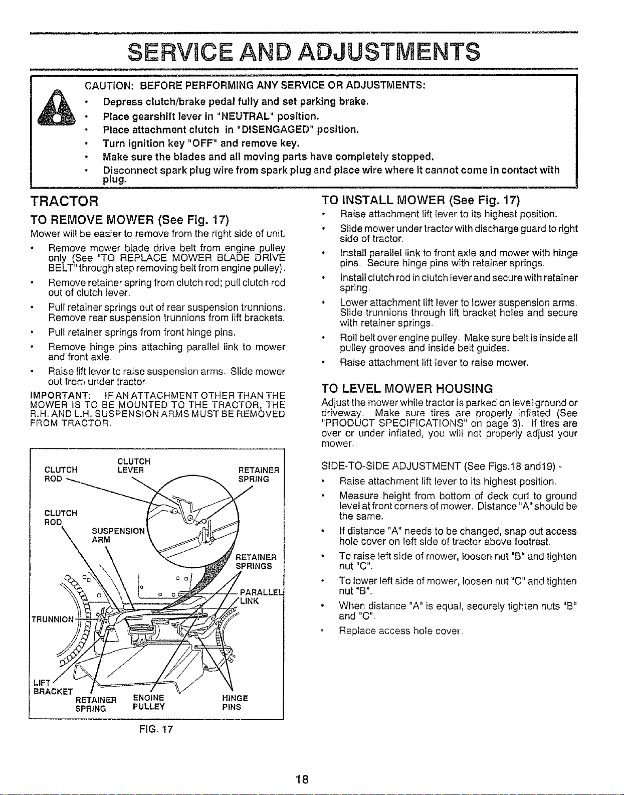
TO REMOVE MOWER (See Fig. 17)
Mower will be easier to remove from the right side of unit°
• Remove mower blade drive belt from engine pulley
only !See TO REPLACE MOWER BLADE DRIVE
BELT' through step removing belt from engine pulley).
• Remove retainer spring from clutch rod; pull clutch rod
out of clutch lever
• Pull retainer springs out of rear suspension trunnions.
Remove rear suspension trunnions from lift brackets
• Pull retainer springs from front hinge pins.
• Remove hinge pins attaching parallel link to mower
and front axle
Raise lift lever to raise suspension arms, Slide mower
out from under tractor,
IMPORTANT: IF AN ATTACHMENT OTHER THAN THE
MOWER IS TO BE MOUNTED TO THE TRACTOR, THE
R.H.AND L,H. SUSPENSION ARMS MUST BE REMOVED
FROM TRACTOR,
TO INSTALL MOWER (See Fig. 17)
• Raise attachment lift lever to its highest position.
• Slide mower under tractor with discharge guard to right
side of tractor
• Install parallel link to front axle and mower with hinge
pins Secure hinge pins with retainer springs°
• Install clutch rod in clutch lever and secure with retainer
spring,
• Lower attachment lift lever to lower suspension arms.
Slide trunnions through lift bracket holes and secure
with retainer springs
. Roll belt over engine pufley. Make sure belt isinside all
puliey grooves and inside heft guides.
• Raise attachment lift lever to raise mowerr
TO LEVEL MOWER HOUSING
Ad ust the mower while tractor is parked on Ievel ground or
dr veway. Make sure tires are properly inflated (See
"PRODUCT SPECIFICATIONS" on page 3). If tires are
over or under inflated, you wilt not properly adjust your
mower.
CLUTCH
CLUTCH LEVER
ROD
CLUTCH
ROD
SUSP ENSION
RM
rRu °NNI_
LIFT I
BRACKET I
RETAINER ENGINE
SPRING PULLEY
RETAINER
SPRING
_AINER
SPRINGS
JPARALLEL
LINK
HINGE
PINS
SIDE-TO-SIDE ADJUSTMENT (See Figs.18 and19) -
• Raise attachment lift lever to its highest position.
• Measure height from bottom of deck curl to ground
level at front corners of mower, Distance "A" should be
the same.
• If distance "A" needs to be changed, snap out access
hole cover on left side of tractor above footrest.
o To raise left side of mower, loosen nut "B" and tighten
nut "C".
To lower left side of mower, loosen nut "C" and tighten
nut "B",
When distance "A" is equal, securely tighten nuts "B"
and "C'L
Replace access hole cover,
FIG. t7
t8
Loading ...
Loading ...
Loading ...