Loading ...
Loading ...
Loading ...
EN
17
Installation
www.bora.com
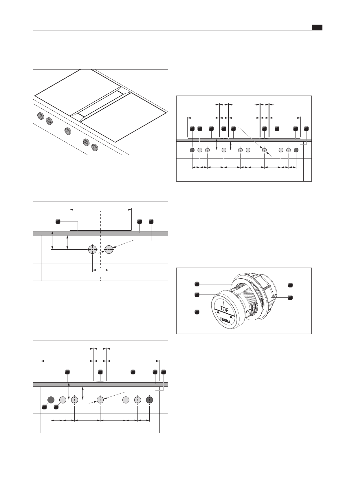
[1] Boreholes for socket (x 2 external)
[2] Bore holes for control knobs (x 5)
[3] Cooktop (x 2)
[4] Cooktop extractor
[5] Worktop
[6] Fixed front panel
≥70 ≥40
90 90 909090 196 196 196 196
370 370
370
110
1 1 1 1
110
Ø50 ±0,5
3
3
1 2 4 4 3 65
Fig. 5.12 Drilling pattern for 3 cooktops, 2 cooktop extractors
and 2 sockets
[1] Boreholes for socket (x 2 external)
[2] Bore holes for control knobs (x 8)
[3] Cooktop (x 3)
[4] Cooktop extractor (x 2)
[5] Worktop
[6] Fixed front panel
5.6.3 Fitting the control knob
4
3
5
2
1
Fig. 5.13 Structure of control knob
[1] Knob housing
[2] Universal nut
[3] Sticker
[4] Knob ring
[5] Wave spring
i
In the case of steel fronts, wave springs must not be used.
The corresponding installation steps are to be omitted.
5.6 Installing the control knob in the
floor unit front panel
Fig. 5.9 Installed control knob
XX
Pre-drill all bore holes to prevent tearing out the fixed front panel.
5.6.1 Cooktop bore holes
≥40≥70
Ø50 ±0,5
370
80-140
1 2 3
Fig. 5.10 Cooktop drilling pattern
[1] Cooktop
[2] Worktop
[3] Fixed front panel
5.6.2 Example bore holes
≥40≥70
90 90 90
Ø50 ±0,5
90 196 196
370 370
110
1 1
3
1 2
4 3 65
Fig. 5.11 Drilling pattern for 2 cooktops, 1 cooktop extractor
and 2 sockets
Loading ...
Loading ...
Loading ...