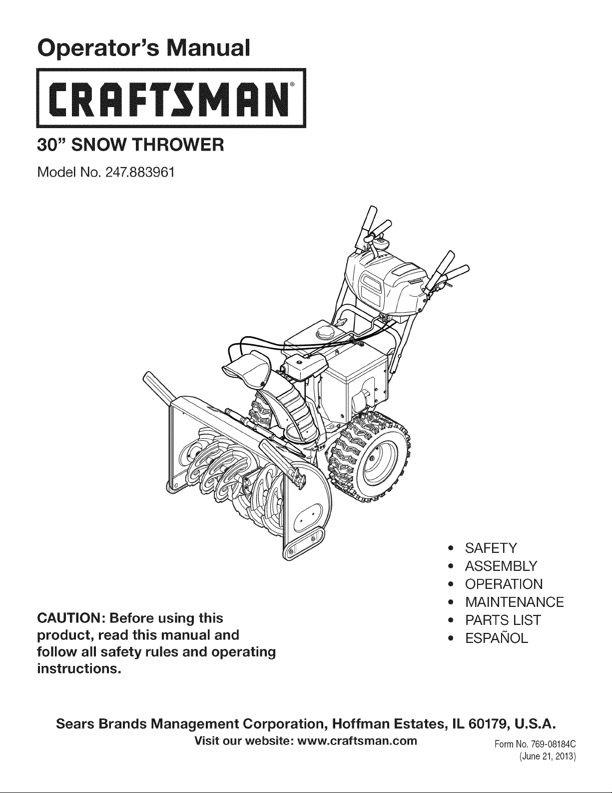
Operator's Manual
CRRFr MRN
30" SNOW THROWER
Model No. 247.883961
CAUTION" Before using this
product, read this manual and
follow all safety rules and operating
instructions.
,, SAFETY
o ASSEMBLY
OPERATION
MAINTENANCE
PARTS LIST
o ESPANOL
Sears Brands Management Corporation, Hoffman Estates, IL 60179, U.S.A.
Visit our website: www.craftsman.com FormI/o 769-08184C
(June21,2013)

WarrantyStatement.............................. Page2
SafeOperationPractices...................... Pages3-6
Assembly.................................... Pages8-12
Operation.................................. Pages13-17
Service&Maintenance...................... Pages18-23
Off-SeasonStorage............................. Page24
Troubleshooting............................... Page26
PartsList................................... Pages28-44
RepairProtectionAgreement.................... Page47
Espa_ol........................................ Page48
CRAFTSMANTWOYEARFULLWARRANTY
FORTWOYEARSfromthedateof purchase,this productiswarrantedagainstanydefectsinmaterialorworkmanship.Defectiveproductwill receivefree
repairorfreereplacementif repairisunavailable.
ADDITIONALLIFETIMELIMITEDWARRANTYon UPPERand LOWERCHUTE
FORASLONGASITISUSEDbytheoriginalownerafterthesecondyearfromthedateofpurchase,theupperandlowerchuteofthissnowthrowerare
warrantedagainstanydefectsinmaterialorworkmanshipasverifiedbyaSearsauthorizedserviceprovider.Withproofofpurchase,youwill receivea new
chutefreeofcharge.Youareresponsiblefor thelaborcostofinstallationandanycostincurredto verifythedefect.
Forwarrantycoveragedetailsto obtainrepairorreplacement,visitthewebsite:www.craftsman.com
ThiswarrantycoversONLYdefectsinmaterialandworkmanship.WarrantycoveragedoesNOTinclude:
• Expendableitemsthatcanwearoutfrom normalusewithinthewarrantyperiod,includingbutnotlimitedto augers,augerpaddles,drift cutters,skid
shoes,shaveplate,shearpins,sparkplug,air cleaner,belts,andoilfilter.
• Standardmaintenanceservicing,oilchanges,ortune-ups.
• Tirereplacementorrepaircausedbypuncturesfrom outsideobjects,suchasnails,thorns,stumps,orglass.
• Tireor wheelreplacementorrepairresultingfrom normalwear,accident,or improperoperationormaintenance.
• Repairsnecessarybecauseofoperatorabuse,includingbutnot limitedto damagecausedbyover-speedingtheengine,orfrom impactingobjectsthat
bendtheframe,augershaft,etc.
• Repairsnecessarybecauseofoperatornegligence,includingbutnot limitedto, electricalandmechanicaldamagecausedbyimproperstorage,failureto
usethepropergradeandamountofengineoil,orfailureto maintaintheequipmentaccordingto theinstructionscontainedinthe operator'smanual.
• Engine(fuelsystem)cleaningorrepairscausedbyfueldeterminedto becontaminatedoroxidized(stale).Ingeneral,fuelshouldbeusedwithin 30days
ofitspurchasedate.
• Normaldeteriorationandwearoftheexteriorfinishes,or productlabelreplacement.
Thiswarrantyisvoidif thisproductiseverusedwhileprovidingcommercialservicesorif rentedto anotherperson.
Thiswarrantygivesyouspecificlegalrights,andyoumayalsohaveotherrightswhichvaryfromstateto state.
SearsBrandsManagementCorporation,NoffmanEstates,IL60179
Engine Oil: 5W-30
Fuel: Unleaded Gasoline
Engine: MTD
Model Number
Serial Number
Date of Purchase
Record the model number, serial number,
and date of purchase above.
© Sears Brands, LLC 2
Thissymbolpointsout importantsafety instructionswhich, if not
followed, couldendangerthe personalsafetyand/or property of
yourself and others.Readandfollow all instructions in this manual
beforeattempting to operatethis machine.Failureto complywith these
instructionsmay resultinpersonalinjury.Whenyou seethis symbol, HEED
ITSWARNING!
CALIFORNIA PROPOSITION 65
EngineExhaust,someof its constituents,and certainvehiclecomponents
containor emit chemicalsknownto Stateof Californiato causecancerand
birth defectsorother reproductiveharm.
Thismachinewas built to beoperatedaccordingto thesafeoperation
practicesinthis manual.Aswith anytype of powerequipment,
carelessnessorerror on the part of the operatorcanresultinseriousinjury.
Thismachineiscapableof amputating fingers, hands,toesandfeet and
throwingdebris.Failureto observethefollowing safety instructionscould
resultin seriousinjuryor death.
Your Responsibility--Restrict the useof this powermachineto
personswho read, understandandfollow the warningsand instructionsin
this manualandon the machine.
SAVETHESEINSTRUCTIONS!
TRAINING
Read,understand,andfollowall instructionsonthemachineandinthe
manual(s)beforeattemptingto assembleandoperate.Failureto dosocan
resultinseriousinjury totheoperatorand/orbystanders.Keepthis manual
inasafeplaceforfutureandregularreferenceandfororderingreplacement
parts.
Befamiliarwith all controlsandtheir properoperation.Knowhowto stop
themachineanddisengagethemquickly.
Neverallowchildrenunder14yearsof ageto operatethis machine.Children
14andovershouldreadandunderstandthe instructionsandsafeoperation
practicesinthis manualandonthemachineandbetrainedandsupervised
byanadult.
Neverallowadultsto operatethismachinewithout properinstruction.
Thrownobjectscancauseseriouspersonalinjury.Planyoursnow-throwing
patternto avoiddischargeof materialtowardroads,bystandersandthelike.
Keepbystanders,petsandchildrenat least75feetfromthe machinewhileit
isin operation.Stopmachineif anyoneentersthe area.
Exercisecautionto avoidslippingorfalling, especiallywhenoperatingin
reverse.
PREPARATION
Thoroughlyinspecttheareawheretheequipmentisto beused.Removeall
doormats,newspapers,sleds,boards,wiresandotherforeignobjects,which
couldbetrippedoverorthrownbytheauger/impeller.
Alwayswearsafetyglassesor eyeshieldsduringoperationandwhile
performinganadjustmentor repairto protectyoureyes.Thrownobjects
whichricochetcancauseseriousinjuryto theeyes.
Donotoperatewithout wearingadequatewinteroutergarments.Donot
wearjewelry,longscarvesorotherlooseclothing,whichcouldbecome
entangledinmovingparts.Wearfootwearwhichwill improvefooting on
slipperysurfaces.
Usea groundedthree-wireextensioncordandreceptacleforall machines
with electricstartengines.
Disengageall controlleversbeforestartingtheengine.
Adjustcollectorhousingheightto cleargravelorcrushedrocksurfaces.
Neverattemptto makeanyadjustmentswhileengineisrunning,except
wherespecificallyrecommendedintheoperator'smanual.
Letengineandmachineadjustto outdoortemperaturebeforestartingto
clearsnow.
Safe Handling of Gasoline:
Toavoid personalinjuryor property damageuseextreme carein handling
gasoline.Gasolineisextremely flammableandthe vaporsareexplosive.
Seriouspersonalinjurycan occurwhengasolineis spilledonyourselfor your
clotheswhichcanignite. Washyour skinandchangeclothesimmediately.
Useonlyanapprovedgasolinecontainer.
Neverfill containersinsidea vehicleorona truckor trailerbedwitha plastic
liner.Alwaysplacecontainersonthegroundawayfrom yourvehiclebefore
filling.
Whenpractical,removegas-poweredequipmentfrom thetruckor
trailer andrefuelit onthe ground.Ifthisis notpossible,thenrefuelsuch
equipmenton atrailerwith aportablecontainer,ratherthanfromagasoline
dispensernozzle.
Keepthenozzleincontactwith therim ofthefuel tankorcontaineropening
at alltimesuntil fuelingiscomplete.Donotusea nozzlelock-opendevice.
Extinguishall cigarettes,cigars,pipesandothersourcesof ignition.
Neverfuel machineindoors.
Neverremovegascapor addfuel whilethe engineishotorrunning.Allow
engineto coolat leasttwo minutesbeforerefueling.
Neveroverfill fueltank.Filltankto nomorethan1/2inchbelowbottomof
filler neckto allowspacefor fuelexpansion.
Replacegasolinecapandtightensecurely.
Ifgasolineisspilled,wipeit offthe engineandequipment.Moveunitto
anotherarea.Wait.5minutesbeforestartingtheengine.
Toreducefirehazards,keepmachinefreeofgrass,leaves,orotherdebris
build-up.Cleanupoilorfuelspillageandremoveanyfuelsoakeddebris.
Neverstorethemachineorfuelcontainerinsidewherethereisanopen
flame,sparkorpilotlightasonawaterheater,spaceheater,furnace,clothes
dryerorothergasappliances.
OPERATION
Donotput handsorfeetnearrotatingparts,inthe auger/impellerhousing
orchuteassembly.Contactwith therotatingpartscanamputatehandsand
feet.
Theauger/impellercontrolleverisasafetydevice.Neverbypassits
operation.Doingsomakesthemachineunsafeandmaycausepersonal
injury.
Thecontrolleversmustoperateeasilyin bothdirectionsandautomatically
returnto thedisengagedpositionwhenreleased.
Neveroperatewith amissingor damagedchuteassembly.Keepall safety
devicesinplaceandworking.
Neverrunanengineindoorsor inapoorlyventilatedarea.Engineexhaust
containscarbonmonoxide,anodorlessanddeadlygas.
Donotoperatemachinewhileundertheinfluenceof alcoholor drugs.
Mufflerandenginebecomehot andcancauseaburn.Donottouch.Keep
childrenaway.
Exerciseextremecautionwhenoperatingonor crossinggravelsurfaces.Stay
alertforhiddenhazardsortraffic.
Exercisecautionwhenchangingdirectionandwhileoperatingonslopes.Do
notoperateon steepslopes.
Planyoursnow-throwingpatternto avoiddischargetowardswindows,
walls,carsetc.Thus,avoidingpossiblepropertydamageorpersonalinjury
causedbyaricochet.
Neverdirectdischargeat children,bystandersandpetsor allowanyonein
front of themachine.
Donotoverloadmachinecapacitybyattemptingto clearsnowat toofastof
arate.
Neveroperatethismachinewithoutgoodvisibilityorlight. Alwaysbesureof
yourfootingandkeepafirm holdonthe handles.Walk,neverrun.
Disengagepowerto the auger/impellerwhentransportingor not in use.
Neveroperatemachineat hightransportspeedsonslipperysurfaces.Look
downandbehindandusecarewhenbackingup.
If themachineshouldstartto vibrateabnormally,stoptheengine,
disconnectthe sparkplugwire andgroundit againsttheengine.Inspect
thoroughlyfordamage.Repairanydamagebeforestartingandoperating.
Disengageall controlleversandstopenginebeforeyouleavetheoperating
position(behindthehandles).Waituntil the auger/impellercomesto
acompletestopbeforeuncloggingthechuteassembly,makingany
adjustments,orinspections.
Neverputyourhandin the dischargeorcollectoropenings.Donot unclog
chuteassemblywhile engineis running.Shutoff engineandremainbehind
handlesuntil allmovingpartshavestoppedbeforeunclogging.
Useonlyattachmentsandaccessoriesapprovedbythemanufacturer(e.g.
wheelweights,tirechains,cabsetc.).
Whenstartingengine,pull cordslowlyuntil resistanceisfelt, thenpull
rapidly.Rapidretractionofstartercord(kickback)will pullhandandarm
towardenginefasterthanyoucanletgo. Brokenbones,fractures,bruisesor
sprainscouldresult.
Ifsituationsoccurwhicharenot coveredinthismanual,usecareandgood
judgment.
CLEARING A CLOGGED DISCHARGE CHUTE
Handcontactwith therotatingimpellerinsidethedischargechuteisthe most
commoncauseof injuryassociatedwith snowthrowers.Neveruseyourhandto
cleanout thedischargechute.
Toclearthe chute:
a. SHUTTHEENGINEOFF!
b. Wait 10secondsto besurethe impellerbladeshavestopped
rotating.
c. Alwaysuseaclean-outtool,not yourhands.
MAINTENANCE & STORAGE
Nevertamperwith safetydevices.Checktheirproperoperationregularly.
Referto themaintenanceandadjustmentsectionsof thismanual.
Beforecleaning,repairing,or inspectingmachinedisengageall control
leversandstoptheengine.Waituntil theauger/impellercometo acomplete
stop.Disconnectthesparkplugwire andgroundagainsttheengineto
preventunintendedstarting.
Checkboltsandscrewsforpropertightnessat frequentintervalsto keepthe
machineinsafeworkingcondition.Also,visuallyinspectmachineforany
damage.
Donotchangetheenginegovernorsettingorover-speedtheengine.The
governorcontrolsthemaximumsafeoperatingspeedof theengine.
Snowthrowershaveplatesandskidshoesaresubjectto wearanddamage.
Foryoursafetyprotection,frequentlycheckallcomponentsandreplace
with originalequipmentmanufacturer's(OEM)partsonlyaslistedinthe
Partspagesofthisoperator'smanual.Useof partswhichdonot meetthe
originalequipmentspecificationsmayleadto improperperformanceand
compromisesafety!
Checkcontrolleversperiodicallyto verifytheyengageanddisengage
properlyandadjust,if necessary.Referto theadjustmentsectioninthis
operator'smanualfor instructions.
Maintainorreplacesafetyandinstructionlabels,asnecessary.
Observeproperdisposallawsandregulationsforgas,oil,etc.to protectthe
environment.
Priorto storing,runmachineafewminutesto clearsnowfrom machineand
preventfreezeupof auger/impeller.
Neverstorethemachineor fuelcontainerinsidewherethereisanopen
flame,sparkorpilot light suchasa waterheater,furnace,clothesdryeretc.
Alwaysreferto theoperator'smanualforproperinstructionsonoff-season
storage.
4
Checkfuelline,tank,cap,andfittingsfrequentlyfor cracksor leaks.Replace
if necessary.
Donotcrankenginewith sparkplug removed.
Accordingto theConsumerProductsSafetyCommission(CPSC)andthe
U.S.EnvironmentalProtectionAgency(EPA),thisproducthasan Average
Useful Life of seven(7)years,or 60 hoursofoperation.Attheendof
theAverage Useful Life havethemachineinspectedannuallybyan
authorizedservicedealerto ensurethat all mechanicalandsafetysystems
areworkingproperlyandnotwornexcessively.Failureto dosocanresultin
accidents,injuriesor death.
DO NOT MODIFY ENGINE
Toavoidseriousinjuryor death,do notmodifyenginein anyway. Tampering
with the governorsetting canlead to arunawayengineandcauseit to
operateat unsafespeeds.Nevertamper with factory setting of engine
governor.
NOTICE REGARDING EMiSSiONS
Engineswhich are certifiedto complywith Californiaandfederal EPA
emissionregulationsfor SORE(SmallOff RoadEquipment)arecertified
to operateon regularunleadedgasoline,and mayincludethe following
emissioncontrol systems:EngineModification (EM),OxidizingCatalyst(0C),
SecondaryAir injection(SAI)andThreeWayCatalyst(TWC)if soequipped.
SPARK ARRESTOR
e
Thismachineisequippedwith aninternalcombustionengineandshould
not be usedon ornear any unimprovedforest-covered,brushcoveredor
grass-coveredland unlessthe engine'sexhaustsystemis equippedwith a
sparkarrestormeeting applicablelocalor state laws(if any).
Ira sparkarrestoris used,it shouldbemaintained in effective working order
bythe operator. In theState of Californiathe aboveisrequired bylaw (Section
4442of the CaliforniaPublicResourcesCode).Otherstates mayhavesimilar
laws.Federallaws apply on federal lands.
Asparkarrestorfor the muffler is availablethroughyour nearestSearsParts
andRepairServiceCenter.
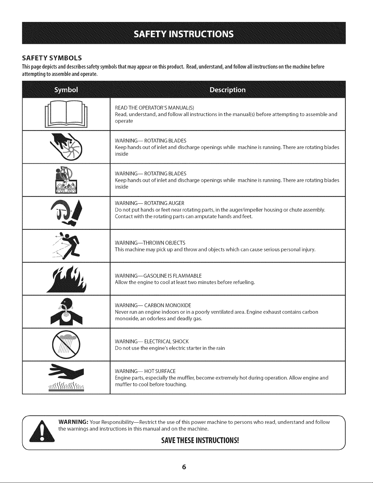
SAFETY SYMBOLS
Thispage depicts and describes safety symbols that may appear on this product. Read, understand, and follow all instructions on the machine before
attempting to assemble and operate.
READ THE OPERATOR'S MANUAL(S)
Read, understand, and follow all instructions in the manual(s) before attempting to assemble and
operate
WARNING-- ROTATING BLADES
Keep hands out of inlet and discharge openings while machine is running. There are rotating blades
inside
WARNING-- ROTATING BLADES
Keep hands out of inlet and discharge openings while machine is running. There are rotating blades
inside
WARNING-- ROTATING AUGER
Do not put hands or feet near rotating parts, in the auger/impeller housing or chute assembly.
Contact with the rotating parts can amputate hands and feet.
WARNING--THROWN OBJECTS
This machine may pick up and throw and objects which can cause serious personal injury.
WARNING--GASOLINE IS FLAMMABLE
Allow the engine to cool at least two minutes before refueling.
WARNING-- CARBON MONOXIDE
Never run an engine indoors or in a poorly ventilated area. Engine exhaust contains carbon
monoxide, an odorless and deadly gas.
WARNING-- ELECTRICAL SHOCK
Do not use the engine's electric starter in the rain
WARNING-- HOT SURFACE
Engine parts, especially the muffler, become extremely hot during operation. Allow engine and
muffler to cool before touching.
WARNING: Your Responsibility--Restrict the use of this power machine to persons who read, understand and follow
the warnings and instructions in this manual and on the machine.
SAVETHESEiNSTRUCTIONS!
6

This page left intentionallyblank.
7
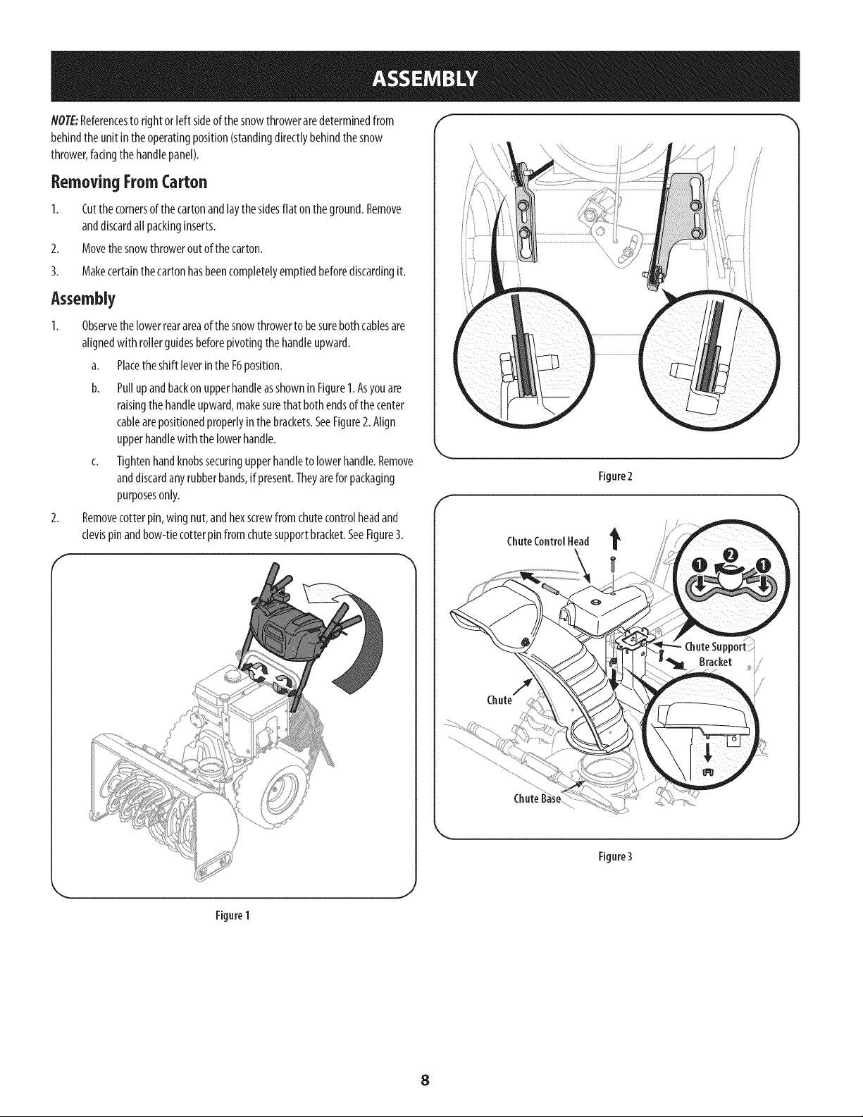
NOTE:Referencesto rightor left sideofthesnowthroweraredeterminedfrom
behindtheunit in theoperatingposition(standingdirectlybehindthesnow
thrower,facingthehandlepanel).
Removing FromCarton
1. Cutthecornersof thecartonandlaythesidesflat ontheground.Remove
anddiscardall packinginserts.
2. Movethe snowthroweroutof thecarton.
3. Makecertainthecartonhasbeencompletelyemptiedbeforediscardingit.
Assembly
1. Observethelowerrearareaof thesnowthrowerto besurebothcablesare
alignedwith rollerguidesbeforepivotingthehandleupward.
a. Placetheshift [everintheF6position.
b. Puffup andbackonupperhandleasshownin Figure1.Asyouare
raisingthe handleupward,makesurethat bothendsof thecenter
cablearepositionedproperlyinthe brackets.SeeFigure2.Align
upperhandlewith thelowerhandle.
c. Tightenhandknobssecuringupperhandleto lowerhandle.Remove
anddiscardanyrubberbands,if present.Theyarefor packaging
purposesonly.
2. Removecotterpin, wingnut,andhexscrewfromchutecontrolheadand
clevispinandbow-tiecotterpinfrom chutesupportbracket.SeeFigure3.
f
Figure2
f
ChuteControl Head
Bracket i,
Chute
-t
Figure3
J
Figure 1
8
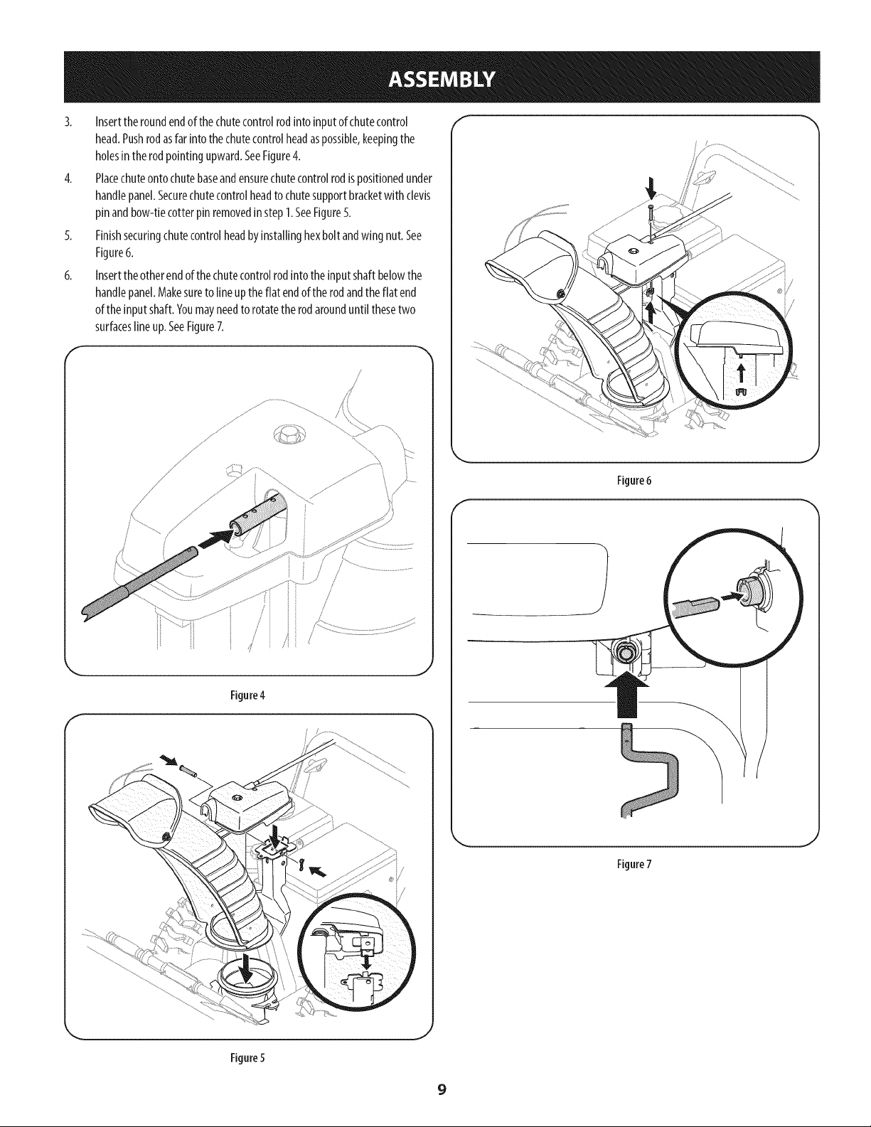
3. Inserttheroundendofthechutecontrolrodinto inputofchutecontrol
head.Pushrodasfar intothe chutecontrolheadaspossible,keepingthe
holesinthe rodpointingupward.SeeFigure4.
4. Placechuteontochutebaseandensurechutecontrolrodispositionedunder
handlepanel.Securechutecontrolheadto chutesupportbracketwithclevis
pinandbow-tiecotterpinremovedinstep1.SeeFigure5.
5. Finishsecuringchutecontrolheadbyinstallinghexbolt andwing nut.See
Figure6.
6. Inserttheotherendof thechutecontrolrodinto theinputshaftbelowthe
handlepanel.Makesureto lineupthe flat endof therodandthe flat end
ofthe inputshaft.Youmayneedto rotatetherodarounduntil thesetwo
surfaceslineup.SeeFigure7.
f
,. J
Figure4
Figure 6
f
Figure7
Figure5
9
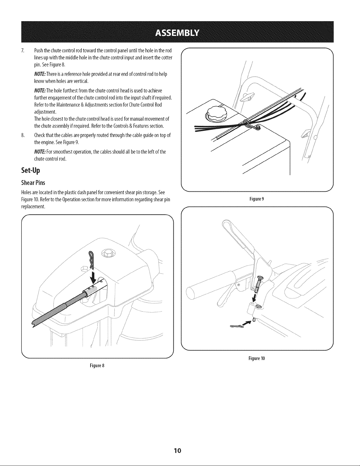
8.
Pushthe chutecontrolrodtowardthecontrolpane[until theholeinthe rod
linesupwith themiddleholeinthechutecontrolinputandinsertthecotter
pin. SeeFigure&
NOTE:Thereisareferenceholeprovidedat rearendof controlrodto help
knowwhenholesarevertical
NOTE:Theholefurthestfrom the chutecontrolheadisusedto achieve
furtherengagementofthechutecontrolrodintotheinputshaftif required.
Referto theMaintenance& AdjustmentssectionforChuteControlRod
adjustment.
Theholeclosestto thechutecontrolheadisusedfor manualmovementof
thechuteassemblyif required.Refertothe Controls& Featuressection.
Checkthat the cablesareproperlyroutedthroughthecableguideontopof
theengine.SeeFigure9.
NOTE:Forsmoothestoperation,the cablesshouldall beto the left ofthe
chutecontrolrod.
Set-Up
ShearPins
Holesarelocatedintheplasticdashpanelforconvenientshearpinstorage.See
Figure10.RefertotheOperationsectionformoreinformationregardingshearpin
replacement.
s_ .......
=/
/
/
Figure8
J
F
s i
//
!
Figure9
Figure10
10
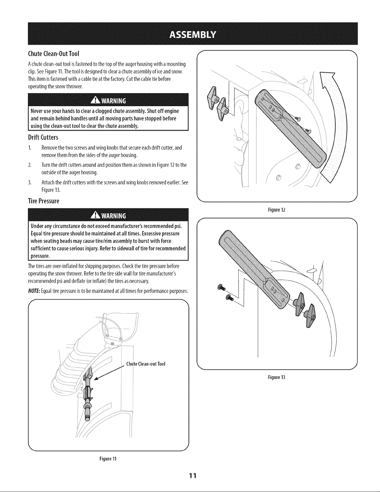
ChuteClean-OutTool f
Achuteclean-outtool isfastenedto thetop oftheaugerhousingwith amounting
clip.SeeFigure11.Thetool isdesignedto cleara chuteassemblyof iceandsnow.
Thisitem isfastenedwith acabletieat thefactory.Cutthe cabletie before
operatingthesnowthrower.
Neveruseyour handsto clearacloggedchute assembly.Shutoff engine
and remainbehind handlesuntil all moving parts havestoppedbefore
usingthe clean-outtool to clearthechute assembly.
Drift Cutters
2.
3.
Removethe two screwsandwingknobsthatsecureeachdrift cutter,and
removethemfromthe sidesof theaugerhousing.
Turnthe drift cuttersaroundandpositionthemasshownin Figure12to the
outsideof the augerhousing.
Attachthedrift cutterswith thescrewsandwingknobsremovedearlier.See
Figure13.
Tire Pressure
Underany circumstancedo notexceedmanufacturer'srecommendedpsi.
Equaltire pressureshouldbe maintainedat all times. Excessivepressure
when seatingbeadsmaycausetirelrim assemblyto burstwith force
sufficient to causeseriousinjury. Referto sidewallof tire for recommended
pressure.
Thetiresareover-inflatedforshippingpurposes.Checkthe tire pressurebefore
operatingthesnowthrower.Referto thetire sidewall fortire manufacturer's
recommendedpsianddeflate(orinflate)thetiresasnecessary.
NOTL::Equaltire pressureisto bemaintainedat alltimesforperformancepurposes.
f
ChuteClean-outTool
//
/
Figure12
J
f
Figure13
Figure11
11
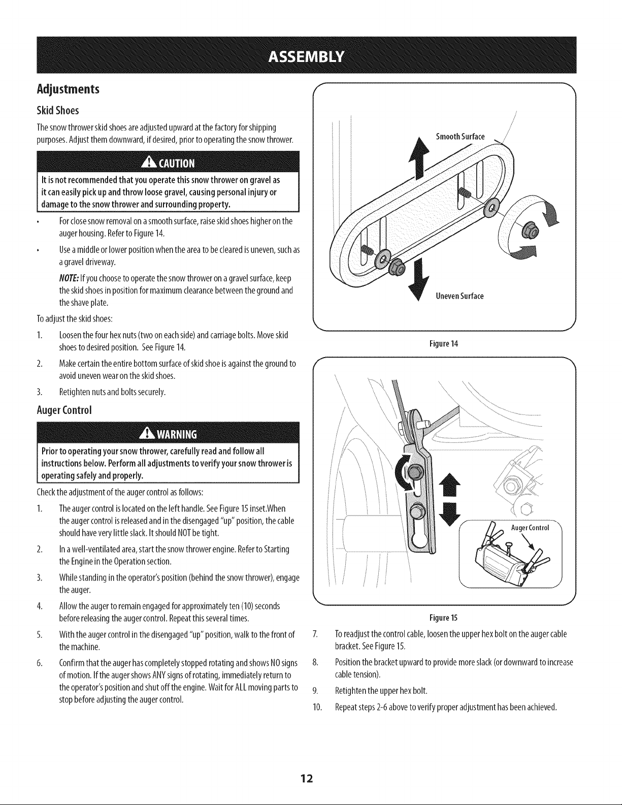
Adjustments f
Skid Shoes
Thesnowthrowerskidshoesareadjustedupwardat thefactoryfor shipping
purposes.Adjustthemdownward,if desired,priorto operatingthesnowthrower.
it isnotrecommendedthat youoperatethis snowthrower on gravelas
it caneasilypickup andthrowloose gravel,causingpersonalinjuryor
damageto thesnowthrowerandsurroundingproperty.
Forclosesnowremovalon asmoothsurface,raiseskidshoeshigheronthe
augerhousing.Referto Figure14.
Useamiddleor lowerpositionwhentheareato beclearedisuneven,suchas
agraveldriveway.
flOTE:Ifyouchooseto operatethesnowthroweron agravelsurface,keep
theskidshoesin positionformaximumclearancebetweenthegroundand
theshaveplate.
Toadjustthe skidshoes:
1. Loosenthe four hexnuts(two oneachside)andcarriagebolts.Moveskid
shoesto desiredposition.SeeFigure14.
2. Makecertaintheentirebottomsurfaceof skidshoeisagainstthe groundto
avoidunevenwearon theskidshoes.
3. Retightennutsandboltssecurely.
AugerControl
Priorto operating yoursnowthrower, carefully readandfollow all
instructionsbelow. Performall adjustmentsto verifyyour snowthrower is
operating safelyand properly.
Checktheadjustmentof theaugercontrolasfollows:
1. Theaugercontrolislocatedon the left handle.SeeFigure15inset.When
theaugercontrolisreleasedandinthedisengaged"up" position,thecable
shouldhaveverylittle slack.ItshouldNOTbetight.
2. Ina well-ventilatedarea,start thesnowthrowerengine.Referto Starting
theEngineinthe Operationsection.
3. Whilestandingintheoperator'sposition(behindthesnowthrower),engage
theauger.
4. Allowtheaugerto remainengagedfor approximatelyten (10)seconds
beforereleasingthe augercontrol.Repeatthisseveraltimes.
5. Withtheaugercontrolin thedisengaged"up" position,walkto thefrontof
themachine.
6.
Confirmthat theaugerhascompletelystoppedrotatingandshowsNOsigns
of motion.Ifthe augershowsANYsignsof rotating,immediatelyreturnto
theoperator'spositionandshutoffthe engine.WaitforALLmovingpartsto
stopbeforeadjustingtheaugercontrol.
f
\
Smooth Surface
UnevenSurface
Figure14
\
Figure15
7. Toreadjustthecontrolcable,loosentheupperhexboltontheaugercable
bracket.SeeFigure15.
8. Positionthebracketupwardtoprovidemoreslack(ordownwardto increase
cabletension).
9. Retightenthe upperhexbolt.
10. Repeatsteps2-6aboveto verify properadjustmenthasbeenachieved.
12
Drive Control
Shift Lever
J
Electric Chute Control (Joystick)
Headlight
Manual
ChuteControl
GasCap _ .\
Chute Assembly \
Drift Cutter
Clean Out
Tool
Auger
Housing
\
/
Augers
Skid Shoe
Auger Control
Wheel Steering Control
Muffler
\
\
Recoil Starter
Oil Fill
Handle
Oil Drain
Figure
Nowthat youhavesetupyoursnowthrower,it's importantto becomeacquainted
with itscontrolsandfeatures.Referto Figure16.
Shift Lever
Theshiftleverislocatedontheright sideofthe handlepanel.Placethe shift
leverintoanyof eightpositionsto controlthe directionoftravelandground
speed.
Forward
Yoursnowthrowerhassixforward(F)speeds.Positionone(1)istheslowest
andpositionsix(6)isthefastest.
Reverse
6
5
4
3
t 2
F1
R1
Yoursnowthrowerhastworeverse(R)speeds.One(1)istheslowerandtwo(2)
isthefaster. [I 2
Drift Cutters
16
Key
Thekeyisasafetydevice.It mustbefully insertedin
orderfor theengineto start. Removethe keywhenthe
snowthrowerisnot in use.
NOTE:Donotturn the ignitionkeyinanattempt tostart
theengine.Doingsomaycauseit to break.
ChokeControl
Thechokecontrolisfoundontherearof theengineandis
activatedbyturningthe rotarychokeknobto theCHOKE
position.Activatingthechokecontrolclosesthechoke
plateonthecarburetorandaidsinstartingtheengine.
ChuteAssembly
J
Snowdrawnintotheaugerhousingisdischargedoutthe chuteassembly.
Thedrift cuttersaredesignedfor useindeepsnow.Theiruseisoptionalfor normal
snowconditions.Maneuverthe snowthrowersothatthecutterspenetratea high
standingsnowdrift to assistsnowfalling into theaugersforthrowing.
Meets ANSiSafetyStandards
CraftsmanSnowThrowersconformtothe safetystandardof theAmericanNationalStandardsInstitute(ANSI).
13
Throttlecontrol
Thethrottle control islocatedon the rear ofthe engine. Itregulates the speed of the
engineand willshut offthe enginewhen moved into the STOPposition.
Depressingthe primerforcesfueldirectlyintothe _J' 444
engine'scarburetorto aidin cold-weatherstarting. 3X
Recoil Starter Handle
Thishandleisusedto manuallystarttheengine.
Electric Starter Button
Pressingthe electricstarterbuttonengagesthe engine'selectricstarterwhen
pluggedinto a 120Vpowersource.
Electric Starter Outlet
Requirestheuseof athree-prongoutdoorextensioncordanda 120Vpowersource/
walloutlet.
OUFill
Engineoil levelcanbe checkedandoil addedthroughtheoil fill.
Headlight
Theheadlightisonwheneverthe engineisrunning.
Auger
Whenengaged,the augerbladesrotateanddrawsnowintothe augerhousing.
WheelSteeringControls
Theleft andfight wheelsteeringcontrolsarelocatedonthe undersideofthe
handles.Squeezethefight controlto turn right; squeezethe left controlto turn left.
flOTE:Operatethe snowthrowerin openareasuntil youarefamiliarwith these
controls.
AugerControl
/ AUGER
CONTROL
Theaugercontrolislocatedon the left handle.Squeezethecontrolgripagainstthe
handleto engagethe augerandstartsnowthrowingaction.Releaseto stop.
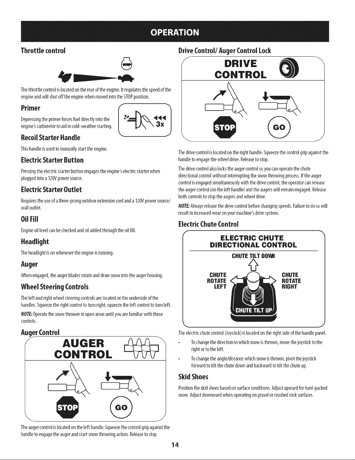
DriveControl/Auger ControlLock
f DRIVE
CONTROL
Thedrivecontrolislocatedon theright handle.Squeezethecontrolgripagainstthe
handleto engagethewheeldrive.Releaseto stop.
Thedrivecontrolalsolockstheaugercontrolsoyoucanoperatethe chute
directionalcontrolwithoutinterruptingthe snowthrowingprocess.Iftheauger
controlisengagedsimultaneouslywith thedrivecontrol,theoperatorcanrelease
theaugercontrol(onthe left handle)andtheaugerswill remainengaged.Release
both controlsto stoptheaugersandwheeldrive.
NOTE:Alwaysreleasethedrivecontrolbeforechangingspeeds.Failureto dosowill
resultinincreasedwearon yourmachine'sdrivesystem.
ElectricChute Control
ELECTRIC CHUTE
DIRECTIONAL CONTROL
CHUTE TILT DOll
CHUTE
ROTATE
LEFT
CHUTE
ROTATE
RIGHT
Theelectricchutecontrol(Joystick)islocatedon therightsideof thehandlepanel.
Tochangethe directionin whichsnowis thrown,movethejoystickto the
rightorto theleft.
Tochangethe angle/distancewhichsnowisthrown,pivot thejoystick
forwardto tilt thechutedownandbackwardto tilt thechuteup.
Skid Shoes
Positionthe skidshoesbasedonsurfaceconditions.Adjustupwardforhard-packed
snow.Adjustdownwardwhenoperatingon gravelor crushedrocksurfaces.
14
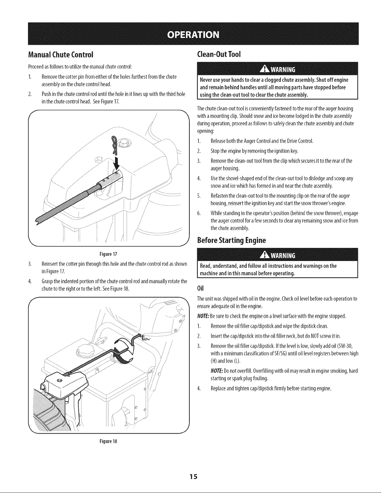
Manual ChuteControl Clean-OutTool
Proceedasfollowsto utilizethe manualchutecontrol:
2.
Removethe cotterpin fromeitherof the holesfurthestfromthechute
assemblyon thechutecontrolhead.
Pushinthechutecontrolroduntil theholein it linesupwith thethird hole
inthechutecontrolhead.SeeFigure17.
,/
/
//
/
Figure17
3. ReJnsertthecotterpinthroughthisholeandthechutecontrolrodasshown
in Figure17.
4. Graspthe indentedportionof thechutecontrolrodandmanuallyrotatethe
chuteto therightor to theleft. SeeFigure18.
J
/ /
/ /
,I i
y i
/
/
Neveruseyour handsto cleara cloggedchuteassembly.Shutoff engine
andremainbehindhandlesuntil all moving parts havestoppedbefore
usingthe clean-outtool to clearthe chuteassembly.
Thechuteclean-outtool isconvenientlyfastenedto the rearof theaugerhousing
with a mountingclip.Shouldsnowandicebecomelodgedinthe chuteassembly
duringoperation,proceedasfollowsto safelycleanthechuteassemblyandchute
opening:
1. ReleaseboththeAugerControlandthe DriveControl.
2. Stoptheenginebyremovingtheignitionkey.
3. Removethe clean-outtoolfromthe clip whichsecuresit to therearof the
augerhousing.
4. Usethe shovel-shapedendof theclean-outtool to dislodgeandscoopany
snowandicewhichhasformedinandnearthechuteassembly.
5. Refastentheclean-outtool to themountingcliponthe rearof the auger
housing,reinserttheignitionkeyandstart thesnowthrower'sengine.
6. Whilestandingintheoperator'sposition(behindthesnowthrower),engage
theaugercontrolforafew secondsto clearanyremainingsnowandicefrom
thechuteassembly.
Before Starting Engine
Read,understand,andfollow all instructionsandwarnings on the
machineand inthis manualbeforeoperating.
Oil
Theunit wasshippedwith oil in theengine.Checkoil levelbeforeeachoperationto
ensureadequateoil intheengine.
NOTE:Besureto checktheengineona levelsurfacewith theenginestopped.
1. Removethe oil filler cap/dipstickandwipethedipstickclean.
2. Insertthecap/dipstickintotheoil filler neck,butdoNOTscrewit in.
3. Removethe oil filler cap/dipstick.If thelevelislow,slowlyaddoil(5W-30,
with a minimumclassificationof SF/SG)until oil levelregistersbetweenhigh
(H)andlow (L).
NOTE:Donot overfill.Overfillingwithoil mayresultin enginesmoking,hard
startingorsparkplugfouling.
4. Replaceandtighten cap/dipstickfirmly beforestarting engine.
Figure 18
15
Gasoline Electrk Starter
Useautomotivegasoline(unleadedorlow leadedto minimizecombustionchamber
deposits)with a minimumof87octane.Gasolinewith up to 10%ethanolor15%
MTBE(MethylTertiaryButylEther)canbeused.Neveruseanoil/gasolinemixture
ordirty gasoline.Avoidgettingdirt, dust,orwaterinthe fuel tank.DONOTuseE85
gasoline.
Refuelin awell-ventilatedareawith theenginestopped.Donotsmokeor
allowflamesor sparksin theareawheretheengineisrefueledor where
gasolineisstored.
Donotoverfillthefuel tank.After refueling,makesurethetank capisclosed
properlyandsecurely.
Becarefulnot to spillfuel whenrefueling.Spilledfuel or fuelvapormay
ignite.Ifanyfuelisspilled,makesuretheareaisdrybeforestartingthe
engine.
Avoidrepeatedorprolongedcontactwith skinorbreathingof vapor.
Useextreme carewhen handlinggasoline.Gasolineisextremely
flammable and thevaporsareexplosive.Neverfuelthe machineindoorsor
while the engineishotorrunning. Extinguishcigarettes,cigars,pipesand
other sourcesof ignition.
I.
2.
Cleanaroundfuel fill beforeremovingcapto fuel.
Afuel levelindicatorislocatedinthe fueltank.SeeFigure16inset.Be
carefulnotto overfill.Filltankuntilfuelreachesthe fuel levelindicatorto
allowspaceforfuel expansion.
Starting TheEngine
Alwayskeephandsandfeet clearof moving parts. Donot usea pressurized
starting fluid. Vaporsareflammable.
flOTEtAllowthe engineto warmup forafew minutesafterstarting.Theenginewill
notdevelopfull poweruntil it reachesoperatingtemperatures.
1. Makecertainboththe augercontrolanddrivecontrolareinthe disengaged
(released)position.
2. Insertkeyintoslot.Makesureit snapsinto place.Donotattemptto turn the
key.
NOTE:Theenginecannotstartwithout thekeyfullyinsertedintothe
ignitionswitch.
Theelectric starter isequippedwith a groundedthree-wire power plug,
andisdesignedto operateon 120voltAChouseholdcurrent.It must be
usedwith a properly groundedthree-prong receptacleat all timesto avoid
the possibilityof electrk shock.Followall instructionscarefully prior to
operatingthe electricstarter. DONOTuseelectric starter in the rain.
Determinethatyourhome'swiring isathree-wiregroundedsystem.Aska licensed
electricianif youarenotcertain.
Ifyouhavea groundedthree-prongreceptacle,proceedasfollows.If youdonot
havethe properhousewiring,DONOTusetheelectricstarterunderanyconditions.
1. Pluganextensioncordinto theoutletlocatedon the engine'ssurface.Plug
theotherendofextensioncordintoathree-prong120-volt,grounded,AC
outlet inawell-ventilatedarea.
Theextensioncordcan beany length, but must beratedfor 15ampsat
125volts,groundedand ratedfor outdoor use.
2. Movethrottlecontrolto FAST(rabbit)_ 11 position.
3. Movechoketo the CHOKE1,'_'1 position(coldenginestart).Ifengineis
warm,placechokeinRUNposition.
4. Pushprimerthree(3)times,makingsureto coverventholein primerbulb
whenpushing.If engineiswarm,pushprimeronlyonce.Alwayscovervent
holewhen pushing.Coolweathermayrequireprimingto berepeated.
5. Pushstarterbuttonto startengine.Oncethe enginestarts,immediately
releasestarterbutton. Electricstarterisequippedwith thermaloverload
protection;systemwill temporarilyshut-downto allowstarterto coolif
electricstarterbecomesoverloaded.
6. Asthe enginewarms,slowlyrotatethe chokecontrolto RUNposition.If the
enginefalters,restartengineandrunwith chokeat half-chokepositionfora
shortperiodoftime,andthenslowlyrotatethechokeinto RUNposition.
7. Afterengineisrunning,disconnectpowercordfrom electricstarter.When
disconnecting,alwaysunplugtheendat the walloutlet beforeunplugging
theoppositeendfromtheengine.
16
RecoilStarter
Donot pullthe starter handlewhile theenginerunning.
1. Movethrottle controlto FAST(rabbit)_J_ position.
2. Movechoketo theCHOKEI,'#1 position(coldenginestart).If engineis
warm,placechokein RUNposition.
3. Pushprimerthree(3)times,makingsureto covervent holewhenpushing.
If engineiswarm,pushprimeronlyonce.Alwayscoverventholewhen
pushing.Coolweathermayrequireprimingto be repeated.
4. Pullgentlyonthe starterhandleuntil itbeginsto resist,then pullquickly
andforcefullyto overcomethecompression.Donotreleasethe handleand
allowitto snapback.ReturnropeSLOWLYto originalposition.If required,
repeatthisstep.
5. Asthe enginewarms,slowlyrotatethechokecontrolto RUNposition.Ifthe
enginefalters,restartengineandrunwith chokeat half-chokepositionfor a
shortperiodof time,andthenslowlyrotatethechokeintoRUNposition.
Toavoid unsupervisedengineoperation, never leavethe machine
unattendedwith theengine running. Turnthe engine off after useand
removekey.
Stopping TheEngine
Afteryouhavefinishedsnow-throwing,runenginefor afewminutesbefore
stoppingto helpdryoffany moistureon the engine.
1. Movethrottle controlto OFFposition.
2. Removethe key.Removingthe keywill reducethepossibilityof
unauthorizedstartingof the enginewhileequipmentisnotinuse.Keepthe
keyina safeplace.Theenginecannotstartwithout thekey.
3. Wipeanymoistureawayfrom thecontrolsonthe engine.
ToEngageDrive
1. Withthethrottle controlinthe Fast(rabbit)_ _111position,moveshift lever
into oneof thesixforward(F)positionsor two reverse(R)positions.Selecta
speedappropriateforthesnowconditionsandapaceyou'recomfortable
with.
NOTE:Whenselectinga DriveSpeed,usetheslowerspeedsuntilyouare
comfortableandfamiliarwith theoperationof thesnowthrower.
2. Squeezethe drivecontrolagainstthehandleandthe snowthrowerwill
move.Releaseit anddrivemotionwill stop.
flOTE:NEVERrepositiontheshift lever(changespeedsordirectionof travel)
without first releasingthedrivecontrolandbringingthesnowthrowerto a
completestop.Doingsowill resultin prematurewearto thesnowthrower'sdrive
system.
ToEngageAuger
Toengagetheaugerandstartthrowingsnow,squeezetheaugercontrol
againstthe left handle.Releaseto stopthe auger.
ReplacingShearPins
Eachaugerbladeissecuredto thespiralshaftwith ashearpinandbow-tieclip.If
anaugerbladestrikesa foreignobjector icejam, thepinwill shearoff to prevent
damageto theblade.Ifan augerbladedoesnotturn, checkto seeif itspinhas
shearedoff. SeeFigure19.
NEVERreplacethe augershear pinswith anything otherthan SearsSKU#
88389/0EMPart No.738-04124Areplacementshearpins.Any damageto
the augergearboxor other componentsasa result of failing to do sowill
NOTbecoveredbyyour snowthrower'swarranty.
Alwaysturn off the snowthrower'sengine and removethe keypriorto
replacingshearpins.
Figure19
17

MAINTENANCESCHEDULE
EachUseandevery5hours
Beforeperforming any type of maintenance/service,disengageall controls
andstop the engine.Wait until all moving parts havecometo a complete
stop. Disconnectsparkplug wire and ground it againstthe engine to
preventunintendedstarting.
Ist 5hours
Annuallyor25hours
Annuallyor50hours
Annuallyor100hours
BeforeStorage
I. Engineoil level
2. Looseor missinghardware
3. Unitandengine.
I. EngineoJl
I. Sparkplug
2. Controllinkagesandpivots
3. Wheels
4. GearshaftandAugershaft
I. EngineoJl
I. Sparkplug
I. Fuelsystem
Followthe maintenanceschedulegivenbelow.Thischartdescribesservice
guidelinesonly.Usethe ServiceLogcolumnto keeptrackofcompleted
maintenancetasks.TolocatethenearestSearsServiceCenteror to scheduleservice,
simplycontactSearsat 1-800-4-MY-HOME®.
1. Check
2. Tightenorreplace
3. Clean
1. Change
1. Check
2. Lubewith light oil
3. Lubewith multipurposeautogrease
4. Lubewith light oil
1. Change
1. Change
1. Runengineuntil it stopsfrom lackof=fuel
GENERALRECOMMENDATIONS
CheckingEngineOil
Beforelubricating, repairing,or inspecting,disengageall controlsandstop
engine.Wait until all movingparts havecometo acompletestop.
NOTE:Checkthe oil levelbeforeeachuseto besurecorrectoillevelismaintained.
Whenaddingoil to theengine,referto viscositychartbelow.Engineoilcapacity
is1100ml(approx.37oz.).Donot over-fill.Usea4-stroke,or anequivalenthigh
detergent,premiumqualitymotoroilcertifiedto meetorexceedU.S.automobile
manufacturer'srequirementsforserviceclassificationSG,SF.Motoroilsclassified
SG,SFwill showthisdesignationon thecontainer.
1. Removethe oil filler cap/dipstkkandwipethe dipstickclean.
2. Insertthecap/dipstkkinto the oil filler neck,butdo NOTscrewit in.
3. Removethe oil filler cap/dipstick.Iflevelis low,slowlyaddoiluntil oil level
registersbetweenhigh(H)andlow (L).SeeFigure20.
4. Replaceandtighten cap/dipstickfirmlybeforestartingengine.
Changing EngineOil
NOTE:Changethe engineoil after thefirst 5 hoursof operationandoncea season
orevery50hoursthereafter.
1. Drainfuel fromtankbyrunningengineuntil thefueltank isempty.Besure
fuelfill capissecure.
2. Placesuitableoil collectioncontainerunderoil drainplug.
3. Removeoil drainplug.SeeFigure21onnext page.
Figure20
Tipunitto drainoil intothecontainer.Usedoil mustbedisposedof at a
propercollectioncenter.
J
Usedoii isa hazardouswaste product.Disposeof usedoil properly.Donot
discardwith householdwaste. Checkwithyour localauthorities or Sears
ServiceCenterfor safedisposal/recyclingfacilities.
5. Reinstallthedrainplugandtighten it securely.
18
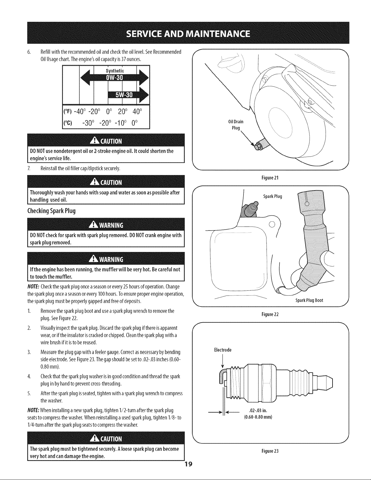
Refillwith therecommendedoil andcheckthe oil level.SeeRecommended
OilUsagechart.Theengine'soil capacityis37ounces.
(oF)-40o-20 o 0o 200 400
(oc) -30° -20° -10 ° 0°
DONOTuse nondetergentoil or 2-strokeengine oil. It couldshorten the
engine'sservicelife.
7. Reinstalltheoil filler cap/dipsticksecurely.
Thoroughlywashyourhandswith soapandwater assoonaspossibleafter
handling usedoil.
CheckingSparkPlug
DONOTcheckfor sparkwith sparkplug removed.DONOTcrankenginewith
sparkplug removed.
Ifthe engine hasbeenrunning,the muffler will bevery hot. Becarefulnot
to touchthe muffler.
NOTE:Checkthe sparkplugonceaseasonor every25 hoursof operation.Change
thesparkplugonceaseasonorevery100hours.Toensureproperengineoperation,
thesparkplugmustbeproperlygappedandfreeof deposits.
1. Removethe sparkplugbootandusea sparkplugwrenchto removethe
plug.SeeFigure22.
2. Visuallyinspectthesparkplug.Discardthe sparkplugif thereisapparent
wear,or if theinsulatoriscrackedorchipped.Cleanthesparkplugwith a
wirebrushifit isto be reused.
3.
Measurethepluggapwith afeelergauge.Correctasnecessarybybending
sideelectrode.SeeFigure23.Thegapshouldbesetto .02-.03inches(0.60-
0.80mm).
4. Checkthatthe sparkplug washerisin goodconditionandthreadthespark
pluginbyhandto preventcross-threading.
5. Afterthesparkplugisseated,tightenwith asparkplugwrenchto compress
thewasher.
NOTE:Wheninstallinganewsparkplug,tighten 1/2-turnafterthe sparkplug
seatsto compressthe washer.Whenreinstallinga usedsparkplug,tighten1/8- to
1/4-turnafterthe sparkplugseatsto compressthewasher.
Oil Drain
Plug \
Figure21
SparkPlug
SparkPlugBoot
Figure22
Electrode
Thesparkplug mustbe tightened securely.Aloosesparkplugcan become
very hotandcan damagethe engine.
19
Figure23
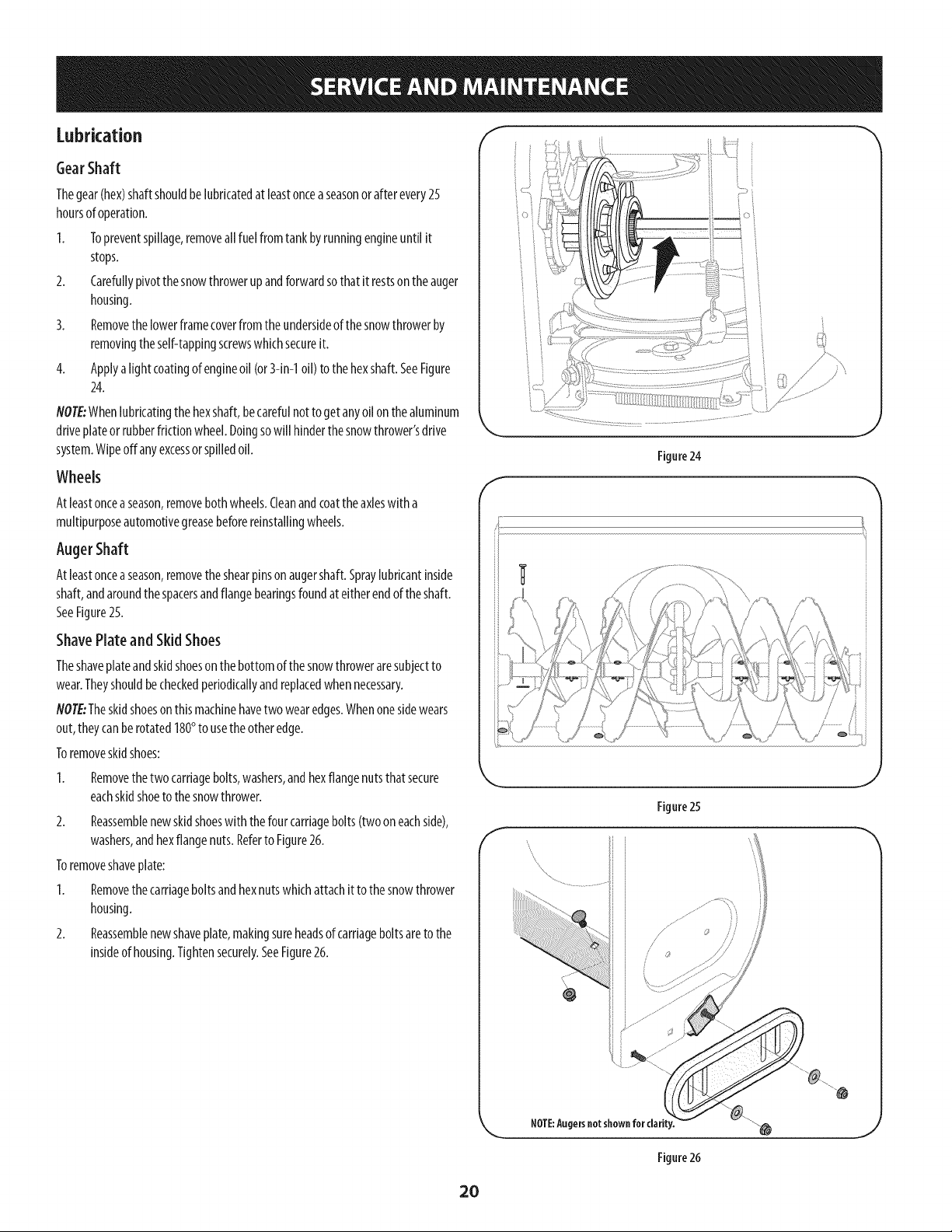
Lubrication "I
GearShaft
Thegear(hex)shaftshouldbelubricatedat leastonceaseasonor after every25
hoursof operation.
I. Topreventspillage,removeall fuel fromtankbyrunningengineuntil it
stops.
2. Carefullypivotthe snowthrowerupandforwardsothat it restsontheauger
housing.
3. Removethe lowerframecoverfrom the undersideof thesnowthrowerby
removingtheself-tappingscrewswhichsecureit.
4. Applya lightcoatingof engineoil (or3-in-1oil) to the hexshaft.SeeFigure
24.
NOTE:Whenlubricatingthe hexshaft,becarefulnot to getanyoil onthe aluminum
driveplateorrubberfrictionwheel.Doingsowill hinderthesnowthrower'sdrive
system.Wipeoffany excessor spilledoil.
Wheels
Atleastonceaseason,removebothwheels.Cleanandcoattheaxleswitha
multipurposeautomotivegreasebeforereinstallingwheels.
AugerShaft
Atleastonceaseason,removetheshearpinson augershaft.Spraylubricantinside
shaft,andaroundthespacersandflangebearingsfoundat eitherendof theshaft.
SeeFigure25.
ShavePlate and Skid Shoes
Theshaveplateandskidshoeson the bottomofthesnowthroweraresubjectto
wear.Theyshouldbecheckedperiodkallyandreplacedwhennecessary.
NOTE:Theskidshoeson thismachinehavetwo wearedges.Whenonesidewears
out,theycanberotated180° to usethe otheredge.
Toremoveskidshoes:
Removethetwocarriagebolts,washers,andhexflangenutsthatsecure
eachskidshoetothesnowthrower.
2. Reassemblenewskidshoeswith thefourcarriagebolts(twoon eachside),
washers,andhexflangenuts.Referto Figure26.
Toremoveshaveplate:
1. Removethe carriageboltsandhexnutswhichattachitto thesnowthrower
housing.
2. Reassemblenewshaveplate,makingsureheadsof carriageboltsareto the
insideof housing.Tightensecurely.SeeFigure26.
f
Figure24
J
f
NOTE:Augersnot shown for clarity.
Figure26
20
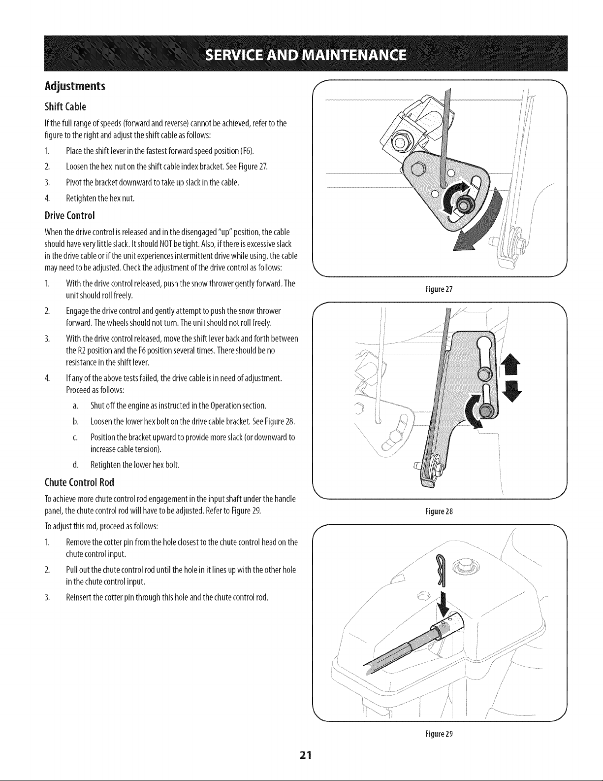
Adjustments
Shift Cable
If thefull rangeof speeds(forwardandreverse)cannotbeachieved,referto the
figureto thefight andadjusttheshift cableasfollows:
I. Placetheshift leverinthe fastestforwardspeedposition(F6).
2. Loosenthe hex nut ontheshift cableindexbracket.SeeFigure27.
3. Pivotthe bracketdownwardtotakeupslackin the cable.
4. Retightenthe hexnut.
DriveControl
Whenthedrivecontrolis releasedandinthe disengaged"up" position,thecable
shouldhaveverylittle slack.ItshouldNOTbetight. Also,if thereisexcessiveslack
inthedrivecableor ifthe unit experiencesintermittentdrivewhileusing,thecable
mayneedto beadjusted.Checkthe adjustmentof thedrivecontrolasfollows:
I. With thedrivecontrolreleased,pushthesnowthrowergentlyforward.The
unit shouldroll freely.
2. Engagethedrivecontrolandgentlyattemptto pushthe snowthrower
forward.Thewheelsshouldnot turn. Theunit shouldnot roll freely.
3. Withthedrivecontrolreleased,movetheshift leverbackandforthbetween
theR2positionandthe F6positionseveraltimes.Thereshouldbeno
resistancein theshift lever.
4. If anyof theabovetestsfailed,thedrivecableisinneedof adjustment.
Proceedasfollows:
a. Shutoff the engineasinstructedinthe Operationsection.
b. Loosenthe lowerhexbolt onthe drivecablebracket.SeeFigure28.
c. Positionthebracketupwardto providemoreslack(ordownwardto
increasecabletension).
d. Retightenthe lowerhexbolt.
ChuteControlRod
Toachievemorechutecontrolrodengagementintheinputshaftunderthe handle
panel,the chutecontrolrodwill haveto beadjusted.Referto Figure29.
Toadjustthisrod,proceedasfollows:
I. Removethe cotterpin fromtheholeclosestto thechutecontrolheadon the
chutecontrolinput.
2. Pullout thechutecontrolroduntilthe holeinit linesupwith theotherhole
inthechutecontrolinput.
3. Reinsertthe cotterpinthroughthisholeandthe chutecontrolrod.
f
Figure27
Figure28
Figure29
21
AugerControl
Referto theAssemblysectionforinstructionson adjustingtheaugercontrolcable.
Skid Shoes
Referto theAssemblysectionforinstructionson adjustingtheskidshoes.
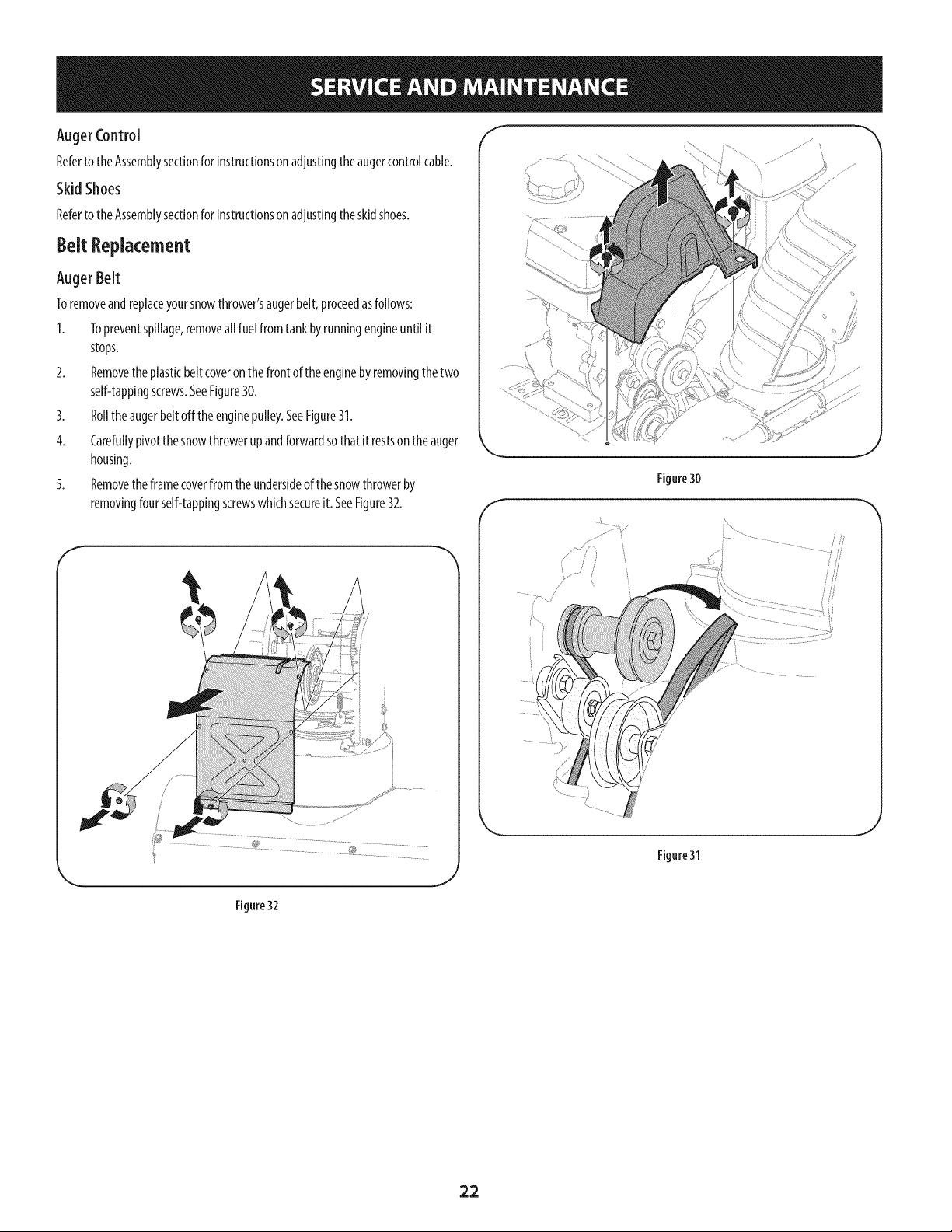
Belt Replacement
Auger Belt
Toremoveandreplaceyoursnowthrower'saugerbelt,proceedasfollows:
I. Topreventspillage,removeall fuel fromtankbyrunningengineuntil it
stops.
2. Removethe plasticbelt coveronthefront of theenginebyremovingthetwo
self-tappingscrews.SeeFigure30.
3. Rollthe augerbeltoffthe enginepulley.SeeFigure31.
4. Carefullypivotthe snowthrowerupandforwardsothat it restsontheauger
housing.
5. Removethe framecoverfromthe undersideof thesnowthrowerby
removingfourself-tappingscrewswhichsecureit. SeeFigure32.
f
Figure 30
J
f
......................................../
................; /
Figure31
Figure 32
22
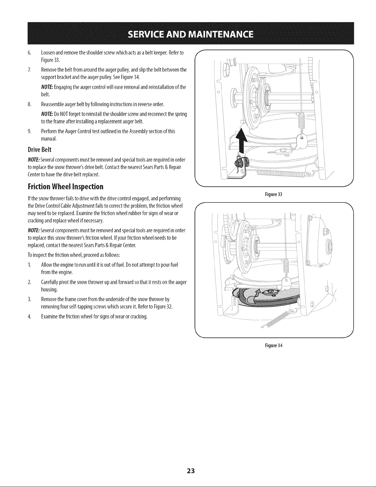
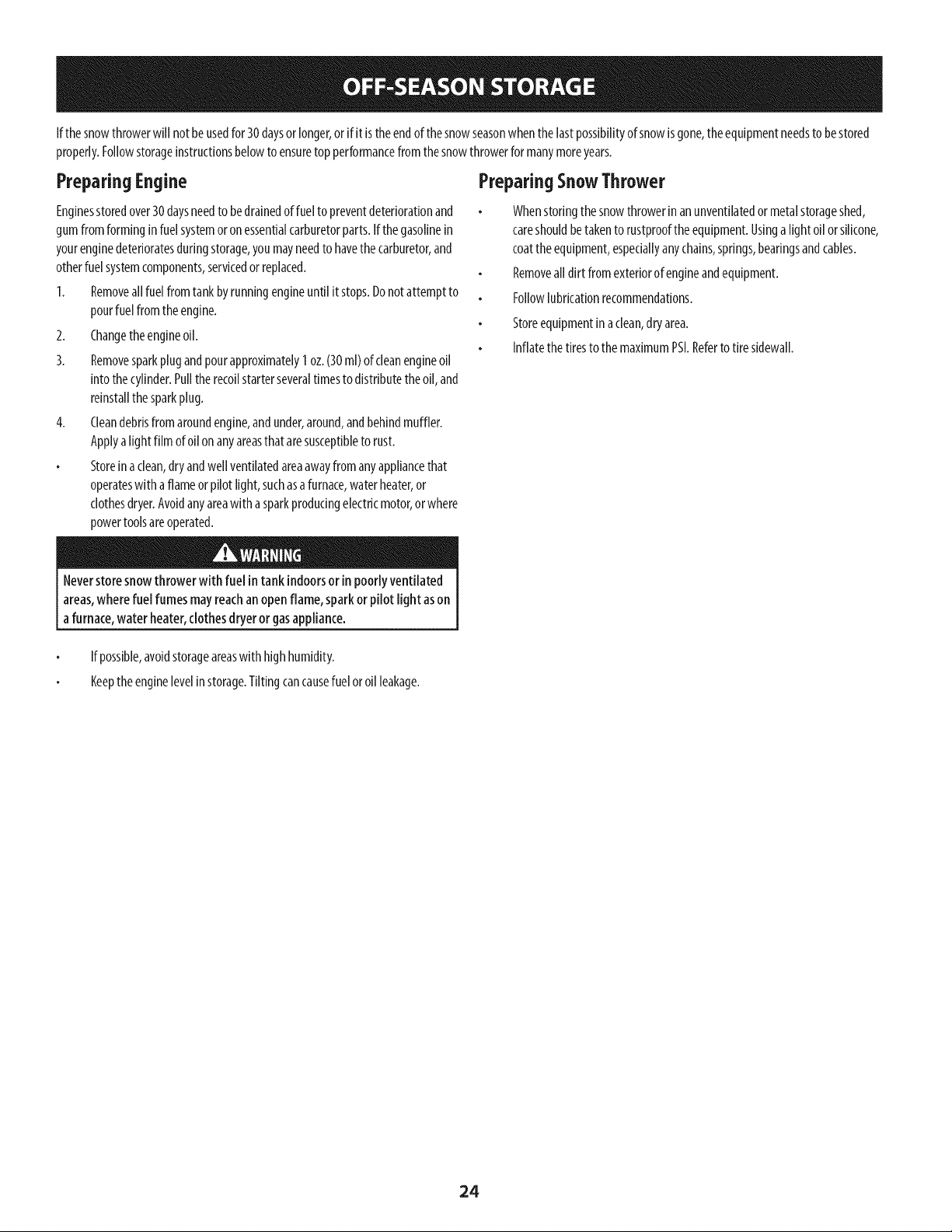
8.
Loosenandremovetheshoulderscrewwhichactsasabelt keeper.Referto
Figure33.
Removethe belt fromaroundtheaugerpulley,andslipthe belt betweenthe
supportbracketandtheaugerpulley.SeeFigure34.
NOTE:Engagingthe augercontrolwill easeremovalandreinstallationof the
belt.
Reassembleaugerbeltbyfollowinginstructionsinreverseorder.
flOTE:DoNOTforgetto reinstalltheshoulderscrewandreconnectthespring
to theframeafterinstallingareplacementaugerbelt.
Performthe AugerControltestoutlinedintheAssemblysectionof this
manual.
Drive Belt
flOTE:Severalcomponentsmustberemovedandspecialtoolsarerequiredin order
to replacethesnowthrower'sdrivebelt.ContactthenearestSearsParts& Repair
Centerto havethe drivebelt replaced.
FrictionWheel inspection
If thesnowthrowerfailsto drivewith thedrivecontrolengaged,andperforming
theDriveControlCableAdjustmentfailsto correctthe problem,thefrictionwheel
mayneedto bereplaced.Examinethefrictionwheelrubberforsignsof wearor
crackingandreplacewheelif necessary.
flOTE:Severalcomponentsmustberemovedandspecialtoolsarerequiredin order
to replacethissnowthrower'sfrictionwheel.Ifyourfrictionwheelneedsto be
replaced,contactthe nearestSearsParts& RepairCenter.
Toinspectthefrictionwheel,proceedasfollows:
1. Allowtheengineto rununtil it isoutof fuel.Donotattemptto pourfuel
fromtheengine.
2. Carefullypivotthe snowthrowerupandforwardsothat it restson theauger
housing.
3. Removethe framecoverfromthe undersideof thesnowthrowerby
removingfourself-tappingscrewswhichsecureit. Referto Figure32.
4. Examinethe frictionwheelforsignsof wearor cracking.
Figure33
i •
:_ /
Figure34
23
If thesnowthrowerwill notbeusedfor 30daysor longer,orif it is theendof thesnowseasonwhenthelastpossibilityof snowisgone,the equipmentneedsto bestored
properly.Followstorageinstructionsbelowto ensuretop performancefrom thesnowthrowerformanymoreyears.
PreparingEngine
Enginesstoredover30daysneedto bedrainedof fuel to preventdeteriorationand
gumfromforminginfuel systemor on essentialcarburetorparts.If thegasolinein
yourenginedeterioratesduringstorage,youmayneedto havethe carburetor,and
otherfuelsystemcomponents,servicedorreplaced.
1. Removeall fuel fromtankbyrunningengineuntil it stops.Donotattemptto
pourfuelfrom theengine.
2. Changetheengineoil.
3. Removesparkplugandpourapproximately1oz.(30ml)ofcleanengineoil
into thecylinder.Pulltherecoilstarterseveraltimesto distributetheoil, and
reinstallthe sparkplug.
4. Cleandebrisfromaroundengine,andunder,around,andbehindmuffler.
Applya lightfilm ofoil on anyareasthat aresusceptibleto rust.
Storeinaclean,dryandwell ventilatedareaawayfromanyappliancethat
operateswith aflameorpilot light,suchasa furnace,waterheater,or
clothesdryer.Avoidanyareawitha sparkproducingelectricmotor,orwhere
powertoolsareoperated.
PreparingSnowThrower
Whenstoringthe snowthrowerin anunventilatedormetalstorageshed,
careshouldbetakento rustproofthe equipment.Usinga lightoil orsilicone,
coattheequipment,especiallyanychains,springs,bearingsandcables.
Removeall dirt fromexteriorof engineandequipment.
Followlubricationrecommendations.
Storeequipmentinaclean,dryarea.
Inflatethe tiresto themaximumPSI.Referto tire sidewall.
Neverstore snowthrower with fuel intank indoorsor in poorlyventilated
areas,wherefuel fumes mayreachan openflame, sparkor pilotlight ason
a furnace,water heater,clothesdryeror gasappliance.
If possible,avoidstorageareaswith highhumidity.
Keeptheenginelevelin storage.Tiltingcancausefuelor oil leakage.
24

25
Disconnectthe sparkplug wireandgroundit againstthe engineto prevent
unintendedstarting. Beforeperforminganytypeof maintenance/service,
disengageall controls andstopthe engine.Wait until aHmovingparts
havecometo a completestop.Alwayswear safetyglassesduringoperation
or while performingany adjustmentsor repairs.
Thissectionaddressesminorserviceissues.Tolocatethe nearestSearsServiceCenterorto scheduleservice,simplycontactSearsat 1-800-4-MY=HOMP.
Engine fails to start 1.
2.
3.
4.
5.
6.
7.
Choke control not in CHOKE position.
Spark plug wire disconnected.
Faulty spark plug.
Fuel tank empty or stale fuel.
Engine not primed.
Key not inserted.
Extension cord not connected (when
1. Move choke control to CHOKE position.
2. Connectwire to spark plug.
3. Clean, adjust gap, or replace.
4. Fill tank with clean, fresh gasoline.
5. Prime engine as instructed in the Operation Section.
6. Insert key fully into the switch.
7. Connect one end of the extension cord to the
Engine running erratically/
inconsistent RPM (hunting
or surging)
Excessive vibration
Lossof power
Unit fails to propel itself
using electric start button, on models so
equipped).
1. Engine running on CHOKE.
2. Stale fuel.
3. Water or dirt in fuel system.
4. Carburetor out of adjustment.
5. Over-governed engine.
1. Loose parts or damaged auger.
1. Spark plug wire loose.
2. Gas cap vent hole plugged.
1. Drive cable in need of adjustment.
2. Drive belt loose or damaged.
3. Worn friction wheel.
electric starter outlet and the other end to a three-
prong 120-volt, grounded, ACoutlet.
1. Move choke control to RUN position.
2. Fill tank with clean, fresh gasoline.
3. Drain fuel tank by running engine until it stops. Refill
with fresh fuel.
4.
5.
1.
1.
2.
1.
2.
3.
Contact your Sears Parts & Repair Center.
Contact your Sears Parts & Repair Center.
Stop engine immediately and disconnect spark
plug wire. Tighten all bolts and nuts. If vibration
continues, have unit serviced by a Sears Parts &
Repair Center.
Connect and tighten spark plug wire.
Remove ice and snow from gas cap. Be certain vent
hole is clear.
Adjust drive control cable. Refer to Service and
Maintenance section.
Have drive belt replaced. Contact your Sears Parts &
Repair Center.
Have friction wheel replaced at a Sears Parts &
Repair Center.
NEED MORE HELP?
Find this and a[[ your other product manuals online,
Get answers from our team of home experts.
Get a personalized maintenance plan for your home.
Find information and tools to help Mth home projects.
26
Unit fails to discharge snow
Chute fails to easily rotate
180 degrees
1. Chute assembly clogged. 1. Stop engine immediately and disconnect spark
2. Foreign object lodged in auger.
3. Auger cable in need of adjustment.
4. Auger belt loose or damaged.
5. Shearpin(s) sheared.
1. Chute assembled incorrectly.
plug wire. Clean chute assembly and inside of auger
housing with clean-out tool or a stick.
2. Stop engine immediately and disconnect spark plug
wire. Remove object from auger with clean-out tool
or a stick.
3. Adjust auger control cable. Refer to Assembly
section.
4. Replace auger belt. Refer to Service and
Maintenance section.
5. Replace with new shear pin(s).
1. Disassemble chute control and reassemble as
directed in the Assembly section.
NEED MORE HELP?
YotJU,fir_} the _: swe a_] :m,_"Yeo_:__._a_,a_emy[f_eo_@_,,,,,,,fo_' free!
o Find this and a[[ your other product manuals online.
Get answers from our team of home experts,
o Get a personalized maintenance plan for your home_
Find information and tools to help with home projects.
27
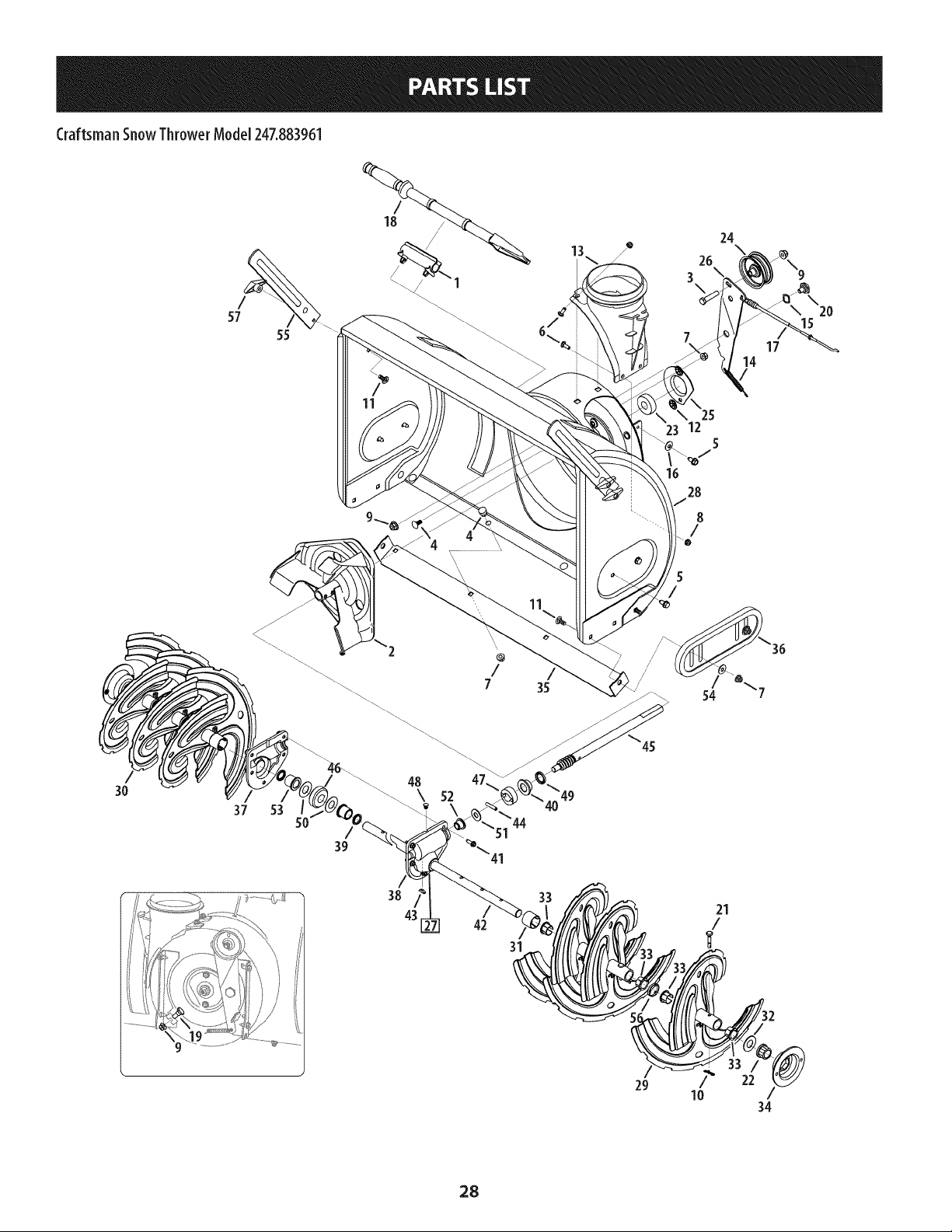
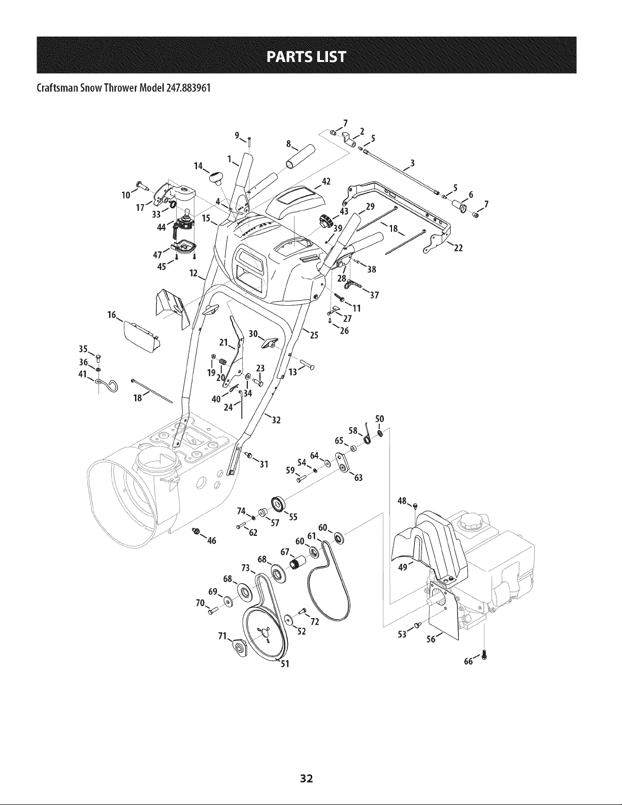
Craftsman SnowThrower Model 247.883961
/
18
24
13
26
/ 3
/ 1 % j&
/ o
L\
20
57 15
55
35
\
25
23 12
5
7
16
28
8
/
5
/
/
/
54
/
7
14
17
3O
37 53
42
31
21
/
29
10 /
34
28
CraftsmanSnowThrowerModel 247.883961
m
!
1.
2.
3.
4.
5.
6.
7.
8.
9.
10.
11.
12.
13.
14.
15.
16.
17.
18.
19.
20.
21.
22.
23.
24.
25.
26.
27.
28.
29.
731-2635
684-04057A-0637
710-0347
710-0451
710-04484
710-0703
712-04063
712-04064
712-04065
714-04040
710-0276
926-04012
731-07525
732-04460
736-0174
736-0242
946-04230A
931-2643
738-0143
938-0281
738-04124A
941-0245
941-0309
756-04224
790-00075
790-00080A-0637
918-04165A
684-04267-0691
684-04107-4044
Snow Removal Tool Mount
Impeller Assembly, 12" Dia.
Hex Screw, 3/8-16, 1.75, Gr5
Bolt, Carriage, 5/16-18, .750 Grl
Screw, 5/16-18, 0.750
Screw, Carriage, 1/4-20, .750, GrS
Nut, Flange Lock, 5/16-18, Nylon
Nut, Flange Lock, 1/4-20, Nylon
Nut, Flange Lock, 3/8-16, Nylon
Cotter Pin, Bow-tie
Scr., Crg., 5/16-18 x 1.00
Nut, Push-on, .25 Dia
Chute, Adapter 5" Dia
Spring, Extension, .38 OD x 4.59
Washer, Wave, .625 x .885 x .015
Washer, Bell, .340 x .872 x .060
Clutch Cable, Auger, 47.23"
Snow Removal Tool
Screw, Shoulder, .498 x .34, 3/8-16
Screw, Shoulder, .625 x .17, 3/8-16
Shear Pin, .25 x 1.50
Bearing, Hex Flange x .75 ID
Bearing, Ball, .75 ID x 1.85 OD
Flat Pulley, Idler, 2.75 OD
Housing, Bearing, 1.85 ID
Bracket, Auger Idler w/Brake
Gearbox Assembly, Auger, 30"
Housing Assembly, Auger 30"
Spiral Assembly, LH
m
m
30.
31.
32.
33.
34.
35.
36.
37.
38.
39.
40.
41.
42.
43.
44.
45.
46.
47.
48.
49.
50.
51.
52.
53.
54.
55.
56.
57.
684-04108-4044
731-04870
736-0188
741-0493A
790-00087A-0637
790-00119-0691
731-05984A
Spiral Assembly, RH
Spacer, 1.25 OD x .75 ID x 1.00
Washer, Flat, .76 x 1.49 x .06
Bushing, Flange, .80 ID x .91 OD
Housing, 1" Hex Bearing
Shave Plate, 2.25 x 29.66
Slide Shoe
918-0123A
918-0124A
921-0338
741-0662
710-0642
711-04282
914-0161
715-04021
917-04126
917-0528A
718-04071
721-0325
721-0327
936-0351
736-3084
741-0663
741 -0661 B
936-0159
790-00181-0637
731-04871
920-0284
Housing, Auger, RH Reduced
Housing, Auger, LH Reduced
Seal, Oil, .750 x 1.00 x .125
Bearing, Flange, .75 x 1.0 x .59
Screw, Self-tapping, 1/4-20, 0.750
Axle, Auger, 30"
Key, Hi-pro 3/16 x 5/8
Pin, Dowel, .25 OD x 1.2
Shaft, Worm .75 OD
Gear, Worm 20T
Collar, Thrust
Plug, 1/4 x .437
Seal, Oil, .75 x 1 x .131
Washer, Flat, .760 ID x 1.50D
Washer, Flat, .51 x 1.12
Bearing, Flange, .75 x 1.0 x .925
Bearing, Flange, .75 x 1.00 x .975
Washer, Flat, .349 x .879 x .063
Drift Cutter
Spacer, 1.25 OD x .75 ID x 3/16
Wing Nut
29
Craftsman SnowThrower Model 247.883961
42
45
2
I
10
20
14
13
21
22
2O
12
13
14
26 45 24
61/
36
I
28
3O
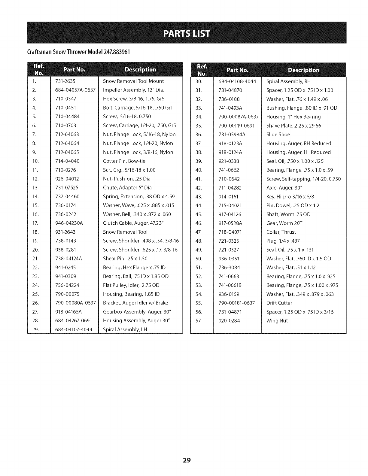
Craftsman SnowThrowerModel 247.883961
m
1.
2.
3.
4.
5.
6.
7.
8.
9.
10.
11.
12.
13.
14.
15.
16.
17.
18.
19.
20.
21.
22.
23.
24.
25.
26.
27.
28.
29.
30.
31.
735-04099
711-1268B
946-05067
732-04345
790-00207C
684-04156A
750-04474
914-0126
735-04100
917-04210
941-0245
790-00206A-0637
756-0625
738-0924A
618-06988
618-06987
936-3015
732-04311A
731-05297
916- 0104
736-0188
750-06087
941-0563
938-04180
731-04873
710-0788
790-00527-0691
634-04136-0911
634-04137-0911
710-05339
684-04154B-0637
790-00096A-0637
748-0190
Plug, 3/8 ID
Actuator Shaft
Drive Clutch Cable
Extension Spring
Drive Clutch Cable Guide Bracket
Shift Rod Assembly
Axle Support Tube
Hi Pro Key
Plug, 1/2 ID
Gear, 56T
Hex Flange Bearing
Auger Clutch Cable Guide Bracket
Cable Roller
C Screw, 1/4-28 x 0.375
Dogg Assembly - LH
Dogg Assembly - RH
Washer, Flat
Torsion Spring, .750 ID x .968 Lg.
Spacer
E Ring
Flat Washer, .76 x 1.49 x .06
Spacer
Ball Bearing
Axle
Spacer
TT Screw, 1/4-20 x 1.0
Shaft Retainer- LH
Wheel Complete - LH
Wheel Complete - RH
Screw, 5/16-24 x 0.75
Friction Wheel Support Brkt. Assy.
Auger Cable Guide Bracket
Spacer
N
32.
33.
34.
35.
36.
37.
38.
39.
40.
41.
42.
43.
44.
45.
46.
47.
48.
49.
50.
51.
52.
53.
54.
55.
56.
57.
58.
59.
60.
61.
62.
63.
738-04184A
790-00316-0691
656-04055
918-06072
684-04153C
716-0136
726-0221
790-00183C-0691
932-0264
712-0417A
946-0956C
790-00528-0691
750-0767
712-04065
710-0751
790-00217A-0637
790-00218A-0637
712-04063
712-04064
618-0063A
935-04054
790-00174C
710-04484
710-1652
918-06054
918-06056
711-06117
916-0231
717-05146
717-1209A
736-04581
736-05031
Shoulder Screw
Frame Cover
Friction Wheel Disc Assembly
Drive Shaft Assembly
Friction Wheel Assembly
Retainer Ring
Speed Nut
Wheel Drive Frame
Extension Spring
Flange Nut, 5/8-18
Steering Cable
Shaft Retainer- RH
Axle Spacer
Flange Lock Nut, 3/8-16
Hex Screw, 1/4-20 x .620
Speed Selector Pivot Bracket
Speed Selector Shift Bracket
Flange Lock Nut, 5/16-18
Flange Lock Nut, 1/4-20
Friction Wheel Bearing Assembly
Friction Wheel
Friction Plate
Screw, 5/16-18 x .750
AB Screw, 1/4-20 x 0.625
Gear Assembly, Plantry Ring
Carrier Assembly, Plantry Ring
Shaft, Strbl Drv Hex, .812
E-Ring
Gear, Sun, 18T
Gear, 12T
Washer, Thrust, .75 x 1.25 x .03
Washer, Flat, .67 x 1.174 x .02
31
Craftsman SnowThrower Model247.883961
42
29
7
J
_\38
66/g
32
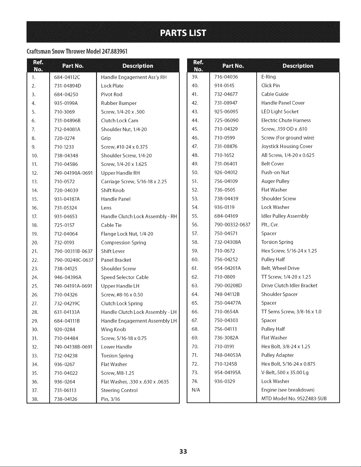
Craftsman SnowThrower Model 247.883961
M
I.
2.
3.
4.
5.
6.
7.
8.
9.
10.
11.
12.
13.
14.
15.
16.
17.
18.
19.
20.
21.
22.
23.
24.
25.
26.
27.
28.
29.
30.
31.
32.
33.
34.
35.
36.
37.
38.
684-04112C
731-04894D
684-04250
935-0199A
710-3069
731-04896B
712-04081A
720-0274
710-1233
738-04348
710-04586
749-04190A-0691
710-0572
720-04039
931-04187A
731-05324
931-04653
725-0157
712-04064
732-0193
790-00311B-0637
790-00248C-0637
738-04125
946-04396A
749-04191A-0691
710-04326
732-04219C
631-04133A
684- 04111 B
920-0284
710-04484
749-04138B-0691
732-04238
936-0267
710-04022
936-0264
731-06113
738-04126
Handle Engagement Ass'y RH
Lock Plate
Pivot Rod
Rubber Bumper
Screw, 1/4-20 x .500
Clutch Lock Cam
Shoulder Nut, 1/4-20
Grip
Screw, #10-24 x 0.375
Shoulder Screw, 1/4-20
Screw, 1/4-20 x 1.625
Upper Handle RH
Carriage Screw, 5/16-18 x 2.25
Shift Knob
Handle Panel
Lens
Handle Clutch Lock Assembly- RH
Ca ble Tie
Flange Lock Nut, 1/4-20
Compression Spring
Shift Lever
Panel Bracket
Shoulder Screw
Speed Selector Cable
Upper Handle LH
Screw, #8-16 x 0.50
Clutch Lock Spring
Handle Clutch Lock Assembly - LH
Handle Engagement Assembly LH
Wing Knob
Screw, 5/16-18 x 0.75
Lower Handle
Torsion Spring
Flat Washer
Screw, M8-1.25
Flat Washer, .330 x .630 x .0635
Steering Control
Pin, 3/16
N
39.
40.
41.
42.
43.
44.
45.
46.
47.
48.
49.
50.
51.
52.
53.
54.
55.
56.
57.
58.
59.
60.
61.
62.
63.
64.
65.
66.
67.
68.
69.
70.
71.
72.
73.
74.
N/A
716-04036
914-0145
732-04677
731-08947
925-06095
725-06090
710-04329
710-0599
731-08876
710-1652
731-06401
926-04012
756- 04109
736-0505
738-04439
936-0119
684-04169
790-00332-0637
750-04571
732-04308A
710-0672
756-04252
954-04201A
710-0809
790-00208D
748-04112B
750-04477A
710-0654A
750-04303
756- 04113
736-3082A
710-0191
748-04053A
710-1245B
954- 04195A
936-0329
E-Ring
Click Pin
Cable Guide
Handle Panel Cover
LED Light Socket
Electric Chute Harness
Screw, .159 OD x .610
Screw (For ground wire)
Joystick Housing Cover
AB Screw, 1/4-20 x 0.625
Belt Cover
Push-on Nut
Auger Pulley
Flat Washer
Shoulder Screw
Lock Washer
Idler Pulley Assembly
Pit., Cvr.
Spacer
Torsion Spring
Hex Screw, 5/16-24 x 1.25
Pulley Half
Belt, Wheel Drive
TT Screw, 1/4-20 x 1.25
Drive Clutch Idler Bracket
Shoulder Spacer
Spacer
TT Seres Screw, 3/8-16 x 1.0
Spacer
Pulley Half
Flat Washer
Hex Bolt, 3/8-24 x 1.25
Pulley Adapter
Hex Bolt, 5/16-24 x 0.875
V-Belt,.500 x 35.00 Lg
Lock Washer
Engine (see breakdown)
MTD Model No. 952Z483-SUB
33
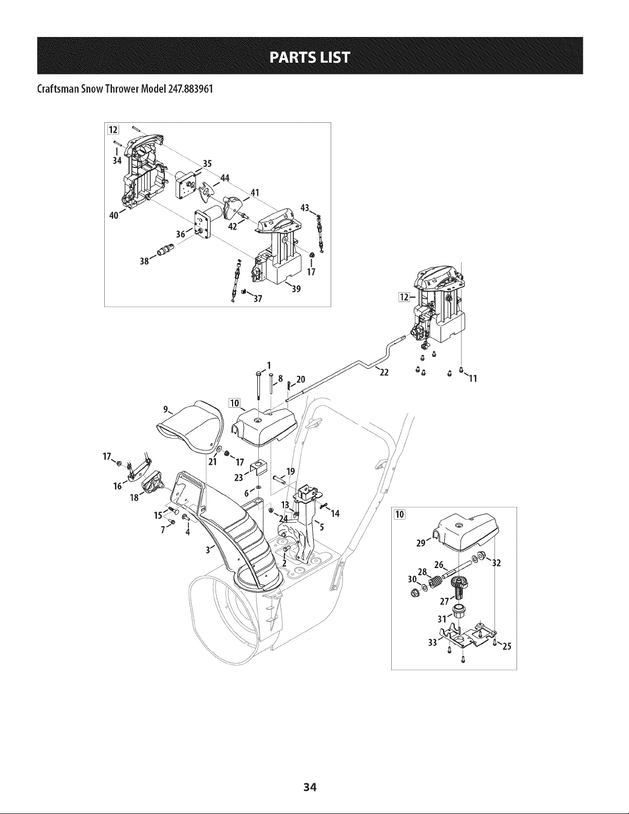
Craftsman SnowThrower Model 247.883961
21
231
'25
34
Craftsman SnowThrowerModel 247.883961
1.
2.
3.
4.
5.
6.
7.
8.
9.
10.
11.
12.
13.
14.
15.
16.
17.
18.
19.
20.
21.
22.
23.
738-04367
710-0627
731-06440A
710-04071
684-04310A-0637
736-04446
710-0895
710-04370
731-04427A
918-04932A
710-04187
684-05051
712-3087
714-04040
710-0262
784-5594-0637
712-04063
731-06451
711-04469A
914-0101
936-0159
747-05721
790-00503
Flange Shoulder Screw
Hex Screw, 5/16-24 x .750
Lower Chute
Carriage Bolt, 5/16-18 x 1.0
Chute Support Bracket
Flat Washer, .25 x .630 x .0515
Hi-Lo Screw, 1/4-15 x .75
Hex Screw, 1/4-20 x 3.00
Upper Chute
Electric Chute Gearbox Assembly
Hi-Lo Screw, 1/4-15 x 0.5
Electric Chute Control Assembly
Wing Nut, 1/4-20
Bow Tie Cotter Pin
Carriage Bolt, 5/16-18 x 1.50
Cable Bracket
Flange Lock Nut, 5/16-18
Chute Tilt Cable Guide
Clevis Pin
Cotter Pin
Flat Washer, .349 x .879 x .063
Chute Rod
Chute Bracket
m
M
24.
25.
26.
27.
28.
29.
30.
31.
32.
33.
34.
35.
36.
37.
38.
39.
40.
41.
42.
43.
44.
712-04064
710-04373A
911-05752
917-04973A
917-05019
731-07529A
936-0272
741-04388A
741-04453A
790-00342B-0637
Flange Lock Nut, 1/4-20
Screw, #12-16 x .75
Shaft, Worm Drive
Gear, Helical
Worm, 2-Start Nylon
Cover, Gear, Chute Control
Wash., Flat, .510 x 1.00 x .060
Bearing, Flange, 1.00 ID
Bearing, Flange, .50 ID
Brkt., Gear, Chute Rotation
710-04509
724-04209
724-04210
731-07868
731-08795
731-08845A
731-08846
731-1313C
938-0849
946-04528B
748-04297A
753-08018±
Scr., AB, #10-16 x 1.25
Motor, Pitch, Chute
Motor, Rotate, Chute
Clip, Cable
Coupler, Electric Chute
Hsg., LH, 4-Way, Chute Control
Hsg., RH, 4-Way, Chute Control
Gde., Cbl., Chute Tilt
Scr., Hex, 5/16-18 x .75
Cbl., Snow, 4-Way, Tall Chute
Ad pt., Pitch, Chute
Chute Kit (Incl. Ref.# 3 & 9)
f Available for warranty coverage only. Contact a Sears authorized
service provider for details.
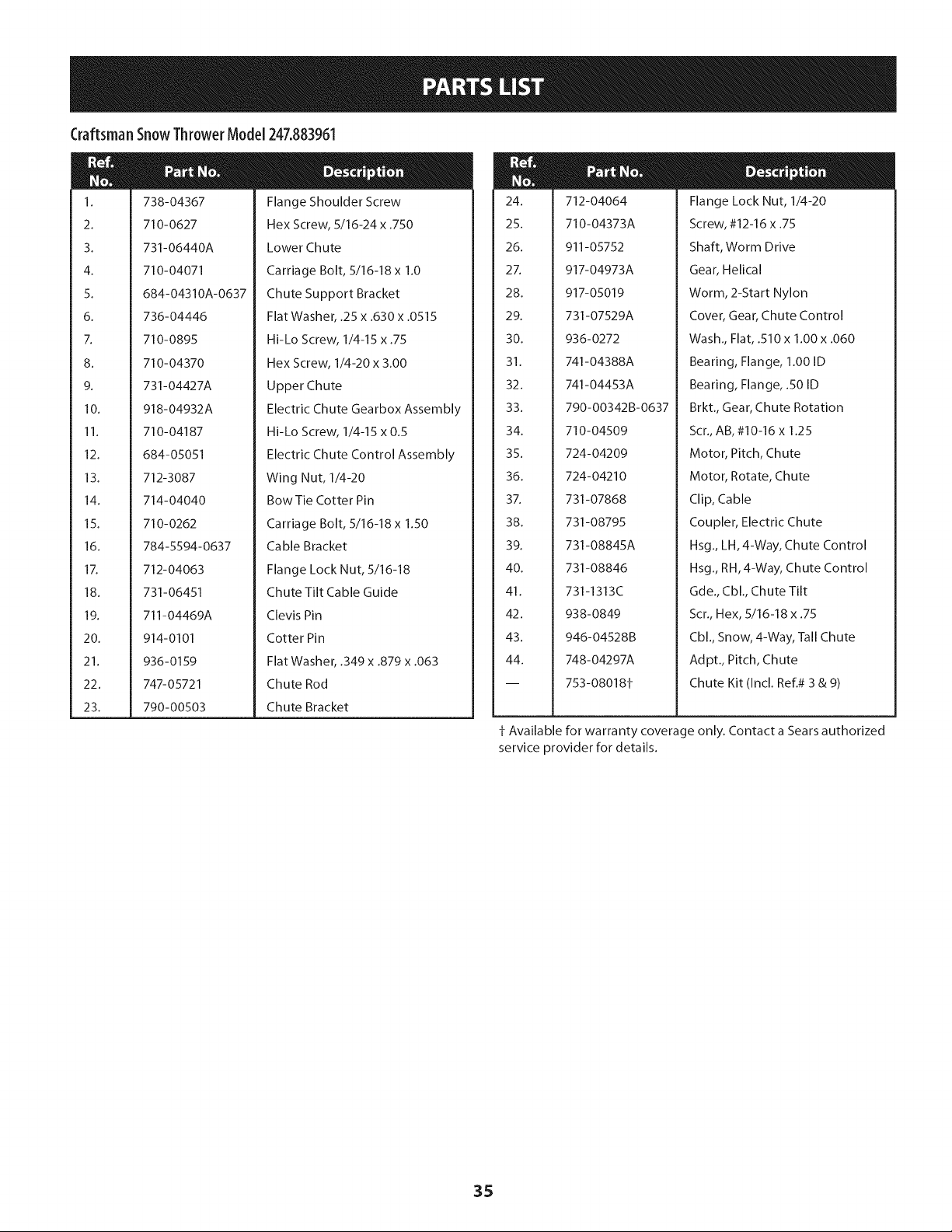
35
Craftsman EngineModel 483-SUBForSnow Model 247.883961
m
i
i 1
i
i
i
i 2
!
i
i 3
i
i
i
i 4
i
i
i 5
!
!
i
i 7
i
i
i 8
!
i
i 9
i
i
i
i 10
i
i
i 11
i
i
i
i 12
i
i
i 13
!
i
i 14
i
i
i
i 15
!
i
i 38
i
i
i
i 39
i
710-04915
951-11339
710-04915
951-10757
951-11595
731-05632
951-10637
951-11302
710-04914
951-11181
951-11321
710-04968
951-11338
712-05015
951-11311
710-04915
II _ o 0
Bolt M6x12
Muffler Shield
Bolt M6x12
Throttle Control Knob
Control Panel
Key
Key Switch Assembly
Choke Knob
Bolt M6xlO
Exhaust Pipe Shield
Carburetor Heat Shield
Bolt M6x16
MuFfler Assembly
Nut, M8
Throttle Control Assembly
Bolt M6x12
36
Craftsman EngineModel 483-SUBForSnow Model 247.883961
m
129
130
131
132
133
134
135
135
136
137
138
139
147
a
b
C
d
e
f
g
h
i
I
O
m
z
710-05392
710-05056
951-11315
951-11316
951-11223
951-14023A
951-10639A
--134
951-11824
951-11304
951-11192
736-04477
712-05015
951-12760A
n/a
736-04638
710-05469
n/a
n/a
n/a
n/a
ID - o 0
Stud M6-8x100
Stud M6-8x118
Carburetor Intake Gasket
Carburetor Insulator
Carburetor Gasket
Ca rburetor Assembly
Primer Assembly
Primer Bulb
Heater Box
Choke Assembly
LockWasher
NutM6
Carburetor Rebuild Kit
(In c.i,j,p,q,r,s,t,u,v,x,z)
Choke Shaft
Choke Control Lever Washer
Fuel Shutoff Lever Screw
Choke Plate
Throttle Shaft
Throttle Plate
Gasket
131
33 0 136
135--_ 137138__0--_ 138
147-Carburetor Rebuild Kit 139_ _139
h
I
J
k
I
m
n
o
P
q
r
s
t
U
V
W
X
Y
Z
aa
n_
n_
n_
n_
n_
751-11991
951-11906
n_
n_
n_
n_
n_
n_
n_
951-11970
n_
951-11348
710-04945
951-11349
710-04938
D - o 0
Throttle Shaft Cover
Idle Jet Rivet
Idle Jet Assembly
Idle Speed Adjusting Screw
Primer Pipe
Primer Hose
Primer Hose Clamp
Carburetor Body
Float Pin
Emulsion Tube
Nickel Plated Brass Needle Valve
Main Jet
Needle Valve Spring
Float
Fuel Bowl Gasket
Fuel Bowl
Fuel Bowl Gasket
Fuel Bowl Mounting Bolt
Fuel Drain Plug Gasket
Fuel Drain Plug
37
CraftsmanEngineModel483-SUBForSnow Model 247.883961
61
141
140
44
42
4O
I
43 42
144- GasketKit- CompJete
145- GasketKit- External
146- CompleteEngine
49
38
Craftsman EngineModel 483-SUBForSnow Model 247.883961
4O
41
42
43
44
48
49
5O
51
52
53
54
55
56
57
58
59
6O
61
62
64
65
66
951-11951
951-11952
951-11953
951-11954
951-12579
951-11956
951-11373
736-04453
714-04077
951-I1958
951-I1365
951-I1342
951-I0307
715-04102
715-04092
951-I1959
951-I1376
736-04545
951-I1283
951-I1577
951-14220
951-I1340
951-11375
710-06061
D - o o
Connecting Rod Assembly
Piston
Piston Pin Snap Ring
Piston Pin
Piston Ring Set
Governor Gear/Shaft Assembly
Radial Ball Bearing
Flat Washer
Governor Shaft Clip
Governor Seal
Governor Arm Shaft
Crankshaft Kit (Inc.49,54,55,65,81)
Woodruff Key
Dowel Pin 9 X 12
Dowel Pin 7 X 14
Camshaft Assembly
Crankcase Cover Gasket
Washer
Oil Fill Plug Assembly
O-Ring
Crankcase Cover
Crankcase Cover Kit
(Inc.49,59,60,64-68)
Oil Seal
Bolt M8x38
67
68
69
70
71
73
74
75
76
77
78
79
8O
81
140
141
143
144
145
146
710-06062
710-06063
710-04968
951-11320
710-05349
951-11381
951-12073
951-11904
951-11971A
951-11341A
951-11328B
951-11350
736-04440
710-04906
951-11499
951-11968
951-11969
951-10641
951-11330A
951-11331
952Z483-SU B
D - o 0
Bolt M8x45
Bolt M8x35
Bolt M6x16
Oil Tube Support Bracket
Bolt M6x8
Oil Fill Tube O-Ring
Oil Fill Tube Assembly
Dipstick O-Ring
Dipstick Assembly
Crankcase Kit (Inc.49,52,77,81)
Short Block Assembly
(Inc.40-44,48-68,77-81,102,105,106,108
ll0,111,125,131,132,140,141)
Oil Drain Pipe
Drain Pipe Washer 10X16X1.5
Oil Drain Plug Bolt
Oil Seal
Balance Gear Assembly
Bearing
Oil Drain Asm
Gasket Kit - Complete
(Inc.52,59,65,79,81,106, 108,125,131-133)
Gasket Kit- External
(Inc.79,108,125,131-133)
Complete Engine
39
Craftsman EngineModel 483-SUBForSnow Model 247.883961
142
123
123
123
1::4
123
11o_
11s 11_
_11311s -- 112 11o
116"--_) (_ I
114 113 o
122 121 120 119
I 1 127
118 144-GasketKit-Coreplete 128
145- Gasket Kit- I:xternal
146- CompleteEngine
123
4O
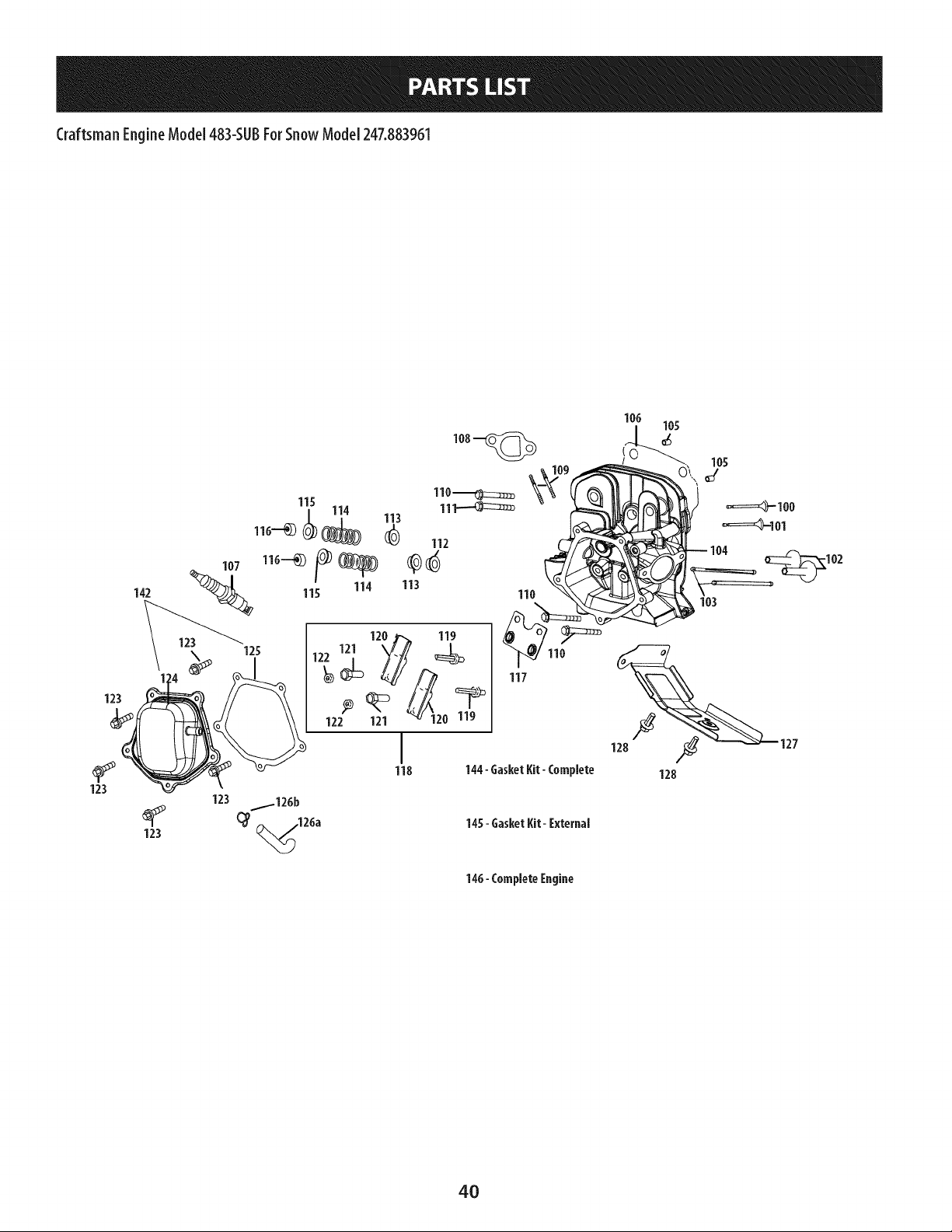
Craftsman EngineModel 483-SUBForSnow Model 247.883%1
100
101
102
103
104
105
106
107
108
109
109
110
111
112
113
114
115
951-11337
951-11337
951-11962
951-11335
951-12555
951-11329B
715-04097
951-11963
951-10292
951-11212
710-04964
951-11207
710-06064
710-06065
951-11964
951-12077
951-12078
951-12080
D _ o o
Valve Kit
Valve Kit
Tappet
Push Rod Kit
Cylinder Head Kit (Inc.106,110-112,125)
Cylinder Head Assembly
(Inc.100,101,104,106,108-112,
114-122,125,129-133)
Dowel Pin
Cylinder Head Gasket
Spark Plug/F6Rtc
Muffler Gasket
Exhaust Stud M8x48.5
Muffler Stud Assembly
Bolt MlOxl.25x87
Bolt MlOx1.25x65
Intake Valve Seal
Intake Valve Spring Retainer
Valve Spring
Exhaust Valve Spring Retainer
116
117
118
119
120
121
122
123
124
125
126a
126b
127
128
142
144
145
146
951-12081
951-11965
951-11981
710-04962
951-11966
751-11123
751-11124
710-05054
951-11220
951-11967
731-07059
726-04101
951-11317
710-04915
951-11333
951-11330A
951-11331
952Z483-SU B
D _ o o
Exhaust Lash Cap
Push Rod Guide
Rocker Arm Assembly
Bolt, Pivot
Rocker Arm
Adjusting Nut ,Valve
Pivot Locking Nut
Valve Cover Bolt
Valve Cover
Valve Cover Gasket
Breather Hose
Breather Hose Clamp
Cylinder Baffle
Bolt M6x12
Valve Cover Kit
Gasket Kit - Complete
(In c.52,59,65,79,81,106,108,125,131-133)
Gasket Kit - External
(In c.79,108,125,131-133)
Complete Engine
41
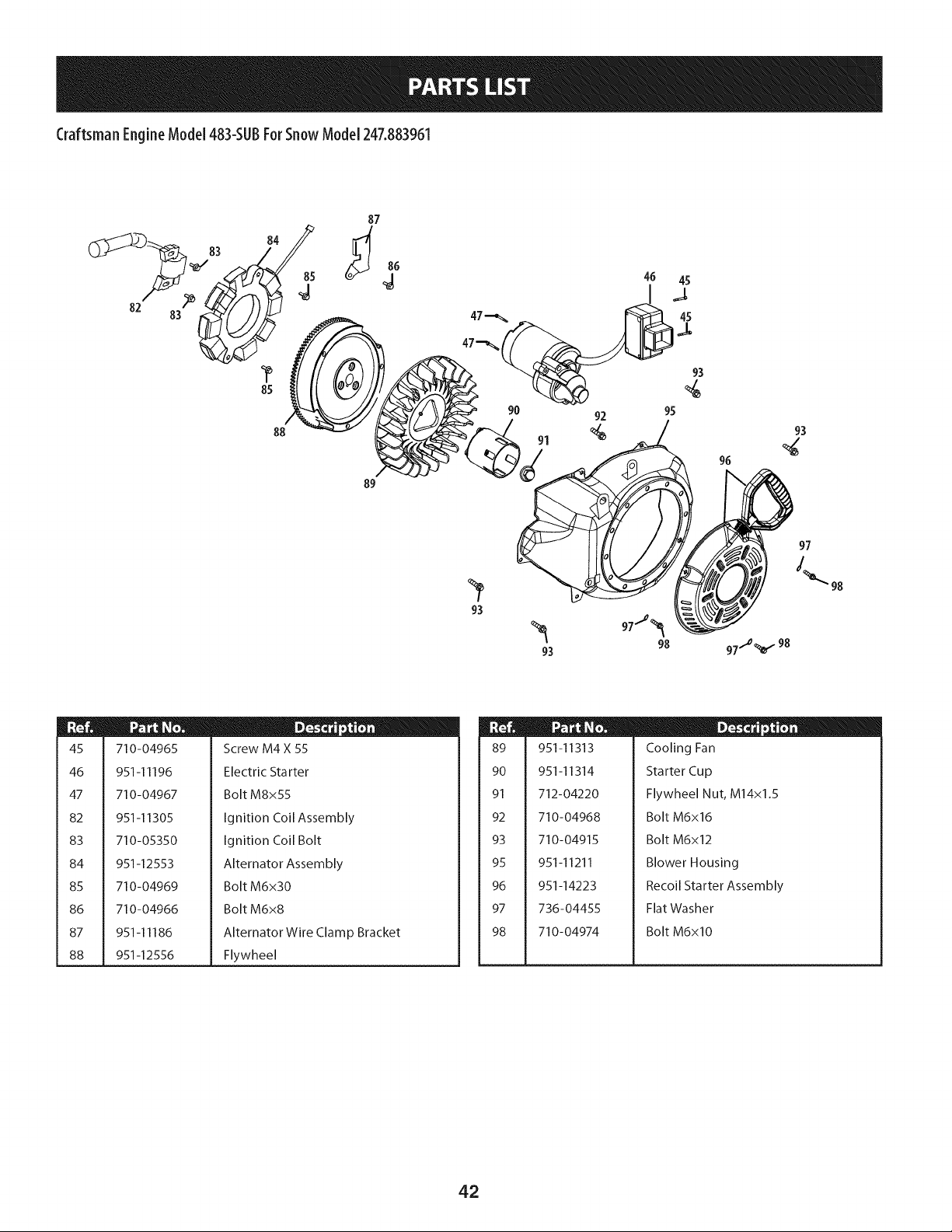
Craftsman EngineModel 483-SUBForSnow Model 247.883961
82
84
85
88
87
89
91
96
98
97
45
46
47
82
83
84
85
86
87
88
710-04965
951-11196
710-04967
951-11305
710-05350
951-12553
710-04969
710-04966
951-11186
951-12556
D - o w
Screw M4 X 55
Electric Starter
Bolt M8x55
Ignition Coil Assembly
Ignition Coil Bolt
Alternator Assembly
Bolt M6x30
Bolt M6x8
Alternator Wire Clamp Bracket
Flywheel
89
90
91
92
93
95
96
97
98
951-11313
951-11314
712-04220
710-04968
710-04915
951-11211
951-14223
736-04455
710-04974
D - o 0
Cooling Fan
Starter Cup
Flywheel Nut, M14x1.5
Bolt M6x16
Bolt M6x12
Blower Housing
Recoil Starter Assembly
Flat Washer
Bolt M6xl0
42
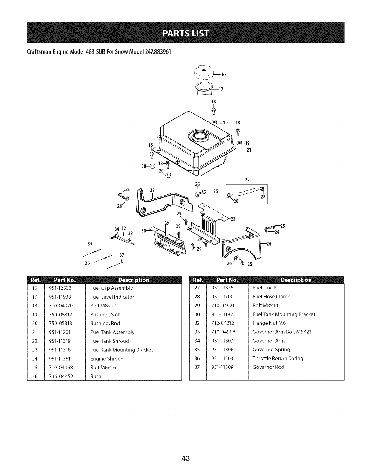
Craftsman EngineModel 483-SUBForSnow Model 247.883961
16
17
18
19
20
21
22
23
24
25
26
/25
%
26/
18
26
34 32
951-12533
951-I 1933
710-04970
750-05312
750-05313
951-11201
951-11319
951-11318
951-11351
710-04968
736-04452
D _ o o
Fuel Cap Assembly
Fuel Level Indicator
Bolt M8x20
Bushing, Slot
Bushing, Rnd
Fuel Tank Assembly
Fuel Tank Shroud
Fuel Tank Mounting Bracket
Engine Shroud
Bolt M6x16
Bush
27
28
29
30
32
33
34
35
36
37
951-11336
951-11700
710-04921
951-11182
712-04212
710-04908
951-11307
951-11306
951-11203
951-11309
D _ o 0
Fuel Line Kit
Fuel Hose Clamp
Bolt M8x14
Fuel Tank Mounting Bracket
Flange Nut M6
Governor Arm Bolt M6X21
Governor Arm
Governor Spring
Throttle Return Spring
Governor Rod
43
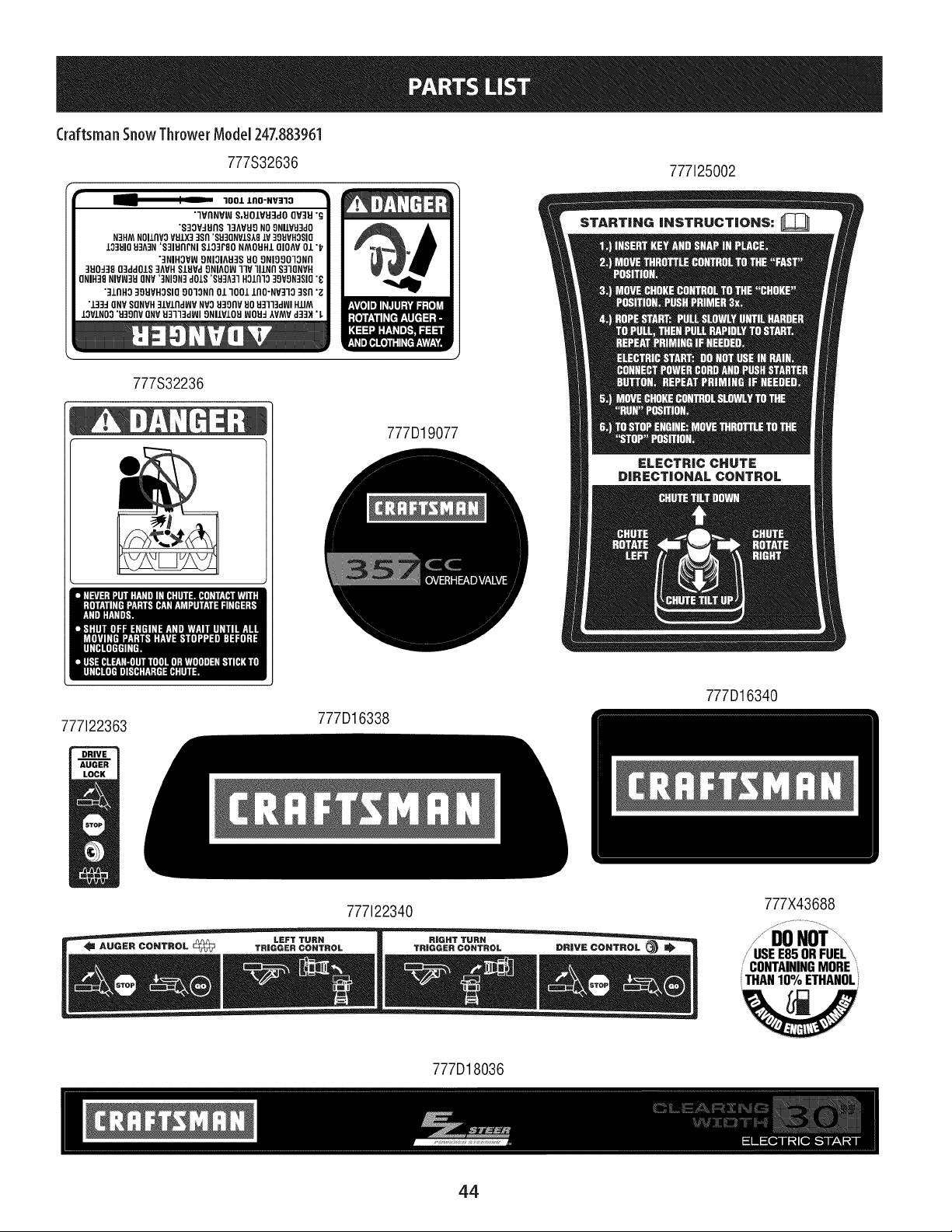
CraftsmanSnowThrowerModel 247.883961
777S32636
777125002
1001 lnO-NV:ZlO
7VnNVIN S,EIOLVEFIdOQV::IEI"g
"8:IOV:IEInSI:IAVEIONO8NIIVU:IciO
N3HMNOIlrlV3VEIIX3:]Sfl'S830NVLSA81V39UVHOSIQ
IO]UIOEI3A3N'S]IHflPNl8103F80NMOEIHIQIOAV01 "I
"3NIHOVW9NIOIAEI3S80 ONIOOOIONA
]H0:139(]3dd01S3AVHSIUVd9NIAOW11V111NflS31QNVH
ONIH::I8NIVI/J3HQNV'::INION3d01S'SU_A31HOln1039VON:ISIO7
":_11'1H339EIVHOSIQO0"lONn01 "1001lflO-NV3"lO3SR';
"13:1:1ONVSONVH:IIVlrldWVNVOU3OflVEIOU]ll]dl_l HIlM
IOVINO0"H39flVONVIJ3133d_ll9NIIV101-IWOEI:IAVMVd33H'
777S32236
777D19077
777122363
777D16338
777D16340
777122340
777D18036
777X43688
++DONoi
/'USEE85 ORFUEL'"+
CONTAININGMORE
THAN10% ETHANOL
W
44
FEDERALand/or CALIFORNIAEMISSIONCONTROLWARRANTYSTATEMENT
YOURWARRANTYRIGHTSANDOBLIGATIONS
MTD Consumer Group Inc, the United States Environmental Protection Agency (EPA), and for those products certified for sale in the state of
California, the California Air Resources Board (CARB) are pleased to explain the emission (evaporative and/or exhaust) control system (ECS)
warranty on your 2013 and later small off-road spark-ignited engine and equipment (outdoor equipment engine). In California, new outdoor
equipment engines must be designed, built and equipped to meet the State's stringent anti-smog standards (in other states, outdoor
equipment engines must be designed, built, and equipped to meet the U.S. EPA small off-road spark ignition engine regulations). MTD
Consumer Group Inc must warrant the ECSon your outdoor equipment engine for the period of time listed below, provided there has been no
abuse, neglect, or improper maintenance of the outdoor equipment engine.
Your ECS may include parts such as the carburetor, fuel-injection system, ignition system, catalytic converter, fuel tanks, fuel lines, fuel caps,
valves, canisters, filters, vapor hoses, clamps, connectors, and other associated emission-related components.
Where a warrantable condition exists, MTD Consumer Group Inc will repair your outdoor equipment engine at no cost to you including
diagnosis, parts, and labor.
MANUFACTURER'SWARRANTYCOVERAGE:
This emission control system is warranted for two years. If any emission-related part on your outdoor equipment engine is defective, the
part will be repaired or replaced by MTD Consumer Group Inc. In the event that a component is covered for longer than two years by the
Manufacturer's equipment warranty, the longer coverage period will apply.
/
OWNERSWARRANTYRESPONSIBILITIES:
As the outdoor equipment engine owner, you are responsible for performance of the required maintenance listed in your owner's manual. MTD
Consumer Group Inc recommends that you retain all receipts covering maintenance on your outdoor equipment engine, but MTD Consumer
Group Inc cannot deny warranty solely for the lack of receipts.
As the outdoor equipment engine owner, you should however be aware that MTD Consumer Group Inc may deny you warranty coverage if
your outdoor equipment engine or a part has failed due to abuse, neglect, improper maintenance, or unapproved modifications.
You are responsible for presenting your outdoor equipment engine to MTD Consumer Group Inc's distribution center or service center as soon
as the problem exists. The warranty repairs should be completed in a reasonable amount of time, not to exceed 30 days. If you have a question
regarding your warranty coverage, you should contact the MTD Consumer Group Inc Service Department at 1-800-800-7310 or at
http://su pport.mtd prod ucts.com.
GENERALEMISSIONSWARRANTYCOVERAGE:
MTD Consumer Group Inc warrants to the ultimate purchaser and each subsequent purchaser that the outdoor equipment engine is: (1)
designed, built, and equipped so as to conform with all applicable regulations; and (2) free from defects in materials and workmanship that
cause the failure of a warranted part for a period of two years.
The warranty period begins on the date the outdoor equipment engine is delivered to an ultimate purchaser or first placed into service.
Subject to certain conditions and exclusions as stated below, the warranty on emission-related parts is as follows:
1. Any warranted part that is not scheduled for replacement as required maintenance in the written instructions supplied is warranted for
the warranty period stated above. If the part fails during the period of warranty coverage, the part will be repaired or replaced by MTD
Consumer Group Inc according to subsection (4) below. Any such part repaired or replaced under warranty will be warranted for the
remainder of the period.
2. Any warranted part that is scheduled only for regular inspection in the written instructions supplied is warranted for the warranty period
stated above. Any such part repaired or replaced under warranty will be warranted for the remaining warranty period.
3. Any warranted part that is scheduled for replacement as required maintenance in the written instructions supplied is warranted for the
period of time before the first scheduled replacement date for that part. If the part fails before the first scheduled replacement, the part
will be repaired or replaced by MTD Consumer Group Inc according to subsection (4) below. Any such part repaired or replaced under
warranty will be warranted for the remainder of the period prior to the first scheduled replacement point for the part.
Repair or replacement of any warranted part under the warranty provisions herein must be performed at a warranty station at no charge
to the owner.
4.
5. Notwithstanding the provisions herein, warranty services or repairs will be provided at all of our distribution centers that are franchised to
service the subject engines or equipment.
6. The outdoor equipment engine owner will not be charged for diagnostic labor that is directly associated with diagnosis of a defective,
emission-related warranted part, provided that such diagnostic work is performed at a warranty station.
7. MTD Consumer Group Inc is liable for damages to other engine or equipment components proximately caused by a failure under
warranty of any warranted part.
8. Throughout the off-road engine and equipment warranty period stated above, MTD Consumer Group Inc will maintain a supply of
warranted parts sufficient to meet the expected demand for such parts.
9. Any replacement part may be used in the performance of any warranty maintenance or repairs and must be provided without charge to
the owner. Such use will not reduce the warranty obligations of MTD Consumer Group Inc.
10. Add-onormodifiedpartsthatarenotexemptedbytheAirResourcesBoardmaynotbeused.Theuseofanynon-exemptedadd-onor
modifiedpartsbytheultimatepurchaserwillbegroundsfordisallowingawarrantyclaims.MTDConsumerGroupIncwillnotbeliableto
warrantfailuresofwarrantedpartscausedbytheuseofanon-exemptedadd-onormodifiedpart.
WARRANTEDPARTS:
The repair or replacement of any warranted part otherwise eligible for warranty coverage may be excluded from such warranty coverage if
MTD Consumer Group Inc demonstrates that the outdoor equipment engine has been abused, neglected, or improperly maintained, and that
such abuse, neglect, or improper maintenance was the direct cause of the need for repair or replacement of the part. That notwithstanding,
any adjustment of a component that has a factory installed, and properly operating, adjustment limiting device is still eligible for warranty
coverage. Further, the coverage under this warranty extends only to parts that were present on the off-road engine and equipment purchased.
The following emission warranty parts are covered (if applicable):
1. Fuel Metering System
Cold start enrichment system (soft choke)
Carburetor and internal parts (or fuel injection system)
Fuel pump
Fuel tank
2. Air Induction System
Air cleaner
Intake manifold
3. Ignition System
Spark plug(s)
Magneto ignition system
4. Exhaust System
Catalytic converter
SAI (Reed valve)
5. Miscellaneous Items Used in Above System
Vacuum, temperature, position, time sensitive valves and switches
Connectors and assemblies
6. Evaporative Control
Fuel hose
Fuel hose clamps
Tethered fuel cap
Carbon canister
Vapor lines
050790 Rev.A
Congratulationsonmakingasmartpurchase.YournewCraftsman®productisdesignedandmanufacturedforyearsof
dependableoperation.Butlikeall products,it mayrequirerepairfromtimeto time.That'swhenhavinga RepairProtection
Agreementcansaveyoumoneyandaggravation.
Here'swhat the Repair ProtectionAgreement_ includes:
[] Expertservice byour10,000professionalrepairspecialists
[] Unlimitedserviceand nocharge forpartsandlaboronallcoveredrepairs
[] Productreplacementupto $1500if yourcoveredproductcan'tbefixed
[] Discountof 25%from regularpriceof serviceandrelatedinstalledpartsnot coveredbythe agreement;also,25%off
regularpriceof preventivemaintenancecheck
[] Fasthelpby phone- wecallit RapidResolution- phonesupportfromaSearsrepresentative.Thinkof usasa"talking
owner'smanual."
Onceyoupurchasethe RepairProtectionAgreement,a simplephonecallisallthat it takesfor youto scheduleservice.You
cancallanytimedayornight,orscheduleaserviceappointmentonline.
TheRepairProtectionAgreementisa risk-freepurchase.If youcancelfor anyreasonduringthe productwarrantyperiod,
wewill provideafull refund.Or,a proratedrefundanytimeafterthe productwarrantyperiodexpires.PurchaseyourRepair
ProtectionAgreementtoday!
Somelimitations and exclusionsapply. Forpricesand additional informationin the U.S.A.call 1-800-827-6655.
_Coveragein Canadavarieson someitems. Forfull detailscall SearsCanadaat 1-800-361-6665.
SearsInstallationService
ForSearsprofessionalinstallationof homeappliances,garagedooropeners,waterheaters,andothermajorhomeitems,in
the U.S.A.orCanadacall1-800-4-MY-HOME®.
47

Your Home
For troubleshooting, product manuals and expert advice:
managernylife
www.managemylife.com
For repair - in your home - of all major brand appliances,
lawn and garden equipment, or heating and cooling systems,
no matter who made it, no matter who sold it!
For the replacement parts, accessories and
owner's manuals that you need to do-it-yourself.
For Sears professional installation of home appliances
and items like garage door openers and water heaters.
1-800-4-MY-HOME ® (1-800-469-4663)
Call anytime, day or night (U.S.A. and Canada)
www.sears.com www.sears.ca
Our Home
For repair of carry-in items like vacuums, lawn equipment,
and electronics, call anytime for the location of your nearest
Sears Parts & Repair Service Center
1-800-488-1222 (U.S.A.) 1-800-469-4663 (Canada)
www.sears.com www.sears.ca
To purchase a protection agreement on a product serviced by Sears:
1-800-827-6655 (U.S.A.) 1-800-361-6665 (Canada)
Para pedir servicio de reparaci6n
a domicilio, y para ordenar piezas:
1-888-SU-HOGAR ®
(1-888-784-6427)
www.sears.com
Au Canada pour service en frangais:
1-800-LE-FOYER Mc
(1-800-533-6937)
www.sears.ca
® Registered Trademark / TMTrademark of KCD IP, LLC in the United States, or Sears Brands, LLC in other countries
® Marca Registrada ! TMMarca de Fabrica de KCD IP, LLC en Estados Unidos, o Sears Brands, LLC in otros paises
MCMarque de commerce ! MDMarque deposee de Sears Brands, LLC


