
Loading ...
Loading ...
Loading ...
Part number 550-100-214/1220
– 30 –
CONDENSING GAS BOILER — 110/155 Advanced Manual
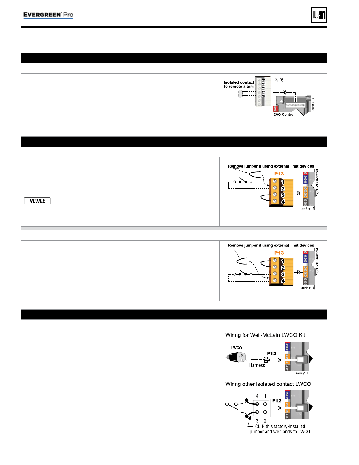
H. Alarm contacts – OPTIONAL
Terminal Block P16 #4 & #5 (EVG control module)
1. The control’s alarm dry contact (P16, terminals 4 and 5) closes when the
boiler enters manual lockout only.
2. Connect these terminals for remote alarm notifi cation.
3. Contact electrical ratings: 24 VAC or less; 0.5 amp or less.
See Figure 15, page 34 for details
I. External limits – OPTIONAL
To cause MANUAL reset: Terminal Block P13 #1 & #2 (EVG control module)
EVG control will require manual reset after circuit is interrupted
1. Remove factory-installed jumper and connect isolated contacts of external
limits across P13 pins 1 and 2 to cause the control to enter manual reset lock-
out if the limit circuit opens. The limit must close and the control must be
manually reset using the procedure given in this manual. See drawing at right
and wiring diagram ( Figure 15, page 34 ).
The control will lockout when a limit in its manual reset circuit opens
(P13 pins 1 & 2). The control activates its alarm terminals and shuts
the boiler off. An operator (user or technician) must manually reset
the control to resume heating. Cycling power on and off will NOT
reset the control.
See Figure 15, page 34 for details
To cause AUTOMATIC reset: Terminal Block P13 #3 & #4 (EVG control module)
EVG control will reset automatically after circuit is interrupted
1. Remove factory-installed jumper and connect isolated contacts of external
limits across P13 pins 3 and 4 to cause the control to shut down the burner
on limit opening, then automatically restart 150 seconds after the limit closes.
2. See drawing at right and wiring diagram ( Figure 15, page 34 ).
See Figure 15, page 34 for details
J. Low water cutoff – WHEN REQUIRED
Terminal Block P12 (EVG control module)
1. Install a low water cut-off when required.
2. Wiring Weil-McLain LWCO Kit
a. When possible, use the Weil-McLain Low water cut-off kit listed in the
Boiler manual replacement parts section. It includes a probe-type low
water cut-off and provides a simple harness connection for the wiring.
b. Connect as shown at top right and in the control wiring diagram ( Fig-
ure 15, page 34 ).
c. The Weil-McLain Low water cut-off kit is included with the boiler.
3. Wiring another LWCO — must have isolated contact
a. Other low water cut-offs can be used with the EVG only if the device uses
an isolated contact for the LWCO function.
b. Connect as shown at bottom right.
See Figure 15, page 34 for details
Field wiring (see wiring diagram, Figure 15, page 34 )(continued)
Loading ...
Loading ...
Loading ...