LOOP MIXER
Englis h
G6047095R0-00
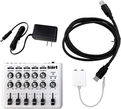
AC Adaptor DM2S Adaptor Owner’s Manual
*G6047095R0-00*
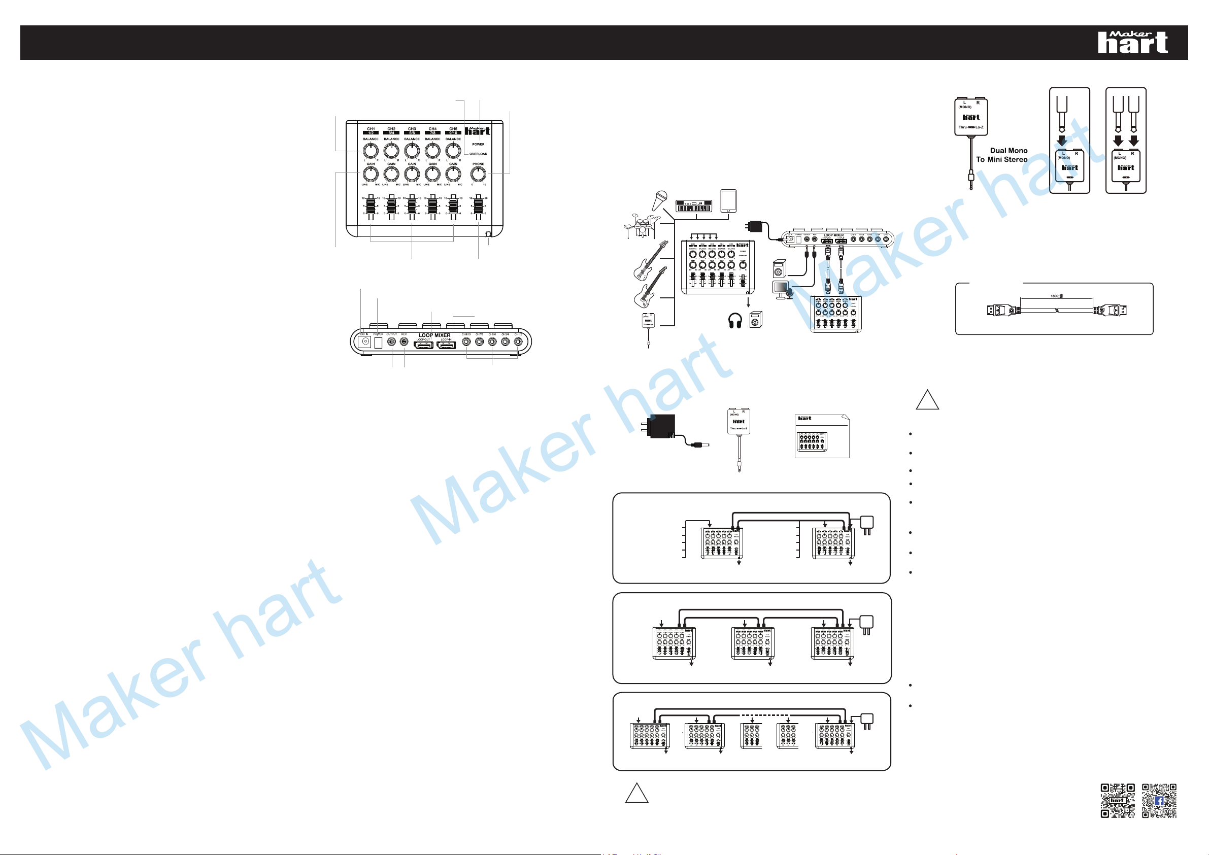
MONO STEREO
L R
Thru Lo-ZThru Lo-Z
■SPECIFICATIONS
■CONNECTIONS
■PANEL DESCRIPTIONS
■OPERATION
■LOOP MIXER
LOOP CONNECTION
Be sure to use LOOP CABLE only specified for this product.
(Only for LOOP MIXER)
■OPTION
mm
■DM2S Adapter
■IMPORTANT NOTES
■Accessory
IN
OUT
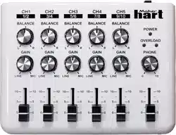
1. BALANCE Knob
2. OVERLOAD Indicator
3. POWER Indicator
4. PHONES Knob
5. GAIN Knob
6. CHANNEL VOLUME Slider
7. MASTER VOLUME Slider
8. PHONES Jack
9. AC ADAPTOR Jack
10. POWER Switch
11. LOOP OUT Jack
12. LOOP IN Jack
13. OUTPUT Jack
14. REC OUT Jack
15. CH1~5 INPUT Jack
LOOP CABLE
!
Be sure to use only the AC adaptor supplies with the unit. Use of any
other AC adaptor could result in damage, malfunction, or electric shock.
POWER SUPPLY
Before connecting this unit to other devices, turn off the power to all units; this will help
prevent damage or malfunction.
Do not use this unit on the same power circuit with any device that will generate line
noise ; an electric motor or variable lighting system for example.
Avoid damaging the power cord: do not step on it, place heavy objects on it, etc.
When disconnecting t
he AC adaptor from the power outlet, grasp the plug itse lf;
never pull on the cord.
If the unit is to remain unused for an extended period of time, unplug the power cord.
PLACEMENT
Do not subject the unit to temperature extremes (eg., direct sunlight in an enclosed
vehicle).
Avoid using or storing the unit in dusty or humid areas, or areas that are subject to
high levels of vibration.
Using the unit near power amplifiers (or other equipment containing large power
transformers) may induce hum.
MAINTENANCE
For everyday cleaning wipe the unit with a soft, dry cloth or one that has been slightly
dampened with water. To remove stubborn dirt, use a mild, nonabrasive detergent.
Afterwards, be sure to wipe the unit thoroughly with a soft, dry cloth.
Never use benzene, thinners, alcohol or solvents of any kind, to avoid the possibility of
discoloration and/or deformation.
ADDITIONAL PRECAUTIONS
When the following situation occur please turn the power off Immediately:
The AC adaptor or the power-supply cord has been damaged; or If smoke or unusual
odor occurs.
Objects have fallen into, or liquid has been spilled onto t
he unit; or The unit has been
exposed to rain(or otherwise has become wet); or The unit does not appear to
operate normally or exhibits a marked change in performance.
MAKER HART INDUSTRY CORP.
2F., NO.3, LN. 263, CHONGYANG RD., NANGANG DIST.,
Email:info@makerhart.com
http://www.makerhart.com
https://www.facebook.com/Makerhart2015/
TAIPEI CITY 11573, TAIWAN (R.O.C)
G6047059R0-
G6047059R0-0
LOOP MIXER
Owner’s Manual
5 STEREO / 10 MONO CHANNEL MIXER
Owner’s Manual 5 STEREO / 10 MONO CHANNEL MIXER
For Person
CH1/2~CH9/10
How to use ...
SPEAKER / PHONES
PHONES
PHONES
ADAPTOR
9V 1A
For Bands
Example :
LOOP-OUT LOOP-IN
LOOP-IN LOOP-OUT
EG
BASS
MIC
DRUM
KEYBOARD
EG
BASS
MIC
DRUM
KEYBOARD
CH1/2 CH3/4
PHONES PHONES
LOOP-OUT LOOP-IN
LOOP-IN
CH1/2 CH3/4
PHONES
ADAPTOR
9V 1A
LOOP-OUT LOOP-IN
LOOP-OUT
CH5/6
Example :
PHONES PHONES
LOOP-IN
CH1/2 CH3/4
CH5/6 CH7/8
PHONES
ADAPTOR
9V 1A
LOOP-IN
LOOP-OUT
CH9/10
Example :
LOOP-OUT
!
■ FEATURES
1. BALANCE Knob
This knob adjust the stereo input balance for each channel. At the center position,
the left and right signals are at the same level. Rotating the knob clockwise or
counterclockwise will shift the sound field to the right or left respectively.
2. OVERLOAD Indicator
This indicator light when the mixed signal level is too high. If these LEDs light
frequently, lower channel counterclock wise.
*These indicators are not affected by the position of the MASTER volume slider.
*These indicators light at 6 dB below the clipping level
(the point at which distortion becomes audible)
3. POWER Indicator :
This indicator lights when the LOOP MIXER is turned on.
4. PHONES Knob : This knob controls the headphone volume.
*
5. GAIN Knob : This knob adjust the input volume for each channel. They are
used to optimize the signal level to avoid distortion. Rotating a GAIN knob clockwise
will increase the volume, while rotating it counterclockwise will decrease the volume.
When a microphone is connected to one of the INPUT jack, be sure to rotate the
corresponding GAIN knob completely clockwise (near to the “MIC” position).
* Each GAIN knob controls the L/R signals in each channel simultaneously.
The headphone volume is not affected by the Position of the MASTER Volume slider.
6. CHANNEL VOLUME Slider :
This slider provide volume control for each channel. Set these sliders relative to one
another to achieve the best audio mix.
* Each VOLUME slider controls the L/R signals in each channel
simultaneously.
7. MASTER VOLUME Slider : This slider adjusts the overall output of the
LOOP MIXER.
*The MASTER slider does not affect the output level of the REC OUT jacks or the
PHONES jack.
8. PHONES Jack (Stereo Mini Type) : Connect stereo headphones to this
jack.
9. AC ADAPTOR Jack : Connect an AC adaptor to this jack.(Be sure to use the
adaptor specified for your country)
10. POWER Switch : Power ON/OFF of LOOP MIXER.
11. LOOP OUT Jack : Connect LOOP CABLE to another LOOP MIXER’s
LOOP IN Jack. You can rehearse or jam while monitoring with head phones.
12. LOOP IN Jack : Connect LOOP CABLE to another LOOP MIXER’s LOOP
OUT Jack. You can rehearse or jam while monitoring with headphones.
13. OUTPUT Jack (Stereo Mini Type) : This jack provide output of the final
mixed signals. They can be connected to a PA system, or to the inputs of another mixer.
14. REC OUT Jack (Stereo Mini Type) : This jack is convenient for
recording direct to a record device. (Convenient further still because the
output level is
not
affected by the MASTER Volume slider)
15. CH1~5 INPUT Jack (Stereo Mini Type) : Devices (electronic
instruments or mics, for example) with TRS mini plug should be connected to these
inputs. ( To connect a monaural device, you can use the plug adaptor supplies with the
unit)
Thru : Pass Through (Normal Mode).
Lo-Z : When a high impedance equipped source (like an electric guitar) causes noise
or crosstalk, switch to Lo-Z (low impedance) then the noise or crosstalk level can be
reduced.
*Note : Switching to Lo-z,the input signal level will be reduced.
Please refer to our website for our locations list where to buy.
Stereo 5 in/2 out Configuration
5 stereo devices on LOOP MIXER can connect up to 10 mono device.
Microphone Setup
With the inclusion of GAIN knobs, the LOOP MIXER can accommodate a variety of
signais from microphone to Line level.
Overload lndicators
The L/R OVERLOAD LEDs allow you to set the best signal level for optimum audio
performance.
REC OUT Jacks
Connection to a recording device can be made through these jacks
Phones Jack
Stereo headphones can be connected to this jack for convenient mix monitoring.
LOOP Jack
Through loop cable can be connected plurality LOOP MIXER, and on the respective
LOOP MIXER, you can monitor and adjust the sound volume of other devices freely, and
ont affect the overall mix effect.
Thank you for purchasing the LOOP MIXER. To take full advantage of the LOOP MIXER,
and to ensure Proper operation, please read this owner’s manual carefullly.
Nominal Input Level
INPUT (1 to 5)
50dBm ~ +4dBm
Input Impedance
20 kΩ (Stereo) / 10 kΩ (Mono)
Nominal Output Level
OUTPUT 0dBm
REC OUT -10dBm
Output Impedance
OUTPUT 1kΩ
REC OUT 1kΩ
Headphones Output
0.1mW (33Ω load)
Total Harmonic Distortion
0.05% or less
Indicators
Power indicator
Overload Indicator (L/R)
Power Supply
AC Adaptor (DC 9V)
Current Draw
65mA (at maximum)
Controls
BALANCE Knob x 5
GAIN Knob x 5
Channel VOLUME Sliderx 5
PHONE Knob x 1
Master Volume Slider x 1
POWER Switch
Connectors
<Front>
PHONES jack(Stereo mini type)
<Rear>
Input (L/R) x 5 (Stereo mini type)
Output (L/R) x 1 (Stereo mini type)
REC OUT (L/R) x 1 (Stereo mini type)
AC Adaptor jack (DC 9V)
LOOP IN jack x 1
LOOP OUT jack x 1
Dimensions
175(W) x 130(D) x 30 (H) mm/
6.9”(B) x 5.1”(T) x 1.2”(H)
Weight
295g/10.4oz
1. Switch off the LOOP MIXER and all the units to be connected.
2. Make all the necessary connections. Set the BALANCE knob of each channel to the
center position and the GAIN knob of each channel to the ”LINE” position. Set each
Channel VOLUME slider to “10 ” and the MASTER Volume slider to the “0” position.
3. Switch on all the units connected to the LOOP MIXER.
4. Switch on the LOOP MIXER.
5. Slowly raise the MASTER Volume slider to an appropriate level.
6. Use the GAIN knobs to adjust input sensitivity for each channel.
*For minimum noise and/or distortion, set the levels so the OVERLOAD indicators light
only briefly on input peaks.
7. Adjust the L/R input balance of each channel using the BALANCE knobs.
8. Adjust the channel levels relative to one another using the Channel VOLUME sliders.
9. Set the overall output volume using the MASTER slider.
Maker hart Maker hart Maker hart