Scorpio
Premium Portable Mixer-Recorder
User Guide v9.50
Scorpio User Guide 1

Table of Contents
Welcome to Scorpio 3
Panel Views 4
Home Screen 10
Channel Screen 12
Virtual Keyboard 16
Phrase Manager 17
Menus 18
Power 19
Channel Setup 21
Channels 13-32 23
Buses 24
Outputs 26
Limiters 31
Automixer 33
Meters 36
Timecode 38
Record/Play 40
Q-marks 42
Files 43
Frame.io 50
Slate/Coms/Returns 53
SuperSlot 55
SL-2 55
SL-2 Options 59
SL-6 62
SL-6 Options 67
Receiver Setup Screens 68
A20-Nexus/A20-Nexus Go 77
System 78
Plugins 81
Noise Suppression Plugins 83
Controllers 86
Supported Third-Party Controllers 93
Toggle Switch Action 95
Menu + PFL Switch Action 96
Front Panel Shortcuts 97
USB Keyboard 99
X-Keys® Programmable Keypads, Sticks & Keyboards 100
SD-Remote 101
Quick Setup 116
USB-A 116
USB-C 116
Dante 117
Specifications 118
Legal Notices 122
Warranty 125
Glossary 126
Welcome to Scorpio
Scorpio User Guide 2

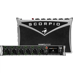
Scorpio is a 32 channel, 36 track mixer-recorder and the most powerful product ever designed by Sound Devices. With 16 mic/line
preamplifiers, 32 channels of Dante in and out, AES in and out, 12 analog outputs and multiple headphone outputs, Scorpio is
well-suited for any production scenario. Since its release in April 2019, Scorpio has received the 56th CAS Outstanding Product in
Production Award, the 2020 AMPS Excellence in a Production Audio Project Technical Award, PSNEurope Best of Show Award at
IBC2019, Editor’s Choice 2019 Award from Professional Audio, and Resolution Magazine Award for Best Recorder, 2019.
● 16 ultra low-noise, 8-Series microphone preamplifiers
● 32 channels, 12 buses, 36 tracks
● 32 channels of Dante I/O
● 256 GB internal SSD, 2 SD card slots
● USB-A and C ports for SD-Remote app, linear fader control via MCU, keyboard, and file transfer
● Dugan Automixing/MixAssist for up to 16 channels
● Optional NoiseAssist and CEDAR sdnx noise suppression plugins
● Optional integrated digital wireless with the A20-Nexus, SL-2 (plus SuperSlot receivers), or SL-6 (plus SuperSlot
receivers)
We want to thank you for your direct contribution to this product’s success. Countless conversations were shared with industry
professionals regarding workflows, frustrations, wants, and needs. The knowledge obtained from these conversations drove the
design and engineering of the Scorpio.
Our friendly and knowledgeable support team, based in the USA and the UK, is here for all your questions and comments. Our job is
to make your job easier.
We are honored to be part of your kit.
Sincerely,
Sound Devices
Scorpio User Guide 3
Panel Views
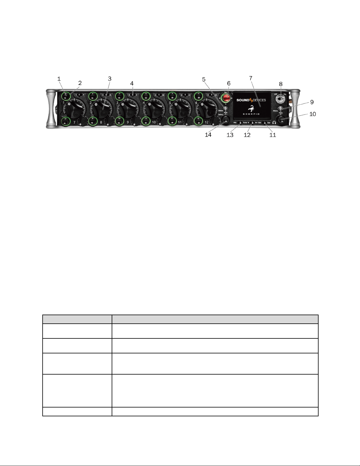
Front Panel
1: Channel Trim
Turns the channel on/off and sets the input sensitivity for the channel. To conserve power, turn off unused channels by rotating
channel trim fully counterclockwise. Channel 13-32 trims are accessible via the Channels 13-32 menu or using */** + PFL switch
shortcuts. Use Toggle Switch Actions to set the Select and /or HP knobs as trims for Ch 13,14.
2: Channel LED Ring
Provides visual indication of channel signal condition, solo and mute, and whether a channel is on or off.
3: Channel Fader
Controls the audio level of the channel as it contributes to the L/R mix and any destinations selected in routing as “Post”. Channel
13-32 faders are accessible via the Channels 13-32 menu or using */** + PFL switch shortcuts. Use Toggle Switch Actions to set the
Select and /or HP knobs as faders for Ch 13,14.
4: PFL Switch
Pre/Post Fade Listen selects the channel in the headphones for Pre/Post Fade Listen while simultaneously entering the channel
screen. Also used for accessing virtual keyboard for channel naming and various shortcuts. Channel 13-32 PFLs are accessible via
the Channels 13-32 menu or using */** + PFL switch shortcuts.
Use Toggle Switch Actions to set the Select and /or HP knobs as PFLs for Ch 13,14.
5: Meter Button
Push to view and select various metering presets. Used with Select Knob. Press again to return to Home Screen. Push with channel
Select switched 1-12 for shortcut to Meters Preset 1-12. Push and rotate HP knob to zoom meter scale. Push and Push HP knob to
access Receiver Overview screen if a SuperSlot accessory is connected.
6: Transport Controls
A joystick (with its illuminated LED ring) on the front panel is used to perform various transport control functions. (See table). The
ring LED will flash orange indicating post roll while writing to media.
Function
Action
Record
Push up the Transport control to begin recording a new file. The LED ring illuminates red while
recording is underway.
Stop
Press in the Transport control to stop recording or playback. While in standby, press and hold to
display next take name.
Play
Push down on the Transport control to begin playback of the last file recorded or file currently
loaded. While in playback, push down again to pause playback. The LED ring as well as the active
file in the display will flash to indicate that Pause is active. Push down again to continue playback.
Rewind/Load Previous Take
While in standby, push left to load the previous take. While in playback, push and hold left to
rewind.
When the Scorpio is playing back or paused, moving the joystick to the left (<<) rewinds at 2x
speed, then after holding for 5 seconds, it increases to 16x speed. Push Left while holding Select
to delete the current Q-mark
Fast Forward / Load Next Take
While in standby, push right to load the next take. While in playback, push and hold right to rewind.
Scorpio User Guide 4

When the Scorpio is playing back or paused, moving the joystick to the right (>>) fast forwards at
2x speed, then after holding for 5 seconds, it increases to 16x speed.. Push right while holding
Select to add a Q-mark.
Scrub
While playing or paused, press the headphone knob >0.5 s to enter Scrub mode. Then rotate
clockwise for fast forward or counter-clockwise for rewind speeds of 0x, 1/8x, 1/4x, 1/2x, 1x, 2x,
4x, 8x, and 16x. The audio may be heard in scrub mode up to 2x speed.
7: LCD Display
8: Power Switch/LED Indicator
Turns the power on and off. Switch LED ring indicates the following:
1. Power condition: green = good, yellow = warning, red = shutdown imminent.
2. Flashing blue = power is off and holding timecode.
3. Continuous blue = booting up.
4. Flashing yellow = unit is off and charging L-mount batteries.
5. Continuous yellow = unit is off and both L-mount batteries are fully charged.
9: Menu Button
Push to enter the Main menu. Also used to exit menus. The Menu button will flash red to indicate clipping on the headphones. Press
with Channel Select switches 1-12 for shortcuts to Menu Favorites 1-12.
10:. Headphone Knob
1. Rotate to control headphone volume. Can be disabled. See System > Headphone Volume Lock.
2. Press to open headphone preset menu and select.
3. Menu navigation and push to select.
4. Press Menu and HP knob to enter Take List.
5. Press > 0.5 s during playback to enter audio scrub mode.
Press with Channel Select switches 1-12 for shortcuts to HP Presets 1-12.
Any output getting headphone left or right signals will see changes to hp levels.
11: Rtn/Fav Switch
Toggle Rtn and Fav actions. Soft button for menus.
Mappable functions via the Toggle Switch Action menu.
12: */** Switch
Shortcut with PFL switch to access channels 13-24 and 25-32. Soft button for menus.
Mappable functions via the Toggle Switch Action menu.
13: Mic/Tone Switch
Toggle slate mic and tone generator. Soft button for menus.
Hold Select then activate Tone switch for L-Ident tone.
Mappable functions via the Toggle Switch Action menu.
14: Select Knob
1. Push to view Outputs list, rotate and push to Select Output Screen. Push Meter Button to return to Home Screen.
2. Rotate to select track in display, push both Meter and Select at the same time to arm/disarm track. While holding the
Meter
3. Button, multiple consecutive tracks may be armed by holding in the Select Knob and rotating.
4. Use with Meter Button to scroll through meter views then push to Select.
5. Push with Channel Select switches 1-12 for shortcut to Bus 1-10, L,R routing.
6. Menu navigation and push to Select.
7. Hold then press >>, <<, to add, delete Q-marks during recording and playback.
Scorpio User Guide 5
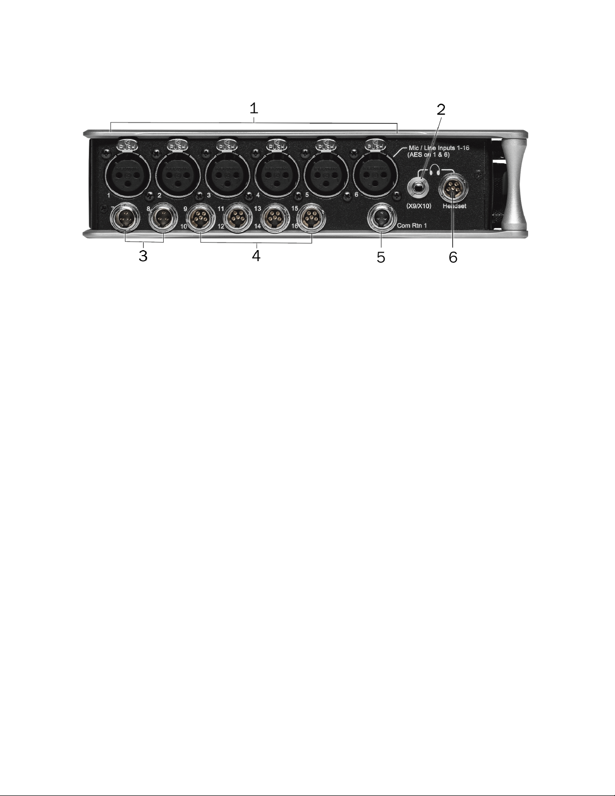
Left Side Panel
1: Inputs 1-6 female XLR Jacks
Active-balanced analog microphone or line-level inputs. Inputs 1 and 6 can also accept AES3 or AES42 signal. [pin-1 = ground,
pin-2 = hot (+), and pin-3 = cold (-)]
110 ohm cables should be used for AES3 or AES42 inputs.
2: Headphone (X9/X10) 3.5 Jack
Unbalanced output and TRS headphone output. Warning! This output can drive headphones to potentially dangerous levels.
Routing determined in the Outputs menu. [Sleeve = ground, tip = left (X9), ring = right (X10)]
3: Mic/Line Inputs 7-8 TA3 Jacks
Active-balanced analog microphone or line-level inputs. [pin-1 = ground, pin-2 = hot (+), pin 3 = cold (-)]
4: Mic/Line Inputs 9-16 TA5 Jacks
Active-balanced analog microphone or line-level inputs. [pin-1 = ground, pin-2 = Ch.1 +, pin-3 = Ch.1 -, pin-4 = Ch.2 +, pin-5 = Ch. 2
-]
5: Com Rtn 1 TA3 Jack
Balanced connection for Com Return 1 audio input. [pin-1 = Ground, pin-2 = hot (+), pin-3 = cold (-)]
6: Headphone/Headset TA5 Jack
Headphone and slate microphone connections [pin-1 = HP right, pin-2 = HP left, pin-3 = ground, pin-4 = Mic -, pin-5 = Mic+]
Route HP-L and HP-R to X9/X10 to control headphone level with the headphone knob and to send headphone signal to the TA5
output.
Scorpio User Guide 6
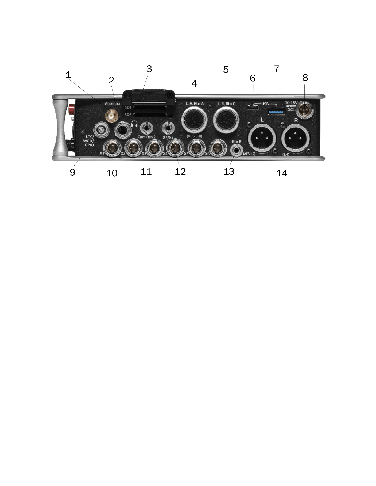
Right Side Panel
1: Antenna RP-SMA-Male Connector
Connects to included external antenna for Bluetooth LE.
2: ¼” Headphone Jack
1/4-inch TRS headphone output. This output is always fed by the headphone source levels. Warning! This output can drive
headphones to potentially dangerous levels. [Sleeve = ground, tip = left, ring = right]
3: SD 1 and 2 Card Slots
Insert SD card media for recording. Insert label side down.
4 & 5: L,R,RTN A (AES 5-8) and C 10-pin Jacks
Each connection includes a pair of outputs and a stereo unbalanced return input. Analog Output levels are selected between Line,
-10, and Mic levels in Main menu > OUTPUTS section. 10-pin A outputs can be set to send AES3 digital signals (AES 5-8). Output
may be sourced from L,R or any of the 10 mix buses in Main menu > OUTPUTS.
6: USB C Port
1. File transfer.
2. 2-in/2-out USB audio streaming.
7: USB A Port
1. USB keyboard.
2. USB to SD-Remote Android app.
3. USB to the CL-16, CL-12, and approved 3rd party fader controllers.
4. Supports USB hubs.
5. Jam A20-Mini Timecode.
8: 10-18v DC1 TA4 Jack
Accepts DC voltages from 10–18 V for powering. [pin-1- GND, pin-2- Smart Battery DATA, pin-3- Smart Battery CLOCK, pin-4-
+10-18 VDC]
9: LTC/Wordclock/5-pin Lemo Jack
Timecode I/O, Wordclock. [pin-1- GND, pin-2- LTC or WORDCLOCK IN, pin-5- LTC or WORDCLOCK OUT (Pins 2 and 5 are
software selectable)].
10: X1-X6 TA3 Jacks
Line, -10, or Mic level selected in Main menu OUTPUTS section. Routing determined in the Outputs menu. [pin-1 = Ground, pin-2 =
hot (+), pin-3 = cold (-). Float pin-3 to unbalance]
Scorpio User Guide 7
11: Com Rtn 2 3.5 mm Jack
Balanced, 1-channel 3.5 mm female connector for Return 2 audio input. [Sleeve = ground, tip = hot, ring =cold ]
12: X7/X8 3.5 mm Jack Unbalanced stereo 3.5 mm female connector. Routing determined in the Outputs menu. [Sleeve = ground,
tip = X7, ring = X8]
13: Rtn B 3.5 mm Jack
Unbalanced stereo 3.5 mm female connector for Return B audio input. [Sleeve = ground, tip = left, ring = right]
14: Main Outputs L (AES 1,2), R (AES 3,4) XLR Jacks
Analog outputs on standard 3-pin XLR-3M connectors. Analog Output levels are selected between Line, -10, and Mic levels in Main
menu > OUTPUTS. Can be set to send AES3 digital signals (1,2 and 3,4 on L and R respectively) in Main menu > OUTPUTS.
Routing determined in the Outputs menu. [pin-1 = Ground; pin-2 = hot (+); pin-3 = cold (-). Unbalance by floating pin-3]
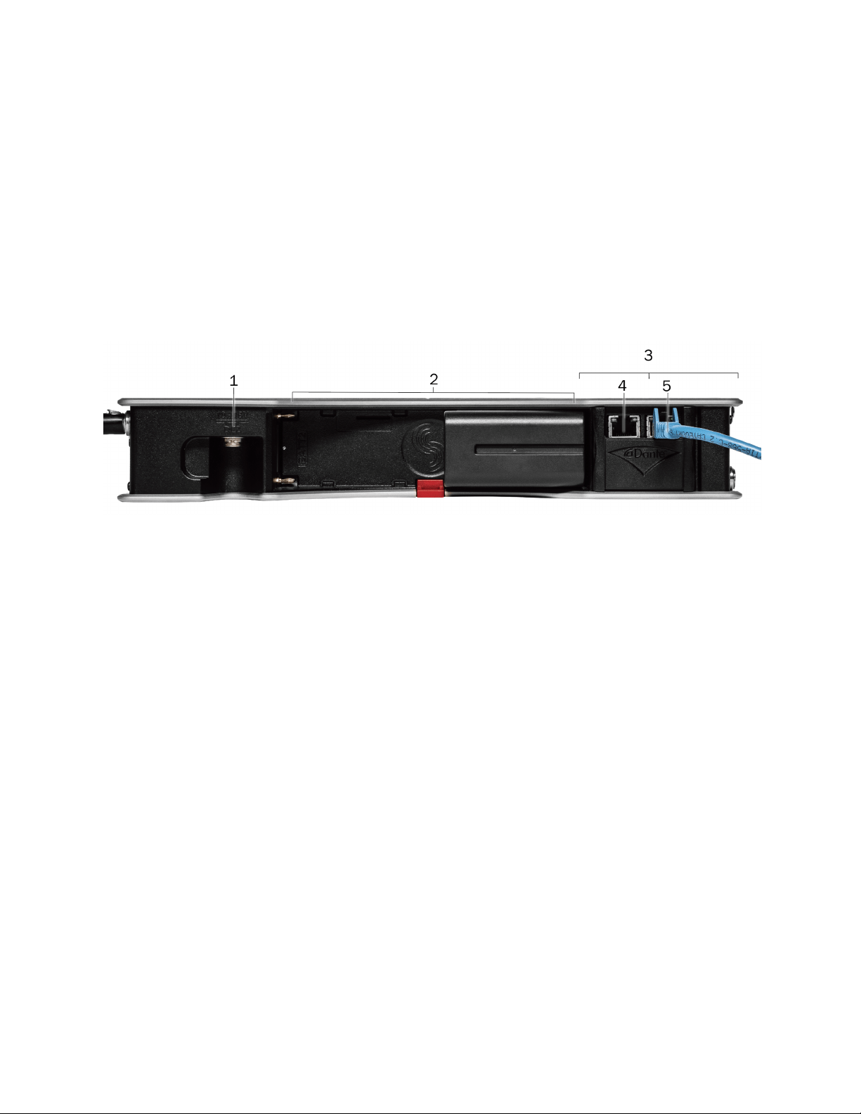
Rear Panel
1: 10-18V DC2 TA4 Jack
Accepts DC voltages from 10–18 V for powering. [pin-1- GND, pin-2- Smart Battery DATA, pin-3- Smart Battery CLOCK, pin-4-
+10-18 VDC]
2: Battery 1, Battery 2 Docking
Sony L-Mount type batteries may be used. When connected to an external DC source via DC1 or DC2 the L-Mount batteries can be
charged if enabled in the Power menu.
3: Dante/Ethernet RJ45 Jacks
Two-1 GbE ports serving as connections to Dante audio networks or to Frame.io servers. The Dante interface provides 32 inputs
and 32 outputs simultaneously with sampling rates up to 96 kHz. Routing is defined through the Channel Source and Output menus.
Dante Controller app on Mac/PC (from Audinate) is needed to route and use Dante.
Allows connection to Frame.io and setup. See Frame.io for more details.
Do not connect both Primary and Secondary Ethernet ports to the same network.
4: Primary Ethernet Port
5: Secondary Ethernet Port
Scorpio User Guide 8
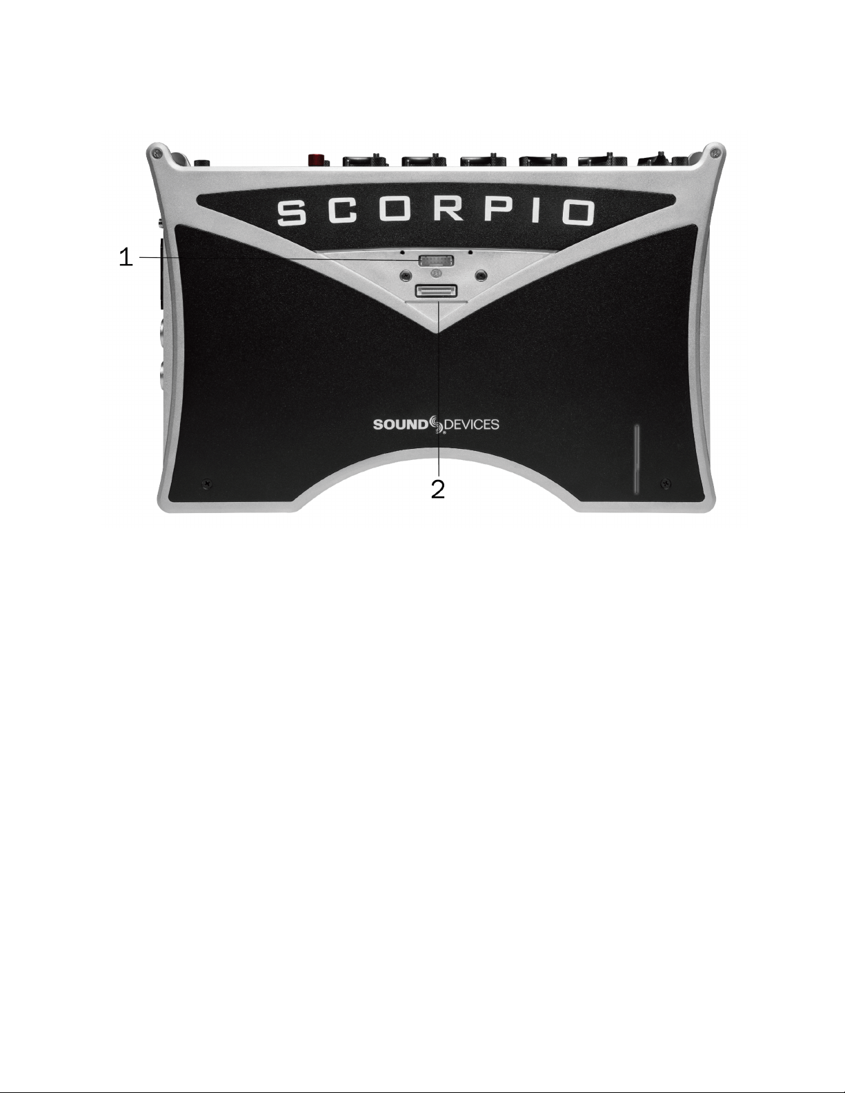
Top Panel
1: SL-6 Port Multipin Molex Ribbon connector used for connecting SL-6. Remove all power on Scorpio and the SL-6 before
connecting.
The SL-Riser is required to connect the SL-6 to Scorpio.
2: Expansion Port
Used for connecting the A20-Nexus multichannel receiver, SL-2 Dual SuperSlot Wireless Module, or XL-AES 8 Channel AES3 Input
Expander
Scorpio User Guide 9
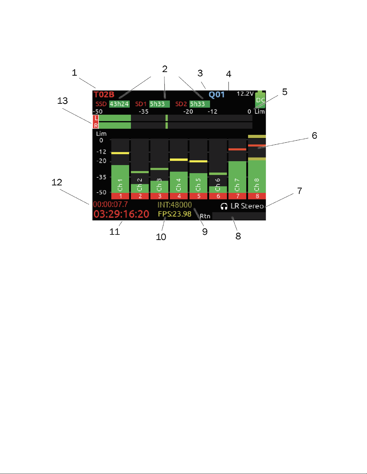
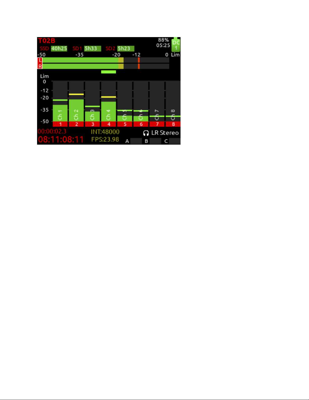
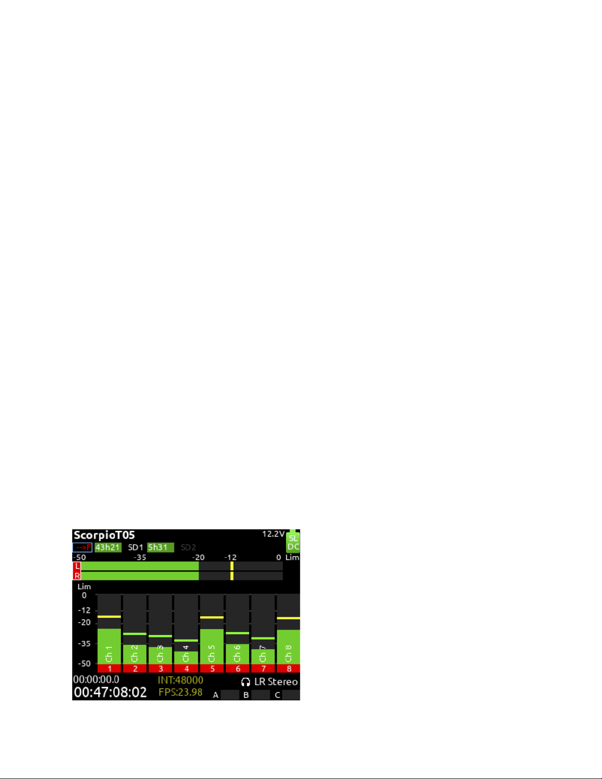
Home Screen
1: Current Take Name
Shows the filename of the currently-selected take.
2: SSD, SD1, SD2
Indicates the amount of recording time available based on current track count, sample rate, and media routing. The internal SSD
drive has a capacity of 256 GB.
3: Q-Mark
Indicates Q-mark number.
4: Smart Battery Telemetry
Indicates time remaining and percent remaining of Smart Battery life. Other power sources will show voltage.
5: Power Icon
Indicates approximate voltage condition and current power source being used. When Smart Batteries are in use the remaining
percentage and time is displayed.
6: Individual Channel Meters with Arm Indication
Indicates the peak and VU audio levels of the individual channel. May be Pre- or Post- fade depending on Channel to ISO routing.
7: Selected Headphone Preset
Indicates the currently-selected headphone preset.
8: Metering for Returns A, B and C
Indicates audio level for the returns.
Scorpio User Guide 10

9 & 10: Sample Rate / Frame Rate/ Temporary Level Display
1. Indicates current sample rate.
2. Indicates current frame rate.
3. Temporarily indicates fader level of last moved fader (red text box).
4. Temporarily indicates trim level of last moved trim (green text box).
5. Temporarily indicates bus level of last adjusted bus fader (light blue text box).
6. Temporarily indicates output level of last adjusted out gain (white text box).
7. Temporarily indicates EQ freq and gain of last adjusted EQ (blue text box when EQ is On, orange text box when EQ is off
or band is bypassed).
11: Timecode
Indicates current SMPTE timecode value.
12: File Elapsed/ Remaining Time
Indicates in Hours:Minutes:Seconds:1/10ths the elapsed time of the current file. During playback, displays the elapsed and
remaining time in hours, minutes and seconds.
13: LR Mix Bus Meters with Arm/Disarm Indication
Indicates the peak and VU audio levels of the L/R mix. The L and R indicators turn red to indicate that the tracks are armed for
record.
Scorpio User Guide 11
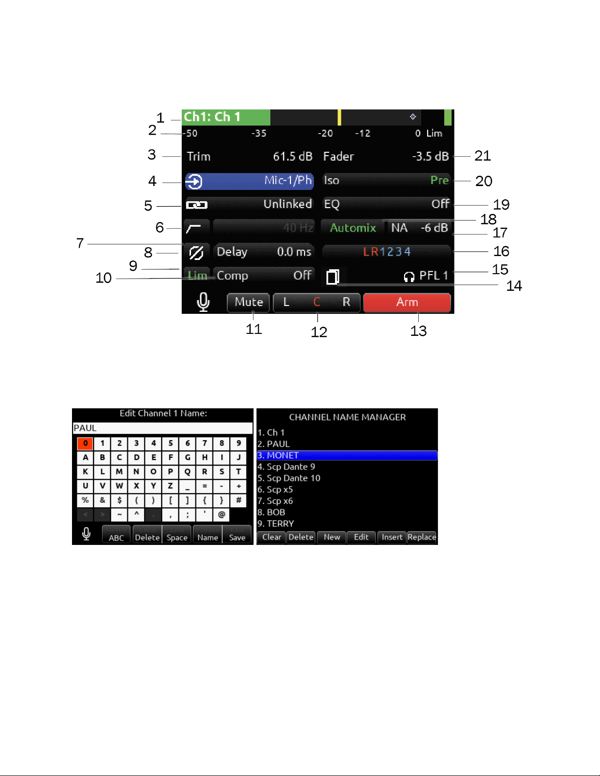
Channel Screen
1: Channel Designation and User-Defined Name
Indicates the mixer channel designation and the user-defined channel name. Both are overlaid onto the channel audio meter. When
in a Channel Screen, hold the PFL Switch for about 1 second to enter the virtual keyboard and enter a user-defined name for the
channel. From this virtual keyboard, select Name on the Rtn toggle to access the Channel Name Manager from which you can
create, edit, delete, insert, and replace channel names.
2: Channel Meter View
Indicates the audio level of the channel. Metering follows ISO Routing selection, Pre- or Post-fade.
3: Channel Trim Value
Indicates the gain of the channel trim control. The gain range depends on the type of input selected.
● Mic: -inf, +12 to +76 dB
● Line: -inf, -14 to +50 dB
● Dante: -inf, -20 to +50 dB
● SL-2 (Rx): -inf, -20 to +50 dB
● SL-2 (AES): -inf, -20 to +50 dB
● SL-6: -inf, -20 to +50 dB
● SL-2/SL-6 (A20 Transmitter GainForward): -inf, 0 to +60 dB
● A20-Nexus: -inf, -20 to +50 dB
● A20-Nexus (A20 Transmitter GainForward): -inf, 0 to +60 dB
Scorpio User Guide 12
● AES3: -inf, -20 to +50 dB
● AES42: -inf, 0 to +70 dB
● XL-AES: -inf, -20 to +50 dB
● Returns: -inf, -20 to +30 dB
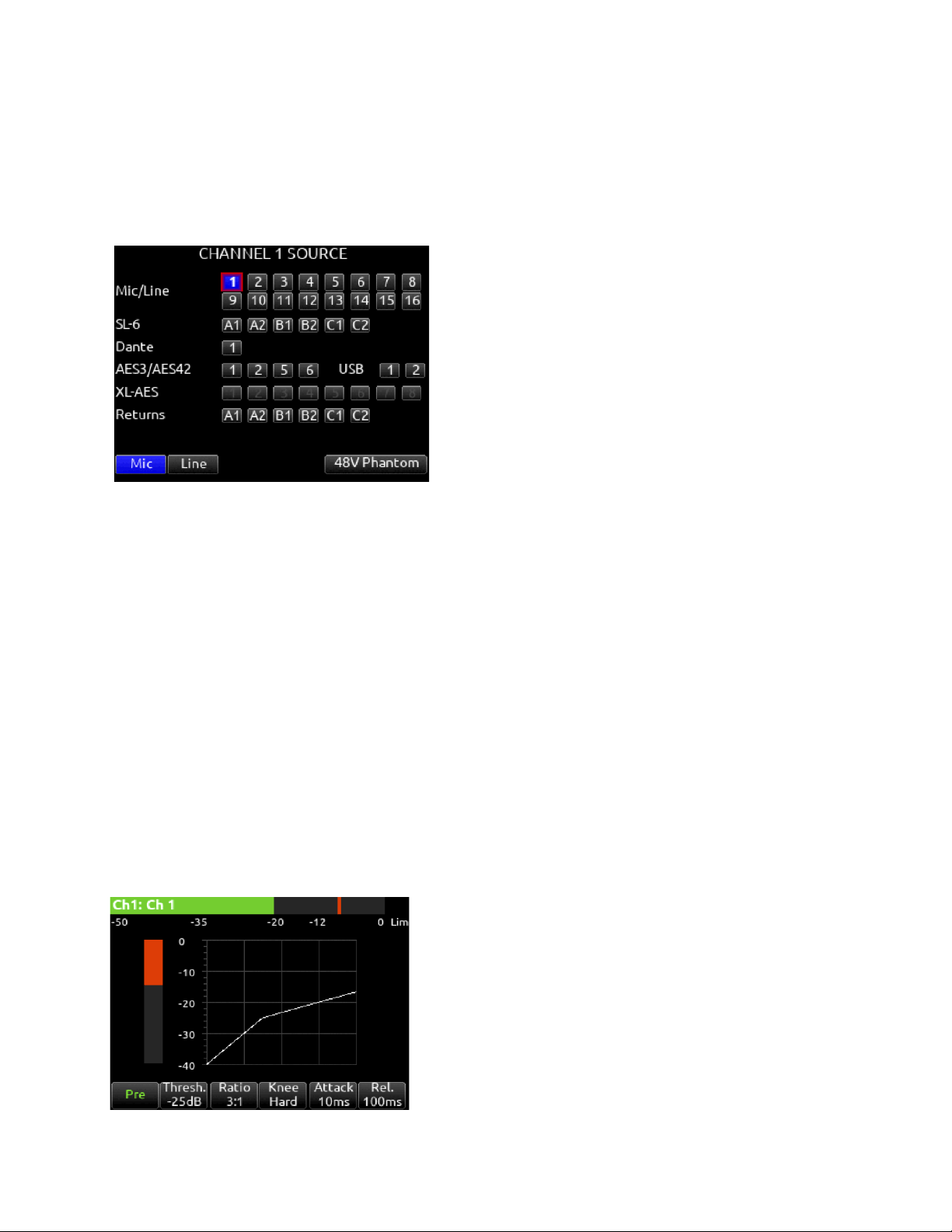
4: Channel Input Source Selection
Indicates which physical audio input source is feeding the channel. Sources can be changed during stop or record.
5: Channel Linking
Indicates the current linking status. The linking options are Unlinked, adjacent channels (eg. 1,2) and adjacent channels Mid Side
(eg. 1-2MS). Linked parameters are: trims, faders, HPF, EQ, delay, limiter, mute, ISO, Bus Send 1 and Bus Send 2. Stereo panning
is 1 to L and 2 to R. MS spread can be adjusted either in the odd channel’s MS balance field by holding */** and rotating Select or by
using the even channel’s front panel trim pot. See Channel Setup menu. When unlinking from a stereo or MS pair, odd and even
channel pans get set back to center.
6: HPF (High Pass Filter)
Indicates on/off status where green icon and white value = ”On” and gray icon and value = “Off”. The HPF frequency is variable in 10
Hz steps from 10 Hz to 320 Hz.
7: Polarity Reverse
Indicates polarity status. Green icon = polarity reversed, white icon = polarity normal.
8: Channel Input Delay
Indicates input delay time. The input delay is continuously-variable in milliseconds from 0-50 ms.
9: Channel Limiter
Indicates on/off status of channel limiter.
10: Channel Compressor
Compression, pre- or post-fade is available on channels 1-32. Select to enter Channel Compressor screen. Note: Compression can
also be applied to Buses.
Mic Toggle
Selects Compression state and insert location. Indicates where the
compression is inserted into the audio chain. Pre-fade or Pos-tfade [Off*,
Pre, Post]. Compression applies to bus sends only when applied Prefade.
Tone Toggle
Selects threshold [0 to -40 dB]
* Toggle
Selects Ratio. [1.0:1 to 20:1 in 0.1 steps]
** Toggle
Selects Knee. [Hard, Soft]
Rtn Toggle
Selects Attack time [1 to 200 ms in 1 ms steps].
FAV Toggle Selects Release time [50 to 200 ms in 1 ms steps, 200 to 1000
ms in 10 ms steps]
Scorpio User Guide 13
11: Mute
Indicates mute status of channel. Blue icon = muted. Toggle mute on/off with the “Tone” switch.
12: L C R Select
Indicates the stereo pan position of the channel’s contribution to the L/R mix. Orange = selected. Use the */** switch to select. Hold
*/** switch and rotate select knob for continuous panning positioning. Alternatively, press and hold Select knob, then use */** switch
to pan continuously. Rotating the select knob while holding */** will change the balance of Mid, Center and Side when two channels
are MS linked.
13: Arm
Toggle the Rtn/Fav switch.
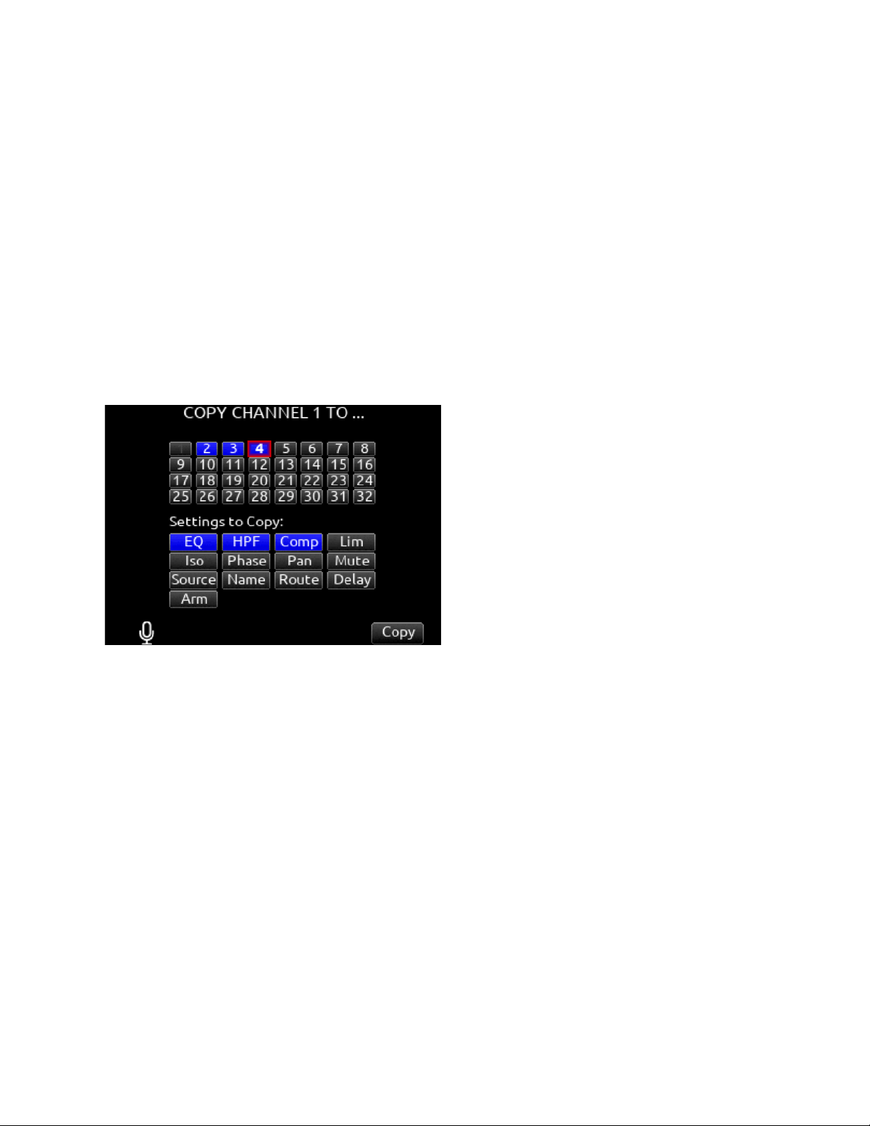
14: Channel Copy
Channel Copy provides a mechanism for quickly copying multiple settings from one channel to other channels.
Select the Channel Copy icon to access the Copy Channel screen.
Choose which channels to apply the copied settings. Multiple destination channels can be selected. Then choose which settings to
copy. Select any combination from EQ, HPF, Compressor, Limiter, Iso, Phase, Pan, Mute, Source, Name, Routing, Delay, and Arm.
To copy, toggle the Fav switch.
Note: When copying from channels 17-32 EQ, Phase, and Delay are grayed out and not selectable. These functions are not
available on Channels 17-32.
15: HP Preset
Pressing the HP knob toggles between HP preset and PFL. Can be used to listen to channel panning while viewing the Channel
Screen by setting the HP Preset to LR Stereo.
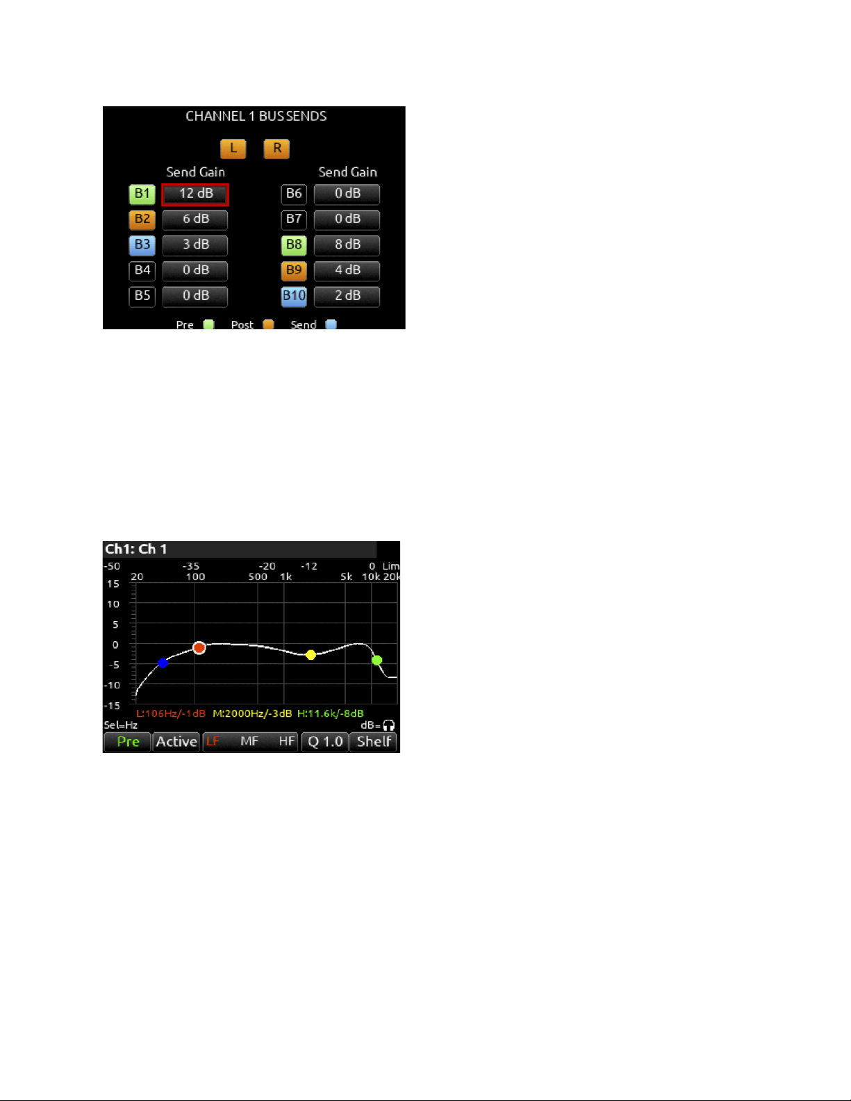
16: Channel to Bus Routing
Determines to which bus or buses the channel audio will be sent. When a channel is routed to a bus as a Send (bus box highlighted
blue), the Send Gain value is used. When a channel is sent Pre (green) or Post (orange), the Send Gain value is ignored.
Scorpio User Guide 14
17: Noise Suppression (NA or NX)
Indicates whether the channel is selected for Sound Devices NoiseAssist (NA) or CEDAR sdnx (NX) and how much is applied. Field
is grayed out when the Noise Suppression is disabled. White ‘--’ (dashes) when Noise Suppression is enabled but channel not
selected; white ‘dB’ value when channel is selected. NoiseAssist and CEDAR sdnx are optional paid Plugins.
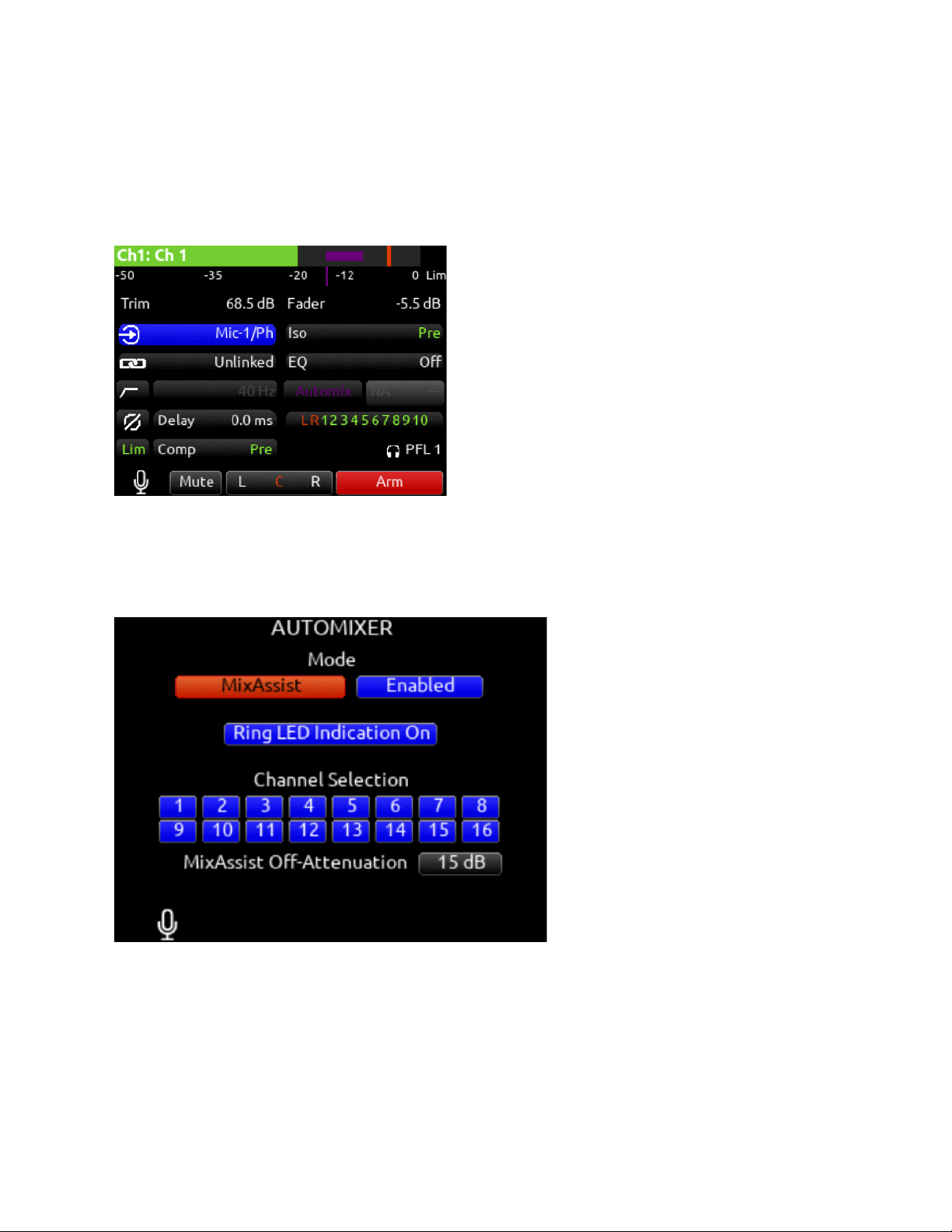
18: Automix
Indicates whether the channel is selected for automixing.
Purple text = On and white text = Off.
19: Channel EQ
3-band parametric EQ, pre- or post-fade is available on channels 1-16. Select to enter the Channel EQ screen which displays the
EQ settings as an EQ curve. The channel’s HPF setting is also displayed as a blue circle here.
Mic Toggle
Selects EQ state and insert location. Indicates where the EQ is
inserted into the audio chain. Pre-fade or Post-fade [Off*, Pre, Post].
EQ will apply to bus sends only when applied Pre-fade.
Tone Toggle
Selects EQ band mode [Bypass*, Active]
*/** Toggle
Selects EQ band. Use Select encoder to adjust frequency and HP
encoder to adjust gain of the filter. [LF*, MF, HF] All filters are
sweepable from 20 Hz to 20 kHz.
RTN Toggle
Selects Q (bandwidth) of selected band [0.5 - 10] (use Sel or HP
knob to adjust).
FAV Toggle
Toggles filter type of LF and HF band [Peak, Shelf*].
20: ISO (Channel->ISO) Routing
Indicates where the isolated track’s audio is tapped from in the audio chain. Pre-fade or Post-fade
21. Channel Fader Value
Indicates the level of the channel fader control, continuously-variable from -inf to +16dB.
Scorpio User Guide 15
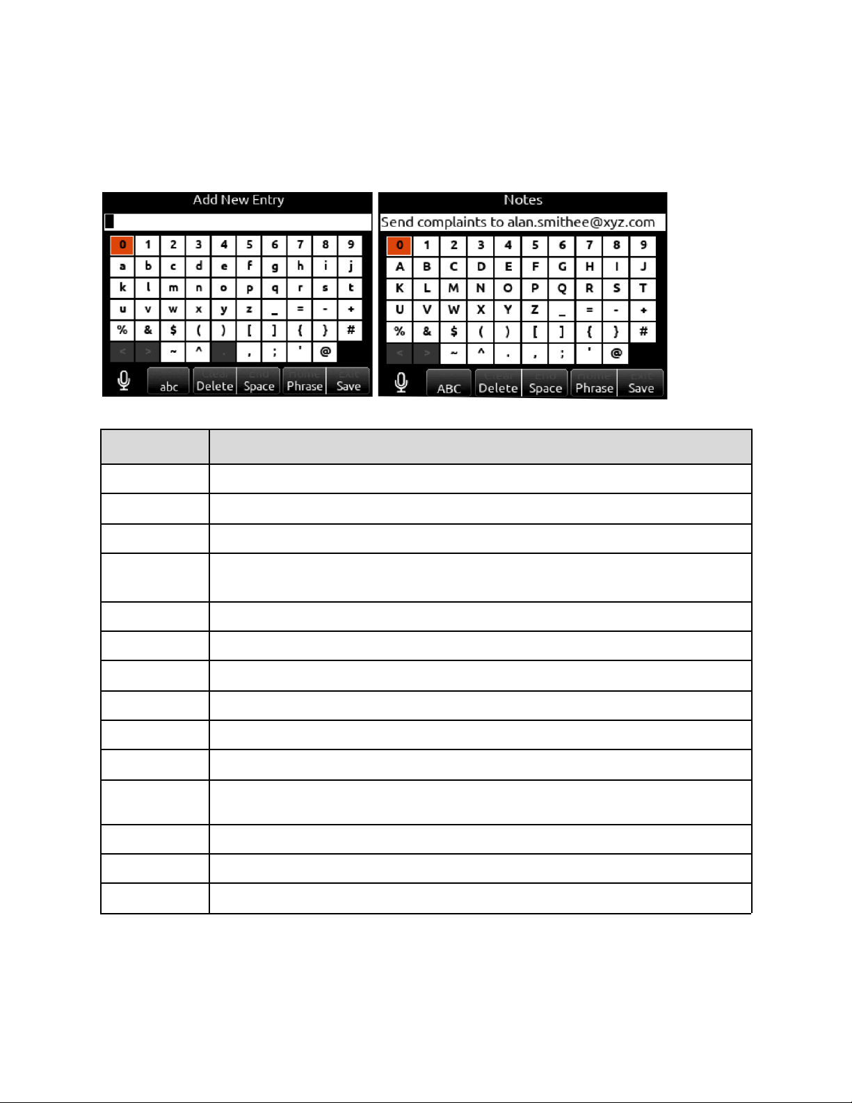
Virtual Keyboard
The virtual keyboard appears when alphanumeric text is to be entered or selected for editing. For example, Channel Names, Scene
Names, Notes etc. The table below defines how the various toggle actions below the LCD are used with the virtual keyboard.
Action
Function
Rotate HP
Scrolls orange highlight through the keyboard characters.
Press HP
Inserts the highlighted character in text field.
‘abc’ switch
Quick flick toggles between A-Z and a-z in keyboard.
Hold ‘abc’ switch
Momentary selection of other case.
Delete
Deletes character to the left of flashing cursor.
Hold Delete
Repeatedly deletes characters to the left of flashing cursor.
Space
Inserts space at the flashing cursor position.
Hold Space
Repeatedly inserts spaces.
Save switch
Saves text and exits screen.
Rotate Select
Moves the cursor to the left or right in the text field.
Quick Press Select
Switches to the Shifted functions: Clear, End, Home, Exit. When shifted functions are active, their text
changes to white and the non-shifted functions change to gray.
Clear
Clears text from the text edit field.
End/Home
Moves cursor to end/start of text.
Exit
Exits screen without saving text edits.
Scorpio User Guide 16
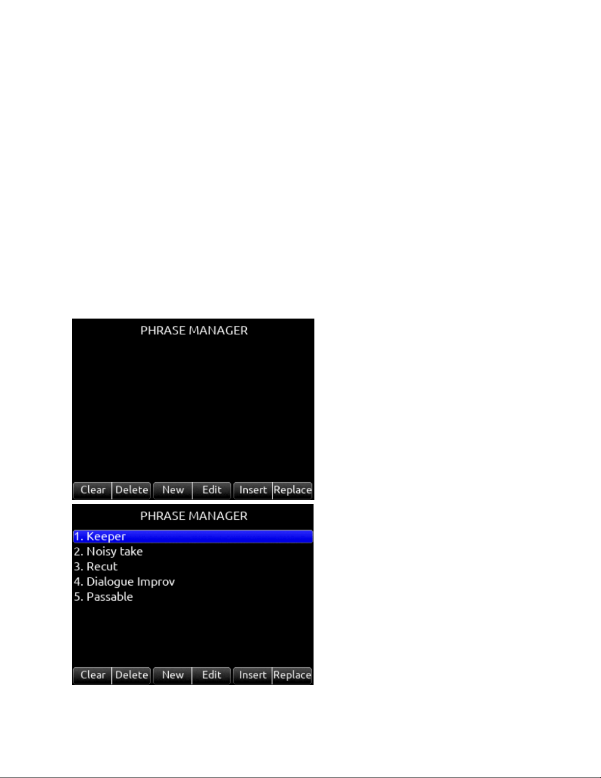
Phrase Manager
Phrases entered in the Phrase Manager are available in all virtual keyboard text editing screens such as scene names, channel
names, notes, SD Card volume label etc.
Clear
Clears all phrases.
Delete
Deletes selected phrases.
New
Creates a new phrase.
Edit
Edits the selected phrase.
Insert
Inserts selected phrase into text.
Replace
Replaces text with current selected phrase.
Scorpio User Guide 17
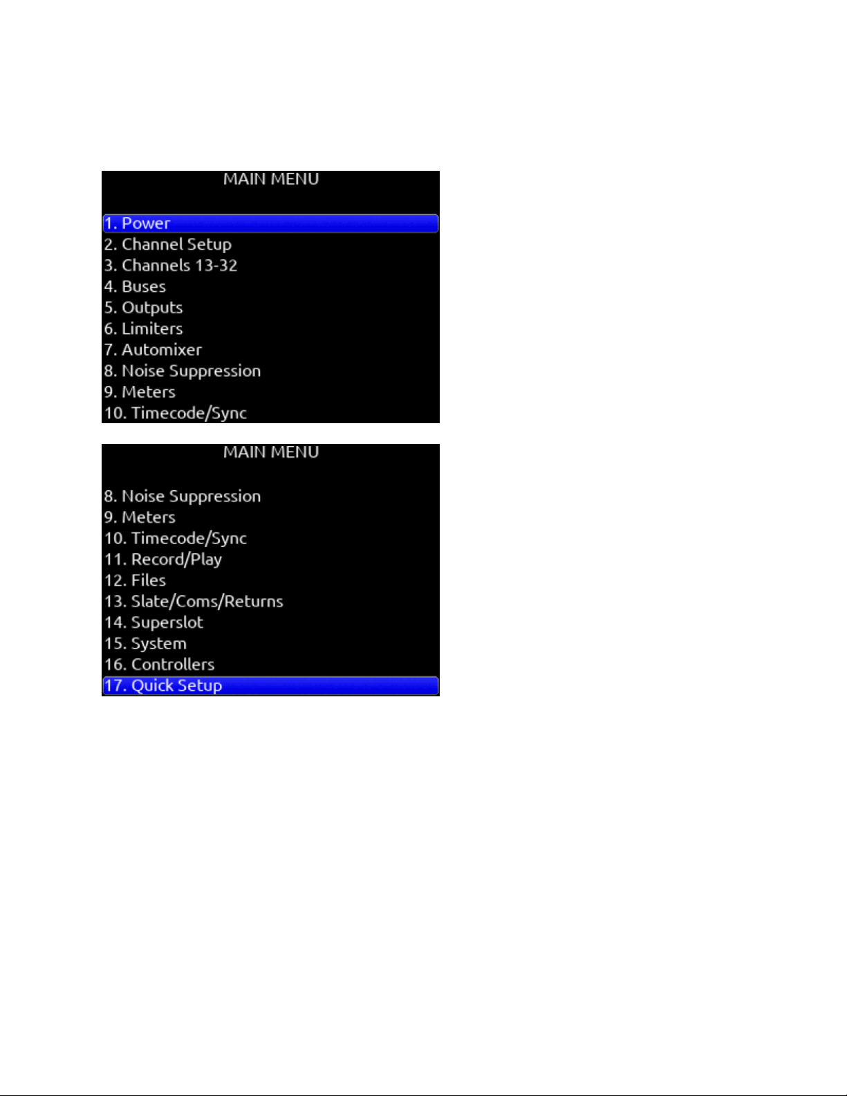
Menus
Main Menu
Scorpio User Guide 18
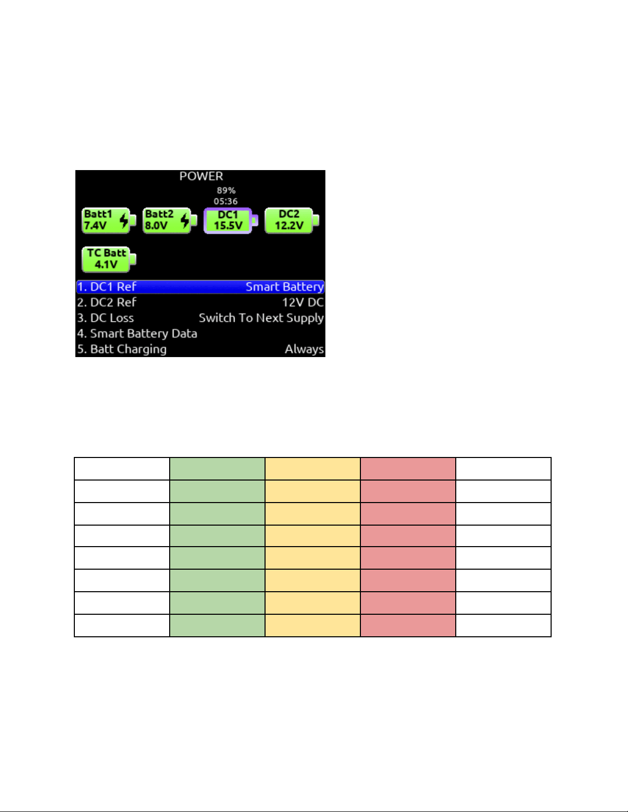
Power
Allows configuration of various power settings.
Power Source Icons
(Batt1, Batt2, DC1, DC2, TC Batt,) Indicates the power condition of each power source. [Green = normal, yellow = below normal, red
= warning]
DC1 Ref
Allows proper power level indicator calibration based upon the type of DC power source used. [12V DC*, 14 V Li-Ion, 12 V Lead
Acid, Full Range (10-18 V), Smart Battery], NP1 Data.
DC2 Ref
Allows proper power level indicator calibration based upon the type of DC power source used. [12V DC*, 14 V Li-Ion, 12 V Lead
Acid, Full Range (10-18 V), Smart Battery], NP1 Data.
Power Source
Good
Marginal
Low
Shutdown
DC 12 V
12.50 V
11.00 V
10.10 V
9.50 V
Li-Ion 14 V
16.30 V
13.90 V
13.60 V
11.50 V
Lead Acid 12 V
14.00 V
11.50 V
10.30 V
10.20 V
Full Range
18.00 V
12.00 V
10.20 V
9.50 V
Smart Battery
16.00 V
13.50 V
12.60 V
10.75 V
NP1 Data Battery
16.30 V
13.90 V
13.60 V
11.50 V
Li-Ion L-Mounts
8.30 V
7.10 V
6.95 V
6.80 V
DC Loss
Selects how the unit should operate when DC power is lost. [Switch to Next Supply*, Turn Off]
Scorpio User Guide 19

Smart Battery Data
Displays Time Remaining, Percent Remaining, Cycle Count, and Temperature of Smart Battery 1 and Smart Battery 2.
Note: This menu is only displayed when a Smart Battery is connected
Batt Charging
Selects Sony L-Mount battery charging mode when connected to an external DC source. [Disabled, When Power On, When Power
Off, Always] Battery charging not available when the SL-6 is connected.
USB-A Charge Port
Allows charging of compatible external USB devices such as Android tablets. Set to 500 mA or 1.5 A
Scorpio User Guide 20
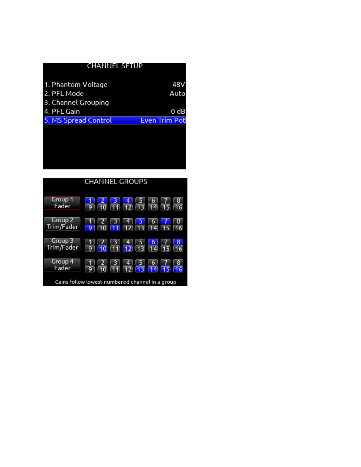
Channel Setup
1. Phantom Voltage
Selects phantom power voltage for all inputs. [12 V, 48 V*]
2. PFL Mode
Selects the source of the PFL feed. [Auto* Pre-fade, Post-fade] Auto = pre-fade if channel is routed to ISO track pre-fade,
post-fade if channel is routed to the ISO track post-fade.
3. Channel Grouping
Channel Groups can be set to Off, Mute/Arm, Trim/Fader, or Fader. Groups allow the lowest channel number in the group
to act as master control.
● Off: Group disabled. Groups that are Off retain their channel routings but settings and levels are independent
per channel. This allows for quick enabling or disabling of a group without losing group routings.
● Mute/Arm: Only channel mutes and arms are grouped.
● Trim/Fader: Trim, fader, record arming, limiters, and mutes are grouped. Trims can only be grouped when all
channels of the group share the same gain range. Gain ranges depend on input type routed to a channel. See
Channel Screen>Channel Trim Value for more detail.
● Fader: Fader groups act just like Trim/Fader groups but trims remain independent per channel.
Four channel groups are possible; channels grouped can only be assigned to one group.
A. Group 1 [1-16]
B. Group 2 [1-16]
Scorpio User Guide 21

C. Group 3 [1-16]
D. Group 4 [1-16]
4. PFL Gain
A preset amount of gain that is applied to any channel(s) with active PFL.
5. MS Spread Control
Selects how the MS spread is controlled when a pair of channels are MS-linked. [PFL Screen, Even Trim Pot]. PFL
Screen = MS spread controlled by holding the odd channel’s PFL screen */** toggle and rotating Select. Even Trim Pot =
MS spread controlled by rotating the front panel’s even trim pot.
6. Use Wireless Names (only when A20-Nexus is docked)
When A20-Nexus is attached using the A20-QuickDock accessory, the Use Wireless Names option enables the
A20-Nexus transmitter/receiver channel names to be rippled directly to the 8-Series channels that they are routed to. This
feature is also available for the SL-2 and SL-6. See SL-2 and SL-6 Options for more information.
Scorpio User Guide 22

Channels 13-32
Provides access to channel screens 13-32.
Access is also possible by using the */** + PFL switch shortcuts:
* + PFL 1-12 = Ch 13-24
** + PFL 1-8 = Ch 25-32
Trims, Faders and PFL’s for channel’s 13 and 14 can be controlled by a combination of the toggle switches beneath the LCD and
the Select and HP Knobs. Setup in the System>Toggle Switch Action menu. See the Toggle Switch Action section for information on
which of the following options are available for each toggle switch:
Ch 13 or 14 Trim/PFL (Latch)
Flick toggle then rotate Select to adjust ch 13 or 14 trim. Gain values are displayed in the Home Screen sample rate field. Press
Select to PFL. Flick toggle to cancel mode.
Ch 13 or 14 Fader/PFL (Latch)
Flick toggle then rotate Select to adjust ch 13 or 14 fader. Gain values are displayed in the Home Screen sample rate field. Flick
toggle to cancel mode
Ch 13 Trim/PFL (Moment)
Hold toggle then rotate Select to adjust ch 13 trim. Gain values are displayed in the Home Screen sample rate field. Press Select to
PFL
Ch 14 Trim/PFL (Moment)
Hold toggle then rotate HP to adjust ch 14 trim. Gain values are displayed in the Home Screen sample rate field. Press HP to PFL
Ch 13 Fader/PFL (Moment)
Hold toggle then rotate Select to adjust ch 13 fader. Gain values are displayed in the Home Screen sample rate field. Press Select to
PFL
Ch 14 Fader/PFL
(Moment) Hold toggle then rotate HP to adjust ch 14 fader. Gain values are displayed in the Home Screen sample rate field. Press
HP to PFL
Scorpio User Guide 23
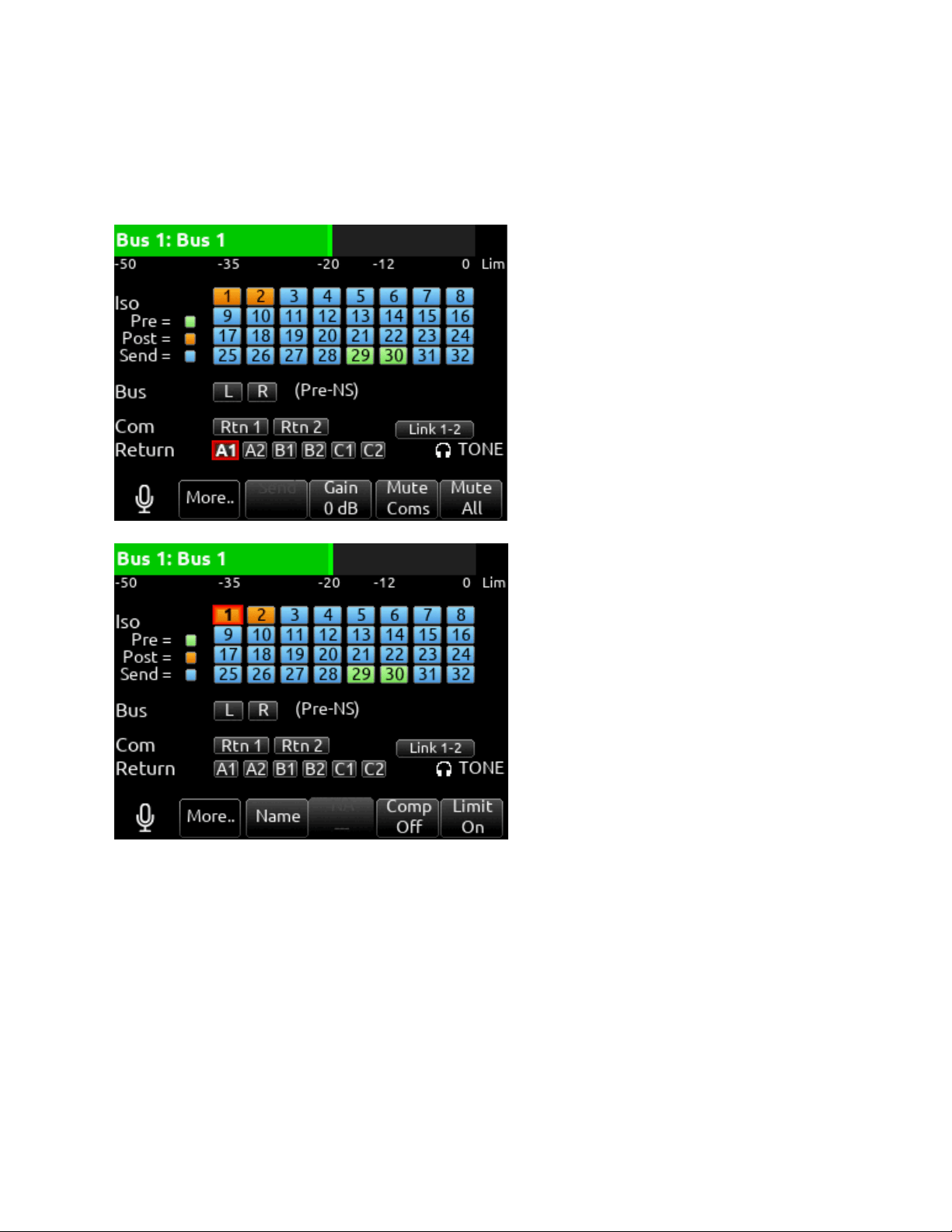
Buses
Selects routing for Buses L,R and 1-10. Access buses via Menu > Buses or by holding Select and toggling a PFL switch.
When a bus screen is entered, that bus is solo’d by default in both HP L and HP R. If the bus is linked, the odd bus will be heard in
HP L and the even bus in HP R. Toggle between Solo and the current HP preset by pressing the HP encoder.
1. Bus Meter
Audio level meter for the selected bus.
2. Link *-*
Selects linking for two even-to-odd numbered adjacent buses. Links bus Gain, bus limiters, Mute Coms, and Mute All
functions.
3. ISO
Any ISO channel contributes to Bus mix. [Green fill in text box = Pre-fade, Orange fill in text box = Post-fade, Light Blue fill
in text box = Send gain] Send adjusts the Iso channel send gain to the bus when the selected Iso channel is routed as a
‘Send’ to that bus (light blue fill in text box). When the selected Iso channel is set to ‘Send’ (light blue fill), enter the Send
field with the * toggle then adjust send gain by rotating the HP encoder.
Scorpio User Guide 24

Tip: Recorded ISOs can be played back via buses. This is useful for playing back alternate ISO mixes on set. By routing
the ISOs as bus sends instead of pre or post-fader, you can adjust the ISO mix on playback. Use Buses B3-B10 for this
purpose since Bus L, R, B1, and B2 can be recorded and are reserved for playing back their own recorded audio.
4. Bus
L,R, 1,2 (available on buses 3-10).
5. Com
Rtn 1, Rtn 2 (not available on L,R buses).
6. Return
[A1, A2, B1, B2, C1, C2 (not available on L,R buses).
7. Slate
Activates the slate mic. Slate mic will follow settings from Slate/Coms/Returns menu.
8. More..
Select to bring up a second page of Bus toggle switch functions including:
Name: Select to name the bus
NoiseAssist (NA) or Cedar SDNX (NX) In Bus 1-10 screens, use ** toggle to adjust the amount of NoiseAssist
or CEDAR sdnx applied to the selected bus.
Bus Compressor (Comp): Select Rtn toggle to set compressor parameters for the selected bus. Available bus
compressor parameters:
Mic Toggle: Selects Compression On or Off.
Tone: Selects threshold [0 to -40 dB]
* Toggle: Selects Ratio. [1.0:1 to 20:1 in 0.1 steps]
**Toggle: Selects Knee. [Hard, Soft]
RTN Toggle: Selects Attack time [1 to 200 ms in 1ms steps]
FAV Toggle: Selects Release time [50 to 200 ms in 1 ms steps, 200 to 1000 ms in 10 ms steps]
Limiter control.
Bus Limiter (Limit): Select Fav toggle to toggle Limiter On or Off.
9. Send (Bus Send on Fader)
Channel Bus Sends in Bus screens. Use the Sel knob to navigate through the Bus send routing. When an ISO set to Send
(highlighted in light blue) is selected, activate the * toggle then rotate the HP knob to adjust the gain of the ISO sent to the
bus. Toggle the * switch again to exit Bus Sends on Faders.
10. NoiseAssist (NA) or Cedar SDNX (NX) In Bus L and R screens, use ** toggle to adjust the amount of NoiseAssist or
CEDAR sdnx applied to the selected bus.
11. Gain
Use ** toggle to select and adjust selected bus gain in 1 dB increments. [Off-16 dB]
12. Mute Coms
Selects muting of Coms 1, 2 sends and returns.
13. Mute All
Indicates mute status of bus. Blue icon = muted. Toggle Mute All On/Off with the “Fav” toggle.
Scorpio User Guide 25
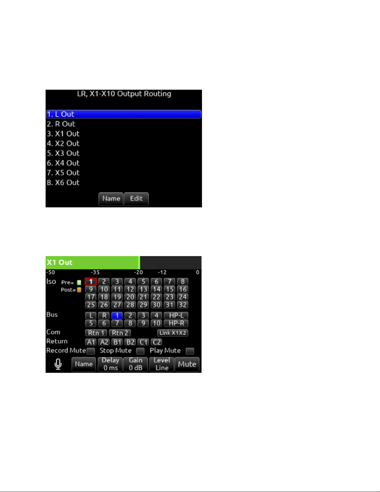
Outputs
LR, X1-X10 Output Routing
Selects routing for L,R and X1-X10 outputs [L Out, R Out, X1, X2, X3, X4, X5, X6, X7, X8, X9 and X10 Out]
Note: Only a single source can be routed to an Output. If multiple sources need to be routed, use a Bus.
Name Opens a keyboard for naming the selected Output. Output names appear in output meter views when a meter view preset
has Track Names enabled.
Edit
Enters the Output screen. The bus can also be entered by pressing the Sel or HP encoder.
1. ISO
Selected source will contribute to the Output. (Green = Pre-fade, orange = Post-fade [1-32])
2. Bus
[L,R, 1-10, HP-L, HP-R]
3. Com
[Rtn 1, Rtn 2]
4. Return
[A1, A2, B1, B2, C1, C2]
Scorpio User Guide 26

5. Record Mute
Selects automatic muting of the output when in Record mode. [Off*, On]. When an output is auto-muted, you can still
mute/unmute manually.
6. Stop Mute
Selects automatic muting of the output when in Stop mode. [Off*, On]. When an output is auto-muted, you can still
mute/unmute manually.
7. Play Mute
Selects automatic muting of the output when in Play mode. [Off*, On]. When an output is auto-muted, you can still
mute/unmute manually.
8. Delay
The output delay is continuously-variable in milliseconds from 0-500 ms.
9. Gain
Selects amount of attenuation applied to the output. Toggle the ** to select [0 dB to -50 dB and -inf]
10. Level
Selects output level type. [Line, -10, Mic, AES]
AES is available for L and R Outputs, AES is not available on X1-X10. See AES Output for more information.
11. Mute
Indicates mute status of output (Orange = muted) Toggle Mute On/Off with the “Fav” toggle.
12. Link
*-* Selects linking for two even-to-odd numbered adjacent outputs. Links gain, mutes, and delays.
10-Pin A Out Routing
Selects routing for 10-Pin A outputs.
1. A1
Selects mix bus for A1 output [L,R, 1-10].
2. A2
Selects mix bus for A2 output [L,R, 1-10].
3. Record Mute
Selects automatic muting of the output when in Record mode. [Off*, On]. When an output is auto-muted, you can still
mute/unmute manually.
4. Stop Mute
Selects automatic muting of the output when in Stop mode. [Off*, On]. When an output is auto-muted, you can still
mute/unmute manually.
5. Play Mute
Selects automatic muting of the output when in Play mode. [Off*, On]. When an output is auto-muted, you can still
mute/unmute manually.
6. Delay
The output delay is continuously-variable in milliseconds from 0-500 ms.
7. Gain
Selects amount of attenuation applied to the output. Toggle the ** to select [0 dB to -50 dB and -inf].
8. Level
Selects output level type for A1 and A2. [Line, -10, Mic, AES] Selecting AES changes A1 and A2 from analog to AES
Outputs 5-8 and accesses the AES Output Routing menu. See AES Output for more information.
9. Mute
Indicates mute status of bus (Blue icon = muted) Toggle Mute On/Off with the “Fav” toggle
10-Pin C Level
Selects the output level type [Line*, -10, Mic].
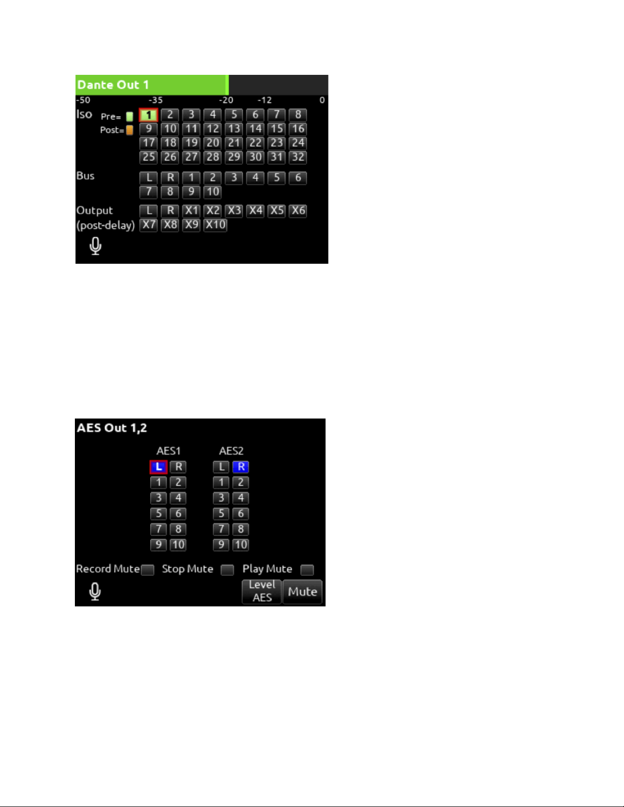
DANTE
Selects routing for Dante output.
1. ISO
Any source selected will be routed to the selected Dante output. (Green fill in text box = Pre-fade, Orange fill in text box =
Post-fade [1-32])
2. Bus
[L,R, 1-10]
3. Output
All sources are selected post-delay. [L,R, X1-X8]
Scorpio User Guide 27
USB
Selects routing for USB outputs.
1. Iso
Any source selected will be routed to the selected USB output. (Green fill in text box = Pre-fade, Orange fill in text box =
Post-fade [1-32])
2. Bus
[L,R, 1-10]
3. Output
All sources are selected post-delay. [L,R, X1-X10]
AES Output
Scorpio User Guide 28
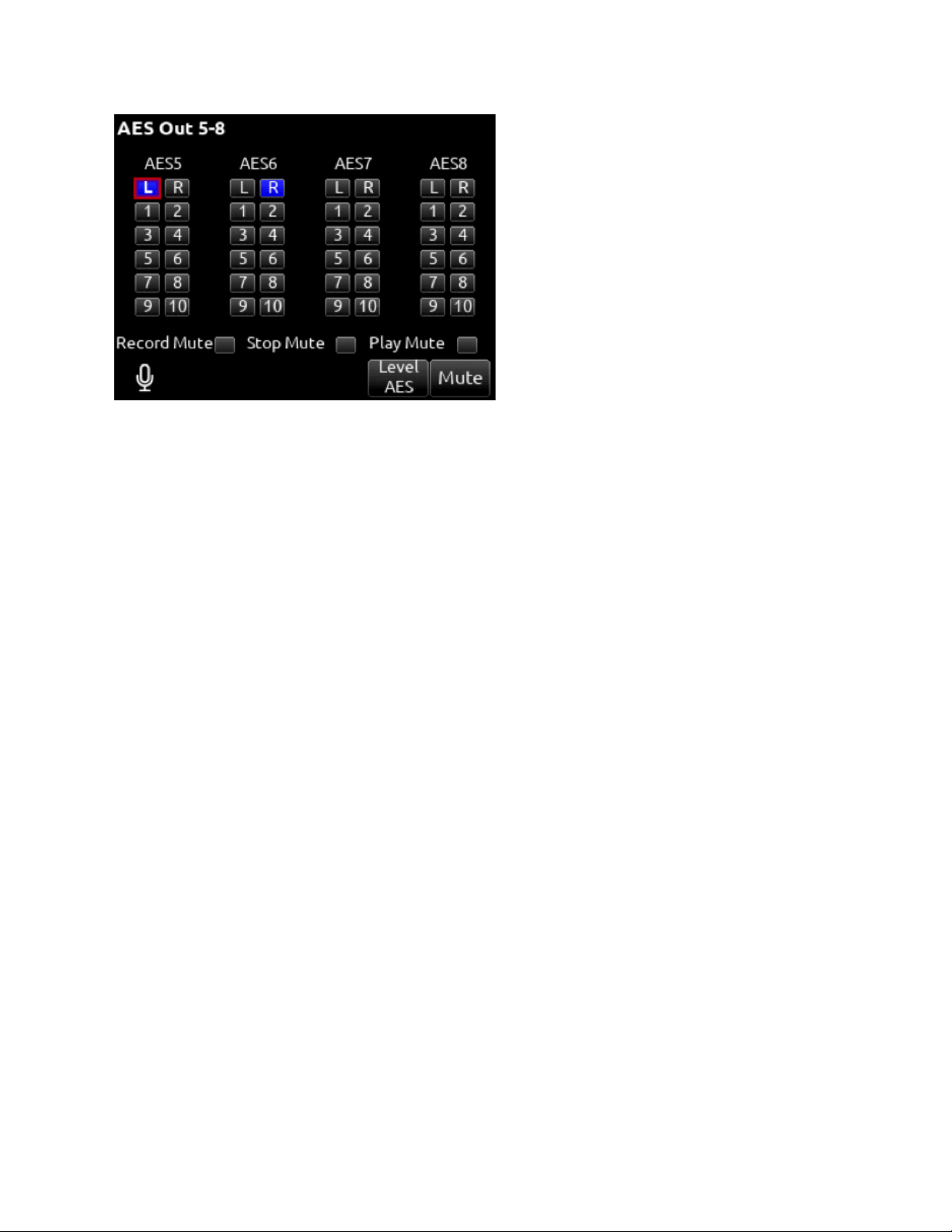
Selecting AES as the Level for L, R, or 10-Pin A Outputs accesses the AES Output Routing menus. L Output is used to output AES
1 and 2. R Output is used to output AES 3 and 4. 10-PIn A is used to output AES 5-8.
From the AES Output Routing menus, route any bus to any AES Output using the Select knob.
Change Level back to Line, -10, or Mic to cancel AES Output and return to the L, R, or 10-Pin A Output menus.
10-Pin A and C
Mates with Hirose RM15TPD-10P(71) connector.
Outputs are Active Balanced, output level is selectable in the menus between Line, -10, or Mic level.
For unbalanced connections, XLR connectors should be wired pin 1 ground, pin 3 floating, pin 2 positive.
Balanced AES3 Outputs on 10-Pin A connector, 110 ohm, 2
V p-p, AES3 and S/PDIF compatible with RCA adapter.
1 – L (+) output (AES 5 on 10-Pin A)
2 – L (–) output (AES 6 on 10-Pin A)
3 – R (+) output (AES 7 on 10-Pin A)
4 – R (–) output (AES 8 on 10-Pin A)
5 – R (+) return A
6 – n/c
7 – L (+) return A
8 – n/c
9 – ground
10 – ground
Scorpio User Guide 29

HP Presets
Selects the list of headphone presets available and allows for editing and creation.
Function
Description
Name
Displays virtual keyboard and allows for naming of the headphone preset.
Edit
Allows selection of routed sources to both HP Left and HP Right. Select HP LEFT or RIGHT and then select
desired source.
i. ISO- Any source selected will be routed to the selected HP output. Green = Pre-fade, orange = Post-fade. [1-16]
ii. Bus- [L,R, 1-8]
iii. Com- [Rtn]
iv. Return- [A1, A2, B1, B2]
Mono
Selects monophonic monitoring of selected HP-L/HP-R sources.
MS
Applies MS decoding to the selected HP-L/HP-R preset sources.
Unlist
De-selects a preset in the list preventing it from being listed in the HP Preset menu (press HP knob on Home
Screen).
List
Selects a preset in the list allowing it to be listed in the HP Preset menu (press HP knob on Home Screen).
Fav
Selects a favorite preset. The name turns green when selected. The “Fav” switch recalls this HP preset when in
the Home Screen.
Scorpio User Guide 30
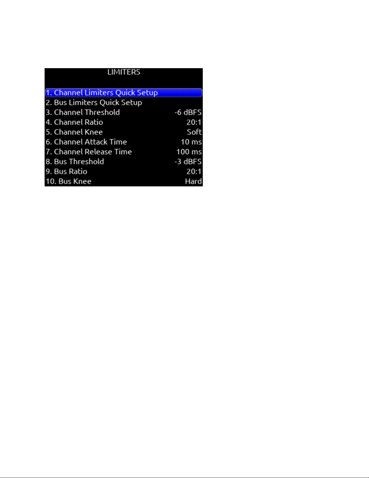
Limiters
Channel Limiters Quick Setup
Selects the channel limiters on/off status globally. [All On*, All Off]
Bus Limiters Quick Setup
Selects the bus limiters on/off status globally. [All On*, All Off]
Channel Threshold
Selects the threshold at which the channel limiters activate. -6 dBFS* [-2 to -12 dBFS]
Channel Ratio
Selects the ratio of the limiter. [Inf:1, 10:1, 12:1, 14:1, 16:1, 18:1, 20:1*]
Channel Knee
Selects the channel limiter Knee. [Hard, Soft]
Channel Attack
Selects the channel limiter attack time [1*-200 ms]
Channel Release Time
Selects the release time of the limiters in 10 ms increments. 100 ms* [50-1000 ms]
Bus Threshold
Selects the threshold at which the bus limiters activate. -3 dBFS* [-2 to -12 dBFS]
Channel Threshold
Selects the threshold at which the channel limiters activate. -6 dBFS* [-2 to -12 dBFS]
Bus ratio
Selects the ratio of the limiter. [Inf:1, 10:1, 12:1, 14:1, 16:1, 18:1, 20:1*]
Bus Knee
Selects the bus limiter Knee. [Hard, Soft]
Bus Attack
Selects the bus limiter attack
Bus Release Time
Scorpio User Guide 31

Selects the release time of the limiters in 10 ms increments. 100 ms* [50-1000 ms]
Bus Threshold
Selects the threshold at which the bus limiters activate. -3 dBFS* [-2 to -12 dBFS]
Scorpio User Guide 32
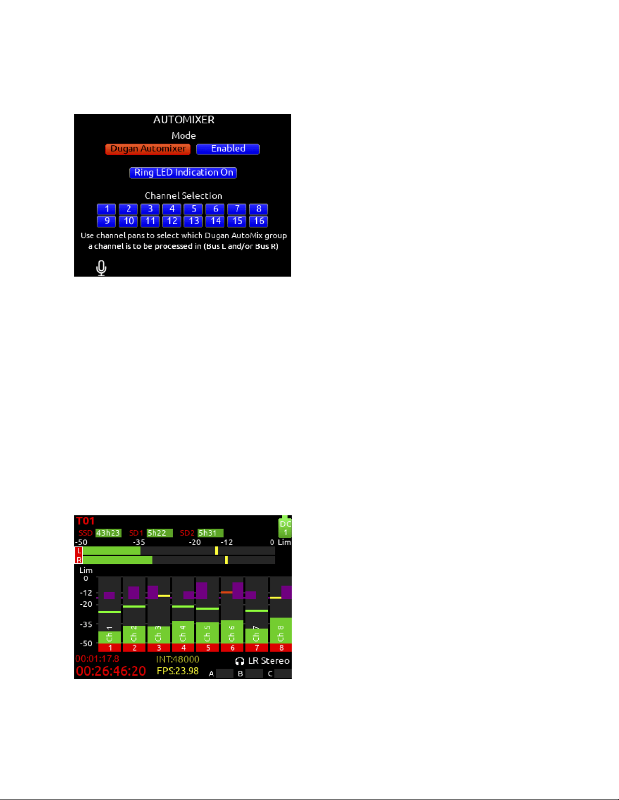
Automixer
Selects the Automixing mode and the channels included in the automixer group(s).
Mode Selects the Mode of Automix [MixAssist, Dugan Automixer] and whether it is disabled* or enabled.
Note: Set a toggle shortcut or mapped controller button to enable/disable the selected automixer mode to allow you to quickly
compare the effect of the automixer being on or off.
RING LED INDICATION Set to On to display automix meter levels on the ring LEDs. Set to Off if you prefer to only see automix
levels in the LCD meter views.
Channel Selection Selects which of channels 1-16 are included into the automix group(s). A channel can also be selected for
automix from channel screens 1-16. Enter a channel screen 1-16 then use the
Select encoder to scroll to and toggle the Automix on or off for that channel. Purple text is On, white text is Off.
Note: Automixer is only available with sample rates of 47952, 48000, and 48048 Hz.
Note: If a channel is enabled for automixing, it sets post-fade routing of that channel to Bus L and R in the Channel Bus Sends menu
and the Bus L and R routing menus. Channels can still be unrouted or routed pre-fade to Bus L and R but note that automixing only
applies to post-fade channels.
Dugan Automixer Mode
Dugan gain display bars are overlaid on top of the channel signal meters. The top 15 dB of the meter scale is shared between
Dugan gain display bars and audio signal metering. Dugan gain display bars range from 0 dB (at the top, aligned with 0 dBFS, no
attenuation) to -15 dB (max attenuation). The -15 dB value is indicated by a purple horizontal graticule mark near the top of a
channel’s signal meter when that channel is enabled for Dugan in Menu>Automixer.
There are two independent Dugan processing groups, Bus L and Bus
R. Channels 1-16 can be routed to Bus L, Bus R, both equally (Center), or both unequally (L or R pan increments) by using a
channel’s pan control.
Scorpio User Guide 33
To show which Dugan group the channel is in, the Dugan gain display bar is left-aligned for fully L, right-aligned for fully R and
center-aligned for any other pan value. When a channel is routed to both Dugan groups (Bus L and R), the center-aligned gain
display bar shows the least attenuated value.
The Channel Screen shows the Dugan gain display bar overlaid within the horizontal channel meter. The Dugan gain display scale
and indication is the same as in the main meter screen.
The ring LEDs for ch 1-12 show Dugan gain for ch 1-12. The ring LEDs begin to glow purple at 15 dB attenuation and increase in
intensity at
0 dB attenuation.
MixAssist Mode
MixAssist Off-Attenuation
Sets the amount of attenuation applied to inactive input channels. Range: 6 dB to 40 dB. Default: 15 dB.
When a channel is active (not attenuated), it’s ring LED (channels 1-12 only) and LCD meter view channel indication illuminate
green.
There are two independent MixAssist processing groups, Bus L and Bus R. Channels 1-16 can be routed to Bus L, Bus R, both
equally (Center), or both unequally (L or R pan increments) by using a channel’s pan control.
Scorpio User Guide 34
Scorpio User Guide 35
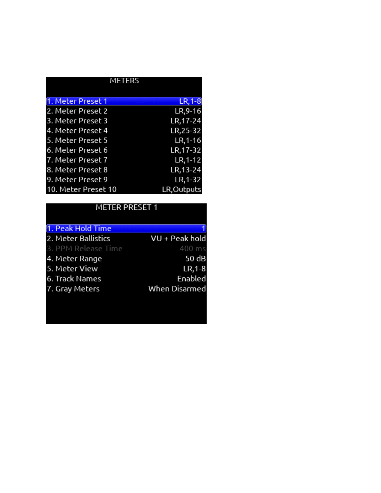
Meters
Meter Presets 1-12
Peak Hold Time
Selects the peak hold time for the meter
preset. [Off, 1*-5s., Infinity]
Meter Ballistics
Selects the ballistics for the meter preset.
VU: The meter bar ballistics emulate the 300 ms attack and 300 ms release times of a VU meter. VU meter ballistics correspond
closely to how the human ear perceives loudness. This provides a good visual indication of how loud a signal will be.
VU + Peak Hold: Same as the VU setting but with the addition of a peak hold segment. See Peak Hold Time above.
PPM: The meter bar ballistics have instantaneous attack time and slow release time. Ideal for monitoring actual signal peaks. The
release time can be set using the PPM Release Time setting.
PPM + Peak Hold: Same as the PPM setting but with the addition of a peak hold segment. See Peak Hold Time above.
PPM Release Time
Selects the Release Time for the PPM meter ballistics. [400 ms* to 1600 ms in 200 ms steps]
Scorpio User Guide 36
Meter Range
Selects the range of the meters from bottom to top of scale. [50 dB*, 40 dB, 20 dB]. When in a meter view, press and hold Meter
while rotating HP knob to adjust the meter scale on the fly.
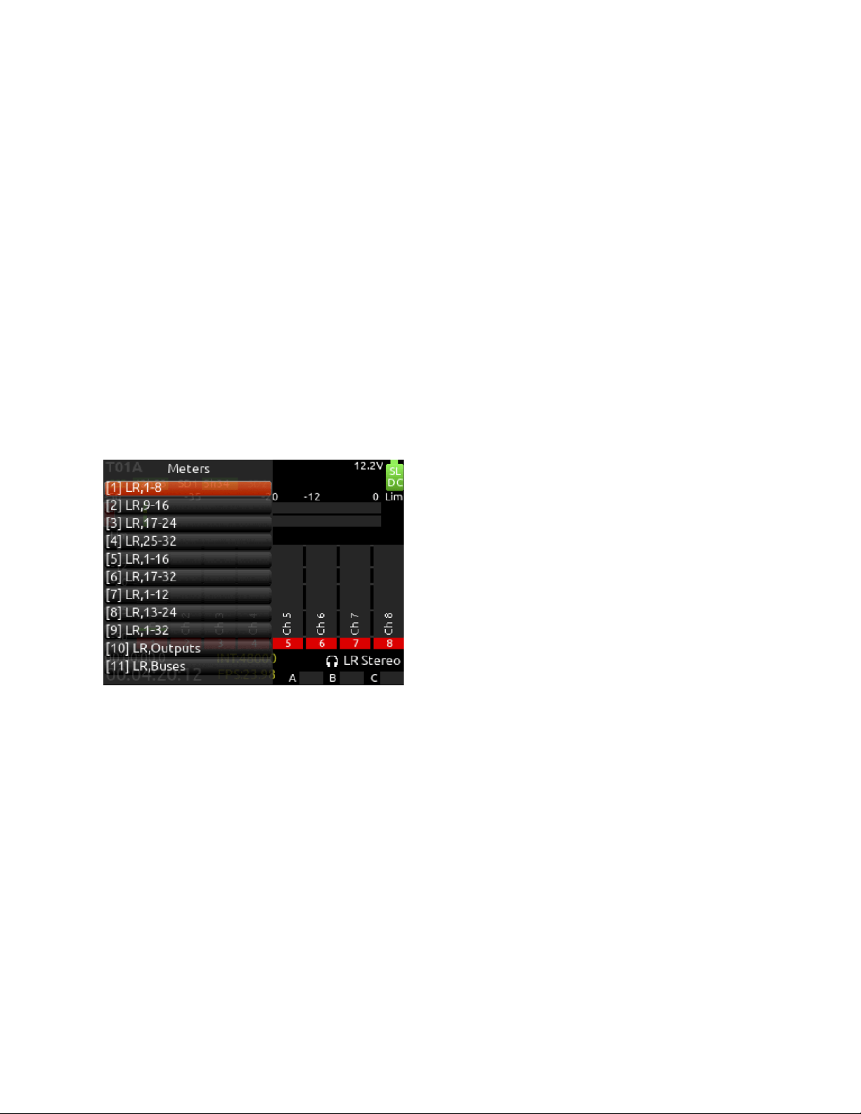
Meter View
Selects the meters to be viewed in the current preset. [LR,1-8*, LR,9-16, LR,17-24, LR,25-32, LR,1-16, LR,17-32,
LR,1-12, LR,13-24, LR,1-32, 1-8 (Horizontal), 9-16 (Horizontal),
17-24 (Horizontal), 25-32 (Horizontal), LR,1-8 (Horizontal), LR,9-16
(Horizontal), LR,17-24 (Horizontal), LR,25-32 (Horizontal), LR,Outputs,
LR,Buses, LR,Returns, LR,Buses (Horizontal), LR,Outputs (Horizontal, LR,1-8,B1-2,X1-2, LR Out,B1-4,X1-4, LR
Out,B1-4,X1-4(Horizontal), LR,1-3 (Horizontal)]
Track Names
Selects whether track name, output name, and bus name are displayed in the meter preset. [Enabled*, Disabled]
Gray Meters
Grays out meters in the 8-series meter views when record disarmed. [When disarmed*,Off]
SL-2 Receiver Overview
Selects the Peak Hold Time and Meter range for the SL-2 Receiver Overview audio level meters. Ballistics and PPM release time
are taken from the last selected Meter Preset. Menu not available unless an SL-2 is connected.
Meter View Menu Shortcuts
When in LR, Outputs and LR, Buses Meter Views
Turn the Select knob to scroll to an output or bus. Pressing the Select knob acts as a shortcut to that outputs or bus routing screen.
Scorpio User Guide 37
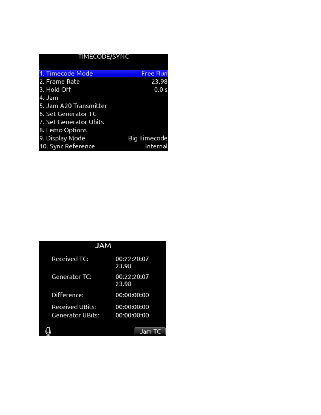
Timecode
Timecode Mode
Selects the timecode mode of operation. [Off, Record Run, Free Run*, Free Run Auto Mute, Free Run Jam Once, 24 Hour Run
(ToD), 24 Hour Run Auto Mute, Ext TC, Ext TC - Auto Record, Ext TC Continuous, Ext TC Cont. - Auto Record]
Frame Rate
Selects the current frame rate. [23.98*, 24, 25, 29.97 ND, 29.97 DF, 30 ND, 30 DF]
Hold Off
Selects the amount of time incoming timecode needs to be valid prior to entering record when in auto-record mode. [0.0*-8.0
seconds in steps of 0.1 sec]
Jam
Indicates the Received TC, Generator TC and the calculated difference between the two. Received and Generator UBits are shown.
Jamming to external TC and UBits is supported. Jam TC- Toggle Rtn/Fav switch to jam to external TC.
Scorpio User Guide 38
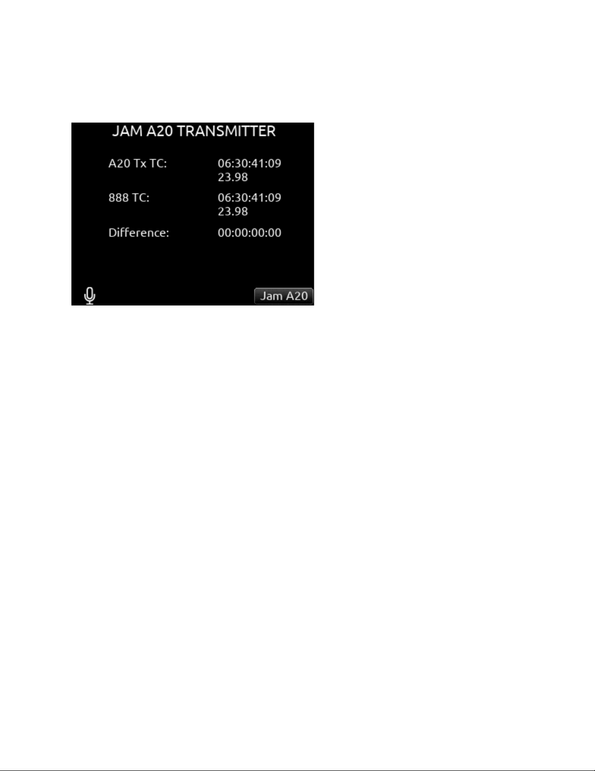
Jam A20 Transmitter
This menu is normally grayed out. It is only available when an A20 transmitter is connected via USB-A to the Scorpio. Displays the
timecode and frame rate of Scorpio and A20 transmitter along with the calculated difference.
Toggle the Jam A20- Rtn/Fav switch to jam the A20 transmitter. (Picture shows screen for 8-series model 888)
Set Generator TC
Provides the ability to start rolling internal TC from a manually entered value in the format of HH:MM:SS:ff.
Set Generator U-Bits
Provides UBits manual and automatic
entry. [U=User entered UU:UU:UU:UU*, mm:dd:yy:UU, dd:mm:yy:UU,
Use External] Use Rtn/Fav toggle to exit.
Lemo Options
Selects pin-2 and pin-5 options for TC Lemo connector.
A. Pin-2 - [TC In*, WCK In, WCK Out]
B. Pin-5 - [TC Out, WCK Out]
Display Mode Selects whether to display Big Timecode or Big A-Time.
Sync Reference
Selects current sync reference for all transport
modes (record, stop and play). [Internal*, Word Clock, LTC In, AES 1,2 (XLR 1), AES 5,6 (XLR 6)] Ring LEDs flash yellow while
locking to the selected sync reference. Once locked, the LEDs will stop flashing. Should the LEDs flash indefinitely, the selected
sync reference has not been detected. Locking can take up to 30 seconds.
Note: Expansion port accessory AES inputs cannot be used as a sync reference source.
Holding TC While Powered Down When a TA4 DC power source is not connected, the Scorpio holds timecode accurately for four
hours before resetting, provided the internal timecode backup battery is charged. When a TA4 external battery is connected,
timecode will continue counting indefinitely until the external battery drains. To prevent the external battery from draining, set
Timecode Mode to Off.
The internal timecode battery charges when:
1. The Scorpio is on and powered by L-Mount batteries, TA4 DC In, or the SL-6.
2. The Scorpio is off, power is connected to one of the TA4 DC Ins, and the Power>Batt Charging option is set to Always or
When Power is Off.
Note: The timecode battery does not charge when the unit is Off and power is connected to the SL-6.
Scorpio User Guide 39
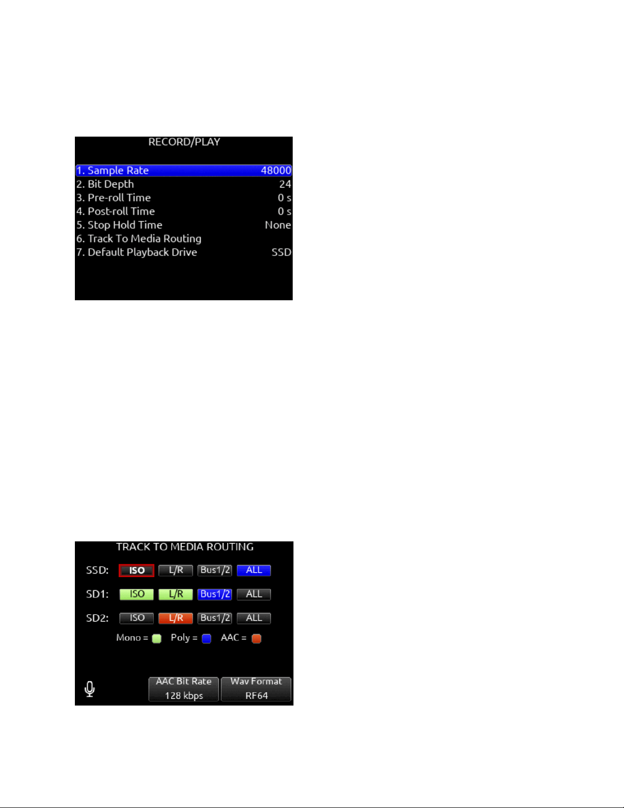
Record/Play
Sample Rate
Selects the current sample rate. [44100, 47952, 48000*, 48048, 96000, 192000 Hz]
Bit Depth
Selects the current bit depth. [16, 24*]
Pre-roll Time
Selects the amount of Pre-roll recording. Adjustable in 1 second increments. *0 s [0-10 s]
Post-roll Time
Selects the amount of Post-roll recording. Adjustable in 1 second increments. [0-10 s] If a recording is stopped prematurely, press
record within the post-roll time. The machine will continue to record into the original file. Useful for when directors call ‘cut’
prematurely. During the post-roll period, the transport joystick ring LED shows orange. Pressing stop again during the post-roll
period cancels the post-roll and stops recording.
Stop Hold Time
Selects how long Stop must be pressed before record or playback stops. Useful for preventing accidental termination of recording or
playback.
Track to Media Menu
Selects the sources for each recording media as well as the type of file recorded. Tracks may be routed to media to be recorded as
AAC (LR or Bus 1,2 only), WAV Mono, or WAV Poly files. (Green text box= WAV Mono file, Blue text box= WAV Poly file, Orange
text box = AAC)
Scorpio User Guide 40

Select whether Mono or Poly WAV files are recorded in standard BWF or RF64 format using the Rtn/Fav toggle. BWF WAV files
seamlessly auto-split to a new file when the max BWF 4GB file size is reached. Split files can be joined in any DAW. RF64 WAV files
have a much higher maximum file size and do not require auto-splitting.
Note: Most DAWs support WAV RF64. Some NLEs do not. It is recommended to check NLE compatibility before using RF64.
Also: 8-Series Q-marks are not supported when RF64 is selected.
Tracks L/R and Bus1/2 can be recorded as AAC audio files. (Orange text box). AAC files are ideal for transcription.
Select the AAC Bit Rate using the */** toggle switches. [32, 64, 128, 192, 256 kbps]
Select the WAV Format using the Rtn/Fav toggle switches. RF64 allows for WAV files larger than 4 GB.
A. SSD- [ISO, L/R, Bus1/2, ALL]
B. SD1- [ISO, L/R, Bus1/2, ALL]
C. SD2- [ISO, L/R, Bus1/2, ALL]
To differentiate between the ISO and L/R mix poly files:
“ISO” is appended to the end of the ISO poly file’s filename.
“LR” is appended to the end of an L/R poly file’s filename.
“B1B2” is appended to the end of a Bus 1/2 poly file’s filename.
* Up to 36 track recording supported with sampling rates 44.1- 96 kHz. Up to 18 track recording at 192 kHz.
**Monophonic file recording up to 48.048 kHz.
*** AAC file format when recording at 48 kHz.
Default Playback Drive
Selects the drive for playback. [SSD, SD1, SD2]
Playback Take/File From Take/File List
Enter the take or file list and select a take or file with either knob. Pressing play will playback the selected take or file.
Arming/Disarming During Recording
All channels can be armed/disarmed while recording. This creates a seamless split to a new file or files. The split takes will be
suffixed with an incrementing alphabetic character. I.e. A, B, C…
Auto-Split
Takes that are auto-split due to the 4 GB limit of BWF format are also suffixed using the same A, B, C...incrementation.
Record Split
Takes that are split when pressing record during recording increment the file’s take number.
False Takes
Press HP + << to false take the last recording. This moves the last take to the FALSETAKES folder at the root of each drive and
decrements the take number in preparation for the next take.
Scorpio User Guide 41

Q-marks
Use Q-marks, (also known as cue marks) to mark points of interest within a recording. Q-marks can be added and deleted during
recording, playback, pause, or scrub mode when viewing the Home screen. Once added, they can easily be located to during
playback on the 8-Series. Q-marks are also embedded in the WAV file and can be read by audio editing applications such as
Reaper and Adobe Audition.
Note: Q-marks are only supported when using the BWF WAV format, not the RF64 WAV format.
Note: Q-marks in auto-split files (due to BWF 4GB max size) are not supported.
To add a Q-mark, hold Select and press >>.
The Q-mark number is displayed in blue at the top of the meter view to the right of the take name. Each time a new Q-mark is
added, the Q-mark number is incremented. (Q01, Q02, Q03)
To delete a Q-mark, hold Select and press <<.
Q-marks can also be added and deleted using Toggle Switch Action shortcuts, Midi mapped buttons, and USB Keyboard buttons ‘Q’
and ‘delete’.
Locating to Q-marks during playback, pause, or scrub:
To locate to the next Q-mark, press >>. If there is no next Q-mark, pressing >> will locate to the end of the take and will pause
playback. To locate to the previous Q-mark, press <<. If there is no previous Q-mark, pressing << will locate to the beginning of the
take.
Tip: To check the last few seconds or minutes of a long take, Press >> after the last Q-mark has been passed. This will pause
playback at the end of the take. Then rewind or reverse scrub to the point of interest and press play.
Scorpio User Guide 42
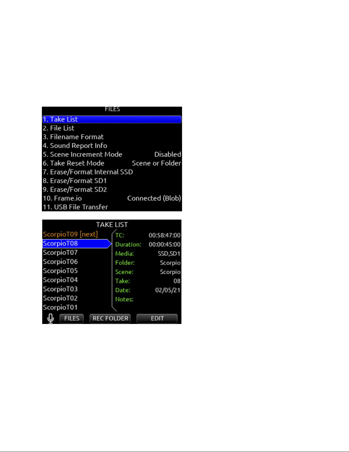
Files
Take List
Enters the Take List. The Take List shows a running list of recorded takes in chronological order with most recent at the top. Various
details of each take are indicated on the right side of the display: TC (timecode), Duration, Media, Folder, Scene, Take, Date, and
Notes. From this list, takes may be selected for metadata editing by using the Rtn/Fav toggle or pressing the HP knob to access the
Take Edit Menu.
Press Menu + HP knob as a shortcut to the Take List. Highlight any take in the Take List, then press play to play it back.
Record Folder
Record Folders are containers for storing recorded audio files and sound reports. They can be nested up to three levels deep. Set a
record folder as ‘current’ to determine where audio files and sound reports are stored.
Record folders are unified across all three media (SSD, SD1, SD2) - any actions taken on a record folder (NEW, SET CURRENT,
Delete Folder, Create Sound Report) affect that record folder on all three media.
To select an existing record folder or to create a new record folder, go to the Take List and use the */** toggles to access the REC
FOLDER menu. By default, the RECORD FOLDER menu displays a list of record folders at root. Navigate to nested folders by
highlighting a record folder and pressing the Sel/HP knob. To navigate back up the folder hierarchy, press Menu or select “\..” at the
top of the folder list. The screen’s title identifies the folder path.
Scorpio User Guide 43
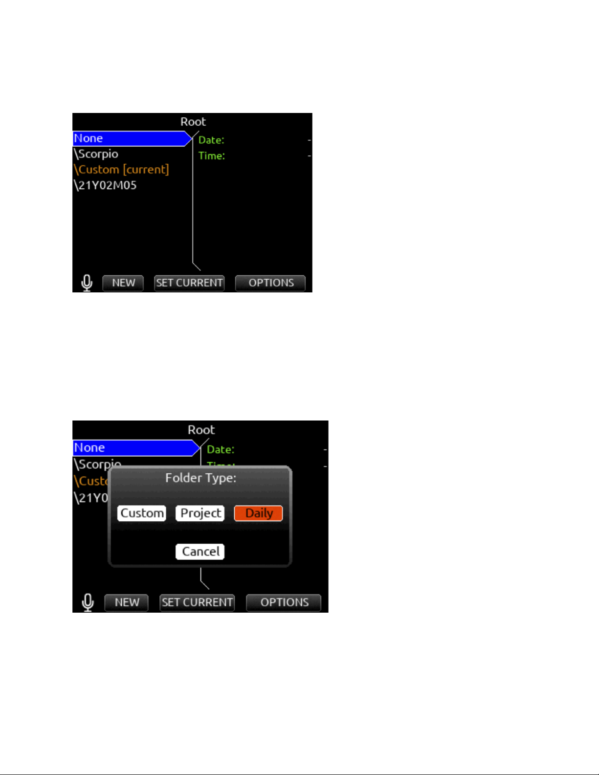
To create a new record folder in the folder level being viewed, select NEW (Tone toggle). The newly created record folder is
automatically set as the current record folder.
Select the Folder Type in the popup that appears. There are three types of record folder - Custom, Project, and Daily.
Custom
Files are stored in a custom-named folder; the Custom folder name is embedded as Tape metadata in the recorded audio files.
Project
Files are stored in a folder with a name determined by the Project name entered in the Take List > Next take Edit Screen. The
Project folder name is embedded as Tape metadata.
Daily
Files are stored in a folder whose name is in the format yyYmmMdd. When a Daily folder is selected, the Date is embedded as Tape
metadata.
When a daily folder is selected as the current record folder, a daily folder popup is displayed when the first recording after midnight
is completed. The daily folder popup displays the following message:
“Store this recording and subsequent recordings in the previous day’s folder or store in a new daily folder? [Previous], [New]”
● Select Previous to continue recording takes in the previous days folder.
● Select New to record in a new Daily folder.
Scorpio User Guide 44
Tip: To store new recordings in the root directory, highlight ‘None’ in the Root screen then select the */** toggle (SET Current). When
‘None’ is selected, the date is embedded as Tape metadata.
Any existing record folder can be set as the “current” record folder. Use the SET CURRENT */** toggle to set the highlighted folder
as the “current” record folder. The current record folder can be easily identified by the orange “[current]” tag following the folder
name.
Tip: To easily find the current record folder when it is nested within another folder, navigate the path indicated by orange record
folder names.
Tip: The Record Folder menu can also be accessed by selecting ‘Folder’ from the Take List>Next Take Edit screen. This also shows
the current record folder’s full path.
Tip: Program a Toggle Switch or map a shortcut for one-touch access to the Record Folder menu.
Record Folder Options
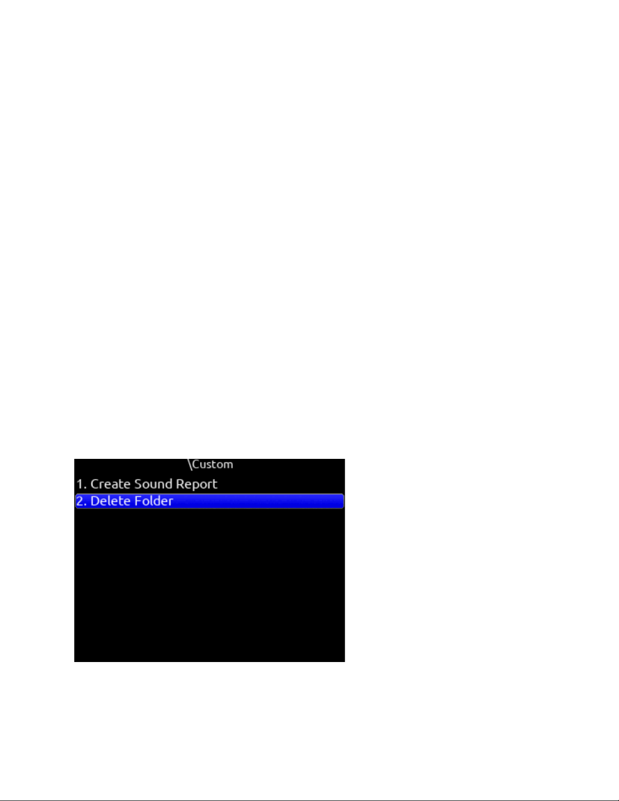
Highlight a record folder then select OPTIONS using the Rtn/Fav toggle. The following options are available:
Create Sound Report
Creates a sound report for the selected folder (not including its sub folders) on all 3 media. If there are no audio files in the selected
folder, a ‘No Takes Found’ popup is displayed.
The sound report’s filename format is [Date]_[RecFolderName]_Media.CSV, where Date is a 6-digit string based on the Date Format
setting in the System>Time/Date menu and Media = ‘ ‘ for SSD, ‘_1’ for SD1, and ‘_2’ for SD2.
For example: Rec Folder name = ROLL8, Date = 13th Aug, 2020 would appear as:
081320_ROLL8.csv (on SSD)
081320_ROLL8_1.csv (on SD1)
081320_ROLL8_2.csv (on SD2)
Delete Folder
Permanently deletes the selected record folder and all its contents including sub folders on all three media. This action cannot be
undone.
When the monophonic WAV file format is selected (in the Record/Play > Track to Media Routing menu), all mono files created for a
take follow the name of the take and are stored in a take folder within the selected record folder.
Scorpio User Guide 45
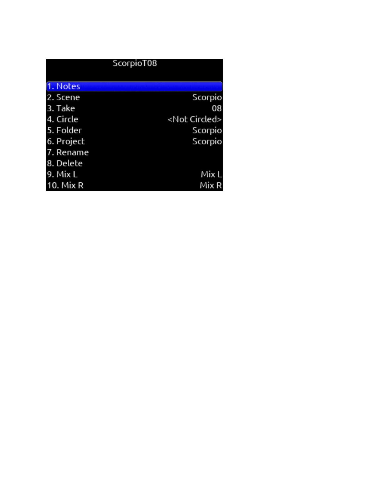
Take Edit Menu
1. Notes: Edit notes for the selected take. Maximum 200 characters including Sticky Notes.
2. Sticky Notes (next take only): edit sticky notes that are automatically prepended to subsequent takes. Maximum 50
characters.
3. Scene: Edit scene name. Maximum 50 characters.
4. Take: edit Take Number.
5. Circle (current or previous takes only): circle a take. Prepends “@” symbol to take name.
6. Project: Edit Project name. Maximum 20 characters. This will become the record folder name if Project is selected as the
Folder Type.
7. Delete (current or previous takes only): moves a selected take to a drive’s Trash folder.
8. Rename: Renames a take’s name. Project, Scene, and Take iXML/bEXT metadata are also updated provided renaming
does not change or delete the scene and/or take separator characters.
If a take is renamed and the edit doesn’t conform to the current Filename Format setting (with designators), it becomes a
freeform take name and metadata will not be updated.
If a take is renamed and the edit conforms to the current Filename Format setting (with designators), the metadata is
updated even after renaming a freeform take name.
If a take is renamed and the edit contains a letter following the take designator, the take number metadata is updated only
with the numbers immediately following the designator.
9. Track Names: Edit track names. Maximum 20 characters. A10-TX and A20-Mini transmitter names can be optionally used
to populate the associated isolated track names when used with the A20-Nexus, SL-2 and SL-6. For more information,
see ‘Use Wireless Names’ in the Channel Setup menu (for A20-Nexus) and SuperSlot options menu for SL-2 and SL-6.
The ‘+’ prefix is added if an existing take is edited such that it would duplicate the name of another existing take in the same record
folder. The ‘A’ suffix is added if the NEXT take’s name is edited such that when recording is started, it would duplicate the name of
an existing take in the same record folder.
Scorpio User Guide 46
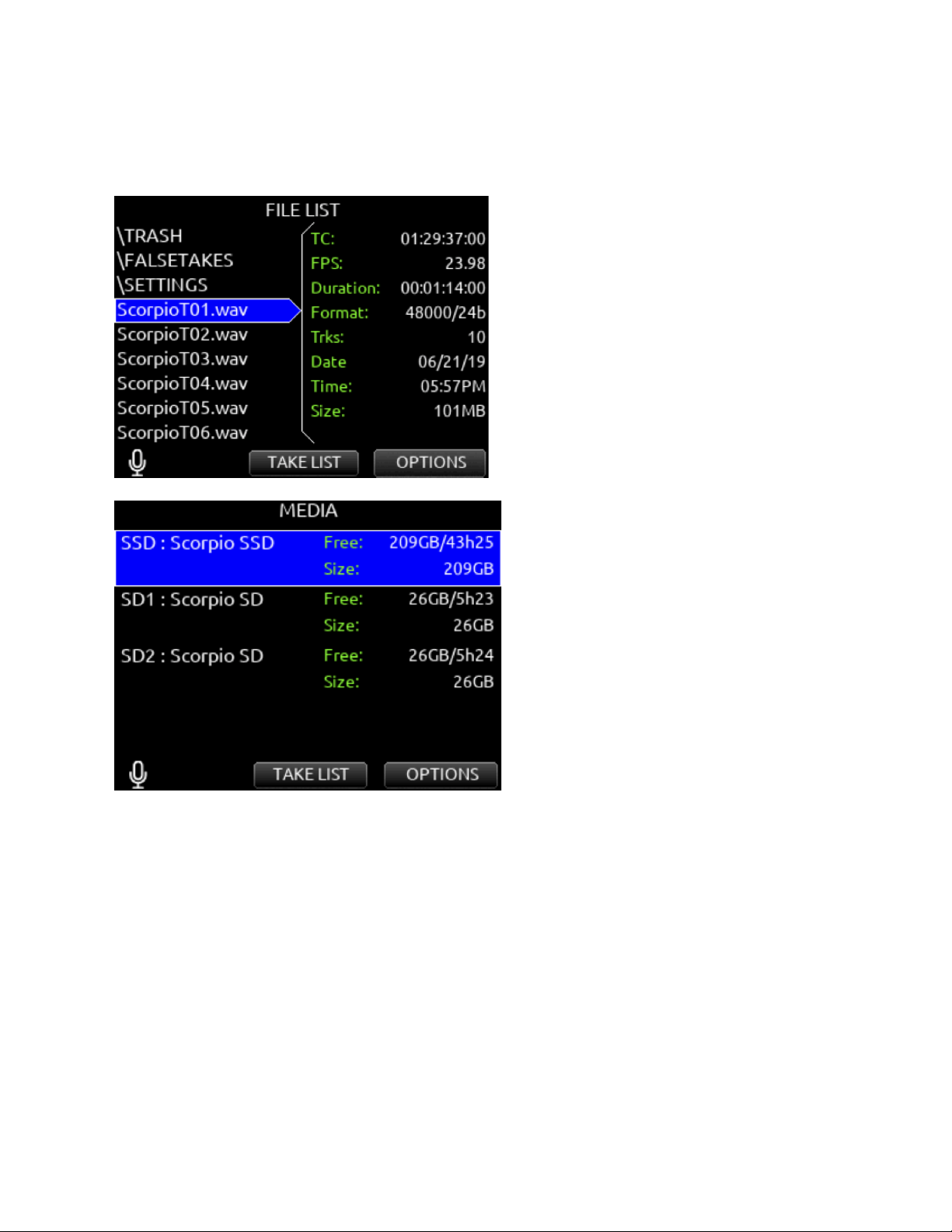
File List
Menu>Files>File List enters the File List. The File List displays the Scorpio’s internal SSD and SD cards and their contents. Various
details of each drive, folder, and WAV file are indicated on the right side of the display: TC, FPS, duration, format, tracks, date, time,
size.
The File List is also accessible from the Take List by pressing the Tone Switch.
Highlight any WAV file in the File List, then press play to play it back.
Scorpio User Guide 47
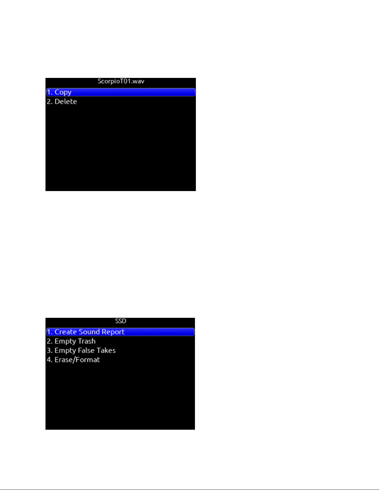
File List Options for files
Copy Folder/File
Provides support for copying Folders and Files between drives from the File List’s Options Menu.
Delete Folder/File
Delete Folders and Files from the File List’s Options Menu.
File List Options for Folders
Create Sound Report
Creates a CSV sound report for the selected folder’s takes.
The sound report’s filename format is MMDDYY_[RecFolderName][Media].csv where Media = ‘ ‘ for SSD, ‘_1’ for SD1, and ‘_2’ for
SD2
Rec Folder name = ROLL8, Date = 13th Aug, 2020 would appear as:
081320_ROLL8.csv (on SSD)
081320_ROLL8_1.csv (on SD1)
081320_ROLL8_2.csv (on SD2)
Tip: It is possible to simultaneously create sound reports on all three media for the current Record Folder by setting a Toggle Switch
Action, Controller Midi Mapped button, or GPIO to the ‘Create Sound Report’ function.
Empty Trash
Scorpio User Guide 48

Empties the trash folder.
Empty False Takes
Empties the false takes folder.
Erase/Format
Formats the selected drive.
SD1 and SD2 cards can be given a custom volume name during the format process.
Filename Format
Selectable naming conventions for recorded files. Selectable between Scene (Slate) T,+,- Take, or Project ;,%, = Scene (Slate) T,+,-
Take.
Sound Report Info
Selects the various content for each field of a sound report.
Scene Increment
Mode Defines whether a scene name shall be incremented numerically or alphabetically when the scene increment shortcut is used.
When set to ‘Character’, the last scene character will increment from A through Z, but skipping ‘I’ and ‘O’ to avoid being confused
with ‘1’ and ‘0’.
Take Reset Mode
Selects when a Take Number shall reset to 1. Options are: Never, Scene Change, Folder Change, Scene or Folder Change.
Erase/Format Internal SSD
Select to erase/format the internal SSD. Select OK when the “Format Internal SSD?” popup appears.
Erase/Format SD1
Select to erase/format SD1. Enter a custom volume name for the SD card when prompted.
Erase/Format SD2
Select to erase/format SD2. Enter a custom volume name for the SD card when prompted.
Frame.io
Allows connection to Frame.io and setup. See Frame.io for more details.
USB File Transfer
Enters USB file transfer mode. Files may be transferred between a Mac or PC and Scorpio via USB-C port.
When in USB file transfer mode, playback, record and controller functions are suspended.
Tip: Headphone gain can be adjusted while in File Transfer mode allowing HP volume change while listening to computer USB
audio when selected as a source for headphones.
Scorpio User Guide 49
Frame.io
Frame.io C2C (Camera-to-Cloud) is a service that allows automatic upload of Scorpio recorded files to the cloud as soon as they are
closed. Recorded files upload even while recording new ones. Should there be a loss of internet connection during an upload,
Scorpio auto-resumes upload from where it left off once connection is re-established. To upload to Frame.io, a Frame.io account
and/or invitation to add your Scorpio as a Cloud Device to a Frame.io Project is required.
Visit https://www.frame.io/c2c for further information.
To Connect to Frame.io
1. Establish an Internet connection by connecting the Scorpio’s Ethernet port to a router or LTE hotspot. The Scorpio’s
Network IP address is configured automatically from the router or hotspot’s DHCP server. The IP address is displayed in
the Files>Frame.io menu. Depending on the network environment, it may take a few minutes for the 888 to receive an IP
address.
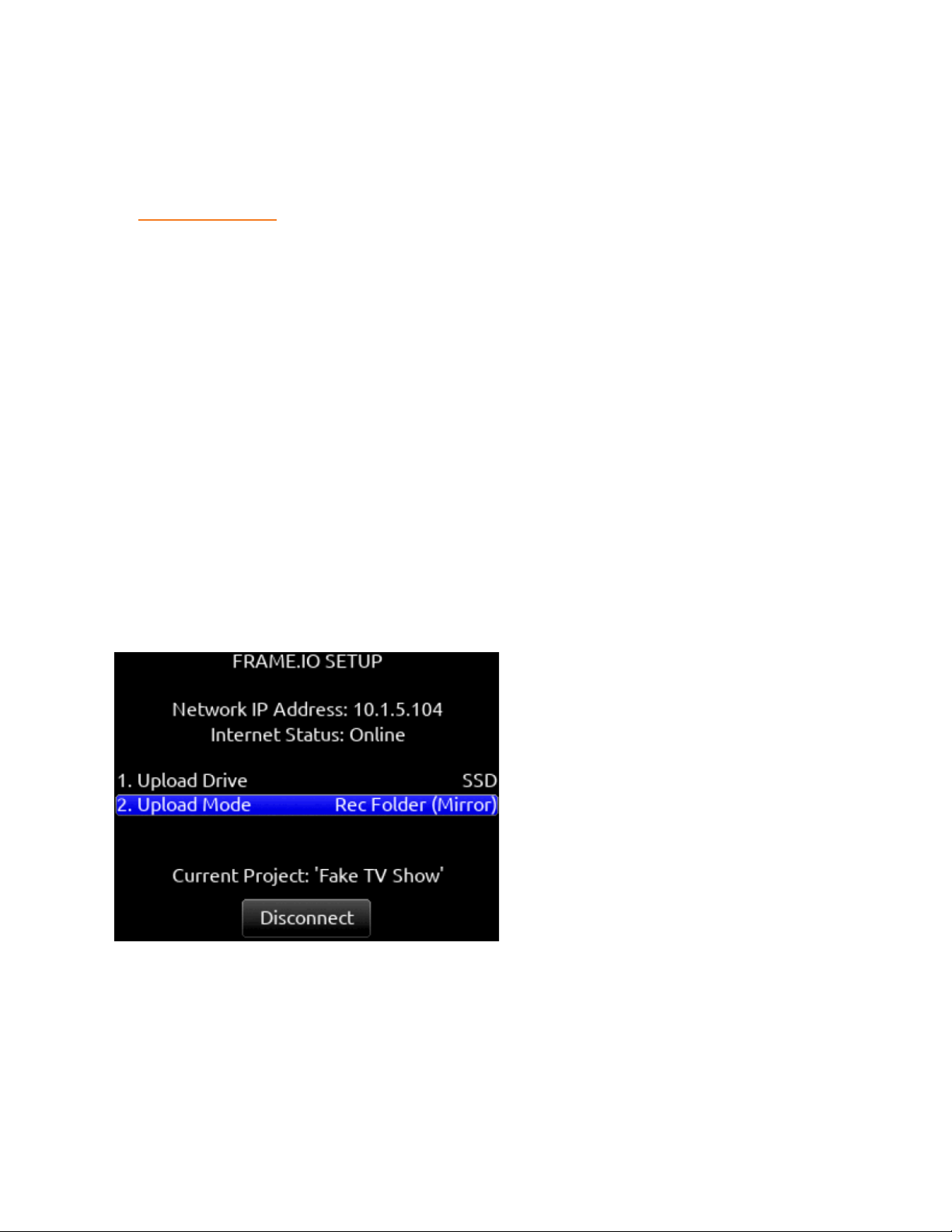
2. Wait for the Network IP address to be displayed in the Files>Frame.io menu.
3. Once the IP address is displayed, the Scorpio will automatically check Internet connection status. The Frame.io Setup
menu’s Internet Status field will display ‘Online’ if successfully connected to the Internet. If the Scorpio displays a valid
Network IP address but the Internet Status displays ‘Offline’, check that the router or hotspot is connected to the Internet.
4. If the IP address shows 0.0.0.0 (no IP address), check the Ethernet connection.
5. Connect the Scorpio as an authorized Cloud Device to the Frame.io Project.
6. From the Frame.io iOS app, a Frame.io Project with Cloud Device Integration enabled needs to be created.
7. In the Frame.io Project’s Cloud Devices Tab, select ‘Set up new device’. Select ‘Device ready to connect’. Frame.io app
displays ‘Enter the device pairing code’.
8. From the Scorpio Files>Frame.io menu, select Connect (*/** toggle). Within 30 seconds (depending on connection speed
and traffic), Scorpio displays the 6-digit device pairing code. Enter this 6-digit code in the Frame.io iOS app’s ‘Enter the
device pairing code’ screen, then tap the ‘Authorize’ button. Wait for authorization to complete.
9. If connection to the Frame.io Project is successful, “Connection to Frame.io successful” is displayed on theScorpio’s
screen. Click OK and confirm that the ‘Current Project’ field displays the name of the Frame.io Project. Dashes are
displayed if the Scorpio is currently not connected to any Frame.io project.
10. The Scorpio is now ready to upload files to Frame.io.
Tip: From any Meter View, you can easily confirm that you are actively connected to a Frame.io project. This is indicated by a light
blue rectangle box surrounding the selected Frame.io Upload Drive.
The Scorpio is now ready to upload files to Frame.io.
To Disconnect from Frame.io
From the Scorpio menu Files>Frame.io, select Disconnect (*/** toggle). Disconnecting de-authorizes the Scorpio as a contributing
Cloud Device to the Frame.io project.
If a take is already in the process of uploading when disconnecting from Frame.io, a popup appears with the options to disconnect
now or after the upload of the take in progress completes. Disconnect Now will leave an incomplete file and therefore unusable take
on the Frame.io server.
Scorpio User Guide 50
It is not necessary to reconnect to a Frame.io Project after power cycling the Scorpio. Reconnection to a Frame.io Project is only
necessary after disconnecting or when the Project expires. To find out more about Project expiration, visit Frame.io.
The Scorpio can only be connected to one Frame.io Project at a time. Disconnect from the current Frame.io project before
attempting connection to the new project.
Upload Drive
Choose which tracks (ISO, L/R, Bus 1/2) and file type (Mono, Poly, AAC) to upload to the Frame.io Project. First, in the Scorpio
Record/Play>Track to Media Routing menu, select tracks and file type for the SSD, SD1, and SD2. Then select Files>Frame.io>
Upload Drive and choose whether to upload from SSD, SD1, or SD2.
Upload mode
Choose whether to automatically upload all takes in the current record folder, new takes in the current record folder, manually upload
takes, or pause upload to Frame.io.
Rec Folder (Mirror)
Automatically uploads all takes in the Scorpio Record Folder to Frame.io
Rec Folder (New Takes)
Automatically uploads only takes that are recorded after entering this mode to Frame.io.
Take (Manual)
Manually upload individual takes from the Scorpio Take List to Frame.io. When set to Take (Manual), an ‘Upload to Frame.io’ option
is available in a take’s Edit screen.
Paused
Pauses uploading of takes to Frame.io. If a take is already in the process of uploading when the upload is paused, a popup appears
with the options to pause the upload now or after the upload of the take in progress completes. Pausing Now will leave an
incomplete and therefore unusable take on the Frame.io server. The take will be reuploaded to Frame.io when selecting another
Upload mode.
When in Paused mode, ‘P’ flashes in the meter view drive field and the Scorpio remains connected to the Frame.io Project.
Note: If file upload is interrupted due to loss of power or loss of Internet connection, the Scorpio automatically reconnects to
Frame.io and resumes uploading the file from where it left off.
Monitoring Frame.io Upload Status
Meter View
Blue rectangle box surrounding drive: Drive is set to upload and is connected to Frame.io
Flashing ‘-->’ icon on the drive icon: Drive currently uploading files to Frame.io.
Flashing ‘P’ on the drive icon: Upload Drive paused.
Scorpio User Guide 51
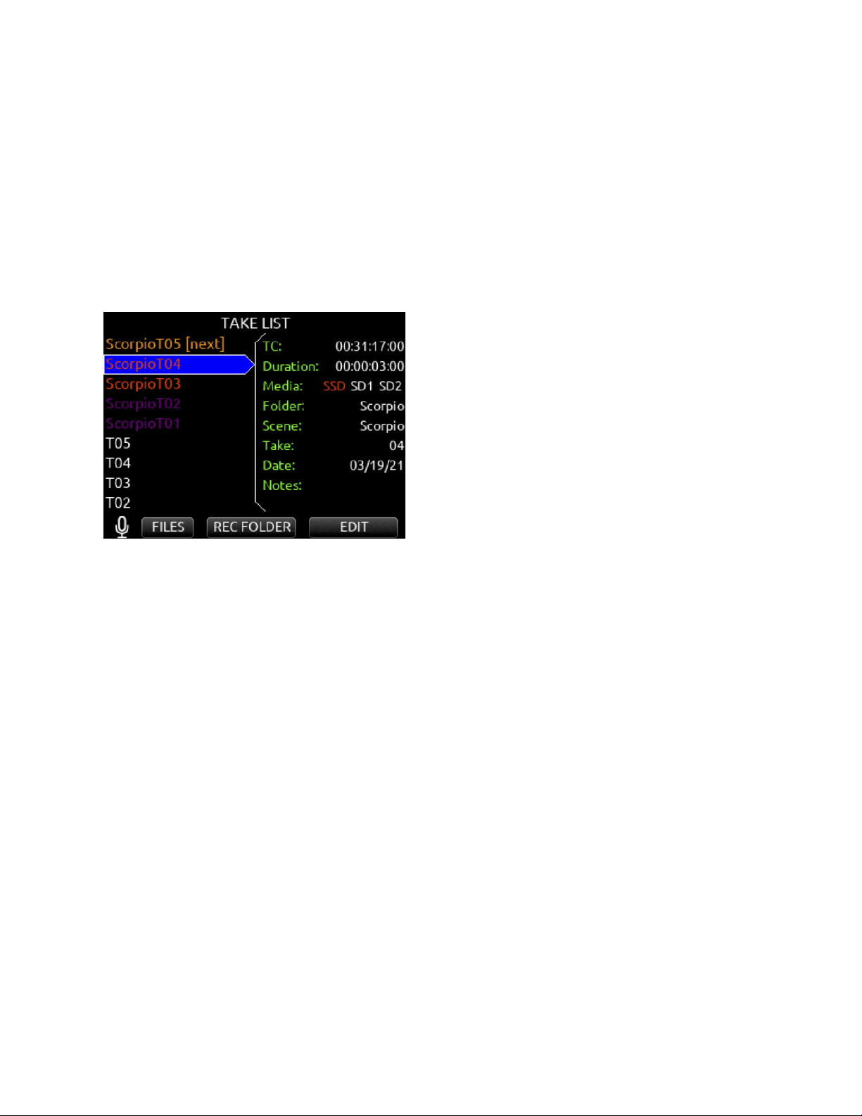
Take List
The Take List uses different colors to identify a take’s upload status.
Take List Left Pane:
● White take: Take not uploaded or queued for upload.
● Orange take: Take is uploading to Frame.io.
● Purple take: Take uploaded to Frame.io.
Take List Right Panel > Media:
● White SSD, SD1, or SD2: Take not uploaded to Frame.io from drive.
● Orange SSD, SD1, or SD2: Take is uploading to Frame.io from drive.
● Purple SSD, SD1, or SD2: Take uploaded to Frame.io from drive.
Frame.io Web Browser and iOS Apps
From the Frame.io Web Browser or iOS app you can:
● Confirm file upload
● Playback uploaded Scorpio WAV or AAC files
● Add comments to files for collaboration purposes
● Rename, Delete, Move, and Copy uploaded files
● Share and download files plus more
● For more information, visit Frame.io
Scorpio User Guide 52
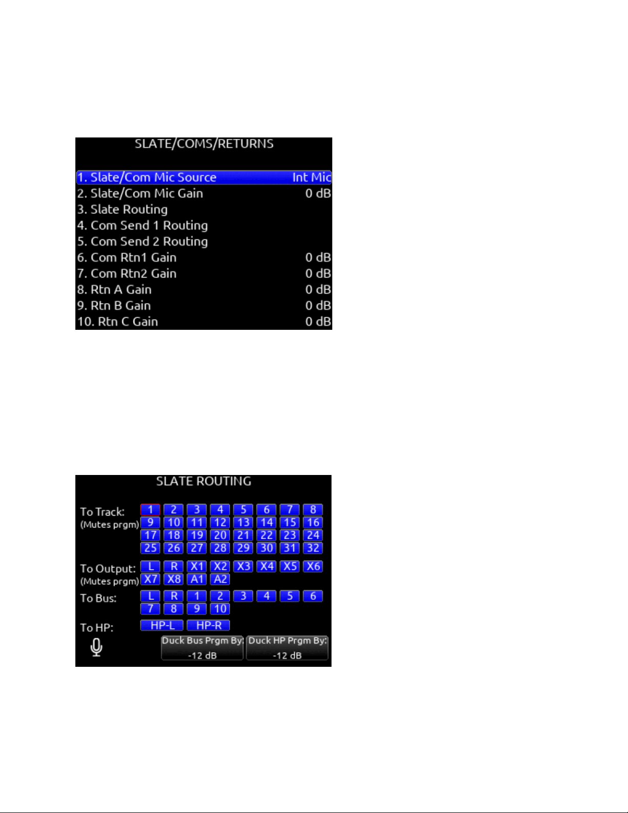
Slate/Coms/Returns
Slate/Com Mic Source
Selects the slate and com mic source. [Off, Int Mic*, Ext Mic, Ext 12 V Mic]
Slate/Com Mic Gain
Selects the gain for the slate/com mic. [-10 to 20 dB in 1 dB steps for the internal mic, 0 to 60 dB in 1 dB steps for the external mic].
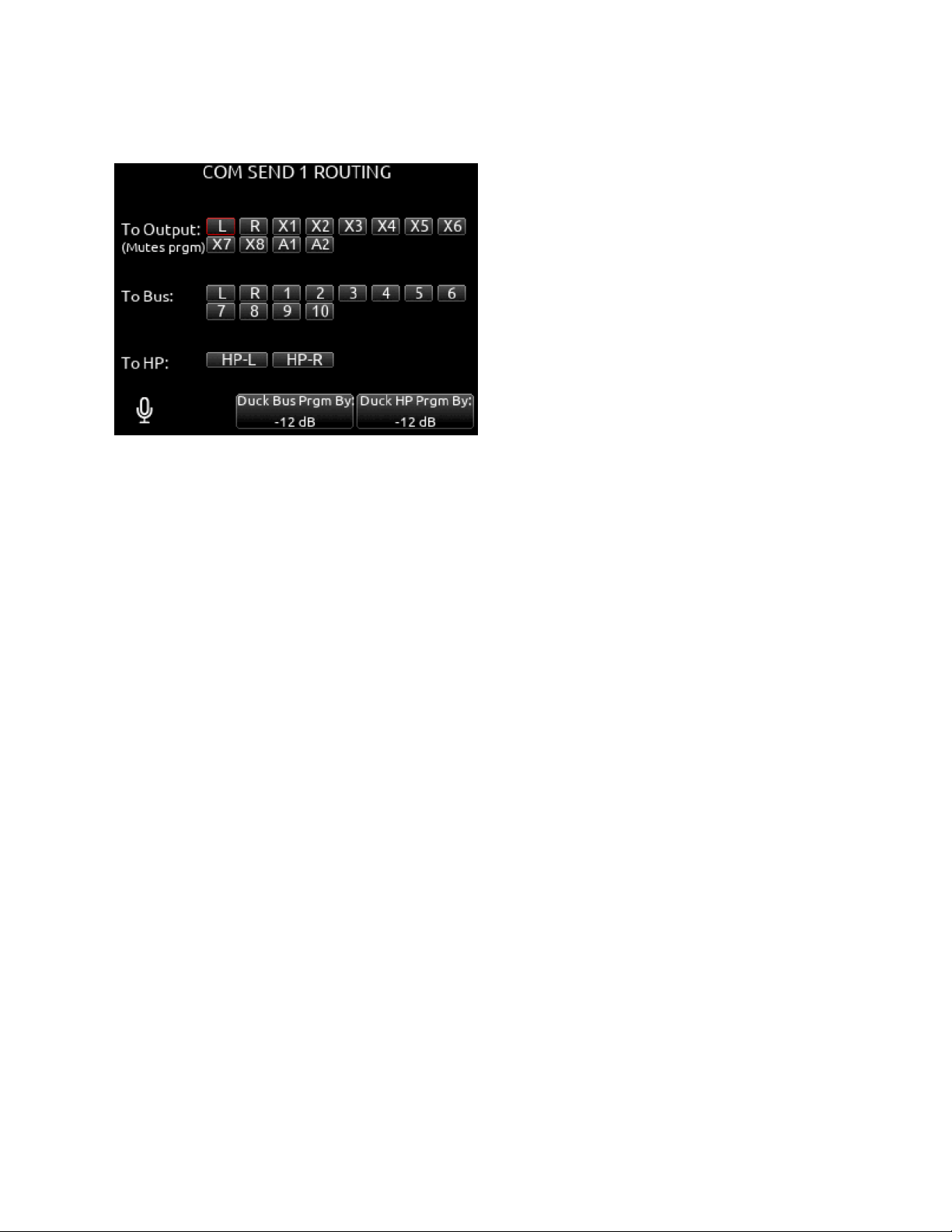
Slate Routing
Selects the destination(s) for the slate mic.
A. Track: [1-32]
B. Output: [L,R, X1-X8, A1,A2]
C. Bus: [L,R, 1-10]
D. HP: [HP-L, HP-R]
E. Duck Bus Prgm By: [0 to -40 dB, -inf]
F. Duck HP Prgm By: [0 to -40 dB, -inf]
Com Send 1 Routing
Selects the destination(s) for Com Send 1.
A. Output: [L,R, X1-X8, A1,A2]
B. Bus: [L,R, X1-X8]
C. HP: [HP-L, HP-R]
Scorpio User Guide 53
D. Duck Bus Prgm By: [0 to -40 dB, -inf]
E. Duck HP Prgm By: [0 to -40 dB, -inf]
Com Send 2 Routing
Selects the destination(s) for Com Send 2.
A. Output: [L,R, X1-X8, A1,A2]
B. Bus: [L,R, X1-X8,
C. HP: [HP-L, HP-R]
D. Duck Bus Prgm By: [0 to -40 dB, -inf]
E. Duck HP Prgm By: [0 to -40 dB, -inf]
Com RTN1 Gain
Selects the gain for Com Rtn 1 in 1 dB increments. [0-30 dB]
Com RTN2 Gain
Selects the gain for Com Rtn 2 in 1 dB increments. [0-30 dB]
RTN A Gain
Selects the gain for Rtn A in 1 dB increments. [0-30 dB]
RTN B Gain
Selects the gain for Rtn B in 1 dB increments. [0-30 dB]
RTN C Gain
Selects the gain for Rtn C in 1 dB increments. [0-30 dB]
Duck Bus Program By
Ducks all audio sent to the bus by a user defined amount.
Duck HP Program By
Ducks all audio sent to headphones by a user defined amount.
When sending coms or slate signal to outputs the program routed to that output is replaced by the com or slate signal.
Scorpio User Guide 54
SuperSlot
When combined with Scorpio, the SL-2 and SL-6 SuperSlot wireless accessories offer integrated control of SuperSlot compatible
receivers, monitoring, powering, and RF distribution for multiple channels of wireless audio.
Selecting the SuperSlot menu item (or shortcut Meter+HP) navigates directly to the Rx Overview screen. This screen varies based
on which SuperSlot accessory is attached to Scorpio.
See SL-2 Receiver Overview and SL-6 Receiver Overview for more details.
The SuperSlot menu is grayed out and inaccessible unless either a Sound Devices SL-2 Dual SuperSlot Wireless Module or a SL-6
Powering and Wireless System is attached to the Scorpio.
The SL-2 or SL-6 Receiver Slot Power or the 8-Series power must be cycled after performing any action that causes a receiver to
reboot. Powering receivers on and off from the receiver’s user interface is not supported.
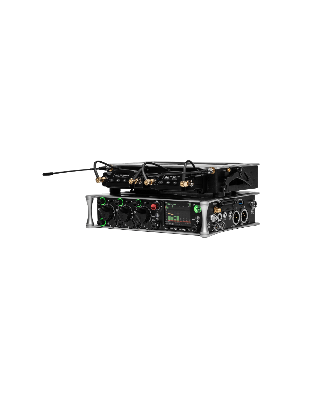
SL-2
The SL-2 (shown above on an 833) is a two slot-in wireless receiver integration system that easily mounts to the top panel of any
8-Series mixer-recorder. It accepts UniSlot and SuperSlot™ wireless receivers from a variety of manufacturers. Power to the SL-2
and receivers is supplied by the 8-Series Mixer-Recorder – no external DC connector is needed on the SL-2. Analog or digital audio
is sent from the receivers into the mixer-recorder via the expansion port, reducing messy cabling for power and audio connectivity.
The SL-2 offers antenna distribution to slot-in receivers, spreading out the placement of antennas for better RF performance.
Additionally the SL-2 allows for control of smart antennas and includes two filtered antenna outputs to external receivers via MCX
ports. The rear panel of the SL-2 is equipped with two TA3 connectors for an additional four inputs of AES3 audio and two 4-pin
Hirose DC Outputs, each supplying up to 500 mA.
Up to eight channels of audio can be routed from the SL-2 to the Scorpio. The eight channels can be comprised of audio from dual
or quad channel slot in receivers and/or the four AES inputs.
The SL-2 mounts to the Scorpio via the multi-pin expansion port located on the top panel. Please refer to the SL-2 User Guide for
panel descriptions and installation instructions.
Scorpio User Guide 55

WARNING! To avoid potential hardware damage, turn off power to the SL-2 slot prior to removing and inserting receivers. Slot
power can be turned off in Menu>System>Expansion Port, Menu>SuperSlot>Options>Slot Power, or by powering off the 8-Series
Mixer-Recorder.
Supported SuperSlot receivers for use in the SL-2 are:
● Sound Devices A20-RX
● Audio Ltd. A10-RX
● Lectrosonics SRb, SRc, SRc-941, SRb5P (Slot A only), SRc5P (Slot A only)
● Lectrosonics DSR4 (4ch digital audio per slot)
● Lectrosonics DSR
● Sennheiser EK6042 (does not support scan)
● Shure ADX5D
● Sony DWR-S03D
● Wisycom MCR42
● Wisycom MCR54 (4ch digital audio per slot)
Powering the SL-2
The SL-2 is powered by the Scorpio via the Expansion Port. No additional power source is needed to power the SL-2.
To activate the SL-2, set the System>Expansion Port menu to On.
Save power when the SL-2 is not in use by setting the Expansion Port menu to Off. When the Expansion Port is set to Off, the
SuperSlot menu is grayed out.
Routing SL-2 Sources to Channels
The SL-2 has 12 selectable sources and can send up to 8 channels of audio to the mixer/recorder. 8 channels are available if all
sources are AES digital. If a slot receiver output is analog, 6 channels are available and AES 3 and 4 cannot be selected.
To route an SL-2 Source to a channel, access a channel’s source screen and select from A1-A4, B1-B4, AES 1-4. When A1-A4,
B1-B4 are selected as source, use the */** toggle as a shortcut to the selected receiver’s setup screen.
For SL-2 A1-A4, B1-B4, and AES 1-4 sources, channel trim gain range is -20 to 50 dB.
When an A10-RX/A20-TX is receiving signal from an A20-Mini or A20-TX, the trim gain of the associated 8-Series channel is 0 to 60
dB. See GainForward.
GainForward
RF Overload LEDS Each antenna input on the front panel of the SL-2 has an associated LED that displays incoming RF level status.
Red = approaching RF overload threshold of the SL-2
Orange = approaching overload threshold of digital wireless systems
Off = no overload
To disable the LEDs go to SL-2 Options>Antenna LEDs and set to Off.
Scorpio User Guide 56
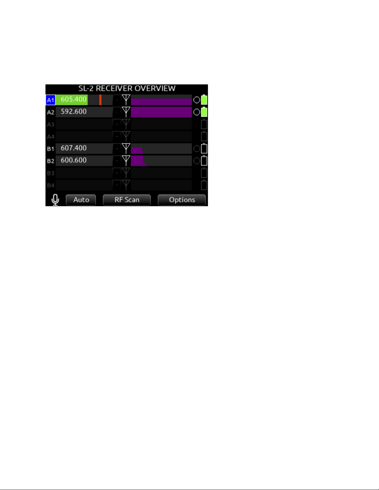
SL-2 Receiver Overview
Select the SuperSlot menu to enter the SL-2 Receiver Overview screen which displays information for all receivers connected to the
SL-2. Hold Meter then press the HP knob to quickly access the Receiver Overview screen.
A1-A4, B1-B4 Use the Select knob to scroll and select an SL-2 channel to access the individual Receiver Setup screen. See
Receiver Setup Screen for more details.
Post-Trim Channel Metering
Displays the post-trim audio level of the Scorpio channel receiving audio from the SL-2 source. When the SL-2 source is not routed
to a Scorpio channel, no signal is displayed on the meters.
RF Frequency
Displays the frequency of the receiver in MHz.
Transmitter Battery Level Displays the battery level of the paired transmitter, if applicable.
Green = over 50%
Yellow = over 20%
Orange = over 10%
Red = less than 10%.
Transmitter Record Status
Indicates the record status of the paired transmitter, if applicable. Red = recording
Transmitter Status Box (A20-RX/A10-RX only)
A10-TX: Indicates paired transmitter Mute, Limiter, and Audio Overload status.
A20-Mini, A20-TX: Indicates paired transmitter Mute status. The Limiter and Audio Overload indicator are displayed for the 8-Series
channel receiving the A20-Mini or A20-TX signal.
Blue with ‘M’ = Transmitter Mute On
Yellow with ‘L’ = Limiting
Red with ‘O’ = Audio Overload
RF Level History
Displays the RF level over a period of time. Duration of RF History is set in SL-2 Options>RF History Duration parameter from 30 to
600 seconds in 10 s steps, default duration is 30 seconds. The taller the green bar, the healthier the received RF signal. A yellow
bar signifies receiver is approaching RF overload (A20-RX only). A red bar signifies receiver RF overload (A10-RX and A20-RX
only).
RX Antenna Icon Indicates RF signal status.
Solid white = locked to antenna signal
Flashing white = antenna signal unlocked
Solid Red = antenna signal overload
Gray = no receiver detected
Scorpio User Guide 57
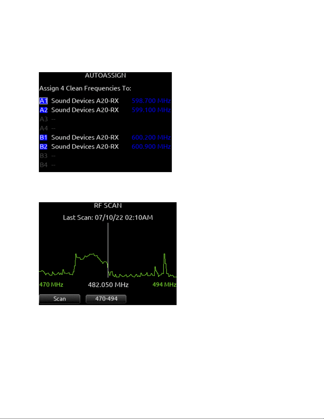
Auto (A20-RX only)
Starts scanning for clean frequencies to auto-assign to receiver channels. Use the Tone toggle to start the process. When the
AutoAssign scan is complete, the AutoAssign screen is displayed. Use the Select knob to select which receiver channels to assign
the clean frequencies to. A selected channel displays the clean frequency that will be assigned. Press the HP knob to assign the
clean frequencies to the selected channels.
RF Scan
Instigates an RF Scan of the environment using one or both receivers depending on the receiver model. Use the */** toggle switch to
start the scan..
Options
Access the SL-2 Options menu by using the Rtn/Fav toggle switch.
Scorpio User Guide 58
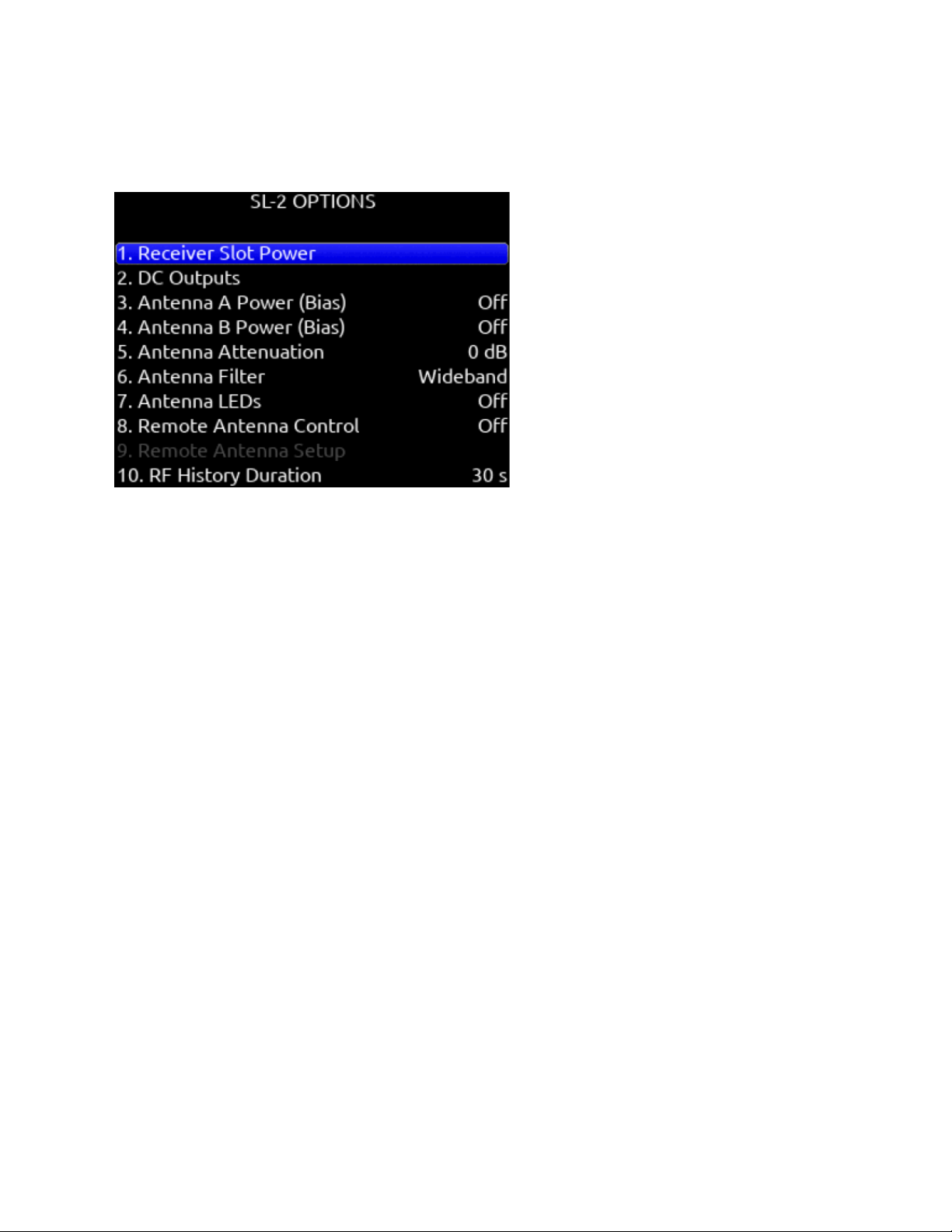
SL-2 Options
Provides access to various SL-2 settings.
Receiver Slot Power
Each slot can be individually turned On/Off to save power when not in use. Powering receivers on and off from the receiver’s user
interface is not supported.
DC Outputs
Enable/disable DC Outputs 1 and/or 2.
Antenna A/B Power (bias)
Provides 12 V DC bias power for active or smart antennas.
Antenna Attenuation
Apply attenuation to reduce the possibility of RF overload. Select from 0 to -18 dB in 6 dB steps.
Antenna Filter
Select the SL-2’s front end filter to reduce the likelihood of out-of-band RF noise affecting range. Select from Wideband, 169-235
MHz, 470-614 MHz, 542-694 MHz, 606-770 MHz, 770-960 MHz, 1240-1525 MHz.
Antenna LEDs
Antenna LEDs can be toggled On*/Off.
Remote Antenna Control
Enables/disables Remote (Smart) Antenna Control.
Remote Antenna Setup
See “Remote Antenna Setup” details below.
RF History Duration
Sets the duration of the RF HISTORY plot. Select from 30 to 600 seconds in 10 second steps, default duration is 30 seconds.
Use Wireless Names
The name associated with the receiver channel is automatically applied to the isolated track receiving the signal. This feature is
supported by the Audio Ltd. A10-RX, A20-RX, Shure ADX5D, and the Wisycom MCR54.
Unislot Audio Mode
Enables the manual selection of analog or digital audio output from a Unislot slot receiver This allows for receivers that support
digital audio but that are not supported in 'SuperSlot' mode.
Scorpio User Guide 59
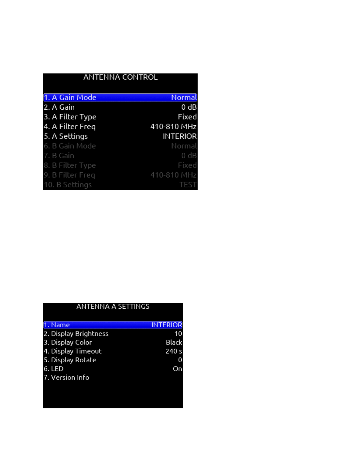
Remote Antenna Setup
Configures the various settings for connected remote (smart) antennas. The menu is grayed out if Remote Antenna Control is Off
and/or no remote antenna is detected. A remote antenna requires bias power. The SL-2 supports the Wisycom LFA smart antenna
and BFA smart filter.
Antenna A/B Gain
Sets gain of Antenna A or B in 1 dB steps. [Off, Bypass, -12 to 27dB]
Antenna A/B Filter Type
Sets the filter type of Antenna A or B. [Tunable, NB, or WB] (Selected in Freq field: 410-810, 410-700, 410-600, 470-810, 470-700,
470-600, 510-810, 510-700, 510-600); NB (940-960MHz, freq is fixed at 940-960 and cannot be changed)]
Antenna Frequency
Sets the filter freq of Antenna A or B. Frequencies available depend on the Wisycom LFA/BFA model, F1, F2, F3, or F6. Please refer
to the Wisycom documentation for filter frequency detailed information. [When Filter is set to NB, Frequency is fixed at 940-960 and
cannot be changed. When Filter is set to WB, Freq can be set to 410-810, 410-700, 410-600, 470-810, 470-700, 470-600, 510-810,
510-700, 510-600. When Filter is set to Tunable, Filter Frequency can be adjusted in 40 MHz blocks from 410-450 to 690-730 in 1
MHz steps.]
Antenna A/B Settings
Provides access to additional Antenna A or B settings.
Scorpio User Guide 60

Name
Displays name of Antenna A/B.
Display Brightness
Sets Antenna A/B display brightness in increments of 1. [1-10]
Display Color
Sets Antenna A/B display color. [White, Black]
Display Timeout
Sets the duration of Antenna A/B display timeout in steps of 1 second. [5 to 240 seconds]
Display Rotate
Sets the rotation of the Antenna A/B display. [0 or 180]
LED
Sets Antenna A/B LED activity. [On or Off]
Version Info
Displays system information about the Wisycom LFA-B-F1.
Scorpio User Guide 61

SL-6
When combined with Scorpio, the SL-6 offers easy integration of multiple channels of wireless connectivity, mixing, recording and
power management in a lightweight and easy to use package. The SL-6 simplifies interconnection between the Scorpio and multiple
channels of wireless by accepting three dual-channel slot-in receivers providing a total of six separate audio feeds. Easily attaching
to Scorpio’s top panel, the SL-6 offers all powering and audio interconnection for standard slot-in receivers and additional control
and monitoring when used with SuperSlot compatible receivers. The SL-6 also distributes RF from external antennas to the
receivers, creating a more efficient, compact configuration.
The SL-Riser accessory is required for connection of the SL-6 to Scorpio. See the SL-Riser installation instructions here:
https://www.sounddevices.com/sl-riser-assembly/
The Scorpio must be powered via the SL-6 DC or NP-1 power source to use the SL-6.
WARNING! Remove all batteries and disconnect DC inputs from both the SL-6 and Scorpio prior to connecting the SL-6 to the
Scorpio. Failure to remove power could result in damage to the hardware.
Supported SuperSlot receivers for use in the SL-6 are:
● Sound Devices A20-RX
● Audio Ltd. A10-RX
● Lectrosonics SRb, SRc, SRc-941, SRb5P (Slot B or C only), SRc5P (Slot B or C only)
● Sennheiser EK6042 (does not support scan)
● Shure ADX5D
● Sony DWR-S03D
● Wisycom MCR42
● Wisycom MCR54 (2 channels per receiver only)
Scorpio User Guide 62
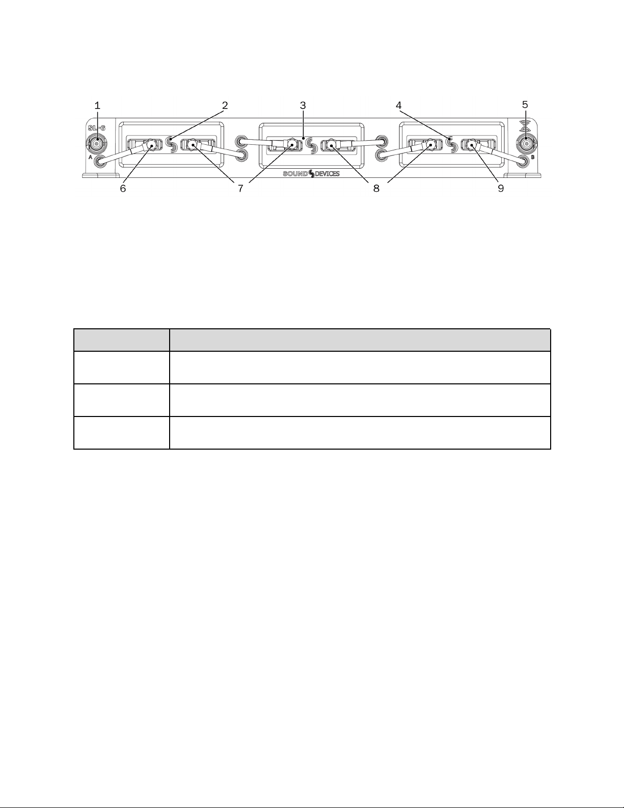
SL-6 Front Panel
1. Antenna Connector A
2. Receiver Slot A
3. Receiver Slot B
4. Receiver Slot C
5. Antenna Connector B
6. Antenna Distribution Lead (A)
7. Antenna Distribution Lead (B)
8. Antenna Distribution Lead (A)
9. Antenna Distribution Lead (A)
Feature
Description
Receiver Slots
Each slot accepts one (single- or dual-channel) SuperSlot or Unislot receiver. The connection provides
power to the receiver and connects the receiver’s audio output directly to the Scorpio.
Antenna Distribution
leads
SMA connectors with right-angle adapters are used to connect receivers to the SL-6 antenna
distribution system.
Antenna Connectors
BNC connectors are used for attaching external antennas to the SL-6 antenna distribution system. Use
BNC to SMA adapters, included with the SL-6, for antennas with SMA connectors.
Scorpio User Guide 63
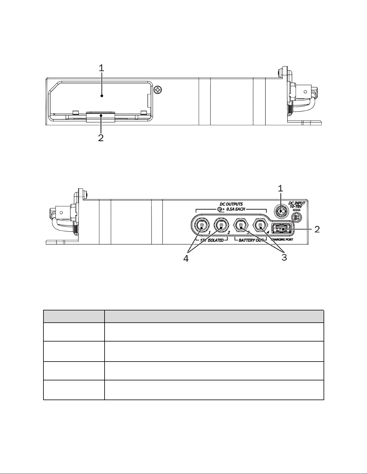
SL-6 Left Panel
The left panel of the SL-6 provides the NP-1 battery compartment, which accepts NP-1 batteries (14 V, Li-ion).
1. NP-1 Battery Compartment
2. Metal Retainer Tab
SL-6 Right Panel
1. Hirose 4-pin SC Input
2. USB Charging Port Power Only (5V DC)
3. Coaxial DC Outputs (12V)
4. Coaxial DC Outputs (12V Isolated)
Feature
Description
Hirose 4-pin DC Input
Hirose 4-pin DC input for powering the SL-6 and Scorpio. Power must be attached to this connector
or an NP-1 battery must be inserted to power the SL-6 and Scorpio.
Coaxial DC Outputs
(12 V Isolated)
Isolated 12 V DC outputs that draw from the active SL-6 power source (Hirose 4-pin or NP-1). Each
output is on by default but can be switched off from the Power section of the Main menu.
Coaxial DC Outputs (12 V)
12 V DC outputs that draw from the active SL-6 power source (Hirose 4-pin or NP-1). Each output is
on by default but can be switched off from the Power section of the Main menu.
USB Charging Port
Standard USB 5 V DC output that draws from the active SL-6 power source (Hirose 4-pin or NP-1).
The USB port on the SL-6 is designed for charging only, not for data transfer.
Scorpio User Guide 64
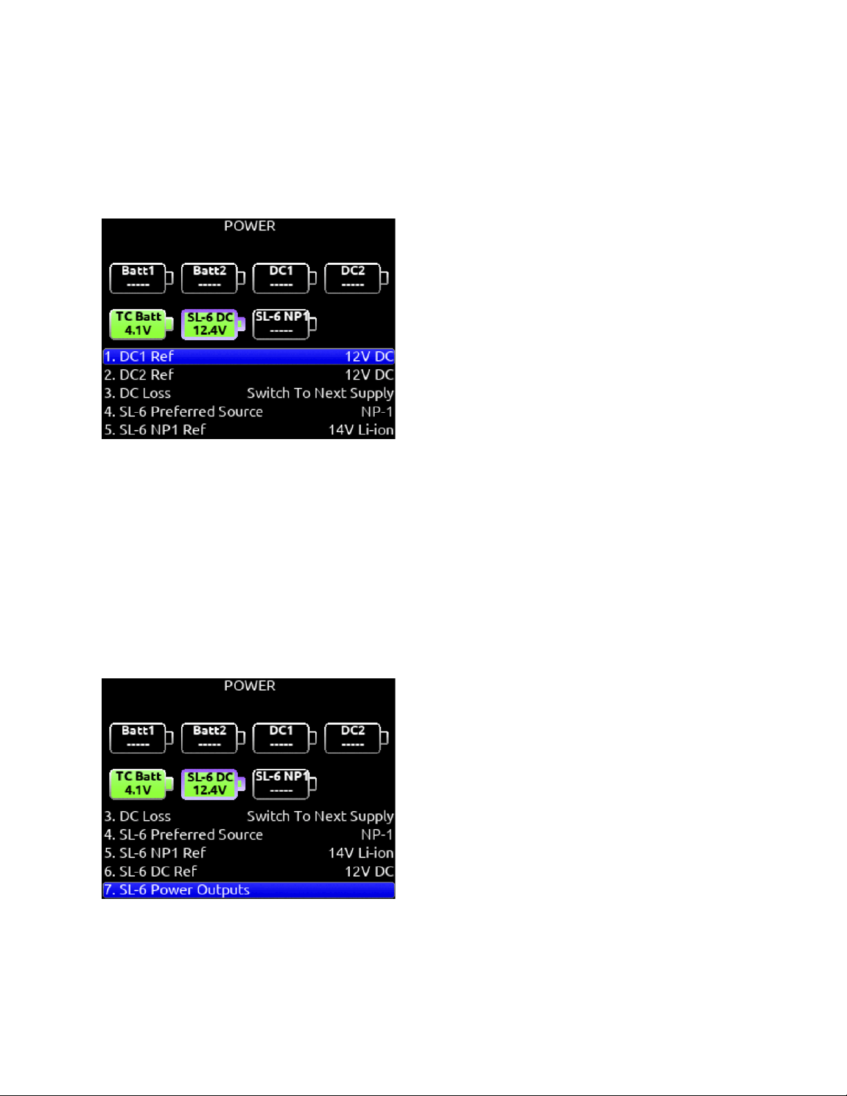
Powering with the SL-6
The SL-6 features two power inputs: NP-1 battery and external DC. The SL-6, its attached receivers, the Scorpio, and any devices
powered from the SL-6 DC outputs require one of these power sources to operate. When both SL-6 power sources are depleted or
disconnected, the SL-6 PowerSafe™ battery will keep the SL-6 and attached devices powered for 10 seconds while recording is
stopped as long as an L-mount or DC power source is connected to Scorpio.
Power sources connected directly to the Scorpio (external DC or the L-mount batteries) will not power the SL-6 or any peripheral
devices attached to the SL-6.
Remove DC1 and DC2 powering from the Scorpio while using the SL-6. L-Mount batteries can be left inserted in Scorpio while the
SL-6 is being used.
When an SL-6 is attached, the following settings are available in the
Power menu.
SL-6 Preferred Source
Selects whether the NP-1 or DC input takes priority.
SL-6 DC Ref
Allows proper power level based on the type of DC power source used [12 V DC, 14 V Li-ion, 12 V Lead Acid, Full Range]
SL-6 Power Outputs
Selects whether SL-6 power outputs 1-4 and USB charging port are on or off.
When using an external BDS switch to power the entire Scorpio/SL-6 system, set DC Loss to ‘Turn Off’ and ensure no NP-1 battery
is connected to the SL-6 and no DC power is connected to the DC-1 or DC-2 jacks on the Scorpio. Leaving these power sources
connected will cause the Scorpio to auto-reboot after powering down the BDS. L-Mount batteries can be left inserted in Scorpio and
will not cause a reboot after powering down from an external BDS.
Scorpio User Guide 65
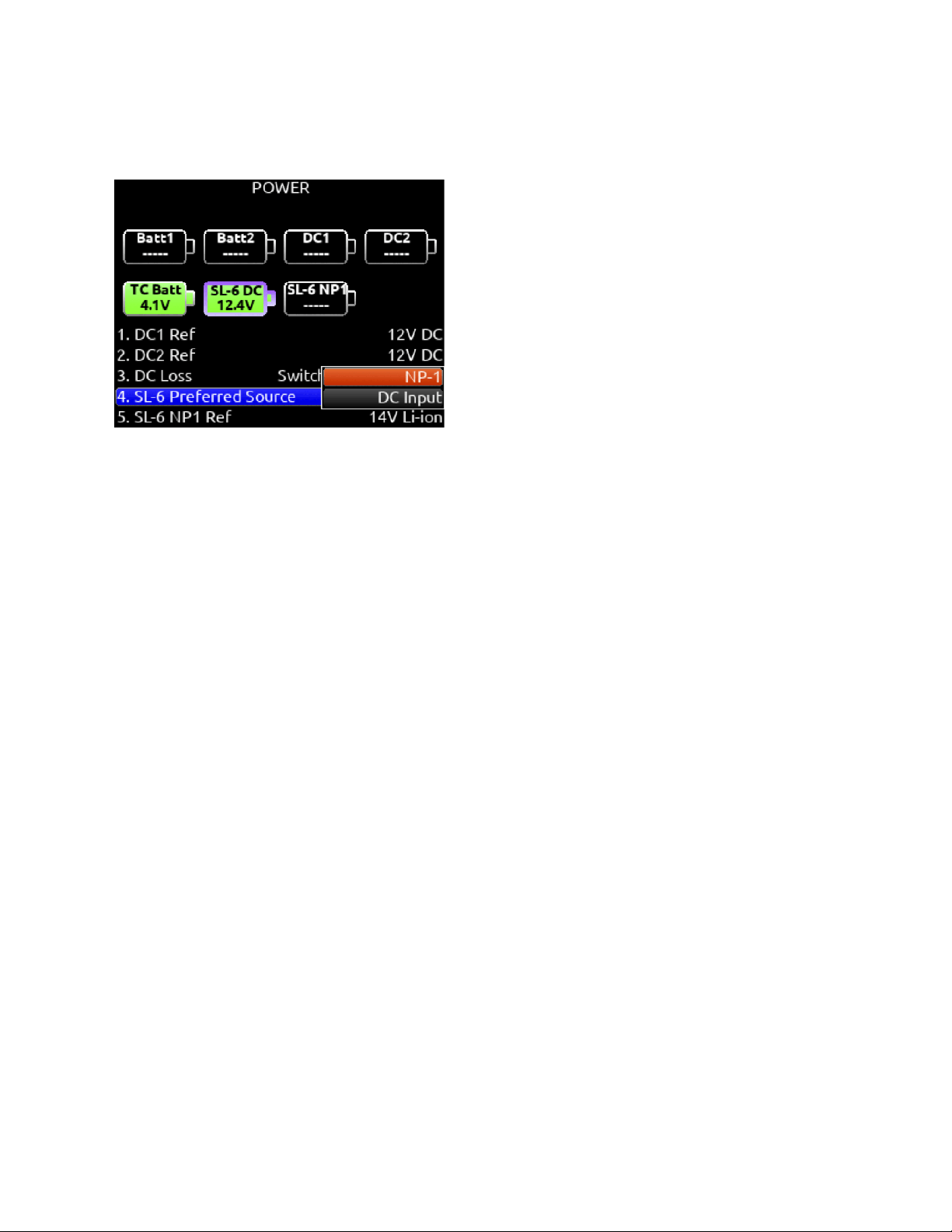
Routing SL-6 Sources to Channels
The SL-6 has a total of six channels of wireless from the three slots. To route an SL-6 Source to a channel, access a channel’s
source screen and select from A1, A2, B1, B2, C1, or C2. When an SL-6 channel is selected as the source, use the */** toggle as a
shortcut to the selected receiver’s setup screen.
For SL-6 A1-A2, B1-B2, C1-C2, channel trim gain range is -20 to 50 dB. When the A10-RX or A20-RX are receiving signal from the
A20-Mini or A20-TX, the trim gain of the associated 8-Series channel is 0 to 60 dB.
See GainForward.
SL-6 Receiver Overview
Select the SuperSlot menu to enter the SL-6 Receiver Overview screen which displays information for all receivers connected to the
SL-6. Hold Meter then press the HP knob to quickly access the Receiver Overview screen.
A1, A2, B1, B2, C1, C2
Use the Select knob to scroll and select an SL-6 channel to access the individual Receiver Setup screen. See Receiver Setup
Screen for more details.
Post-trim Channel Metering
Displays the post-trim audio level of the Scorpio channel receiving audio from the SL-6 source. When the SL-6 source is not routed
to a Scorpio channel, no signal is displayed on the meters.
RF Frequency
Displays the frequency of the receiver in MHz.
Transmitter Battery Level
Displays the battery level of the paired transmitter, if applicable.
Green = over 50%
Yellow = over 20%
Orange = over 10%
Red = less than 10%.
Transmitter Record Status
Indicates the record status of the paired transmitter, if applicable.
Red = recording
Auto (A20-RX Only)
Starts scanning for clean frequencies to auto-assign to receiver channels. Use the Tone toggle to start the process. See SL-2
section for further details.
RF Scan
Instigates an RF Scan of the environment using one or both receivers depending on the receiver model. Use the */** toggle switch to
start the scan.
Options
Access the SL-6 Options menu by using the Rtn/Fav toggle switch.
Scorpio User Guide 66
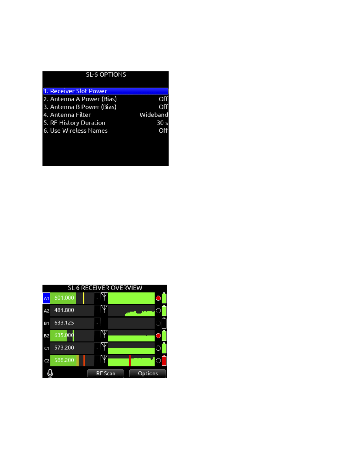
SL-6 Options
Provides access to various SL-6 settings including:
Receiver Slot Power
Each slot can be individually turned On/Off to save power when not in use.
Powering receivers on and off from the receiver’s user interface is not supported.
Antenna A and B Power (BIAS)
Provide 12V DC bias power for active or smart antennas.
Antenna Filter
Select the SL-6’s front end filter to reduce the likelihood of out-of-band RF noise affecting range. Select from Wideband, 470-700
MHz, 470-590 MHz, 580-700 MHz.
RF History Duration
Sets the duration of the RF HISTORY plot. Select from 30 to 600 seconds in 10 second steps, default duration is 30 seconds.
Use Wireless Names
The name associated with the receiver channel is automatically applied to the isolated track receiving the signal. This feature is
supported by the Audio Ltd. A20-RX/A10-RX, Shure ADX5D, and the Wisycom MCR54.
Scorpio User Guide 67
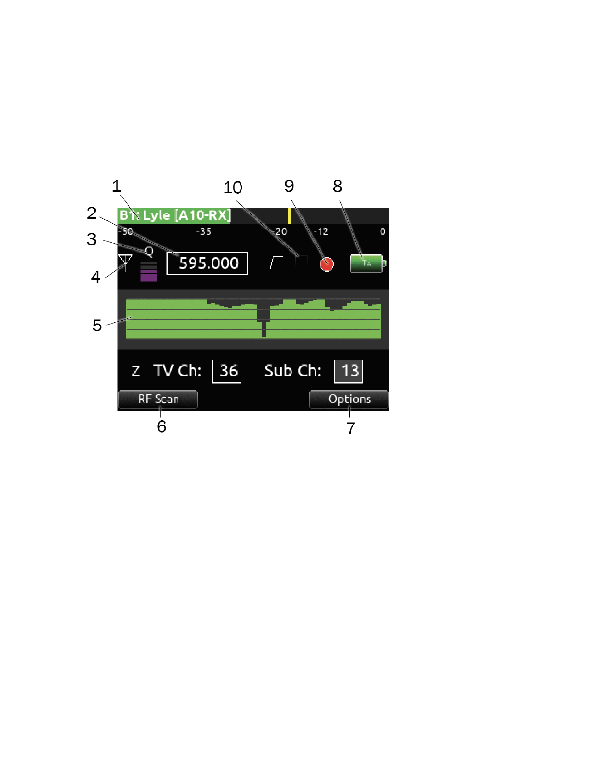
Receiver Setup Screens
When the SL-2 or SL-6 is attached, you can access Receiver Setup screens for any of the supported SuperSlot receivers available.
Receiver Setup screens provide access to individual receiver RF scanning, menus for receiver setup, RF frequency adjustment, RF
and audio level monitoring, transmitter recording status, transmitter Limiter/Overload/Mute status (A10-RX, A20-RX only), and more.
The transmitter status and menu settings available depend on the receiver.
Access the Receiver Setup screen from within the Receiver Overview screen by selecting the receiver channel (A1-A4, B1-B4 on
the SL-2 or A1, A2, B1, B2, C1, C2 on the SL-6) using the Select knob.
1: Post-trim Channel Metering
Displays the post-trim audio level of the Scorpio channel receiving audio from the SL-6 or SL-2 source. When the SL-6 or SL-2
source is not routed to a Scorpio channel, no signal is displayed on the meters.
2: RF Frequency
Set Receiver channel frequency in MHz or by TV channel and Sub channel.
A20-Mini: Indicates paired transmitter mute status. The limiter and audio load indicator are displayed for the 8-Series channel
receiving the A20-Mini signal.
Blue with ‘M’ = TX Mute On
Yellow with ‘L’ = Limiting
Red with ‘O’ = Audio Overload
3: Q-meter
The A20-RX/A10-RX Q-meter displays the difference between the signal from the transmitter and any interference using five bars.
When a frequency without little to no interference is selected, the Q-meter will display five bars. Some third party receiver’s have
their own version of this meter.
4: RX Antenna Icon
Indicates RF signal status.
Solid white = locked to antenna signal
Flashing white = antenna signal unlocked
Solid Red = antenna signal overload
Scorpio User Guide 68
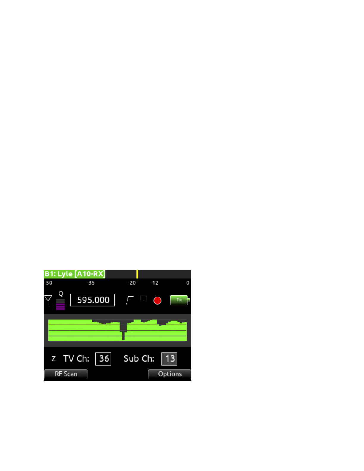
Gray = no receiver detected
(Not applicable to the Lectrosonics SRb/SRc which uses ‘P’ to indicate pilot tone lock status.)
5: RF Level History
Displays the RF level over a period of time. Duration of RF History is set in SuperSlot>SL-2/SL-6 Options>RF History Duration
parameter from 30 to 600 seconds in 10 s steps, default duration is 30 s. The taller the bar, the healthier the received RF signal.
The RF History Levels setting determines the source of the data drawn. RSSI is displayed in green and Quality in purple. The RF
History Levels option is available on Audio Ltd A10-RX, Sound Devices A20-RX, Shure ADX5D, and Wisycom MCR54. A yellow bar
signifies receiver is approaching RF overload (A20-RX only). A red bar signifies receiver RF overload (A10-RX, A20-RX, and Shure
ADX5D only). An orange bar signifies RF interference (Shure ADX5D only).
6: RF Scan
Instigates an RF Scan of the environment using an individual SuperSlot receiver. Use the Mic/Tone toggle switch to start the scan. A
red line signifies the squelch level of the Wisycom MCR54 and MCR42. Squelch level is only displayed in individual RX Scan
screens and not in the RF Overview Scan screen.
7: Options
Provides access to additional settings of the selected receiver. Options vary depending on the manufacturer and model of the
receiver selected. Please refer to the user guide provided by the manufacturer of the receiver for more details.
8: TX Battery Level
Displays the battery level of the paired TX, if applicable.
Green = over 50%
Yellow = over 20%
Orange = over 10%
Red = less than 10%.
9: TX Record Status
Indicates the record status of the paired transmitter, if supported. Red = recording
10: TX Status Box (A20-RX/A10-RX only)
A10-TX: Indicates paired transmitter mute, Limiter, and Audio Overload status.
A20-RX/A10-RX
Scorpio User Guide 69
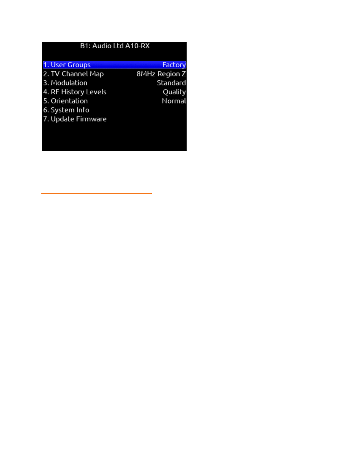
GainForward (A20-Mini)
The A20-Mini transmitter introduces GainForward, a new feature that eliminates the need to adjust microphone preamplifier gain at
the wireless transmitter. Audio levels from the transmitter are controlled directly at the mixer’s trim control. If the talent speaks too
softly or emotes too loudly after being “wired” with the transmitter, simply adjust the transmitter gain with the mixer’s gain trim. Read
more about GainForward at:
https://www.sounddevices.com/gainforward-explained/
Adjusting Audio of the A20-Mini Signal from Scorpio
When the A20-RX/A10-RX receiving A20-Mini signal is slotted into the SL-2 or SL-6, the A20-RX/A10-RX Input menu settings are
bypassed and all gain, low cut, and limiter activity are performed and controlled by Scorpio. See the A20-Mini/A20-TX and
A20-RX/A10-RX User Guides for more information.
When Scorpio is receiving A20-Mini or A20-TX signal via SuperSlot the Scorpios’ trim gain is adjustable from 0 to 60 dB. The
A10-RX or A20-TX Receiver screens display the associated Scorpio channel’s low cut, audio overload, and limiter activity.
A10-TX does not support GainForward.
Use Wireless Names For Track names
A10-TX and A20-Mini transmitter names can be set to automatically be applied as the Scorpio’s isolated track name for the channel
receiving the signal. Set Use Wireless Names to On in the SL-2 or SL-6 Options menu.
Third-Party Supported SuperSlot Receivers
The following pages show the Receiver Setup screens and the options menus for third-party supported SuperSlot receivers. Refer to
the manufacturer for full details on features and functionality of these receivers.
Scorpio User Guide 70
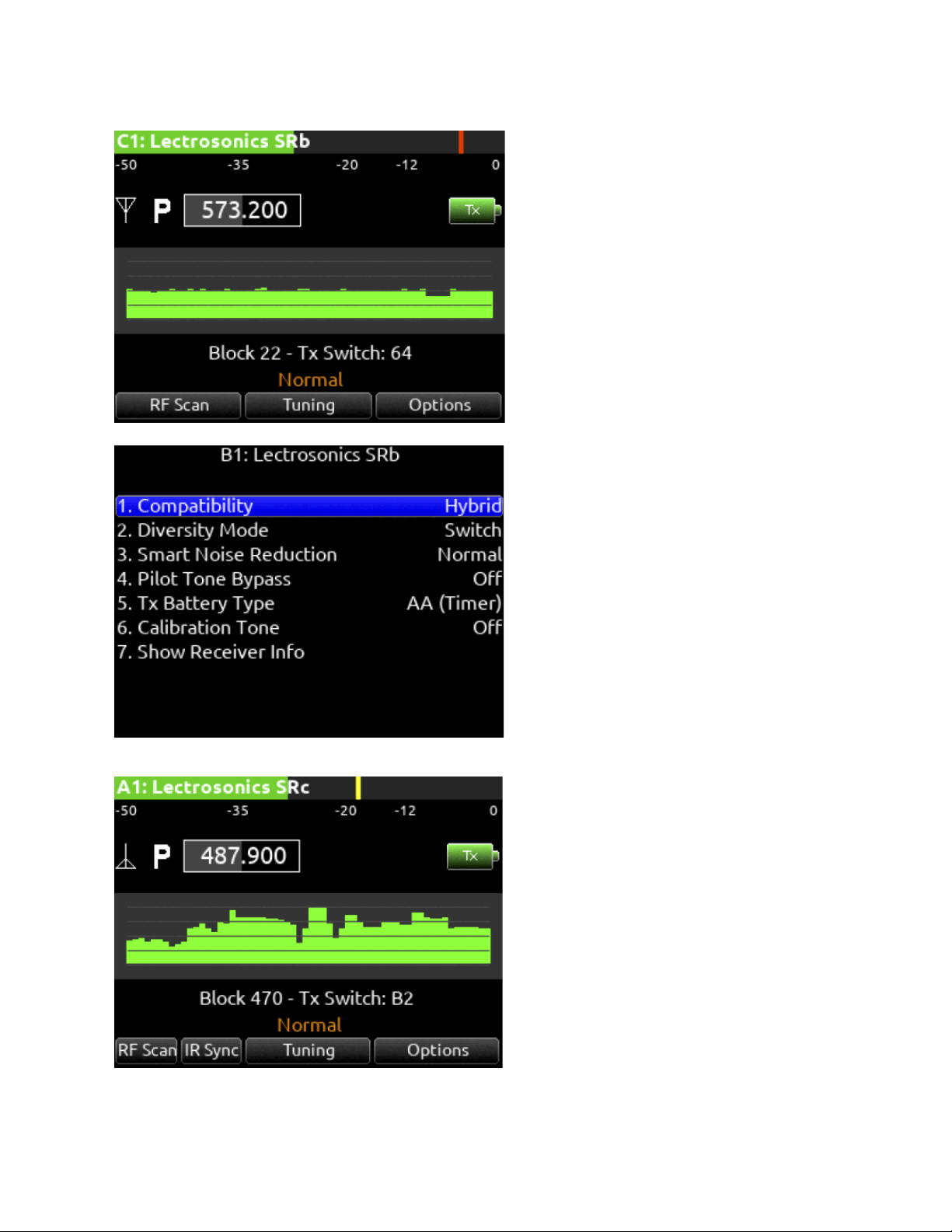
Lectrosonics SRB
Lectrosonics SRC
Scorpio User Guide 71
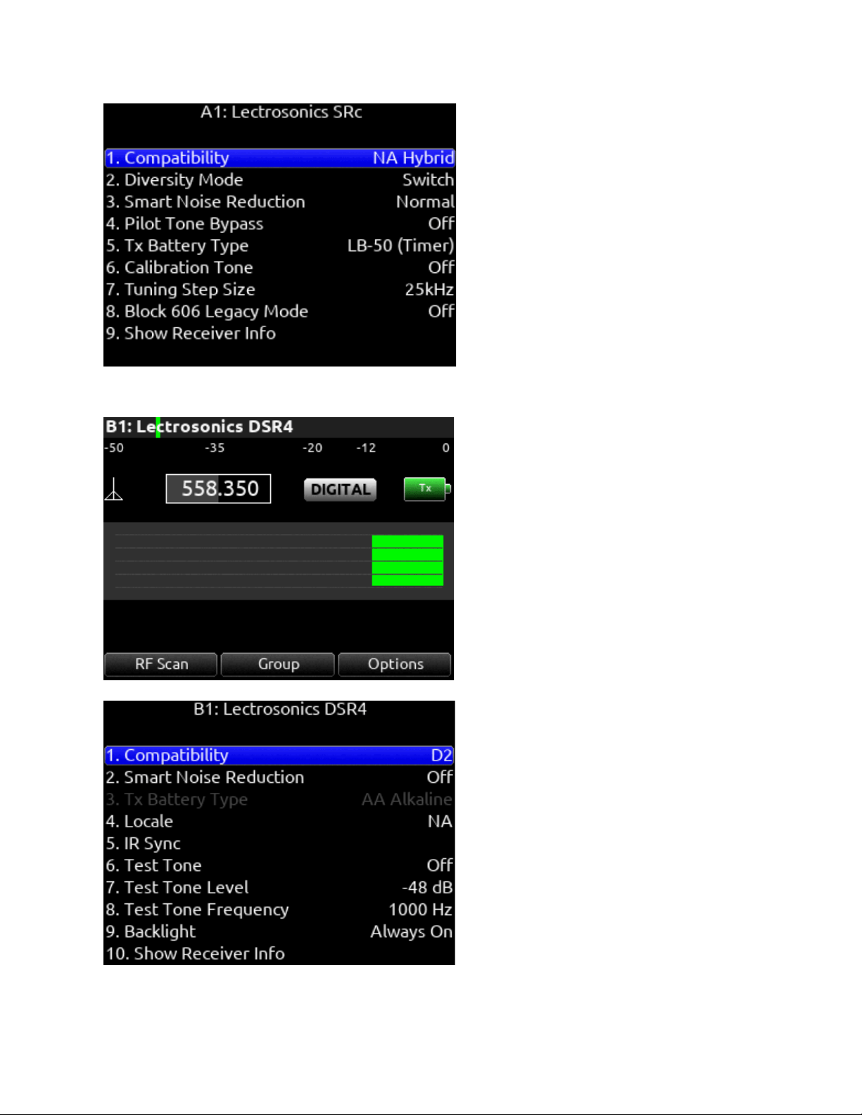
Lectrosonics DSR4
Scorpio User Guide 72
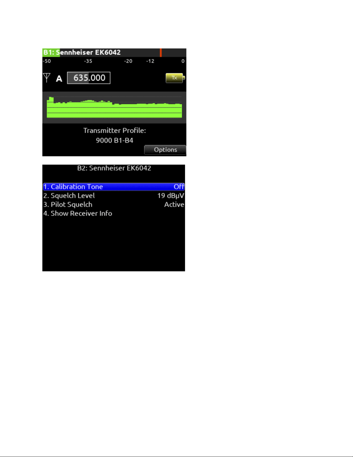
Sennheiser EK6042
Scorpio User Guide 73
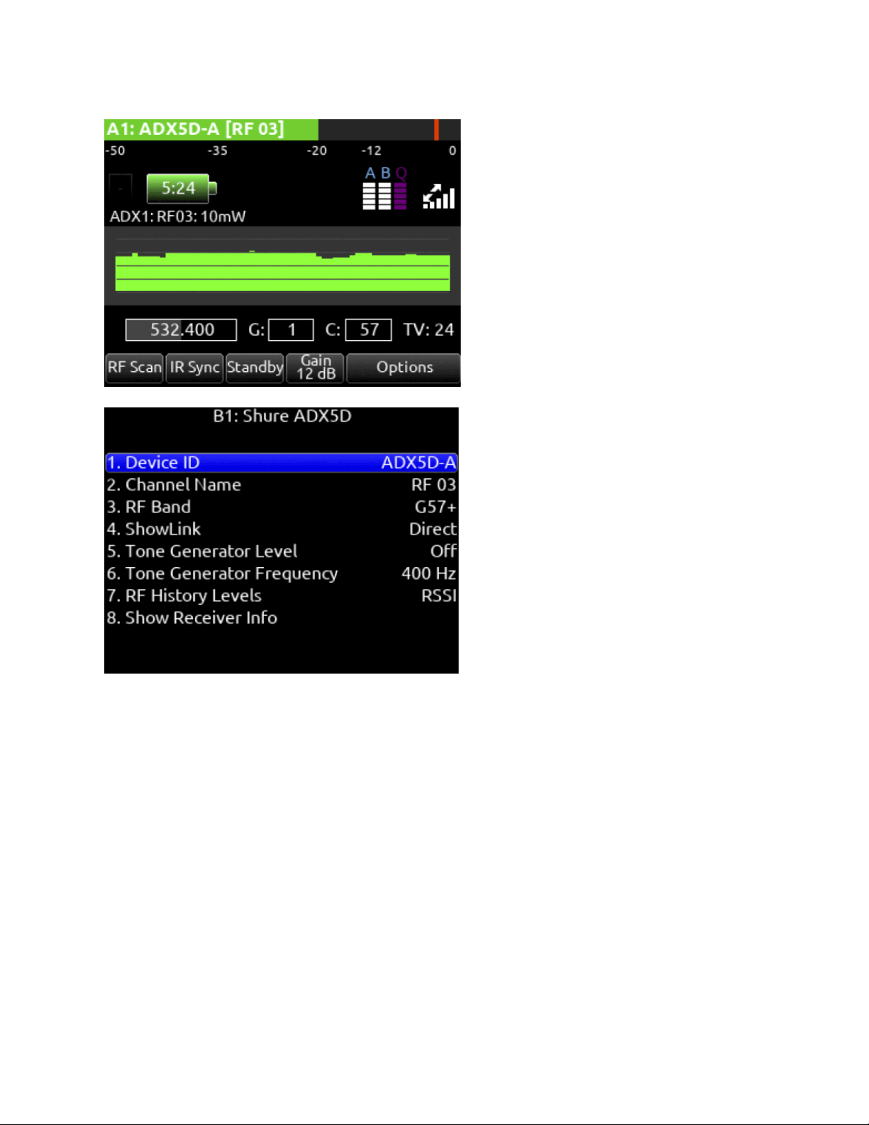
Shure ADX5D
The SL-2 or SL-6 Receiver Slot Power or the 8-Series power must be cycled after performing any action from the Shure ADX5D
user interface requiring the receiver to reboot. This includes powering the Shure ADX5D on and off, changing Transmission Mode,
changing 3rd Party Control, or performing a Factory Reset.
SuperSlot Control of the Shure ADX5D is only available when Device Cfg >> Advanced >> 3rd Party Control is On.
When the Shure ADX5D is in High Density Transmission mode, Groups and Channels must be set from the ADX5D interface.
Scorpio User Guide 74
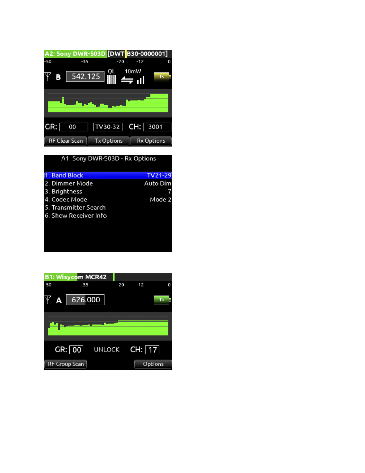
Sony DWR-S03D
Wisycom MCR42
Scorpio User Guide 75
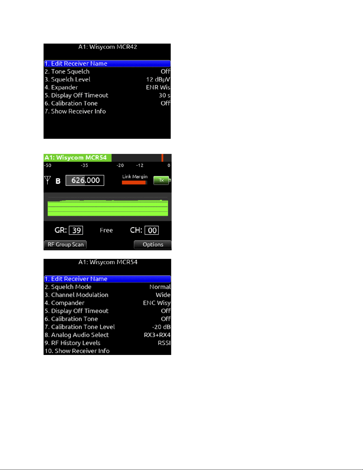
Wisycom MCR54
Scorpio User Guide 76

A20-Nexus/A20-Nexus Go
The A20-Nexus and A20-Nexus Goare ultra-high performance, multichannel wireless microphone receivers in a compact ½-rack
wide chassis that can be docked to Sound Devices 833, 888, or Scorpio mixer-recorder using the A20-QuickDock accessory, which
provides convenient power, audio, and timecode connections with no cables. This accessory allows the A20-Nexus and A20-Nexus
Go to connect and disconnect from the 833, 888, or Scorpio in seconds with no tools.
See the online A20-Nexus, A20-Nexus Go User Guides for more detailed information.
Scorpio User Guide 77
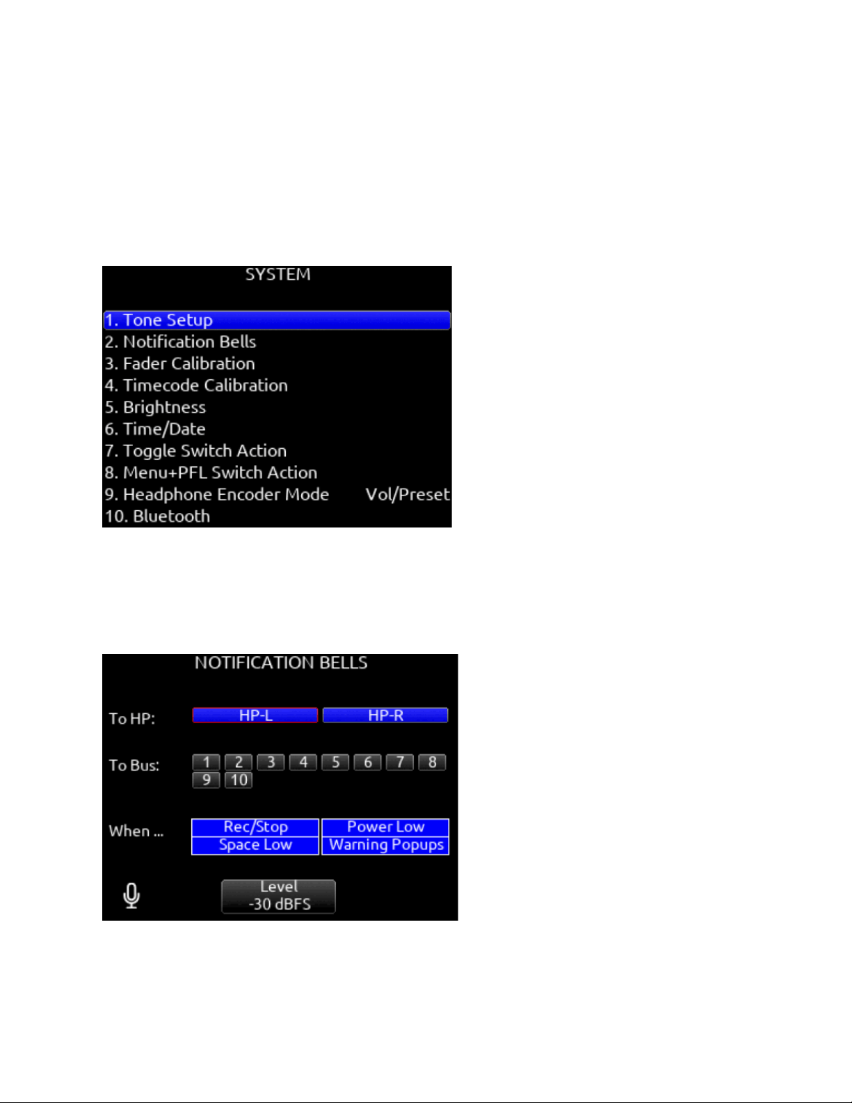
System
Tone Setup
Selects the level, frequency, and routing of the internal tone generator.
A. Level- Selects the level of the tone generator from -20 - 0 dBFS in 1 dB increments. [-20 - 0 dBFS]
B. Frequency- Selects the frequency of the tone from 100 to 10 kHz in 10 Hz steps. [100-10 kHz]
C. Track- [1-32]
D. Output- [L,R, X1-X8]
E. Bus- [L,R, 1-10] (Use toggle Switch Action menu to select tone as Continuous or L-ident.)
Notification Bells
Selects settings for the notification bells.
A. To HP- Routes notification bell tones to the headphones. [HP-L, HP-R]
B. To Bus- Routes notification bell tones to the buses. [L,R, 1-10]
C. When…- Selects when the notification bell tones are used. [Rec/Stop, Space Low, Power Low, Warning Popup]
D. Level- Selects the level at which the notification bell tones will be played in 1 dB increments. [Muted, -60 to -12dBFS]
Fader Calibration
Selects the option to manually calibrate all faders.
Scorpio User Guide 78

Timecode calibration
Select Timecode Calibration to tune the system clock to an external LTC signal. This can be used to ensure zero TC drift between
the Scorpio and external timecode devices. Select Reset to Factory Calibration to return to the factory calibration setting.
Note: Calibration values are stored in the Scorpio’s saved settings files. When loading a settings file created using another Scorpio,
it is highly recommended to perform a ‘Reset to Factory Calibration’ or ‘Timecode Calibration’ after loading the settings, otherwise
the calibration settings from the other machine will be used which could result in noticeable timecode drift.
Brightness
Selects the brightness of the LED display and front panel LEDs.
A. LED Brightness- Selects the front panel LED brightness in 1% steps. [1%-100%]
B. Selects the front panel LCD display brightness in 10% steps. [10%-100%]
Time/Date
Selects the current date and time.
A. Time Format- [12*, 24 hr]
B. Date Format- [mm/dd/yy*, dd/mm/yy, yy/mm/dd]
C. Set Time/Date- Selects the current date and time.
D. Time Zone- [-12 to +13 hours GMT]
E. Daylight Saving- [On, Off*]
Toggle Switch Action
Chooses what function is assigned to the toggle switches.
Menu + PFL Switch Action
Chooses what menu is assigned to a Menu + PFL Switch action.
Headphone Encoder Mode
Selects default operation of the HP encoder [Vol/Preset*, Preset/Vol]
Headphone Volume Lock
Set to locked to prevent the headphone volume from being accidentally changed.
Bluetooth
Enables or disables Bluetooth LE [On, Off]. Set to On to connect to iPad or Android SD-Remote application. Setup a password to
protect against unauthorized remote control.
Expansion Port
Enables powering of accessories via the top panel multi-pin port [On, Off]. Accessories include the A20-Nexus, XL-AES and SL-2.
Version Info
Indicates current firmware version.
Scorpio User Guide 79

Regulatory
Displays relevant compliance information.
Firmware Update
Selects any *PRG update files present on any media.
Plugins
Shows plugins installed on the 8-Series mixer-recorder.
Activates plugins on the SSD or SD card stored as LIC files. Plugins can be purchased at store.sounddevices.com
Scorpio User Guide 80
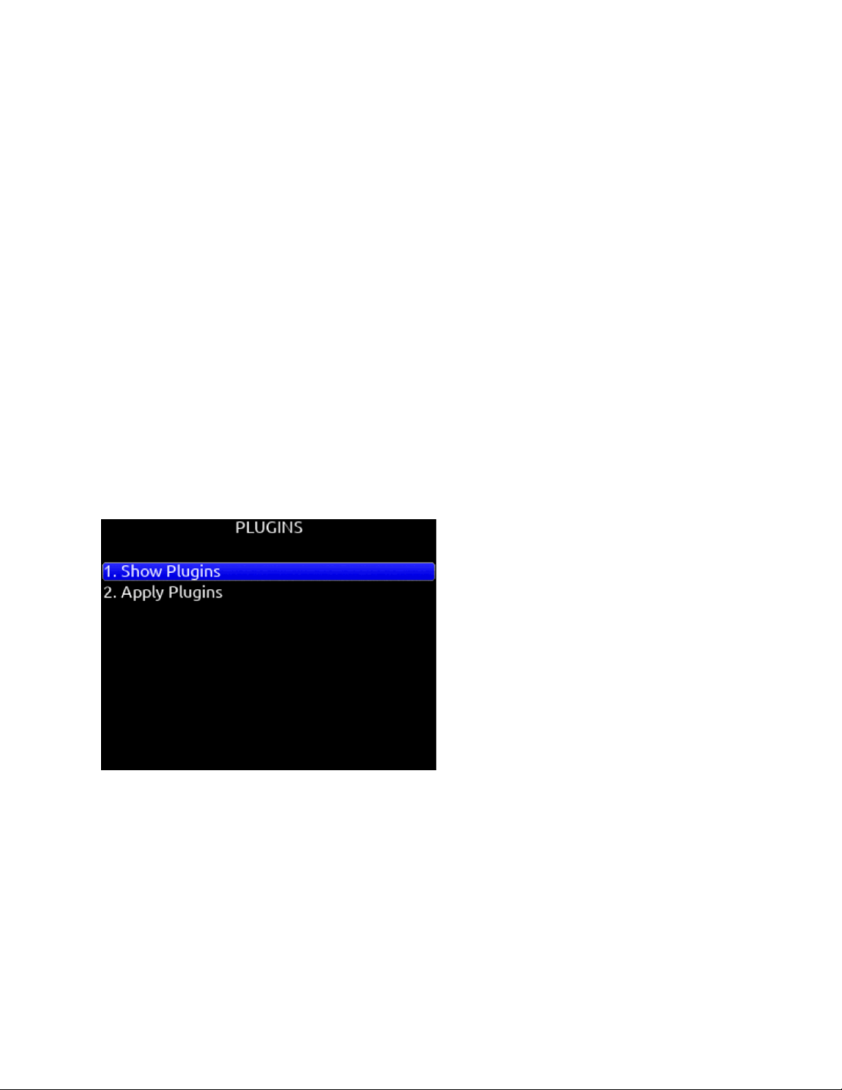
Plugins
Plugins can be purchased and downloaded from store.sounddevices.com.
Available Plugins for Scorpio
The following plugins are available for the Scorpio:
● NoiseAssist
Suppress background noise instantly on-location with the optional NoiseAssist plugin for 8-Series mixer-recorders.
Choose between 2, 4, and 8 instances that can be applied to any channel or bus!
● CEDAR sdnx
CEDAR sdnx brings CEDAR Audio Ltd.’s highly-regarded noise suppression technology to 8-Series mixer-recorders.
Choose between 2, 4, and 8 instances that can be applied to any channel or bus!
To Install a Plugin
Ensure the firmware version is compatible with the plugin.
1. Download the plugin file from the plugin store.
2. Unzip the folder and locate the license (LIC) file.
3. Place the LIC file on the root of an SD card formatted by the8-Series or place on the SSD while in file transfer mode.
4. Insert the SD card into the 8-Series.
5. Navigate to Menu>System>Plugins.
6. Enter the Plugins menu and select “Apply Plugins”. The plugin will install and the 8-Series mixer-recorder will restart.
Show Plugins
Allows you to see which Plugins have been installed on the device.
Scorpio User Guide 81

Scorpio User Guide 82
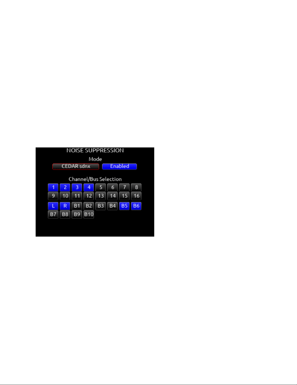
Noise Suppression Plugins
Suppress background noise instantly on-location with the optional CEDAR sdnx or Sound Devices NoiseAssist plugins for 8-Series
mixer-recorders.
Cedar sdnx
Over the last few decades, CEDAR has become synonymous with real-time, low-latency, and artifact-free audio restoration and
noise suppression. CEDAR Audio Ltd.’s sdnx brings CEDAR’s highly-regarded noise suppression technology to 8-Series
mixer-recorders. This optional plugin reduces unwanted background noises so you can better capture dialog.
CEDAR sdnx has near-zero latency and one simple control for adjusting the amount of suppression. Up to 8 instances of CEDAR
sdnx are available per mixer-recorder/device. These instances can run on any combination of isolated channels (excluding 17-32 on
Scorpio) or bus. The plugin functions at sample rates up to and including 96 kHz.
Previously, using CEDAR with an 8-Series mixer-recorder required a separate hardware unit like the CEDAR DNS 2. This
collaboration between CEDAR and Sound Devices marks the first time CEDAR technology has been available in-unit for any
portable mixer-recorder. Now, even ultra-light portable recording setups have access to CEDAR noise suppression.
CEDAR sdnx requires 8-Series firmware v7.40 or higher. Want to try before you buy? The 2-instance version of the plugin is
available as a demo on 8-Series running v7.40 or higher.
Sound Devices NoiseAssist
NoiseAssist is an advanced signal processing algorithm that reduces background noises such as traffic, generators, HVAC noise,
and more. The plugins continuously monitor background noise to give you clean audio for the entire take.
Using NoiseAssist is easy and fast - simply adjust the amount of background noise to suppress and NoiseAssist will do the rest.
Suppression happens in real time with just 1 ms of latency - no “learning” required. Depending on the plugin purchased, two-, four-,
or eight- instances of NoiseAssist can run on any combination of isolated channels (excluding 17-32) and/or any bus.
This algorithm is optimized specifically for high-end professional film and television dialog. It accurately distinguishes the desired
speech signal from background noise using proprietary advanced multi-band frequency, level, and statistical calculations.
NoiseAssist maintains the excellent frequency bandwidth of the audio channel, while effectively suppressing the background noise
and reverberation.
NoiseAssist Plugins are available for purchase at store.sounddevices.com
Try the two-instance version of NoiseAssist Plugin in demo mode (tone bursts replace audio every 10 seconds) until the NoiseAssist
Plugin license is purchased and installed. The NoiseAssist demo mode is disabled when the 8-Series is powered down.
Mode
Selects NoiseAssist or CEDAR sdnx and whether Noise Suppression is disabled* or enabled.
Scorpio User Guide 83
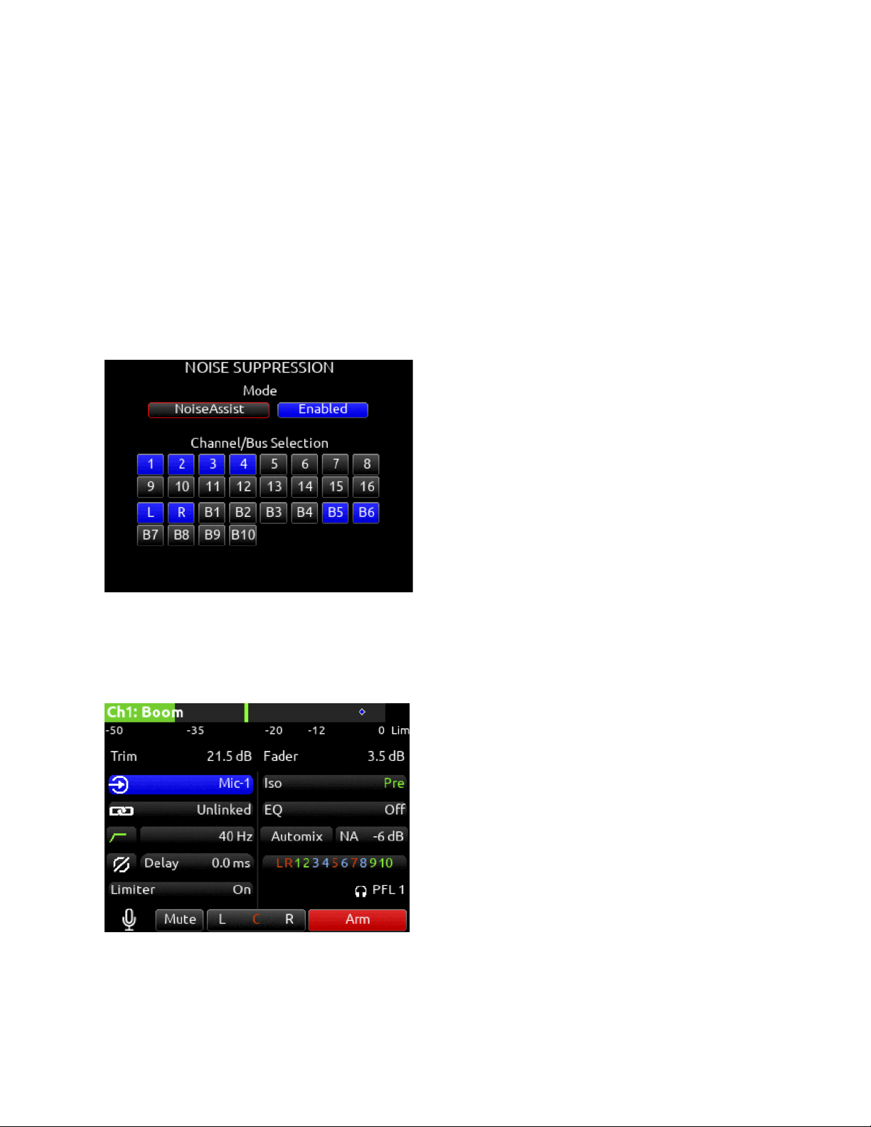
The Noise Suppression field in the channel and bus screens shows as NA when NoiseAssist is active and NX when CEDAR sdnx is
active.
Note: Set a toggle shortcut or mapped controller button to enable/disable Noise Suppression to allow you to quickly compare the
effect of it being on or off.
Channel/Bus Selection
Selects up to eight (depending on plugin installed) instances of Noise Suppression and which channels 1-16 and/or Buses it is
applied to. If the maximum number of instances are already selected, deselect one instance before selecting another.
Note: Noise Suppression only affects the mix of ISOs and return bus sources when applied to buses receiving audio from L, R, B1,
B2 buses.
Note: NoiseAssist and CEDAR sdnx cannot be used at the same time.
NoiseAssist is only available at sample rates of 48.048 kHz and less.
CEDAR sdnx is only available at sample rates of 96 kHz and less.
Adjusting Noise Suppression
In the Noise Suppression menu, ensure Noise Suppression is enabled and the required channel and/or bus is selected.
For a Channel (1-16): Enter the channel screen using the PFL toggle. Use the Select knob to scroll to and enter the
NoiseAssist (NA) or CEDAR sdnx (NX) field. Rotate the Select knob to set the amount of Noise Suppression applied to the channel.
For Bus L,R: Go to Menu>Buses and select Bus L or Bus R, whichever has been enabled for Noise Suppression. Push the */**
toggle to the right to select the NA or NX parameter and rotate the Select knob to set the amount of Noise Suppression applied to
the bus.
Scorpio User Guide 84
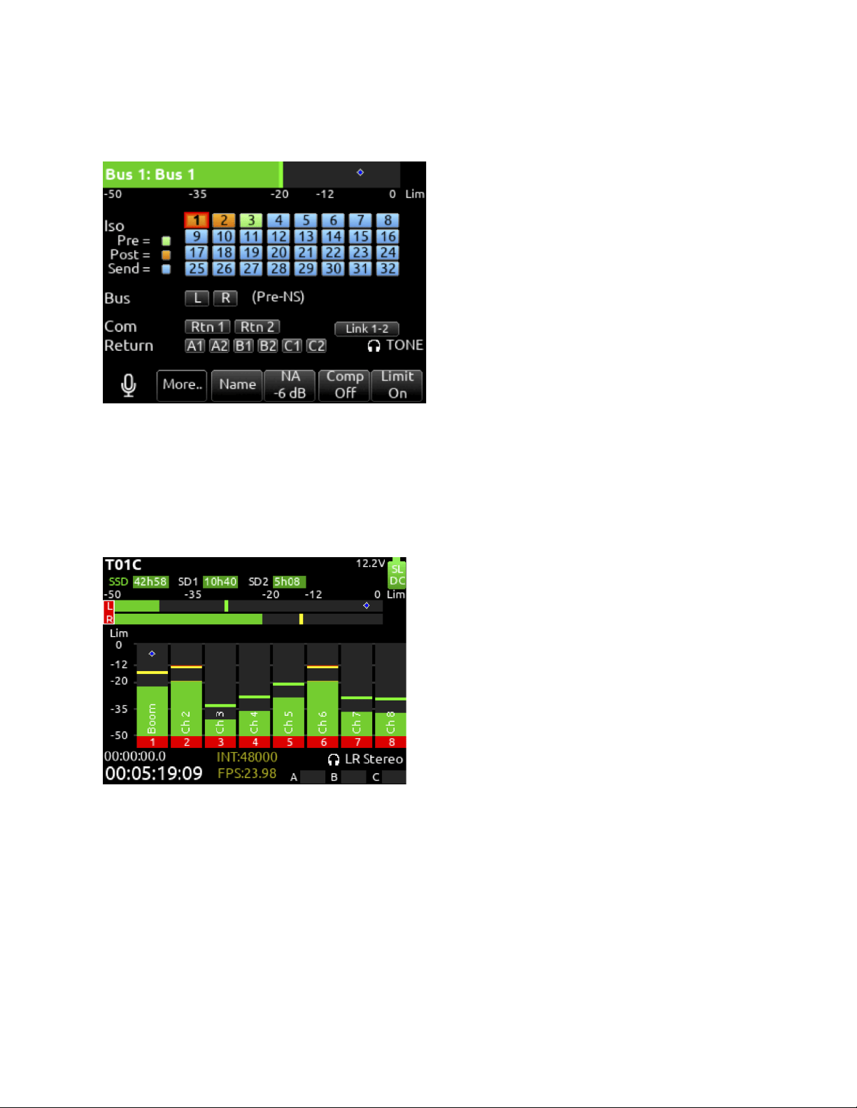
For a Bus B1-10: Go to Menu>Buses and select Bus 1-10, whichever has been enabled for Noise Suppression. Push Tone toggle to
display more options then push the */** toggle to the right to select the NA or NX parameter and rotate the Select knob to set the
amount of Noise Suppression applied to the bus.
Noise Suppression values range from 0 dB to -20 dB with 0 dB representing no noise attenuation and -20 dB being the maximum
amount of noise attenuation.
Channels or Buses enabled for Noise Suppression show a diamond in their meters. The diamond moves based on the amount of
Noise Suppression averaged across all the frequency bands that have signal in them.
The lower the diamond on the meter scale, the more the background noise is being attenuated. The diamond moves towards the top
of the scale as the audio signal changes (for example, when a mic picks up dialog) - this indicates that the Noise Suppression
algorithm is learning and adapting to the signal in real-time.
To effectively use Noise Suppression, start with the default setting of -6 dB and dial in more or less depending on your environment.
An deal setting will reduce the background noise without coloring the sound.
Note: NoiseAssist and CEDAR sdnx are not automatically linked when channels or buses are linked.
Scorpio User Guide 85
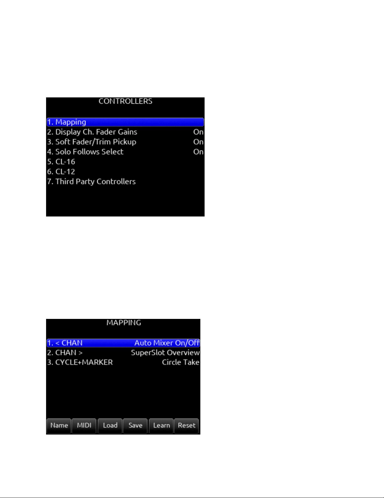
Controllers
Scorpio can be controlled from the Sound Devices CL-16 or CL-12 linear fader controllers or supported third-party external
controllers that conform to the MCU protocol.
Controllers connect via the Scorpio’s USB-A port either directly or via a USB hub.
Mapping
Selects Mapping menu. Mapping provides the ability to learn controller button presses and map them to a desired function. The
action of pressing two buttons simultaneously can also be mapped.
Note: some buttons or button combinations are reserved and cannot be mapped.
A. Name: Allows for custom naming of controller button.
B. MIDI: Toggles between the button name and MIDI code of the selected button function.
C. Load: Loads a saved button mapping preset.
D. Save: Saves a button mapping preset to any/all media. Toggle “Fav” after media selection to save.
E. Learn: Selects learn function. To use, toggle Learn and press the desired button to be learned on the controller. Once the
button has been learned, press the HP knob to scroll through the possible list of available functions (shown below) that
can be assigned and select the desired function.
F. Reset: Deletes the currently selected button mapping in the Mapping menu.
Scorpio User Guide 86

Mappable Functions
All controllers have custom-mappable buttons for performing any of the following actions on Scorpio:
Function
Action
Add Q-mark
Adds a Q-mark during record, playback, scrub or pause
Auto Mixer On/Off
Toggles the Auto Mixer on/off
Bus Mode
Bus Masters
Channel Groups Edit
Create/Edit channel groups
Channel Sends on Faders
Shortcut to put Bus sends on linear faders/toggle on/off
Channel Source Edit
Patch input to channel
Circle Take
Circle take
Com Send 1
Activates Com Send 1
Com Send 1 (Latch)
Activates Com Send 1 latching operation
Com Send 1 (Momentary)
Activates Com Send 1 momentary operation
Com Send 2
Activates Com Send 2
Com Send 2 (Latch)
Activates Com Send 2 latching operation
Com Send 2 (Momentary)
Activates Com Send 2 momentary operation
Com Rtn
Activates Com Rtn
Create Sound Report
Creates Sound Report to selected media
Current Take Notes
Edits the current takes notes
Current Take Number
Edits the current takes number
Current Take Scene Name
Edits the current takes scene name
Dante Out Edit
Shortcut to Dante Output Routing screen
Delete Q-mark
Deletes a Q-mark during record, playback, scrub or pause
EQ Mode
Spills EQ parameters over scribble strips, Fader Bank right to view last parameter. Push
and hold V-Pot 1 to toggle EQ on/off, push each band’s amplitude V-Pot to toggle on/off
each band, push each band’s Q V-Pot to toggle EQ type Shelf/Peak.
Fader Bank Left
Switches faders to left banks on connected controller
Fader Bank Right
Switches faders to right banks on connected controller
False Take
Activates False Take function
Fast Fwd
Press and hold to fast forward during playback
Fat Ch. Mode
Spills fat channel parameters across scribble strips
Fat Ch. Mode Bus
Spills fat channel bus parameters across scribble strips
Fav HP Preset
Recalls Fav HP Preset from Main Menu>Outputs>HP Presets
Fav Toggle
Emulates Fav toggle
Home
Activates Home screen and Trim knobs mode
HP Presets Menu
Shortcut to Main Menu>Outputs>HP Presets
Jog is HP
Switches Jog wheel to emulate HP knob
Scorpio User Guide 87

Jog is Select
Switches Jog wheel to emulate Select knob
Jog Wheel Press
Acts as “Select” while using jog wheel
L-ident
Identifies left channel output by varying amplitude vs. right channel with constant amplitude
LR Returns Meter
Activates the returns meter view
Menu
Emulates the Menu button
Meter
Emulates the Meter button
Mic Toggle
Emulates the Mic toggle
Mix Low Cut Mode
Activates all V-Pots to Low Cut mode on every channel. Push to reset to O Hz.
Mix Pan Mode
Activates all V-Pots to Pan mode on every channel. Push to center pan
Mix Trim Mode
Activates all V-Pots to Trim mode on every channel. Push to enter pan mode.
Nav Down
Moves the highlighted selection up one in matrix screens, emulates HP knob down in Home
screen
Nav Left
Navigates back to previous screen
Nav Right
Selects the currently highlighted selection
Nav Up
Moves the highlighted selection down one in matrix screens, emulates HP knob up In Home
screen
Next Take Notes
Edits the next takes notes
Next Take Number
Edits the next takes number
Next Take Scene name
Edits the next takes scene name
Noise Supp. Menu
Enters the Noise Suppression Menu
Noise Supp. On/Off
Toggles the noise suppression
Out Mode
Selects the output masters mode
Play
Plays the last recorded take
Play Remain Time
Selects the remaining time in the LED timecode display
Record
Starts record
Record Folder
Navigates to the record folder
Rewind
Rewinds during playback
Rtn A
Selects Rtn A toggle on/off
Rtn B
Selects Rtn B toggle on/off
Rtn Toggle
Emulates the Rtn toggle
SuperSlot Overview
Opens the SuperSlot Overview screen
Scene Inc
Brings up the Scene Inc Dialog box for incrementing Scene Name according to the setting
in Files>Scene Increment Mode
Scene Name
Brings up the Scene Name Edit virtual keyboard screen for editing the current take’s scene
during record and the next take’s scene during stop
Select
Selects the currently highlighted selection in menus and matrix screens
Slate
Toggles Slate on/off
Slate (Latch)
Toggles Slate latching operation
Scorpio User Guide 88

Slate (Momentary)
Toggles Slate momentary operation
Stop
Stops playback
SuperSlot Overview
Shortcut to SuperSlot view (when available)
Take List
Brings up the Take List
Timecode Jam
Brings up the Timecode Jam screen
Toggle Jog is Select
Toggles between Select and HP knob press
Tone
Toggles tone on/off
Tone Toggle
Emulates Tone toggle
* Toggle
Emulates * toggle
** Toggle
Emulates ** toggle
Display Ch. Fader Gains
Selects whether the fader gains are displayed in the controller’s display. [Off, On*]
Applies to CL-16 and 3rd party controllers.
Soft Fader/Trim Pickup
[Off*, On] When enabled, physical faders and trims on the 8-Series front panel, CL-16, CL-12, and some 3rd party controllers with
non-motorized faders resume gain control only when their physical position reaches the last stored gain value. This prevents sudden
jumps in gain levels when setting gains from more than one control interface.
Note: Last stored gain values are held over a power cycle and may require the adjustment of a physical fader or trim control to
pickup the last stored gain value.
Note: Soft Fader/Trim Pickup also works in conjunction with the SD-Remote. The 8-Series trim/faders pickup control only once they
have reached the last gain set in SD-Remote.
When Soft Fader/Trim Pickup is Off and a controller is connected, the 8-Series front panel controls are disabled unless controlled by
SD-Remote. Use SD-Remote Hide Faders function to prevent SD-Remote changing fader gains accidentally.
Note: When a non-motorized fader controller and SD-Remote are both used at the same time, the controller will not soft pickup fader
or trim control.
Solo Follows Select
Selects whether solo (PFL) mode is engaged on a channel when pressing “Select” from the controller [Off, On*]. Applies to
supported 3rd party controllers and CL-16.
CL-16
Selects CL-16 menu.
1. LED Brightness: 5-100% in increments of 5% (100% is default)
2. LCD Brightness: 5-100% in increments of 5% (100% is default)
3. Long Button Press: 300-1000 ms in increments of 5 ms (500 ms is default)
4. Bank Disable: On or Off (off is default)
5. GPIO Configuration: Opens menu to display GPIO_1 - GPIO_8 (see below for options and details)
6. Channel Colors: Opens a menu to assign background colors to LCD channel strips 1-32.
7. Group Colors: Opens menu to assign Group 1-4 Color (Defaults: 1=Yellow, 2=Orange, 3=Light Blue, 4=Light Green).
Color options: Yellow, Orange, Light Blue, Light Green, Green, Light Brown, Brown, Violet, Pink.
8. Gray Meters: Off or When Disarmed
CL-16 Operation is covered in the CL-16 User Guide.
Scorpio User Guide 89
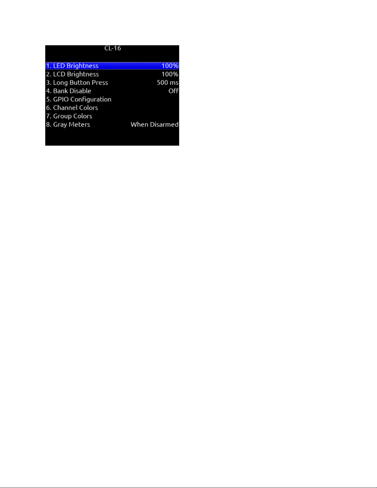
CL-16 GPIO (General Purpose Input/Output)
The 10-pin Phoenix connector labeled Remote provides eight GPIO ports. These can be configured as simple contact-closure
inputs, and to drive low current draw components such as LEDs and logic-controlled powered relays.
CL-16 Remote Pin Functions
Ground (-): for triggering logic-low connections.
1 - 8: Configurable as inputs or outputs, activate high or low, and assigned a function.
+5 V DC: for triggering logic high connections.
Active High inputs trigger when +5V is applied.
Active Low inputs trigger when ground is applied.
Active High outputs go to 5 V when the mapped function is active.
Active Low outputs go to ground when the mapped function is active.
The GPIO lines can supply or sink 10 mA through the series 100 ohm internal resistance. This is not enough to directly drive relays
but is enough for driving logic-controlled powered relays.
Pin 10 of the connector supplies 1A at 5V.
GPIO Outputs can be used to drive LEDs with a proper series resistor. Resistor values vary from LED to LED, 470 ohms is a good
starting point.
Although the CL-16 has protection against ESD (static electricity), highly inductive loads (like relays, bells etc) may require extra
diode protection to protect against inductive voltage spikes. Make sure to protect the CL-16 with an anti-parallel diode across the coil
of what is being driven.
CL-16 GPIO Configuration Menu
Input/Output
Toggle on Mic/Tone Switch
Active High/Active Low
Toggle on */** Switch
Defaults
GPIO_1=Record, 2=Play, 3=Stop, 4=None, 5=None, 6=Record, 7=Play, 8=Stop
Available Options
None, Auto Mixer On/Off, Bus Mode, Channel Groups Edit, Channel Sends on Faders, Channel Source Edit, Circle Take, Com Send
1, Com Send 1 (Latch), Com Send 1 (Momentary), Com Send 2, Com Send 2 (Latch), Com Send 2 (Momentary), Com Rtn 1, Com
Rtn 2, Create Sound Report, Dante Out Edit, Edit Scene Name, Edit Take Notes, Edit Take Number, EQ Mode, Fader Bank Left,
Fader Bank Right, False Take, Fast Fwd, Fat Ch Mode, Fat Ch Mode Bus, Fav HP Preset, Fav Toggle, Home, HP Presets Menu,
Jog Is HP, Jog Is Select, Jog Wheel Press, L-Ident, LR Returns Meter, Menu, Meter, Mic Toggle, Mix Low Cut Mode, Mix Pan Mode,
Mix Trim Mode, Nav Down, Nav Left, Nav Right, Nav Up, Out Mode, Play, Play Remain Time, Record, Rewind, Rtn A, Rtn B, Rtn C,
Scorpio User Guide 90
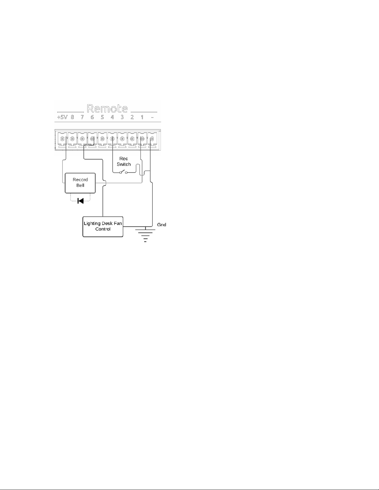
Rtn Toggle, SL-6 Receiver Overview, Scene Inc, Scene Name, Select, Slate, Slate (Latch), Slate (Momentary), Stop, Take List, Take
Notes Edit, Take Number Edit, Timecode Jam, Toggle Jog is Select, Tone, Tone Toggle, *Toggle, **Toggle
CL-16 GPIO Wiring Diagram Example
In this example, an external contact-closure switch starts recording and the GPIO outputs are used to sound a record bell and turn
off a lighting fan.
Record bell:
GPIO pin 1 settings:-
● Output
● Active Low
● Record
Record contact-closure switch:
GPIO pin 4 settings:
● Input
● Active Low
● Record
Lighting fan control (Fan requires +5 V on its trigger input to turn off):
GPIO pin 6 settings:
● Output
● Active High
● Record
CL-12
Selects the CL-12 menu. The CL-12 is a 12 channel linear fader controller with control over fader gain, PFL, Arm, EQ, buses,
outputs, coms, transport, metadata, and more. For detailed setup and operational information, please refer to the CL-12 User Guide.
Note that the CL-12 Linear Fader Controller cannot be used with another controller.
CL-12 menu settings:
1. L-X2 Level Controls: sets whether the L-X2 pots control bus level or output level or whether they are disabled altogether.
2. L-X2 Metering: sets whether the L-X2 meters display bus or output levels.
3. L-X2 Routing: sets whether L-X2 routing is to buses L-X2 or outputs L-X2.
4. LED Brightness: sets CL-12 LED brightness
5. SEL Follows PFL: selects whether a channel is automatically selected when its PFL is engaged.
Scorpio User Guide 91
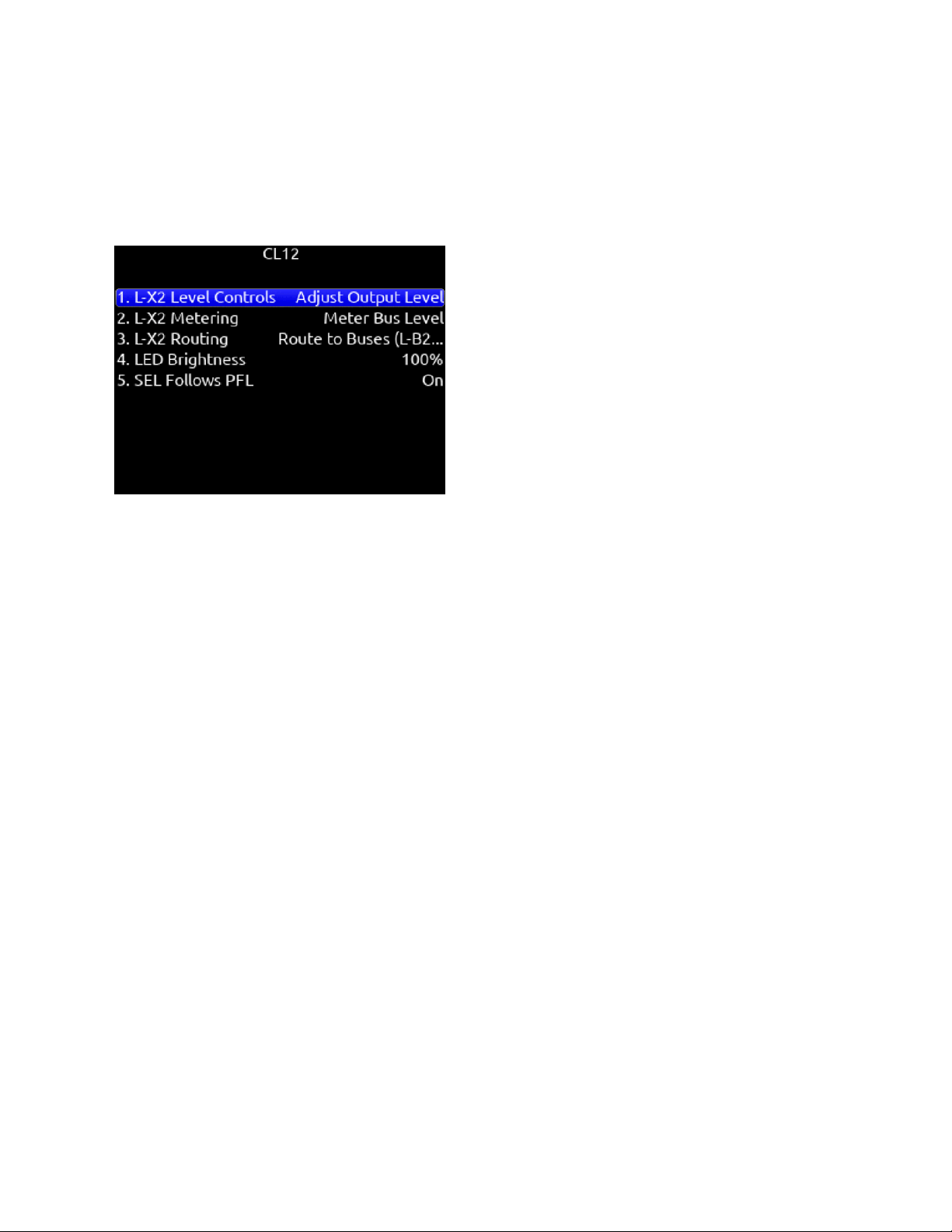
Tips: When CL-12 is connected to Scorpio, trim gains are controlled from Scorpio.
Slate mic can be toggled on/off by pressing both COM 1 and COM 2 simultaneously.
When adjusting EQ from the CL-12, the EQ values are displayed at the bottom of the Scorpio meter view.
A USB-A to USB-A cable is required to connect the CL-12.
Pressing stop while in stop will toggle between editing the next take and current take’s scene, take and notes metadata.
Third Party Controllers
1. Require Shift for Arm: When selected, “Shift” on external control surface must be pressed simultaneously with “Rec” to
arm tracks. [Off*, On]. Applies to supported 3rd party controllers only.
2. Require Shift for Mute: When selected, “Shift” on external control surface must be pressed simultaneously with “Mute” to
mute channels, buses, and outputs. Applies to supported 3rd party controllers only.
3. Main Fader: Sets which bus or output a third party controller’s main fader controls.
4. Multiple Controllers: When multiple controllers are simultaneously connected to the Scorpio via a USB hub, sets whether
they operate in Spill or Individual mode.
a. SPILL: In Spill Mode, all MCU controllers connected to the Scorpio work as one big control surface. All
controllers operate in the same mode (e.g. Mix Mode, Bus Mode, Output Mode etc), all channel strips join into a
single fader bank spilled across all controllers, and all controlled parameters spill across all available channel
strips. For example, a setup with two 8-fader controllers spills faders 1-8 to controller 1 and faders 9-16 to
controller 2. The Bank Right button banks faders 17-24 to controller 1 and faders 25-32 to controller 2. The USB
Hub port number determines which controller is Controller 1 and which is Controller 2. Controller 1 must be
connected to a lower USB port number than Controller 2. On most hubs, the USB port numbering is not marked
in which case, try the various ports to determine the hub’s USB port numbering.
b. INDIVIDUAL: In Individual Mode, each controller behaves independently with its own operating mode and fader
bank. For example, this allows using one controller for the main channel mix in Mix Mode and a separate
controller for setting up IFB feeds in Bus Mode or Bus Sends on Faders Mode. A third controller could be used
for output control in Output mode.
Control Modes
A Control Mode determines the function of a controller’s faders, VPots, and other buttons.
The VPots are the multi-function encoder knobs positioned above each channel’s fader.
Mix Trim Mode (Home). For mixing channels to the main LR bus. Switches faders to channel faders and VPots to channel trims.
Mutes and Solos buttons are channel mutes and solos respectively.
Fat Channel Mode. For editing various channel parameters including Trim, Pan, Source, Delay, Phase, Limiter, HPF, EQ, and Bus
Sends.
Mix Pan Mode. For adjusting channel pans by rotating the VPots. Press a VPot to set pan to center. Faders, mutes and solos
continue to control the channel mix, mutes and solos.
Scorpio User Guide 92

Mix Low Cut Mode. For adjusting channel low cut frequency by rotating the VPots. Press a VPot to toggle Low Cut On/Off. Faders,
mutes and solos continue to control the channel mix, mutes and solos.
Bus Mode. For adjusting Bus levels B1-B10, L,R. Switches faders to Bus faders. Mutes and Solos buttons are Bus mutes and solos
respectively.
Bus Sends-on-Faders Mode. Faders are channel sends to the selected bus. Ideal for creating different IFB feeds/mixes.
Channel Bus Sends Mode. VPots adjust a channel’s send gains to each bus. Press VPot to toggle between Off, Pre, Post and
Send. Rotate VPot to adjust bus send gain. Use the Select buttons to select which channel’s send gains to adjust.
Output Mode. For adjusting Output levels X1-X10, L,R. Switches faders to Output level controls. Mute buttons are output mutes.
EQ Mode. For adjusting channel EQ using the VPots. Use the Select buttons to select which channel’s EQ to adjust. Faders
continue to control the channel mix.
Supported Third-Party Controllers
Scorpio supports a variety of third-party external controllers that conform to the MCU protocol. Multiple controllers may be connected
simultaneously for extended control. MCU-based controllers not in the list below, may or may not work correctly.
SONOSAX SX-LC8+
Eight channel compact fader bank with faders and channel selects for channels 1-8 plus controls for slate mic, record, and stop. The
Mic, Rec, and Stop buttons are mappable to other functions using the Mapping menu.
Ensure the Sonosax is set to USB Midi mode
1. Press and hold buttons 6 + 7 + 8 and connect the USB cable to the 8-Series USB-A port. The mode change is confirmed
by a blinking REC
2. Reboot the 8-Series.
Icon Platform M+ and D2 Display
Eight channel fader bank with control over gain, bus, sends, coms, trim and pan. Dedicated Select, Mute, Solo and Arm buttons for
each channel. Bank switch to access Scorpio channels 1-32 in four banks of eight channels. Icon M+ Operation is covered in the
Icon M+ User Guide: https://cdn.sounddevices.com/wp-content/uploads/2019/05/Icon-User-Guide.pdf
Icon Platform X+
Eight channel expansion fader bank with single assignable knob and Select, Mute, Solo and Arm buttons.
Icon Platform B+
Assignable illuminated 50 pad button surface. Allows a user to custom map up to 50 functions.
Connects via USB-A cable, not mini DIN.
Behringer X-Touch
Eight channel trim and fader panel with master volume and additional mappable buttons. Bank switch to access Scorpio channels
1-32 in four banks of eight channels.
Mackie MCU Pro
Eight channel trim and fader panel with master volume and additional mappable buttons. Bank switch to access Scorpio channels
1-32 in four banks of eight channels.
Studiologic SL-MixFace
Compact eight-channel trim and fader panel with master fader, transport control, and additional mappable buttons. Bank switch to
access Scorpio channels 1-32 in four banks of eight channels. Note: The Soft Fader/Trim Pickup function does not pickup trim and
fader values when going between banks and control modes - adjusting trim or fader after moving from one bank or control mode to
another will result in sudden audio level changes.
● Ensure the SL-MixFace is set to REAPER DAW mode.
● The 4 mode buttons (Rec, Mute, Solo, Select) determine the function of the button at the bottom of each channel strip.
● The pots at the top of each channel strip are always mapped to the channel trim gain even though the SL-MixFace top
panel marking shows ‘PAN’.
● To pause playback, press the stop/playback button. To stop playback, press and hold the stop/playback button.
Note: Since, the SL-MixFace does not have displays for each channel like the CL-16, Waves Fit, Icon, Behringer etc, be aware that
there is no indication of what the current Control Mode or Bank is. The pots at the top of each channel change their function based
on Control Mode and Bank.
Scorpio User Guide 93

Waves MidiPlus Fit
Sixteen channel trim and fader panel with main fader and additional mappable buttons. Bank switch to access Scorpio channels
1-32 in two banks of sixteen channels. Note that the Waves MidiPlus Fit must be running firmware v1.1.3 or later and set to MCU
mode. To enter MCU mode, hold down the ‘Solo’ button of channel 1 and the ‘2’ button of channel 2 simultaneously while turning on
the FIT. Refer to the ‘Waves MidiPlus Fit Controller for the 8-Series - User Reference’ for more information.
Scorpio User Guide 94
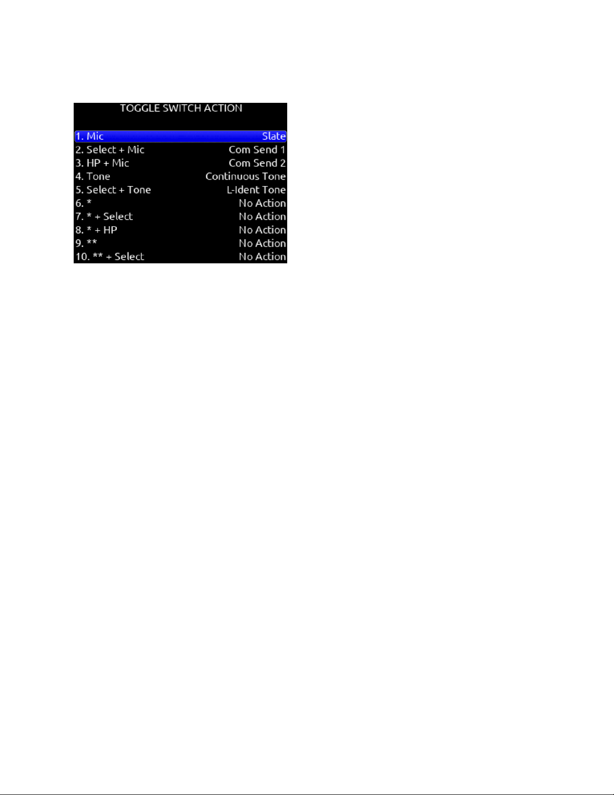
Toggle Switch Action
Select + Mic, HP + Mic, Mic
Selects Slate, Slate (Latch), Slate (Moment), Com Send 1, Com Send 1 (Latch), Com Send 1 (Moment), Com Send 2, Com Send 2
(Latch), Com Send 2 (Moment), Ch 13 Trim/PFL (latch), Ch 14 Trim/PFL (latch), Ch 13 Fader /PFL (latch), Ch 14 Fader/PFL (latch),
Add Q-mark, Delete Q-mark, Create Sound Report, Record Folder, or No Action.
Select + Tone, Tone
Selects Continuous Tone, L-ident Tone Add Q-mark, Delete Q-mark, Create Sound Report, Record Folder, or No Action.
*/**
[Jam Menu, Jam A20-Mini Menu, Circle Take, Slate, Slate (Latch), Slate (Moment), Com Send, Com Send Latch, Com Send
Moment, Rtn A, Rtn B, Com Rtn, Automixer On/Off, Noise Suppression On/Off, Take List, Take Notes, Take Number,
Ch 13 Trim/PFL (latch), Ch 14 Trim/PFL (latch), Ch 13 Fader /PFL (latch), Ch 14 Fader/PFL (latch), Add Q-mark, Delete Q-mark,
Create Sound Report, Record Folder, No Action,
Next Scene Name (Edits the next take’s scene name),
Current Scene Name (Edits the current take’s scene name and applies that to the next take),
New Scene Name (Creates a new scene name, adds it to the scene name entry list and in record, applies it to the currently
recording take and next take. In stop, it is applied only to the next take)]
* + Select
[Ch 13 Trim/PFL (Moment), No Action]
* + HP
[Ch 14 Trim/PFL (Moment), No Action]
** + Select
[Ch 13 Fader/PFL (Moment), No Action]
** + HP
[Ch 14 Fader/PFL (Moment), No Action]
Select + Rtn/HP + Rtn/Rtn
[Rtn A, Rtn B, Rtn C, Com Rtn 1, Com Rtn 2, Fav HP, Ch 13 Trim/PFL (latch), Ch 14 Trim/PFL (latch), Ch 13 Fader /PFL (latch), Ch
14 Fader/PFL (latch), Add Q-mark, Delete Q-mark, Create Sound Report, Record Folder, No Action]
Select + Fav, Fav + HP, Fav
[Rtn A, Rtn B, Rtn C, Com Rtn 1, Com Rtn 2, Fav HP, Ch 13 Trim/PFL (latch), Ch 14 Trim/PFL (latch), Ch 13 Fader /PFL (latch), Ch
14 Fader/PFL (latch), Add Q-mark, Delete Q-mark, Create Sound Report, Record Folder, No Action]
Scorpio User Guide 95
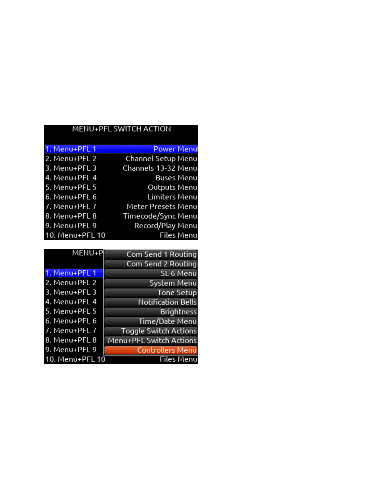
Menu + PFL Switch Action
Menu+PFL Switch [1-12]
[Power Menu. Channel Setup Menu, Channel Groupings, Channels 13-32 Menu, Buses Menu, Outputs Menu, (LR, X1-X10 Output
Routing), L Out, R Out, X1 Out, X2 Out, X3 Out, X4 Out, X5 Out, X6 Out, X7 Out, X8 Out, X9 Out, X10 out, 10-Pin Out, Dante
Output Routing, Dante Out 1-32, HP Presets, Limiters Menu, Meter Presets Menu, Meter Preset 1-12, Timecode/Sync Menu, Jam
Timecode, Set Generator TC, Set Generator Ubits, Lemo Options, Record/Play Menu, Track To Media, Files Menu, File List, Take
List, File Name Format, Sound Report Info, Slate/Coms/Returns Menu, Slate Routing, Com Send 1 Routing, Com Send 2 Routing,
SL-6 Menu, System Menu, Tone Setup, Notification Bells, Brightness, Time/Date Menu, Toggle Switch Action, Menu+PFL Switch
Actions, Controllers Menu, Automixer On/Off, Noise Suppression menu, Edit Scene Name, Take Number, Take Notes, Scene Name,
Record Folder, SuperSlot Overview]
Scorpio User Guide 96
Front Panel Shortcuts
The Menu + PFL Shortcuts are set by default. They can be customized by going to System > Menu + PFL Switch Action.
Menu + PFL Shortcuts
Action
Menu + PFL 1
Power Menu
Menu + PFL 2
Channel Setup Menu
Menu + PFL 3
Channels 13-32
Menu + PFL 4
Buses Menu
Menu + PFL 5
Outputs Menu
Menu + PFL 6
Limiters Menu
Menu + PFL 7
Automixer Menu
Menu + PFL 8
Meters Preset Menu
Menu + PFL 9
Timecode/Sync Menu
Menu + PFL 10
Record/Play Menu
Menu + PFL 11
Files Menu
Menu + PFL 12
Slate/Coms/Returns Menu
Toggle Switch Shortcuts
Action
Mic Toggle
As defined in the System/Toggle Switch Action menu. Default: Slate
Sel + Mic Toggle
As defined in the System/Toggle Switch Action menu. Default: Com Send 1
*/** Toggle
As defined in the System/Toggle Switch Action menu. Default: No Action
Rtn Toggle
As defined in the System/Toggle Switch Action menu. Default: Rtn A
Sel + Rtn Toggle
As defined in the System/Toggle Switch Action menu. Default: Rtn B
HP + Rtn Toggle
As defined in the System/Toggle Switch Action menu. Default: Rtn C
Fav Toggle
As defined in the System/Toggle Switch Action menu. Default: Fav HP
Sel + Fav Toggle
As defined in the System/Toggle Switch Action menu. Default: Com Rtn 1
HP + Fav Toggle
As defined in the System/Toggle Switch Action menu. Default: Com Rtn 2
Scorpio User Guide 97

Other Shortcuts
Action
Channel screen, then hold PFL for >1 sec
Edits Channel (Track) Name
Meter + Rotate HP knob
Zooms meter scale
Meter + Rotate Select knob
Adjusts LCD brightness
Meter +Select or Select +Meter
Arm or disarm Selected track.
Meter + HP press
Accesses SuperSlot menu
HP + PFL 1-12
Selects HP Preset 1-12
Sel + PFL 1-12
Selects Bus 1-10, L,R
Meter + PFL 1-12
Selects Meter Preset 1-12
* Toggle + PFL 1-12
Selects Channel Screen/PFL 13-24
** Toggle + PFL 1-8
Selects Channel Screen/PFL 25-32
HP + Left on Transport Control
False Take
Sel + Fav Toggle
As defined in the System/Toggle Switch Action menu. Default: Com Rtn 1
HP + Fav Toggle
As defined in the System/Toggle Switch Action menu. Default: Com Rtn 2
Sel + Tone (hold)
L-Ident Tone
HP + Transport Control Right
Scene Increment
Sel + Transport Control Right
Add Q-mark
Sel + Transport Control Left
Delete Q-mark
Scorpio User Guide 98

USB Keyboard
A USB keyboard may be connected to the Scorpio via the USB-A port. The keyboard may be used for metadata entry as well as the
following shortcuts:
Keystroke
Description
F1
Enters Main Menu
F2
Enters Take List
F3
Toggles Meter view
F5
Emulates Mic toggle
F6
Emulates Tone toggle
F7
Emulates * toggle
F8
Emulates ** toggle
F9
Emulates Rtn toggle
F10
Emulates Fav toggle
F12
Returns to LR, 1-8 Meter View
1,2,3 ... 0
Enters Channel Screens 1-10 respectively
Ctrl+1,2,3 ... 6
Enters Channel Screens 11-16 respectively
Ctrl+R
Record
Ctrl+S
Stop
Space Bar
Play/Pause
Up arrow
Emulates HP knob rotating clockwise on most screens, except channel screens where it emulates the Sel knob
rotating clockwise.
Channel screen and matrix screens: navigates up.
HP vol in home screen, row selection in menus, parameter adjust.
Down arrow
Emulates HP knob rotating counterclockwise in most screens except channel screens where it emulates the Sel
knob rotating counterclockwise
Channel screen and matrix screens: navigates down
HP vol in home screen, row selection in menus, parameter adjust
Enter
Home Screen: Emulates HP knob press i.e. HP Monitor Source Select List
Menu screens: Emulates HP knob press i.e. Activates selection
Channel screens: Emulates HP knob press
Virtual Keyboard: OK
Ctrl+Up arrow
Emulates Sel knob rotating clockwise
Ctrl+Down
arrow
Emulates Sel knob rotating counterclockwise
Ctrl+Enter
Emulates Sel knob press
Ctrl+P
Screenshot of current screen
Scorpio User Guide 99

X-Keys® Programmable Keypads, Sticks & Keyboards
X-keys include a variety of compact, tactile input devices that can be programmed to emulate USB keyboard commands. Their
various buttons and tactile controls are programmed via P.I. Engineering’s MacroWorks Windows software. When mapped as
individual commands or as macro commands to Scorpio’s USB Keyboard shortcuts listed above, they offer quick-access to many
functions including
Record, Stop, Play, and many more.
To use with Scorpio, the X-Keys device must be connected to the USB-A port.
Please visit P.I. Engineering’s website for more information.
Scorpio User Guide 100
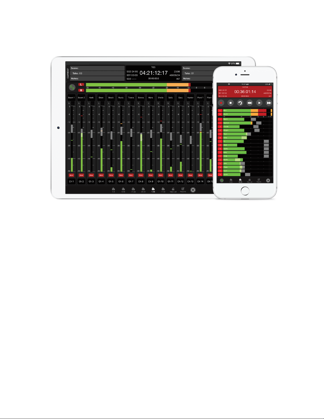
SD-Remote
SD-Remote is a mobile device application designed to pair with the Scorpio. SD-Remote is available for Android tablets and phones
in the Google Play Store or as an APK from www.sounddevices.com, and for iPhone and iPad in the App Store. An Android tablet
can be hardwired to the Scorpio via USB or wirelessly connected via Bluetooth LE. An Android phone, iPhone, or iPad wirelessly
connects to the Scorpio via Bluetooth LE. SD-Remote offers control and display parameters, including the following:
1. Channel, Bus, and Output Meters
2. Channel, Bus, and Output Names
3. Channel, Bus, and Output Source selection
4. Channel, Bus, and Output Mutes
5. Channel and Bus Solos
6. Channel and Bus Record Arm/Disarm
7. Channel Trim Gains, Fader Gains, and Pans
8. Bus and Output Faders
9. Channel, Bus, and Output Linking
10. Channel and Output Delay
11. Channel HPF, Iso, Phase, Limiter
12. Transport-dependant Output Muting
13. Record, Stop, Play, FFWD, REW
14. False Take and Circle Take
15. Take List and Metadata Editing
16. Timecode
17. Reports
18. File Transfer
First download and install the SD-Remote app from the Google Play Store or App Store.
SD-Remote requires the following minimum operating systems:
Scorpio User Guide 101

● iPad running iOS 12 or iPadOS 13+
● iPhone running iOS 12+
● Android tablets require Android 6 Marshmallow for USB connection. The device needs to support MIDI and BLE in order
to operate.
● Android phones and tablets require Android 7 Nougat when connecting via Bluetooth LE. The device needs to support
MIDI and BLE in order to operate
Note: It is recommended to close the SD-Remote app before powering down the 8-Series. This will help prevent the SD-Remote app
not connecting after the next boot up. Should SD-Remote not connect to the 8-Series, FULLY close then restart the app.
USB Setup Procedure for Android Tablets
1. Connect Android tablet to the 8-Series Mixer-Recorder via USB-A port.
2. Open the SD-Remote app, access Settings [gear icon], and choose to connect via USB.
3. On the Android tablet, open the quick settings drop down menu.
4. Touch “USB Android System” twice to open “Use USB to” dialog box.
5. Touch “Connect a MIDI device.”
“No USB Connection” popup will appear when SD-Remote does not detect presence of an 8-Series Mixer-Recorder
Bluetooth Setup Procedure for Android
1. On the 8-Series Mixer-Recorder, set Bluetooth to On in the System>Bluetooth menu.
2. Open the SD-Remote app, access the settings tab, and choose “Connect via Bluetooth”.
3. Access any Metering tab and touch the Sound Devices logo button to display a list of 8-Series devices that can be
connected to via Bluetooth. When the Devices Found list is shown, Bluetooth connection to the currently selected device
is stopped.
4. Connect to a specific 8-Series device by touching the Bluetooth button next to its serial number. ‘Connecting…’ is
displayed. Wait for connection to take place. When connection is successful, the SD-Remote meter view is displayed.
“No Bluetooth Connection” popup will appear when SD-Remote does not detect presence of the selected 8-Series device.
For optimal Bluetooth LE connection, the Sound Devices XL-ANT2.4 Antenna must be fitted to the SMA port of the 8-Series device.
Scorpio User Guide 102
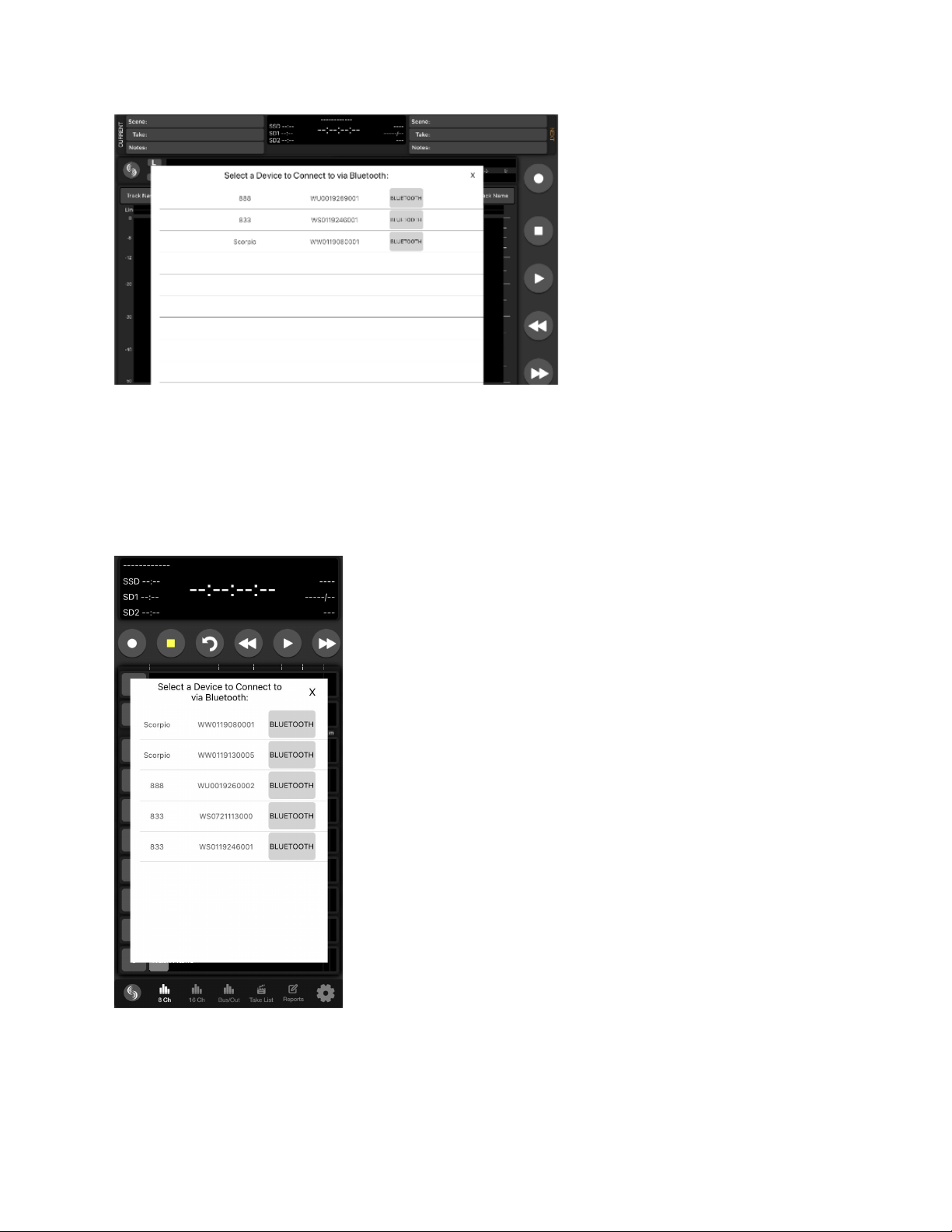
Bluetooth Setup Procedure for iPad and iPhone
1. On the 8-Series Mixer-Recorder, set System>Bluetooth to On.
2. Open the SD-Remote app and touch the Sound Devices logo button to display a list of 8-Series devices within Bluetooth
LE range. When the Devices Found list is displayed, Bluetooth LE disconnects from the previously connected 8-Series
Mixer-Recorder.
3. Connect to a specific 8-Series device by touching the serial number. ‘Connecting...’ is displayed. When connection is
successful, the SD-Remote meter view is displayed.
“No Bluetooth Connection” popup will appear when SD-Remote does not detect presence of the selected 8-Series device.
For optimal Bluetooth LE connection, the Sound Devices XL-ANT2.4 Antenna must be fitted to the SMA port of the 8-Series device.
Scorpio User Guide 103
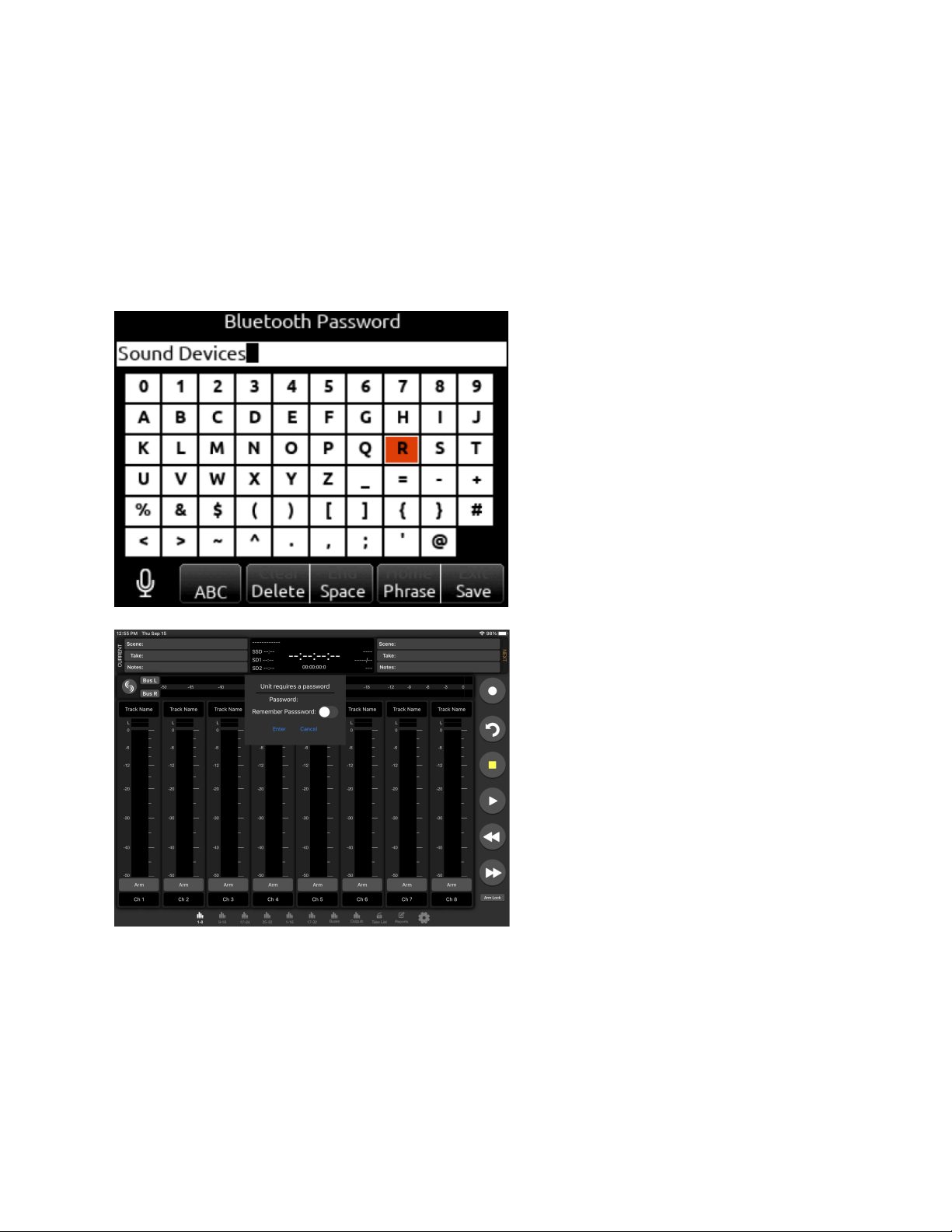
Setting a Password
To prevent unauthorized access to the 8-Series Mixer-Recorder via Bluetooth LE:
1. Navigate to System-Bluetooth-Set Password.
2. Create a password using the on-screen keyboard.
3. Use the Fav toggle to save the password.
4. Press “Ok” in the “Set New Password” dialog box.
5. Connect your tablet via SD-Remote to the 8-Series device as described above.
6. Enter the password and press “Enter” to allow connection.
7. Toggle “Remember Password” to allow the mobile device to connect without reentering password.
To Remove A Password
1. In the 8-Series menu, navigate to System-Bluetooth-Clear Password.
2. Press “Ok” in the “Clear existing password” dialog box
Scorpio User Guide 104
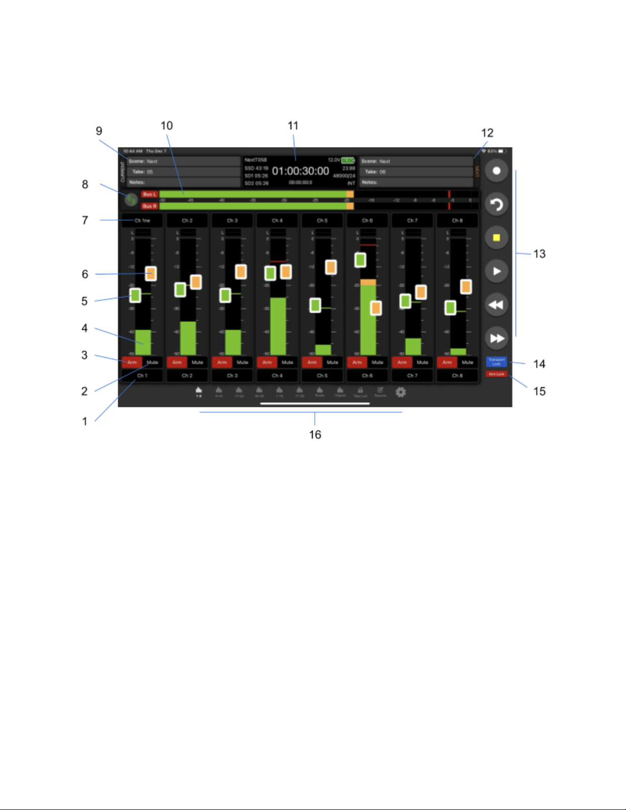
Channel Meters View
Tablet
1. Fat Channel Screen Access
2. Mute
3. Track Arm
4. Channel Meter
5. Channel Trim
6. Channel Fader
7. Channel Name
8. Device Connection
9. Current Take Metadata
10. Left & Right Mix Meters
11. Information Window
12. Next Take Metadata
13. Transport Bar
14. Transport Lock
15. Arm Lock
16. Navigation Bar
Scorpio User Guide 105
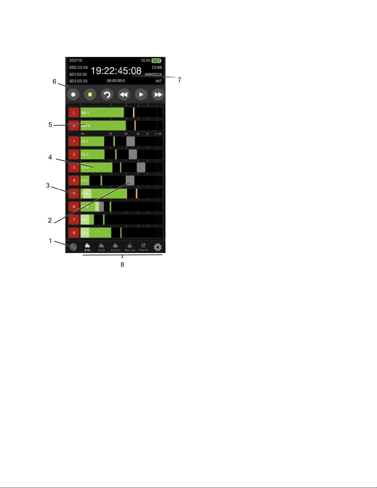
Phone
1. Device Connection
2. Channel Fader
3. Track Arm
4. Channel Meter & Channel screen Access
5. Left & Right Meters
6. Transport Bar
7. Information Window
8. Navigation Bar
Device Connection
Touch the Sound Devices insignia to view a list of available 8-Series Mixer-Recorders to connect via Bluetooth or USB. If already
connected to a device, a ‘Break Connection’ popup will appear to prevent accidental disconnection.
Information Window
Displays current take name, power source icon with remaining voltage (remaining percentage and time with Smart Batteries),
timecode, absolute time, remaining time of SSD, SD1, and SD2, Timecode frames per second, sample rate and bit depth, and sync
source. Display turns red in record and green during playback.
Navigation Bar
Allows quick access to various meter views, Take List, Sound Reports, and Settings. Tablet views allow for quick access to all
available meter screens. Phone view allows selection of 8 or 16-Channel Metering, Bus Metering, and Output Metering. Swipe up on
the channel meters to view the next bank of channel meters. Swipe up or down on Bus/Out meters view to switch view between bus
meters and output meters.
Transport Bar
Record, Stop, False Takes, Play, Rewind, and Fast Forward buttons.
Scorpio User Guide 106

Current Take Metadata (Tablet)
Displays and allows for editing of Current Take Scene, Take, and Notes. This information is also available in the Take List. Phone
views do not have access to this field on Meters view.
Next Take Metadata (Tablet)
Displays and allows for editing of Next Take Scene, Take, and Notes. This information is also available in the Take List. Phone views
do not have access to this field on Meters view.
Left & Right Mix Meters
Displays audio activity and arm status on the Left and Right Mix Bus.
Channel Name (Tablet)
Touch to edit the channel’s name. Blue fill indicates the channel is muted.
Channel Name (Phone)
Displays the channel’s name. The name can be edited from the Fat Channel Screen. Blue fill indicates the channel is muted.
Fat Channel Screen Access (Tablet)
Touch to access the channel’s Fat Channel screen. Yellow fill indicates the channel is PFL’d.
Channel Meter & Fat Channel Screen Access (Phone)
Displays the channel’s audio activity, touch the meter to access the Fat Channel Screen. A white border around the meter indicates
the channel is PFL’d.
Channel Trim (Tablet)
Touch and drag to adjust a channel’s trim gain. On a tablet, the channel name cell above the meter displays the gain dB value as the
trim is adjusted. To prevent accidental trim gain control, hide the trims by setting Hide Channel Trims to On in the Settings tab.
Channel Fader
Touch and drag to adjust a channel’s fader gain. On a tablet, the channel name cell above the meter displays the gain dB value as
the fader is adjusted. To prevent accidental fader control, hide the faders by setting Hide Channel Faders to On in the Settings tab.
Track Arms
Touch to arm/disarm channels. To arm/disarm multiple channels during record, touch and hold one arm button, then toggle others. A
new split take will only be created once the held arm button is released.
Transport lock (Tablet)
To prevent accidental transport commands, enable the Transport Lock button.
Arm lock (Tablet)
To prevent accidental arming or disarming, enable the Arm Lock button.
Fat Channel Screen
From the Fat Channel screen, view a channel’s audio activity, arm/disarm the isolated track for recording, edit the track name, set
trim gains, fader gains, pan, mute, PFL, channel source, HPF, Iso, delay, phase, limiter, and linking. Tablet views allow for direct
access to other Fat Channel screens via the tabs on the bottom of the screen.
Scorpio User Guide 107
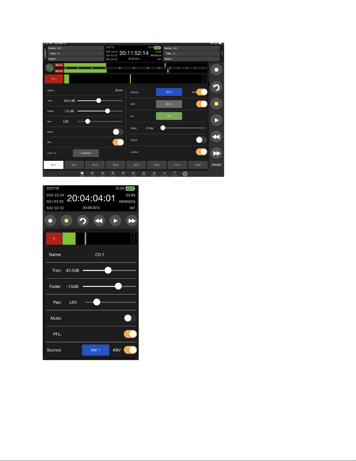
Scorpio User Guide 108
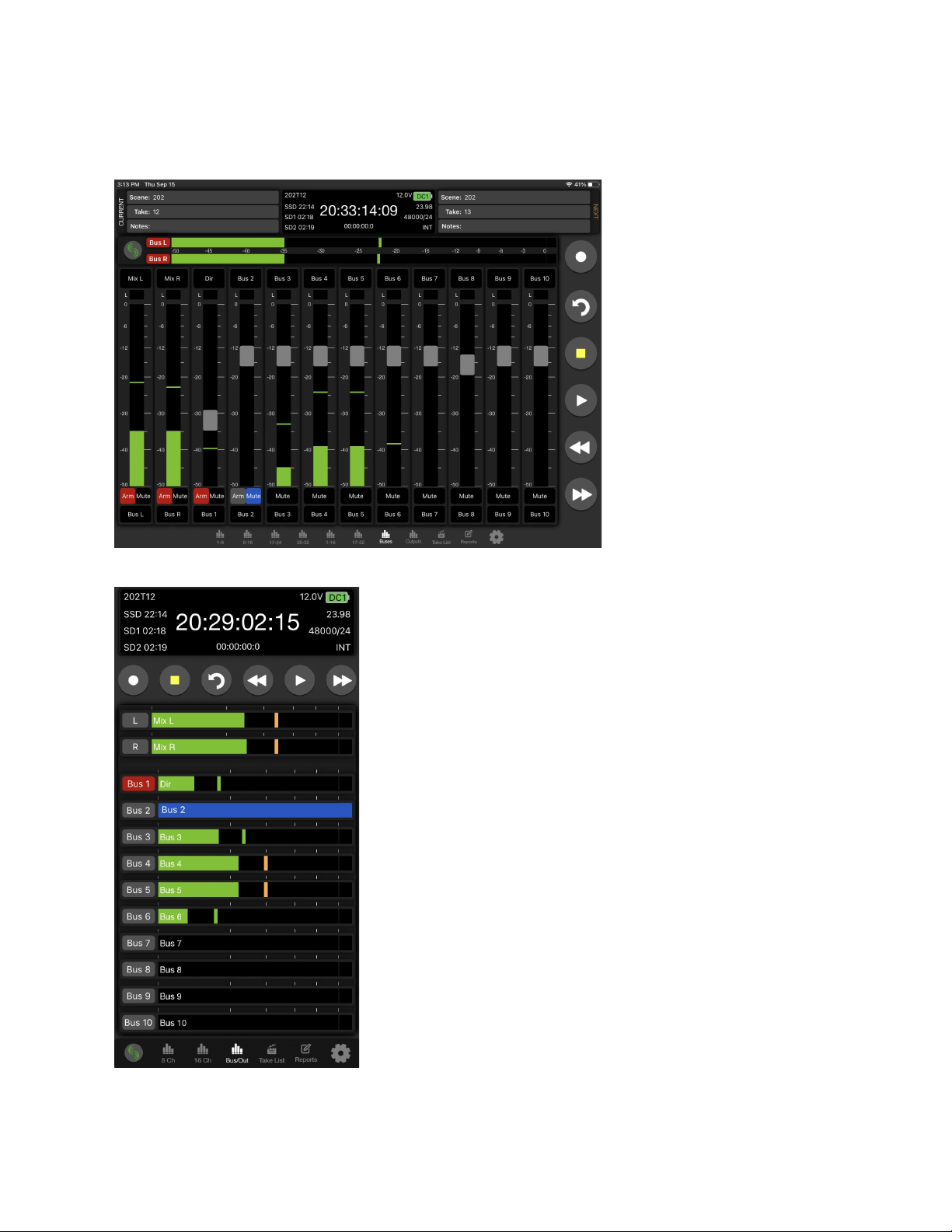
Bus Meters View
The Bus Meters view is similar to the Channel Meters view except that it displays metering and control for buses.
To access on a tablet, tap the Buses Tab. To access on a phone, tap the Bus/Out Tab
Scorpio User Guide 109
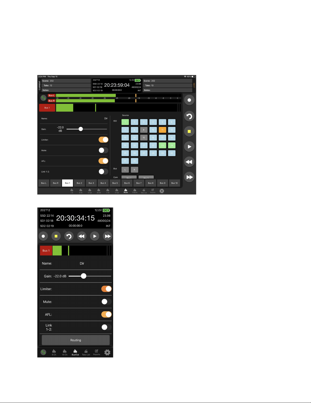
Fat Bus Screen
A buses detailed settings (Name, Gain, Limiter, Mute, AFL, Linking, and Routing) can be configured from its Fat Bus screen which is
accessed from the Bus Meters view as follows:
1. For a tablet, tap its Fat Bus Screen Access touch zone at the bottom of each Bus strip.
2. For a phone, tap its Bus meter.
Scorpio User Guide 110
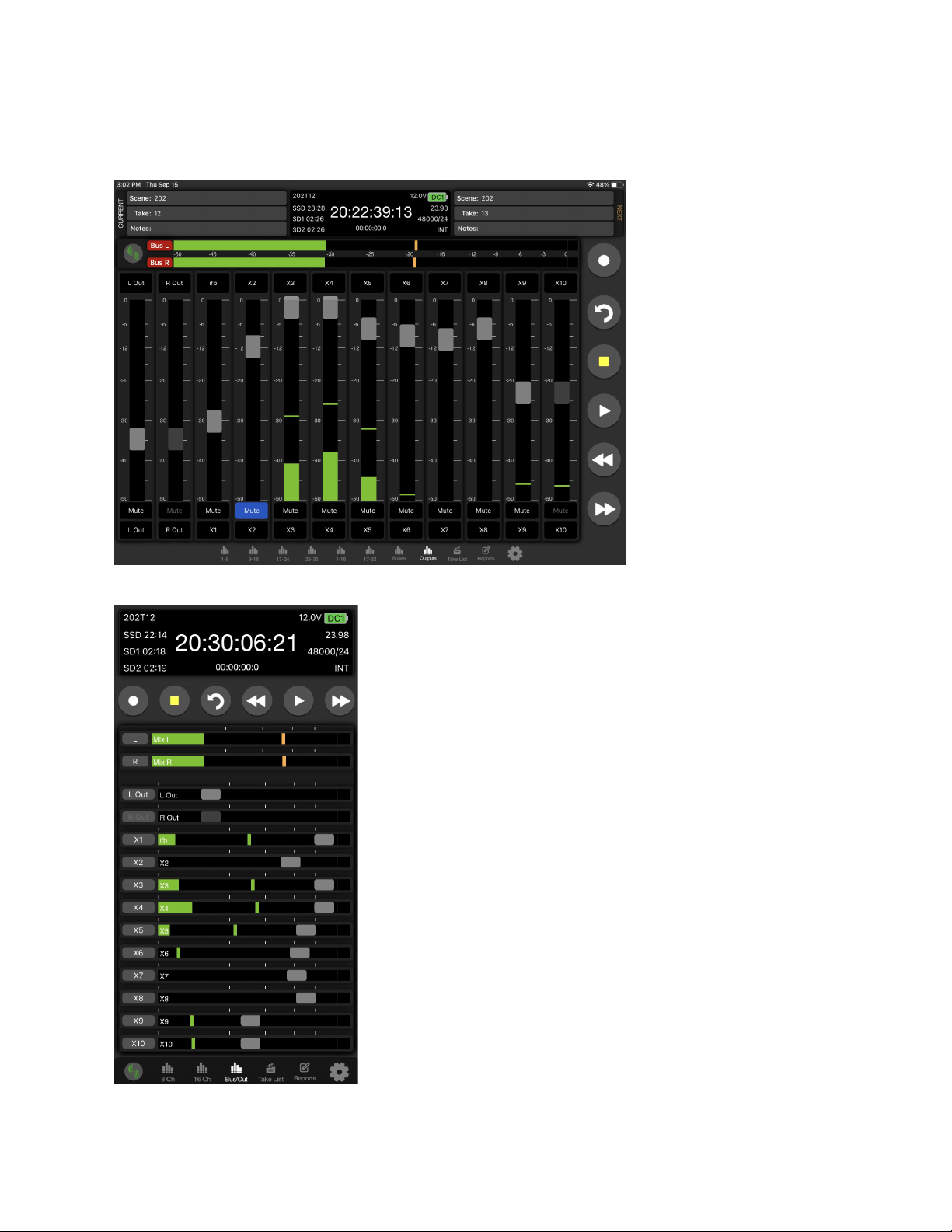
Output Meters View
The Output Meters view is similar to the Channel and Bus Meters view except that it displays metering and control for outputs.
To access on a tablet, tap the Outputs Tab. To access on a phone, tap the Bus/Out Tab and swipe up.
Scorpio User Guide 111
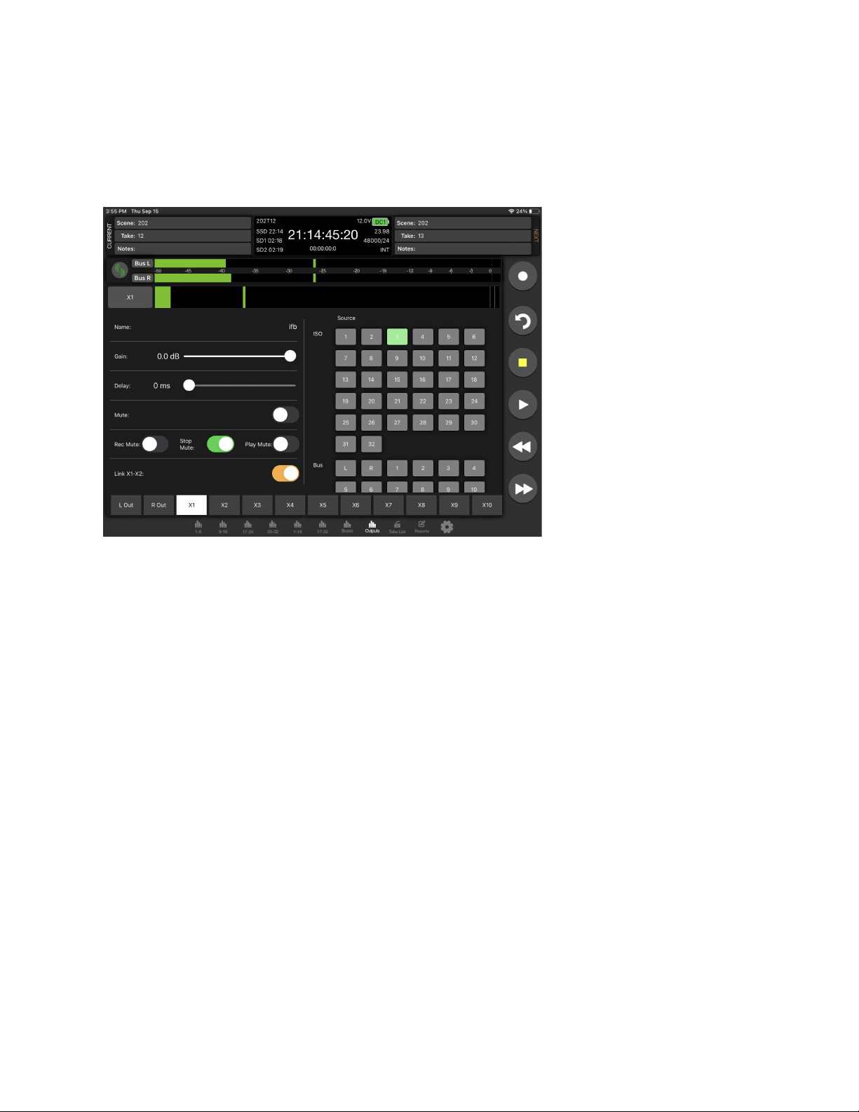
Fat Output Screen
An output’s detailed settings (Name, Gain, Delay, Mute, Linking, Rec/Stop/Play Auto-mute, and Routing) can be configured from its
Fat Output screen screen which is accessed from the Outputs (tablet) or Bus/Out (phone) Meters view as follows:
1. For a tablet, tap its Fat Out Screen Access touch zone at the bottom of each Output strip.
2. For a phone, tap its Output meter. First swipe up in the Bus/Out tab to display the Output meters.
Take List
From the Take List, enter metadata for Next, Current, or previous takes, select a take for playback, or view take information. The
Take List View on a Tablet displays the Take List, Take Edit, and Take Info windows simultaneously. The Take List on a phone
displays the Take List, selecting a take will enter the Take Edit view, selecting the ‘i’ icon will display the Take Info view.
In stop mode, touch a take’s play icon to play back that take.
Next Take Metadata
Edit scene, take, sticky notes, notes, and track names for the upcoming take.
Current and Previous Take Metadata
Edit scene, take, notes, track names, and circle the current or previously recorded take.
Take Info
Displays timecode, user bits, frame rate, duration, media, roll/folder, date, time, sample rate, bit depth, channels, and whether the
take is poly- or monophonic.
Scorpio User Guide 112
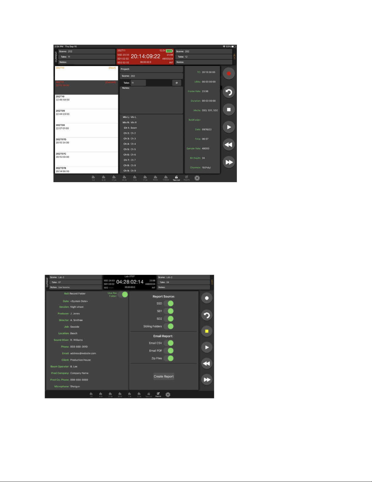
Sound Report
Create Report
1. Touch “Reports” icon on the bottom of the screen.
2. Select the source(s) from which the desired info resides. Sibling folders (folders at the same directory level) may be
included in the same report by selecting “Sibling Folders.”
3. Select which Sound Report format to send. Select Email CSV and/or Email PDF.
4. Select whether to send the CSV and PDF files individually or all as a single compressed .zip file.
5. Touch the Create Report button. Sound Reports will be shared via email while simultaneously being created on the
selected source drives.
To create a report from a different day’s folder than the currently active one, go to the 833’s Take List > Next Take > Rec Folder and
highlight the shoot day folder you want to create the report for, then press ‘Set Folder’.
‘[current]’ in orange text appears after the name of the current record folder.
Scorpio User Guide 113
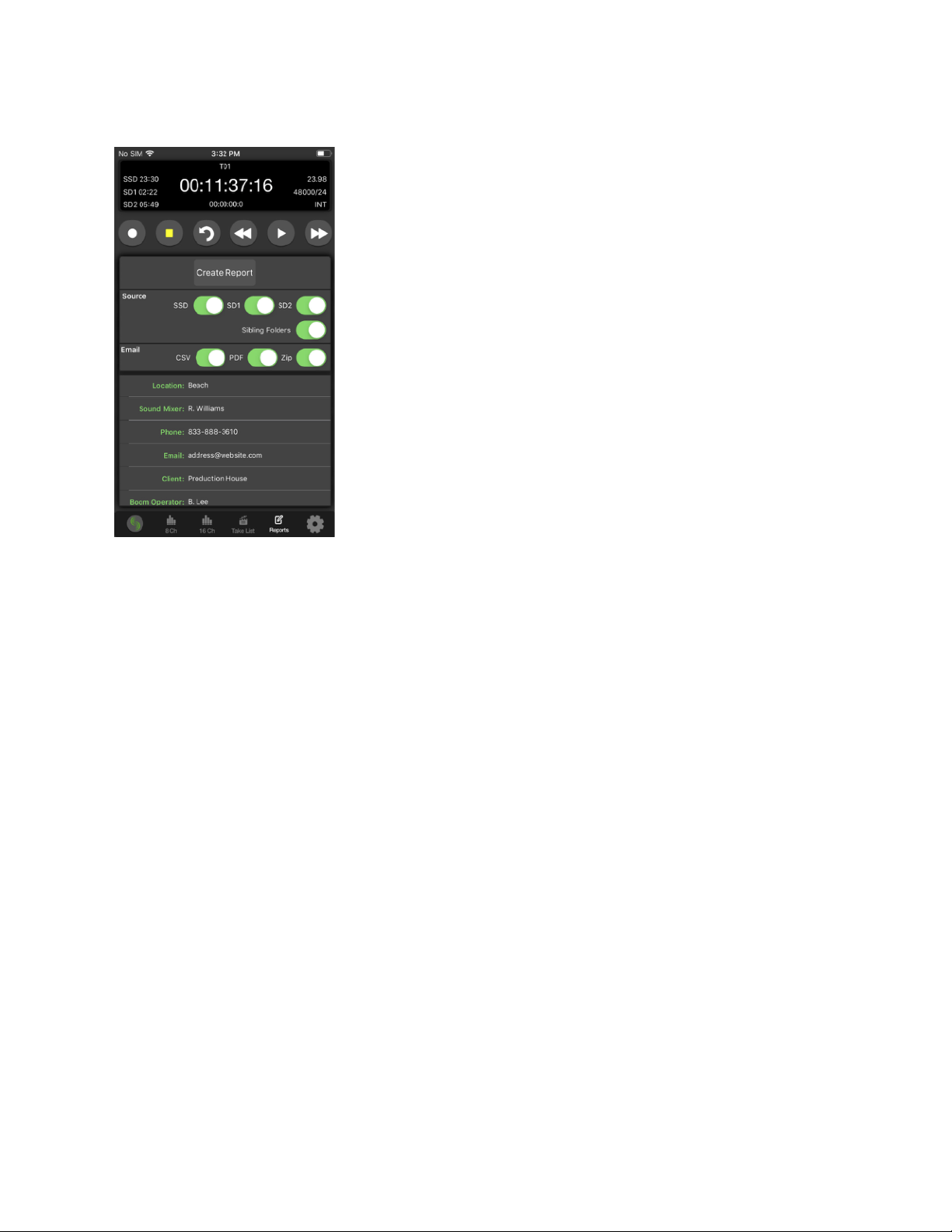
To merge several folders or days into one sound report in SD-Remote, activate ‘Sibling Folders’. This will print all contents of all
folders at the same directory level as the current record folder creating a sound report.
Settings
SD-Remote Version
Displays the version number.
Connect Via (Android Tablet)
Select whether to connect via USB or Bluetooth. If Bluetooth is selected, use the Connect Icon on the Meter views to connect to a
device.
Hide Faders
Turn On to hide faders in the Meter views. Faders are still available in the channel screen.
Hide Channel Trims (Tablet)
Turn On to hide faders in the Meter views. Faders are still available in the channel screen.
Hide Channel Mute (Tablet)
Turn On to hide faders in the Meter views. Faders are still available in the channel screen.
Auto AFL Bus
Determines whether a bus should automatically be solo’d when accessing its Fat Bus Screen. When set to Off, the bus will not
automatically be soloed.
Auto PFL Channel
Determines whether a channel should automatically be solo’d when accessing its Fat Channel Screen. When set to Off, the channel
will not automatically be soloed.
Meter View Transport Lock (Phone)
Enable to prevent accidental transport commands.
Meter View Arm Lock (Phone)
Enable to prevent accidental arming disarming in the Meter views. Track arming is still available in the channel screen.
File Transfer Mode
Touch to put the 8-Series into File Transfer Mode.
Scorpio User Guide 114
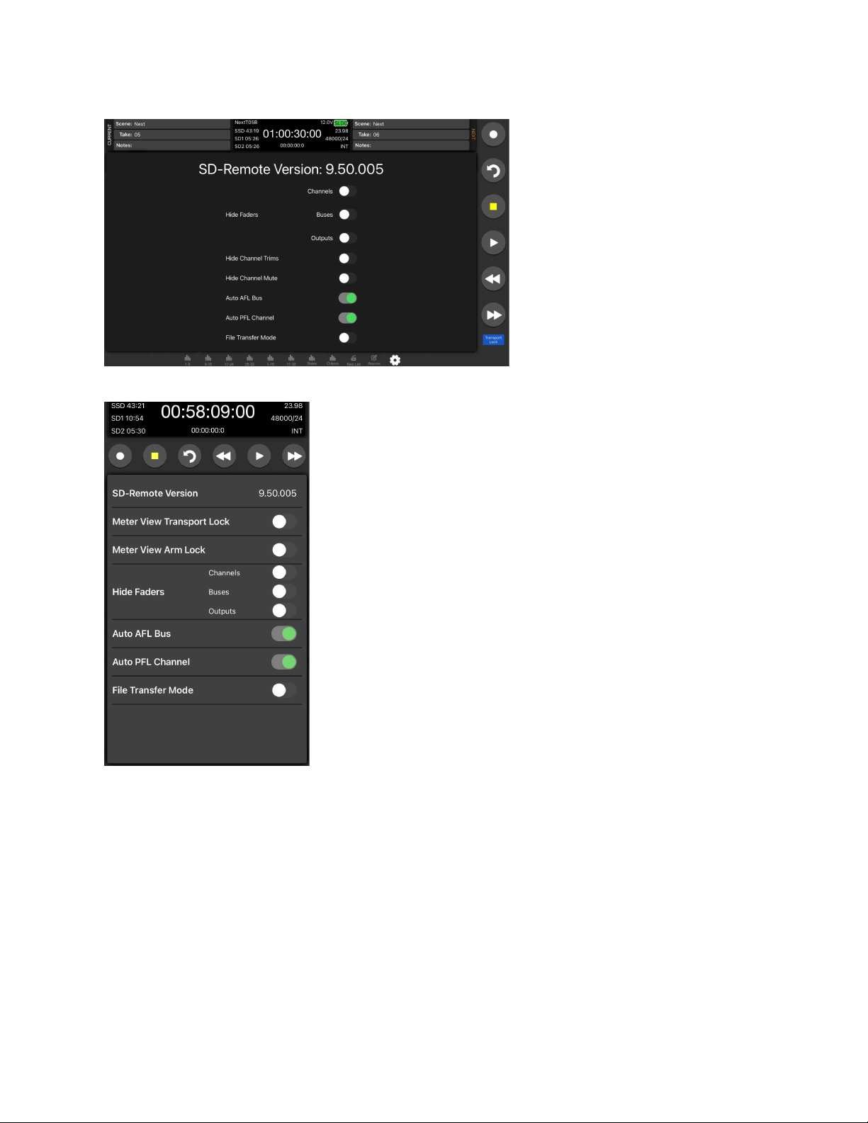
Scorpio User Guide 115
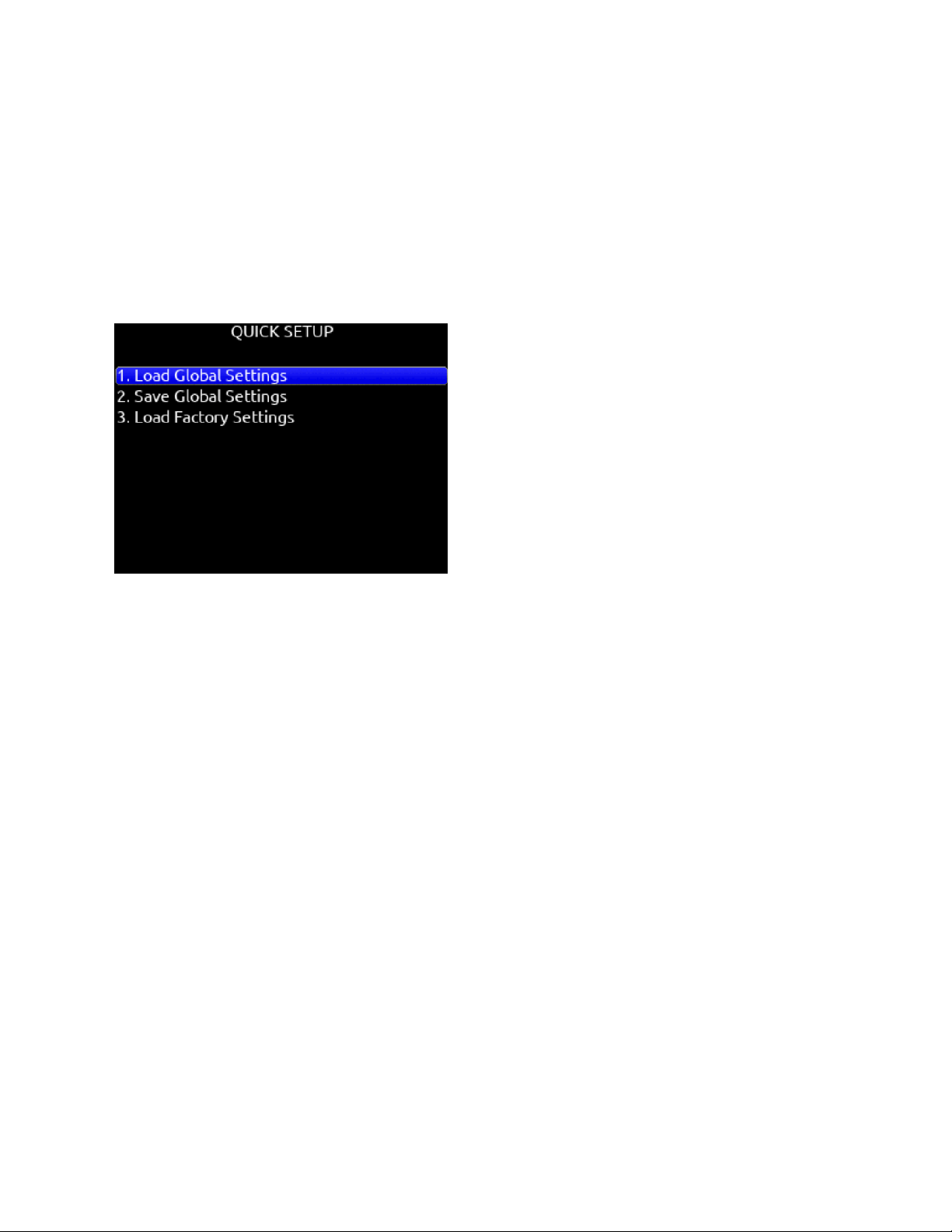
Quick Setup
Load Global Settings
Selects a saved settings file for loading. [User-saved Global settings]. Only settings files created using the Scorpio can be loaded,
not other 8-series models.
Save Global Settings
Saves Global settings to various destinations. [SSD Drive (internal), INT1-4 (internal), SD1 and SD2]
Load Factory Settings
Selects factory settings to be loaded for entire unit.
USB-A
USB-A allows multiple devices to be used to control and monitor various functions of the Scorpio. Should multiple devices be used
simultaneously, the use of a USB-A type hub is required.
USB-C
USB-C allows for high-speed file transfer between a computer and any of the Scorpio’s media.
Note: All other functionality is suspended in USB File Transfer mode.
2-In 2-Out USB audio is available via the USB-C port on the Scorpio. All routing is handled through the channel and output routing
matrices. No special drivers are needed as the built-in OS drivers will work properly.
Windows OS users - 96kHz max sample rate, MacOS users - 192kHz max sample rate.
USB Audio is supported for Windows 10 and above.
Scorpio User Guide 116

Dante
Scorpio is capable of connecting to a Dante network, simultaneously receiving and sending up to 32 channels of audio at sample
rates from 44.1kHz up to 96kHz and 16 channels of audio at 192 kHz. Scorpio channels 1-32 may be sourced from Dante receive
channels 1-32. Each Dante input may be selected as a source in the Channel Setup menu. Each Dante output may be sourced
from ISOs (pre- or post-fade), Buses and Outputs (post-delay). All network routing should be done through Audinate’s Dante
Controller application, found at www.audinate.com. Once the initial configuration has been performed, the Scorpio will keep its
Dante configuration through power cycles. It is recommended that, in most situations, Scorpio is selected as “Preferred Master”
under the “Clock Status” tab of Dante Controller. The Primary Dante connection is the RJ45 jack closest to the center of the unit.
Use the Primary connection first. A second Dante device may be connected to the Secondary (outermost) RJ45 jack.
Scorpio User Guide 117

Specifications
Specifications are subject to change without prior notice.
For the latest information available on all Sound Devices products, visit our website: www.sounddevices.com
Frequency Response
10 Hz to 80 kHz ± 0.5 dB (192 kHz sample rate, re 1 kHz)
THD + Noise
0.005% max (mic in, 1 kHz, 22 Hz–22 kHz BW, trim at 20, fader at 0, -10 dBu in)
Equivalent Input Noise
-131 dBV (-129 dBu) max (mic in, A-weighting, 76 dB gain, 150 ohm source impedance)
Processing Engine
Highly extensible, full FPGA-based audio processing, 3 FPGAs
Six-way ARM multiprocessor system
64-bit audio processing precision
Audio over Ethernet
Dante, AES67 compatible
32 channels in, 32 channels out (up to 96 kHz); 16 channels in, 16 channels out (192 kHz)
1 Gb/s Ethernet, 2 ports, transformer-balanced
Inputs
Mic/Line inputs: 16 total, all fully featured; 6 on full-size XLR, 2 on TA3, 8 on TA5
Mic-level inputs: (XLR, TA3, TA5): Class-A, discrete differential long-tail pair, 4k ohm input impedance
Line-level inputs: (XLR, TA3, TA5): active-balanced, 4k ohm input impedance
48V phantom: full 10mA to all 16 inputs simultaneously
22 Total analog inputs: 16 mic-line inputs, 6 on returns
AES3 or AES42 available on XLR inputs 1 and 6
AES42: +10 V, 250 mA available, mode-1, auto-ASRC
USB Audio: 2 inputs
A20-Nexus: 8 receiver inputs
SL-2 inputs: SuperSlot or UniSlot
SL-6 inputs: SuperSlot or UniSlot
Rtn A, B, C (3.5 mm/10-pin): unbalanced 2-channel, 4k ohm input impedance
Com Rtn 1,2 (TA3, 3.5mm) balanced, 1-channel, 8k ohm input impedance
External Slate Mic (TA5): balanced, 8k ohm input impedance, menu-selectable 12 V phantom
Buses
12 Buses (L, R, 1-10)
Left and Right Mix Bus receives post-fade isolated channels. Optional NoiseAssist plugin instances can be applied to any bus.
Buses 1-10 can receive pre-fade, post-fade, or independent send level from isolated channels, Returns A, B, or C, and Com Returns
1 and 2.
Maximum Input Level
Mic: +8 dBu (2.0 Vrms)
Line: +28 dBu (19.5 Vrms)
Rtn A, B, C: +18 dBu (6.2 Vrms)
Com Rtn 1, 2: +24 dBu (12.3 Vrms)
External Slate Mic: +12 dBu (3.2 Vrms)
High-Pass Filters
Adjustable 10 Hz to 320 Hz, 18 dB/oct. 1st stage analog (before preamp), 2nd stage digital.
Limiters
Limiters available at all channels, buses, headphones, for all sample rates
Analog first stage, all subsequent stages digital
Attack time: adjustable 1 to 200 ms
Release time: adjustable, 50 ms to 1000 ms
Threshold: adjustable, -2 dBFS to -12 dBFS
Scorpio User Guide 118

Selectable ratio: inf:1, 20:1, 18:1, 16:1, 14:1, 12:1, 10:1
Knee: soft, hard
Compressors
Compressors available at all channels (pre- or post-fade) and buses for all sample rates
Attack time: adjustable, 1 to 200 ms
Release time: adjustable, 50 ms to 1000 ms
Threshold: adjustable, 0 dBFS to -40 dBFS
Selectable ratio: adjustable, 1:1 to 20:1
Knee: soft, hard
Delay
Channel Adjustable 0-50 ms
Output Adjustable 0-500 ms
Maximum Gain
Trim stage (mic input): 76 dB
Trim stage (line input): 50 dB
Fader stage: 16 dB
Bus stage: 16 dB
Headphone stage: 20 dB
Mic-to-Line: 108 dB
Mic-to-Headphone: 112 dB
TA5 (along with mic input pins) for single connection to headset + mic
High output, 4 ohm output impedance, 400 mW + 400 mW at each connector, all individually driven
Compatible with headphones of any impedance
Outputs
XLR (L, R) active-balanced, 250/3.2k/120 ohms (mic/-10/line)
Hirose 10-pin (L, R) active-balanced, 250/3.2k/120 ohms (mic/-10/line)
TA3 (X1-X6) active-balanced, 250/3.2k/120 ohms (mic/-10/line)
3.5mm (X7, X8): unbalanced, stereo, 1.8k ohms
Headphone Outputs
¼”, 3.5 mm
TA5 (along with mic input pins) for single connection to headset + mic
High output, 4 ohm output impedance, 400 mW + 400 mW at each connector, all individually driven
Compatible with headphones of any impedance
Maximum Output Level
(all into 10k load)
Line: +20 dBu (7.8 Vrms)
“-10”: +6 dBu (1.5 Vrms)
Mic: -20 dBu (0.078 Vrms)
X7/X8 Out: +6 dBu (1.5 Vrms)
Headphone outputs (¼”, TA5, X9/X10): +14 dBu (4.0 Vrms)
A/D converters
32-bit, 120 dB, A-weighted dynamic range typical
Sampling rates 44.1 kHz, 47.952 kHz, 48 kHz, 48.048 kHz, 96 kHz, 192 kHz
Digital Outputs
AES3 transformer-balanced, in pairs; 1-2 (XLR-L), 3-4 (XLR-R), 5-8 (Hirose 10-pin A)
110 ohm, 2 V p-p, AES and S/PDIF compatible
Recording
Internal 256 GB SSD, two removable SD Cards
10% over-provisioned for optimum performance
Selectable bit depth 16 or 24-bit
Simultaneous recording to internal SSD and the two SD cards
exFAT formatting
Scorpio User Guide 119

36 tracks (32 ISO channels, 4 buses)
Broadcast WAV monophonic and polyphonic file format
64-bit WAV (RF64) monophonic and polyphonic; support for files > 4 GB
AAC 2 track at 48 kHz, selectable bit rate 32, 64, 128, 192, 256 kbps
Automatic Mixing
Dugan Automixer up to 16-channels on Left and Right Mix bus
MixAssist up to 16-channels on Left and Right bus
Noise Suppression
Via optional paid Sound Devices NoiseAssist or CEDAR sdnx Plugins
Two, four, or eight instances of Noise Suppression can run on any combination of isolated channels (excluding 17-32 on Scorpio), or
buses.
Attenuation range: 0-20 dB
NoiseAssist operates with sampling rates of 44.1 kHz to 48.048 kHz.
CEDAR sdnx operates with sampling rates of 44.1 kHz to 96 kHz.
NoiseAssist audio path latency: 0.77 ms @ 48kHz
CEDAR sdnx audio path latency: 0.27 ms @ 48kHz, 0.14ms @ 96kHz
USB
USB-C (USB 3.1 type 1) for file transfer of internal SSD, both SD Cards
USB-C 2-in/2 out audio streaming
USB-A host for keyboard, external controller, external USB hubs supported for connecting multiple devices
Timecode and Sync
Modes Supported: Off, Rec Run, Free Run, 24h Run, External, including External Auto-Record and Continuous modes.
Frame Rates: 23.98*, 24, 25, 29.97 DF, 29.97 ND, 30 DF, 30 ND
Sample/Timecode Accuracy: 0.1 ppm (0.25 frames per 24 hours)
Timecode Input: 20k ohm impedance, 0.3 V - 3.0 V p-p (–17 dBu - +3 dBu)
Timecode Output: 75 ohm impedance, 5 V p-p (+7 dBu)
Word Clock Input: 10k/75 ohm selectable impedance, 1-5 V p-p input sensitivity
Word Clock Output: 75 ohm impedance, 5 V p-p output, at SR
Remote Control
Sound Devices CL-16 Linear Fader Controller
Sound Devices CL-12 Linear Fader Controller
USB MIDI MCU Control - supported 3rd party fader controllers
SD-Remote Android Tablet app via USB or Bluetooth LE
SD-Remote Android Phone app via Bluetooth LE
SD-Remote iPad and iPhone app via Bluetooth LE
USB Keyboard
External Timecode Record Trigger
File Delivery to Cloud
Compatible with Frame.io Camera to Cloud
Compatible with Viviana Cloud
LCD
320x240, transflective, excellent sunlight visibility
Larger touchscreen display available via SD-Remote app
Power
External: 10-18 V input on locking TA4 connector, pin-4 = (+), pin-1 = (-),
Dual rear-mount Sony-style L-mount batteries with chargers
Current Draw, at 12V no battery charging:
All mic preamps off: 950 mA
All mic preamps on: 1.26 A
All mic preamps on, 192 kHz sample rate, recording to internal SSD and 2 SD Cards: 1.42 A
All mic preamps on, 192 kHz sample rate, recording to internal SSD and 2 SD Cards, Dante enabled: 1.67 A
Intelligent power-down of unused mic preamps and other internal circuits
Smart Battery telemetry supported via DC Input
Scorpio User Guide 120

Environmental
Operating: -20° C to 60° C, 0 to 90% relative humidity (non-condensing)
Storage: -40° C to 85° C
Dimensions (H x W x D)
5.1 cm x 32 cm x 20.5 cm
2.0 in. x 12.6 in. x 8.1 in
Weight
5.8 lbs (unpackaged, without batteries)
2.63 kg (unpackaged, without batteries)
Scorpio User Guide 121

Legal Notices
This product incorporates software subject to the BSD license:
Copyright 2001-2010 Georges Menie (www.menie.org)
All rights reserved. Redistribution and use in source and binary forms, with or without modification, are permitted provided that the
following conditions are met
* Redistributions of source code must retain the above copyright notice, this list of conditions and the following disclaimer.
* Redistributions in binary form must reproduce the above copyright notice, this list of conditions and the following disclaimer in the
documentation and/or other materials provided with the distribution.
* Neither the name of the University of California, Berkeley nor the names of its contributors may be used to endorse or promote
products derived from this software without specific prior written permission.
* THIS SOFTWARE IS PROVIDED BY THE REGENTS AND CONTRIBUTORS ``AS IS’’ AND ANY EXPRESS OR IMPLIED
WARRANTIES, INCLUDING, BUT NOT LIMITED TO, THE IMPLIED WARRANTIES OF MERCHANTABILITY AND FITNESS FOR
A PARTICULAR PURPOSE ARE DISCLAIMED. IN NO EVENT SHALL THE REGENTS AND CONTRIBUTORS BE LIABLE FOR
ANY DIRECT, INDIRECT, INCIDENTAL, SPECIAL, EXEMPLARY, OR CONSEQUENTIAL DAMAGES (INCLUDING, BUT NOT
LIMITED TO, PROCUREMENT OF SUBSTITUTE GOODS OR SERVICES; LOSS OF USE, DATA, OR PROFITS; OR BUSINESS
INTERRUPTION) HOWEVER CAUSED AND ON ANY THEORY OF LIABILITY, WHETHER IN CONTRACT, STRICT LIABILITY,
OR TORT (INCLUDING NEGLIGENCE OR OTHERWISE) ARISING IN ANY WAY OUT OF THE USE OF THIS SOFTWARE, EVEN
IF ADVISED OF THE POSSIBILITY OF SUCH DAMAGE.
FCC & ISED Compliance Statements
This device complies with part 15 of the FCC Rules. Operation is subject to the following two conditions:
(1) This device may not cause harmful interference, and (2) this device must accept any interference received, including interference
that may cause undesired operation.
Changes or modifications not expressly approved by the manufacturer could void the user’s authority to operate the equipment.
This device contains transmitter module FCC ID: XF6-M7DB6
This device contains transmitter module IC: 8407A-M7DB6
FCC Interference Statement
Scorpio User Guide 122

This equipment has been tested and found to comply with the limits for a Class B digital device, pursuant to part 15 of the FCC
Rules. These limits are designed to provide reasonable protection against harmful interference in a residential installation. This
equipment generates, uses and can radiate radio frequency energy and, if not installed and used in accordance with the
instructions, may cause harmful interference to radio communications. However, there is no guarantee that interference will not
occur in a particular installation.
If this equipment does cause harmful interference to radio or television reception, which can be determined by turning the equipment
off and on, the user is encouraged to try to correct the interference by one or more of the following measures:
—Reorient or relocate the receiving antenna.
—Increase the separation between the equipment and receiver.
—Connect the equipment into an outlet on a circuit different from that to which the receiver is connected.
—Consult the dealer or an experienced radio/TV technician for help.
FCC & ISED User Statement
This device complies with FCC and ISED RF exposure limits for general population / uncontrolled environments.
Cet appareil est conforme à la norme FCC et ISED les limites d’exposition pour la population générale / l’exposition incontrôlée.
A separation distance of at least 20cm must be maintained between the antenna and all persons. This device must not be
co-located with any other antenna or transmitter.
This device (containing FCC ID: XF6-M7DB6, IC: 8407A-M7DB6) has been approved to operate with the antenna type listed below:
Model: GW.71.5153 Type: 2.4/5.8GHz Dipole Antenna
Manufacturer: Taoglas Max. Gain: 3.8dBi (2.4GHz), 5.5dBi (5.8GHz)
No change to the antenna type is permitted. Any change to the antenna could result in the device exceeding the RF exposure
requirements and void the user’s authority to operate the device.
This Device complies with Industry Canada License-exempt RSS standard(s). Operation is subject to the following two conditions: 1)
this device may not cause interference, and 2) this device must accept any interference, including interference that may cause
undesired operation of the device.
Cet appareil est conforme avec Industrie Canada, exempts de licence standard RSS (s). Son fonctionne-
ment est soumis aux deux conditions suivantes: 1) ce dispositif ne peut pas causer d’interférences, et 2)
ce dispositif doit accepter toute interférence, y compris les interférences qui peuvent causer un mauvais
fonctionnement de l’appareil.
Incorrect use of batteries poses a danger of explosion. Replace only with the same or equivalent type.
Properly recycle batteries. Do not crush, disassemble, incinerate, dispose in a fire or expose batteries to high temperatures.
Scorpio User Guide 123
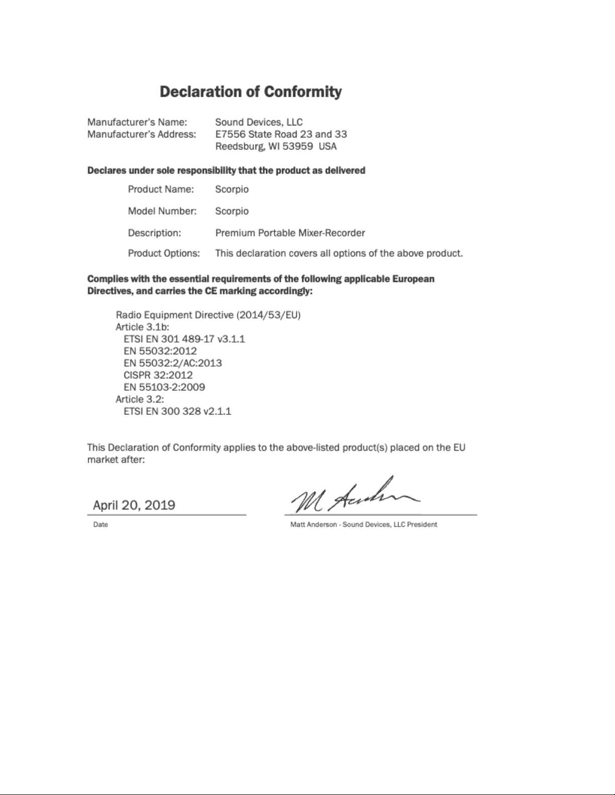
Scorpio User Guide 124

Warranty
Sound Devices, LLC warrants the items listed above against defects in materials and workmanship for a period of ONE (1) year
from date of original retail purchase. Users who register their product directly with Sound Devices Technical Support using the online
form or by phone, will receive an additional ONE (1) year of warranty coverage, extending the complete warranty period to TWO (2)
years from the date of original retail purchase. In order to extend the warranty coverage period, registration must be completed
within the initial ONE (1) year warranty period. Products must be purchased through authorized Sound Devices resellers to qualify
for Warranty coverage. Damage resulting from the opening of a Sound Devices product or attempted repairs by a non-authorized
Sound Devices repair technician will void warranty coverage.
This is a non-transferable warranty that extends only to the original purchaser. Sound Devices, LLC will repair or replace the product
at its discretion at no charge. Warranty claims due to severe service conditions will be addressed on an individual basis.
THE WARRANTY AND REMEDIES SET FORTH ABOVE ARE EXCLUSIVE. SOUND DEVICES, LLC DISCLAIMS ALL OTHER
WARRANTIES, EXPRESS OR IMPLIED, INCLUDING WARRANTIES OF MERCHANTABILITY AND FITNESS FOR A
PARTICULAR PURPOSE. SOUND DEVICES, LLC IS NOT RESPONSIBLE FOR SPECIAL, INCIDENTAL, OR CONSEQUENTIAL
DAMAGES ARISING FROM ANY BREACH OF WARRANTY OR UNDER ANY OTHER LEGAL THEORY. Because some
jurisdictions do not permit the exclusion or limitations set forth above, they may not apply in all cases.
For all service, including warranty repair, please contact Sound Devices for an RMA (return merchandise authorization) before
sending your unit in for repair. Product returned without an RMA number may experience delays in repair. When sending a unit for
repair, please do not include accessories, including SSD drives, CF cards, batteries, power supplies, carry cases, cables, or
adapters unless instructed by Sound Devices. Sound Devices repairs and replacements may be completed using refurbished,
returned or used parts that have been factory certified as functionally equivalent to new parts.
Sound Devices, LLC
Services Repair RMA #XXXXX
E7556 State Road 23 and 33
Reedsburg, WI 53959 USA
Telephone: +1-608-524-0625
Scorpio User Guide 125

Glossary
¼-inch jack
Common analog audio connector used as both an audio input and output. When a ¼-inch jack is described as TRS (tip-ring-sleeve)
it can be wired as either a balanced connection or as a two-channel connection. ¼-inch headphone jacks are typically wired as TRS
stereo jacks.
3.5 mm jack
Common small-format audio connector. Often used for headphones and -10 dBV signals for portable audio devices.
Advanced Audio Coding (AAC)
An audio coding standard for lossy digital audio compression. Designed to be the successor of the MP3 format, AAC generally
achieves better sound quality than MP3 at the same bit rate.
AES3
A standard for the exchange of digital audio signals between professional audio devices. An AES3 signal can carry two channels of
PCM audio over balanced, 110 ohm interconnections. AES3 is most commonly interconnected with XLR-3 cables.
AES42
A digital interface protocol for microphones and microphone inputs. Microphones conforming to this standard directly output digital
audio through an XLR or XLD male connector, rather than producing an analog output. AES42 microphones require powering.
Attenuation
A reduction in the level of an audio signal. Attenuation can be applied to both analog and digital signals. A fader is used primarily to
attenuate signals, though a small amount of positive gain is often available on a fader.
bEXT chunk
Broadcast WAV extension data added to the audio data in a WAV file. The bEXT chunk includes timecode and user bit data. For
systems that do not recognize the bEXT chunk this additional information is ignore
Bit depth
When converting between analog and PCM digital audio the amplitude of an analog signal is measured in finite steps, measured in
bits. Higher bit rates result in greater resolution of amplitudes, resulting in higher dynamic range. 24-bit audio, with a theoretical
maximum dynamic range of 144 dB, is the standard bit depth used throughout the audio chain for production.
Broadcast WAV, BWAV
Broadcast WAV files are WAV files with additional, non-audio data, such as bEXT chunk data. Broadcast WAV files offer timecode
support.
Bus
An audio path that is the destination of one or multiple (mixed) channels. A bus is typically routed to an output, a record track, or
both.
Camera return
An audio input on a mixer designed to receive the output, typically the headphone output, of a camera. Camera return inputs allow
the user to monitor the level and quality of the signal received at the camera. On the 833 the Aux In can be used as a source for
any channel.
CEDAR sdnx™
CEDAR Audio Ltd.’s highly-regarded noise suppression technology is available as an optional paid plugin from
store.sounddevices.com. Use CEDAR sdnx to reduce unwanted background noises so you can better capture dialog. CEDAR sdnx
has near-zero latency and one simple control for adjusting the amount of suppression. Up to 8 instances of CEDAR sdnx are
available per mixer-recorder/device. These instances can run on any combination of isolated channels (excluding 17-32 on Scorpio)
or bus.
Channel
A “slot” of a mixer that is controllable and routable. A given input feeds the channel and the channel’s settings process and route the
audio as required. It can also be thought of as the path its selected input signal takes on its way to its record track, a bus, or an
output.
Scorpio User Guide 126

Channel grouping
With the 833 all of the 8 channels can be grouped together so that their faders, record arming state mute states can be controlled
together. Channel grouping can be used as an alternative to sending channels to a bus.
Circled take
An identifying character, the @ symbol, which is placed in the file name to highlight a take. Circled takes can either be used to
identify good takes or to identify tracks or takes that will be ignored
Com return
A dedicated audio input designed to receive signals from a PL, or private line communications circuit. The com return on the 833
can routed to an output or a bus.
Com send
A dedicated output designed to send signal to a PL (private line, talkback) communications circuit. The com send is toggled by a
front panel switch.
dBFS
A measurement of the signal level of a digital signal in dB increments, dB relative to full scale signal. The maximum signal in dBFS
is 0 dBFS, with signals expressed with a negative sign. dBFS signal strength is an internal measurement and does not correspond
to analog signals unless the relationship between analog signal and digital signal is known.
Delay (channel)
Time delay that can be applied to an individual channel. Channel delay, typically set in milliseconds, is often used to compensate for
different acoustical or electrical arrival times of signals between channels.
Dugan Automix
An automatic mixing algorithm invented by Dan Dugan which when used across multiple microphone inputs for speech, makes
decisions about which inputs should be given priority due to speech being present vs. open, but unused inputs. This allows for
greatly improved audio by turning down the inputs that aren’t used and automatically turning up the inputs that are being used in
real-time and transparently
exFAT
A storage volume format that can be read and written from current versions of MacOS and Windows. exFAT supports volume sizes
up to 128 PB (gigantic), and individual files can have a maximum size of 16 EB (even more gigantic, bigger than the maximum
volume size).
Fader
A physical control on a mixing console, either a rotary or sliding potentiometer, that controls the level of a channel to a bus. Most
faders have more attenuation than gain available and a unity gain position where the input trim level established the level to the bus.
False take
A recorded take that was either erroneously recorded, or a take that needs to be repeated. It can be labeled after recording. An
identified false take is moved to the trash bin and the auto-incrementing take number is reset to the value prior to the false take.
ile list
Every file recorded by a recorder is visible in the file list. It can be viewed either on a recorder or from a computer when the
recording volume is mounted. The file list shows all the individual files recorded by a recorder.
Frame rate
The rate at which video or motion picture images are recorded or played back, measured in frames-per second (FPS). All audio and
video devices must be running at the same frame rate to keep audio and video synchronized. Timecode frame rates are either an
integer or non-integer value. Integer values include 24, 25, and 30 FPS. Non-integer frame rates include 23.976 and 29.97, and
29.97 drop FPS.
Frequency
The period at which a wave oscillates, measured in hertz (Hz). Frequencies audible to humans range from 20 Hz for very low
frequency signals to 20 kHz for very high frequency signals.
Gain
An increase (or decrease with negative gain) in the level of an audio signal. Gain can be applied in several locations, to both analog
and digital signals. In a field mixer the microphone preamplifier provides a substantial amount of gain at the trim to raise the low
Scorpio User Guide 127

level microphone signal to a usable signal in the mixer. Gain is also available at the fader. Gain of digital signals or line level analog
signals is often limited. Unity gain is gain stage that neither adds or subtracts level from a signal.
Headphone monitor
Often a separate bus with a dedicated headphone volume control, the headphone monitor typically is normalled to the main left/right
output bus of a mixer. Headphone sources can often be selected among soloed tracks or buses. In some products complex
headphone monitoring of MS Stereo, LR stereo, and ambisonic sources is available.
High pass filter (audio)
Also referred to as a low-cut filter, this circuit reduces the amount of low frequency content in an audio signal. A HPF is particularly
useful when recording speech since the human voice does not generate appreciable energy at low frequencies. The HPF reduces
non-speech signals such as environmental noise, wind noise, and microphone handling noise, improving the intelligibility of speech
and reducing low frequencies from overloading the input. The high pass filter is placed in the circuit close to the microphone
preamplifier.
High pass filters are often frequency selectable, ranging from 20 Hz to 200 Hz. HPF also have a slope, generally from 3 dB/octave
to 18 dB/octave. Greater/steeper slopes offer more attenuation of frequencies just below the set filter frequency.
Input
The physical connection and associated signal type from external sources connected to a device. Inputs can include microphone
inputs on XLR connectors or USB audio inputs from a computer. Depending on the architecture of the mixing console its inputs may
be hardwired to channels or channels can be selected from different inputs.
Input limiter
A limiter circuit reduces the peak signal levels of audio, generally to prevent signal overload. Analog inputs have a maximum input
signal level that can be reached before overload/distortion is introduced. Setting the input gain correctly so that input signals do not
reach this maximum level prevents most overload conditions. In the presence of very high, unexpected signals an input limiter
changes the gain of the incoming signal and prevents it from overloading. Input limiters are sometimes compressor-type circuits with
a ratio of infinity:1, meaning that any increase to the input signal into the limiter at the limiter threshold does not increase the output
signal of the limiter.
Several parameters may be available in a limiter, including knee, ratio, release, and threshold.
Isolated track
A recorded track of an individual microphone or sound source. “Iso” recordings allow for post-record mixing of individual sound
elements.
iXML
An extensible data schema for audio and related metadata stored in broadcast WAV files. Manufacturer-specific data generated
during recording is stored in iXML.
Line level
An analog audio signal used to interconnect audio equipment. Line level may be balanced or unbalanced, referenced to +4 dBu or
-10 dBV, professional or consumer respectively.
Low cut filter
See high pass filter.
Microphone level
The audio signal generated by a microphone. Mic level signals are very low level, requiring a microphone preamplifier to bring them
to usable, line levels. Interconnects with microphone level signals can be subject to noise and interference.
Mid-side linking (inputs)
When mid-side (MS) stereo inputs are used and the inputs are set to MS linking and MS decoder is activated for those inputs. This
yields a stereo signal with one fader controlling overall input level and control for the “width”, or amount of the side signal added.
With an MS matrix at the input, the signal is sent to an output bus as left/right stereo. Mixers with MS matrices often allow for
discrete mid and side signal recording. In that case the MS decoder can be activated at the headphone selection to monitor left/right
stereo.
MixAssist™
An exclusive Sound Devices automatic mixing algorithm which when used across multiple microphone inputs for speech, makes
decisions about which inputs should be given priority due to speech being present vs. open, but unused inputs. This allows for
Scorpio User Guide 128

greatly improved audio by turning down the inputs that aren’t used and automatically turning up the inputs that are being used in
real-time and transparently.
Mix track
A recorded track that is a sum of multiple tracks. In production sound the mix track is often a single summed track of all production
dialog elements. Mix tracks can also be sub-mixes of like microphones, such as a sub mix of just lavalier microphones or just boom
microphones.
Monophonic WAV
A WAV file that is comprised of a single track of audio. When recording multi-track audio with monophonic WAV files each track is
recorded to its own WAV file, with a file name indicating the track number. All associated monophonic files that are part of a
multi-track recording will be identical lengths.
Mute
A mute control is a convenient on/off switch for a channel and an easy way to remove a channel from appearing in downstream
buses. Mute an input or channel does not change levels or settings; when channels are muted and unmuted, their settings remain.
Notes (metadata)
A metadata field that is saved along with audio data in a recorded sound file, useful for sound report generation. Some workstation
software recognizes the notes field and presents it when viewing the sound file.
NoiseAssist™
An exclusive Sound Devices noise suppression algorithm which is available as an optional paid plugin from
store.sounddevices.com. Use NoiseAssist to suppress background noises such as traffic, generators, HVAC noise, and more. The
plugin continuously monitors background noise to give you clean audio for the entire take. Up to eight instances of NoiseAssist can
run on any combination of isolated channels (excluding 17-32 on Scorpio), bus L, or bus R.
NP-1(A) battery
A specific class of battery, originally developed by Sony. There are multiple chemistries in this class including lithium-ion and
nickel-cadmium.
Output
The physical connection and associated signal type sent from a device. Outputs can be source from inputs, buses, record tracks,
and other auxiliary signals.
Output auto-mute
When set, an output signal is muted when recording is stopped, restricting program audio from being sent to listeners “between
takes”.
Output delay
A digital delay applied at the output. Signal delay is often set at an output to compensate for the delay introduced by digital imaging
systems so that picture and sound remain in correct “lip sync”. Output delay is set in either frames or milliseconds.
Pan
When a channel is routed to a stereo-linked bus the level it appears at each bus is adjusted by a pan control. A channel with its pan
control “straight up the center”, or “centered” sends signal at the same level to each bus. A channel that is panned left or right sends
the signal to the left or right bus, respectively.
PFL, pre-fade listen
When an input or channel is selected for monitoring/solo with a PFL, the channel is routed to the headphone output before the
channel fader so that the fader position has no effect on the headphone level. Trim/gain changes to the input will change the
headphone output.
Phantom power
Condenser (capacitor) microphones require power for operation. They use power to charge the diaphragm backplate (for true
condensers) and power the impedance convert located adjacent to the microphone capsule. Phantom power is the method for
microphone inputs to supply DC power to the microphone through the same connection used for the audio signals from the
microphone.
Phantom power provides a positive voltage, typically between 11-52 VDC, with 48 V being the most common, on both pin-2 and
pin-3 with pin-1 used as ground. The DC voltage appears as a common-mode signal on the balanced connection and is rejected by
the connection’s differential amplifier. Phantom power has no effect on dynamic microphones.
Scorpio User Guide 129

Phase
The relationship one audio signal has in time with respect to another audio signal, defined in degrees of phase. When audio signals
are generated at identical times, they are “in phase” with each other. When one audio signal is time-delayed with respect to another
the signals are “out of phase”. Differing phase relationships can be introduced several ways, including when microphones are placed
at varying distances from a sound source, or electrical/digital delay is introduced to one signal with respect to another.
Phrase
A pre-set text string which can be used to quickly fill out the notes field.
Pre-fader routing
The signal from a channel is routed to a bus before the fader in the signal path. The input trim, if available, controls the channel level
sent to the bus. Isolated tracks are typically recorded pre-fader so that any level changes made to the faders don’t affect the
recorded signal.
Pre-roll
A continuous buffer that is always writing to memory offering a recording that begins prior to when the record button is activated.
Pre-roll is set in seconds, and the recording begins the set number of seconds prior to the button being pressed. This is helpful in
applications where an operator missed a cue to begin recording.
Polarity (audio)
The direction of the current flow of an audio signal is defined as polarity. The polarity of a signal can reversed when a balanced
audio signal connection has its pin-2 and pin-3 connections reversed. Single-ended signals can have their polarity reversed when
going through an “inverting” gain stage. It is best practice to have all incoming and outgoing signals with the same polarity
relationship.
Polyphonic WAV
An individual WAV file that contains multiple audio tracks. When recording multi-track audio with polyphonic WAV files all recorded
tracks are contained within a single WAV file.
Post-fader routing (after fade routing, AFL)
The signal from a channel is routed to a bus after the fader in the signal path. The fader controls the level of the channel at the bus.
Channels sent to a master bus, such as the left/right bus, are typically sent post-fader.
Post-roll
An extra period of time that is appended to the end of a recording when stop is pressed. If record is pressed during this period of
time, recording will resume within the same file with no audio lost. This is particularly useful should a Director call ‘cut’ prematurely
or accidentally.
Project
An option available for file organization on Sound Devices recorders. Projects are the highest level of file folder organization. The
project folder can contain sub-folders of scene files or recorded files directly.
Record bell
A tone generated in headphones to alert the listener that recording has started. The bell is also produced when recording has ended
with the stop button, when the recording volume is full, or when power is in a critical state.
Record Folder
The destination folder for recorded takes. The 8-Series supports a three-tier folder hierarchy allowing for flexibility in organizing
recordings.
Sampling rate
When converting between analog and PCM digital audio the analog signal is measured (sampled) in unique steps at a data rate
specified in kHz. Higher sampling rates allow for representing higher frequency analog audio. 48 kHz is the standard sampling rate
for production, worldwide. Higher sampling rates including 96 kHz and 192 kHz are used for high-precision applications where the
representation of audio above 20 kHz is required. A general rule is that the maximum analog audio frequency is ½ the sampling
rate.
Scene
On Sound Devices recorders the scene becomes part of the file name for a take. Scene names can be pre-loaded to quickly change
between scenes.
Scorpio User Guide 130

Slate microphone
A microphone, built-in or external microphone, on an audio mixer used to notate takes or communicate with sound team members
by the mixer’s user speaking into the microphone. Slate microphones are often routable to buses or tracks.
Smart Battery
A lithium-ion rechargeable battery with integrated telemetry indicating battery condition, run time and other useful data.
Stereo linking (inputs)
When active for stereo sources such as stereo microphones, linked inputs are hard panned to the left and right bus. Controls
including gain (trim), fader, high pass filter, delay, limiter, mute, and routing are controlled together.
Solo
A control on a mixer to route a channel to headphones while muting all others. Solo and PFL are related controls and in many
consoles are the same. Solo circuits can be exclusive—only one channel is sent to headphones at a time—or non-exclusive—any
number of channels can be sent to the solo circuit and appear in headphones.
SuperSlot™
SuperSlot™ is an electro-mechanical connection protocol, developed by Sound Devices, to simplify the interconnection of wireless
audio transmitters and receivers with audio mixers and cameras. SuperSlot provides, power, audio, and control signals over a single
multi-pin connection. SuperSlot-compatible products will be offered by multiple manufacturers, including wireless system
manufacturers, camera manufacturers, and audio mixer manufacturers.
TA-type connector (TA3, TA4,TA5)
Miniature XLR-type, locking connectors. TA3 connectors are used by Sound Devices for various inputs, outputs, and as balanced
and unbalanced connections. TA4 connectors are used by Sound Devices for DC power connections to the 833 mixer-recorder. TA4
is also used for audio connections from lavalier microphones to some wireless transmitters. TA5 connectors are used for the 833
headset input. TA6 connectors are presently not used by Sound Devices though they are used for audio connections by other
manufacturers.
Take
A recorded take is an individual recorded file (or files when recording monophonic WAV files) generated by a recorder. Take
numbers are auto-incrementing. Take numbers are added to the end of the file name.
Take list
Separate from a file list, a take list consolidates related files such as a group of monophonic WAV files generated by a single take
and presents them as a single take.
Test tone
See tone oscillator.
Timecode
A numerical clock value expressed in hours:minutes:seconds:frames, i.e. 04:59:39:05, used to synchronize cameras, video decks,
and audio recorders. Timecode requires clocks on devices to be synchronized, either through a wired or wireless connection
between devices, or through a process called “jam sync” where each device, which requires a high-precision clock, runs
independently after their clocks are synchronized.
Timecode mode
Sound Devices recorders offer multiple timecode modes. Different modes correspond to different timecode workflows. Common
modes available in Sound Devices recorders include:
record run - timecode advances only when recording is engaged
free run - timecode run continuously, typically with the start of production being at 0 hour
24 hour - similar to free run except the start time corresponds to time-of-day
ext TC - the recorder applies the value of an external timecode source.
Tone oscillator
A sound generator producing a sine wave tone at a given frequency at a given output level. With its known output level tone
oscillators are helpful to set gain structure between audio equipment.
Track
Scorpio User Guide 131

A single recorded audio signal. Common recorded tracks are the main left/right master audio bus and isolated (iso) channel
recordings. Iso tracks are typically identified by the channel of the same number, e.g. channel 1 is sent to track 1, channel 2 is sent
to track 2, etc.
Track arm
Tracks that are active and ready for recording are said to be “armed”. When recording begins all armed tracks begin recording.
Depending on the production is may be advantageous to arm and disarm tracks, especially to disarm unused tracks.
Track name
Individual tracks of a multi-track recording can be named to indicate microphone type or character name.
Trim
Also defined in mixers as “gain”, the trim adjustment is the first stage of gain of a microphone or line level input. Typical microphone
trim values range from 10 dB to 50 dB, depending on microphone sensitivity and volume of the sound source.
User bits
Static, numeric data that is available as part of a timecode signal. User bits are often used to indicate the date of a file. User bits are
four sets of two-digit hexadecimal numbers from 00 to ff.
WAV File
A universal, well-supported file type for sound file recordings. WAV files can contain one or more (up to 65,535) tracks of PCM audio
data at any sampling rate and bit depth. A standard WAV file is limited to a maximum file size of 4 GB. Sound Devices uses the
.WAV extension for recorded files, including for files with Broadcast WAV metadata.
WAV RF64
An extension of the WAV file type that supports file sizes larger than 4 GB. When recording high track count, high sampling rate
polyphonic WAV files, the 4 GB size limitation of WAV can be reached quickly. RF64 files larger than 4 GB require recording to a
volume type than can support file sizes larger than 4 GB.
Word clock
A reference signal used to synchronize the sampling rate of multiple digital devices.
XLR female
Industry-standard 3-pin locking audio connector for microphone and line-level sources. Predominantly used as an input. Also shown
as XLR-F.
XLR male
Industry-standard 3-pin locking audio connector for microphone and line-level sources. Predominantly used as an output. Also
shown as XLR-M.
Scorpio User Guide 132

Post Office Box 576
E7556 State Rd. 23 and 33
Reedsburg, Wisconsin 53959 USA
+1608.524.0625 main
800.505.0625 toll free (U.S. only)
www.sounddevices.com
Scorpio User Guide 133