Loading ...
Loading ...
Loading ...
page 8
OPERATION
Soft Rubber Gear Case Cover (Fig. 1)
The soft rubber gear case cover (J) is designed to eliminate metal gear case scuffs on painted or
polished surfaces.
The soft rubber gear case cover can be removed if required. To take off the cover, remove the
three mounting screws and lift the cover over the gear case.
WARNING: To reduce the risk of serious personal injury, turn tool off and disconnect
tool from power source before making any adjustments or removing/installing
attachments or accessories. Before reconnecting the tool, depress and release the
trigger switch to ensure that the tool is off.
FIG. 3A
M
N
O
E
I
I
Q
FIG. 3B
E
E
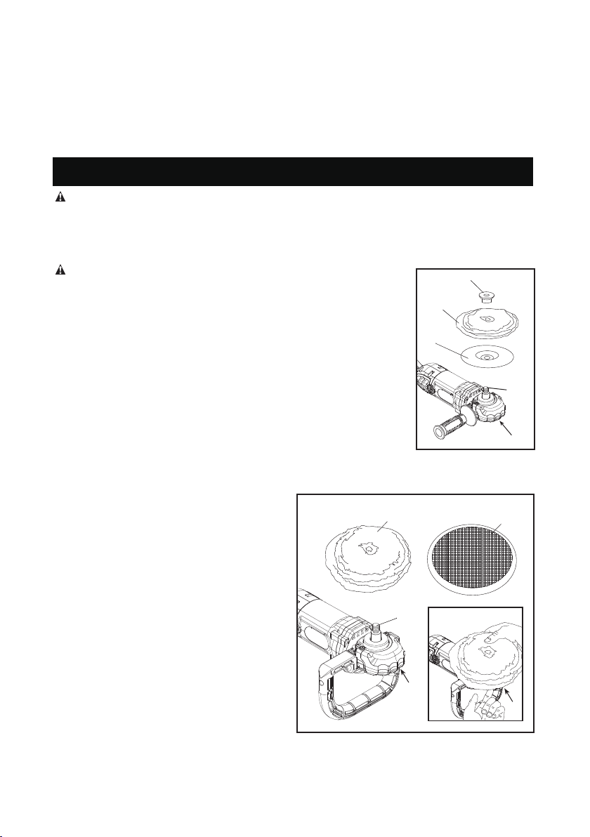
Attaching and Removing Polishing Pads (Fig. 3A&3B)
WARNING: To reduce the risk of serious personal injury, do not allow
1. Attach hook and loop foam or wool pad (P)
to hook and loop backing pad (Q), being
careful to center the backing pad (Q) with
the foam or wool pad.
2. Screw backing pad (Q) onto spindle (I),
while depressing spindle lock button (E).
any loose portion of the polishing bonnet or its attachment strings to spin
freely. Tuck away or trim any loose attachment strings. Loose and spinning
attachment strings can entangle your ngers or snag on the workpiece.
NOTE: This tool may use either type of polishing pad assembly described
below.
TO ATTACH POLISHING PAD WITH RUBBER BACKING PAD (FIG. 3A)
1. To attach polishing pad (N), push the hub of the clamp washer (M) through
the hole in the center of the polishing pad as far as it will go.
2. Engage the hexagonal hole in the backing pad (O). Holding the three pieces
rmly together, place the assembly on the tool spindle (I).
3. Depress the spindle lock button (E) while turning the pads clockwise to thread
them
completely on the spindle.
TO ATTACH POLISHING PAD WITH HOOK AND LOOP BACKING PAD (FIG. 3B)
TO REMOVE PADS
Depress the lock button (E) and turn the pad
by hand in the opposite direction until the pad
snaps into the lock position.
Once the pad is snapped into the lock position
ensure the pad is locked well by once again
turning the pad in the left and right direction
while still depressing the lock button (E).
If the pad is locked well it should not be possible
to turn the pad.
Then unscrew pads in normal direction for right
handed thread.
P
Loading ...
Loading ...
Loading ...