Loading ...
Loading ...
Loading ...
3. Mechanical Splice Kit with plastic insula-
tors (for 14, 12 and 10 Gauge AWG Wire,
or 2, 3 and 5.5mm
2
wire):
A. Cut off motor leads. Stagger lead and
wire length so that 2nd lead is 4"
(101.6mm) longer than 1st lead and 3rd
lead is 4" (101.6mm) longer than sec-
ond.
B. Cut off wire ends. Match colors and
lengths of power supply wires to colors
and lengths of motor leads.
C. Trim insulation back 1/2" (13mm) from
cable ends and motor lead ends.
D.Unscrew plastic caps from insulators.
Place a cap and a neoprene gasket
sleeve on each wire end to be spliced
(see Figure 8).
E. Slide insulator body onto one wire end
(Figure 8).
F. Insert wire end into butt connector and
crimp. Match cable and motor wire col-
ors (see Figure 9).
G.Center insulator body over splice and
slide neoprene sleeves into body as far
as they will go. Screw caps onto insula-
tor body (Figure 10) and tighten by hand
for a strong, waterproof splice.
POWER SUPPLY WIRE INSTALLATION
1. To test submersible, momentarily (no more
than 30 seconds) connect it to proper power
supply. Power supply frequency and voltage
must match motor nameplate frequency and
voltage to within ±10%.
2. Fasten power supply wires leads securely to
pump discharge section; leave 4-5" (100-
125mm) of slack in leads at this point.
Securely fasten leads to plastic pipe within 6"
(150mm) of the pump discharge section. Use
centering guides to protect wire and pipe
from rubbing the well casing.
3. Connect copper ground wire to motor brack-
et. Ground wire must be at least as large as
wires supplying current to motor. Consult
local codes for grounding information.
4. Use only submersible power supply wires
supplied by pump manufacturer. When low-
ering pump into well, secure supply wires to
discharge pipe at 10' (3.5M) intervals with
Scotch #33 electrical tape. DO NOT damage
pump wires.
NOTICE: To avoid dropping the pump down
the well or damaging cable or cable splices,
NEVER allow pump cable to support weight
of pump.
PUMP INSTALLATION
1. If a standard air over water pressure tank is
used, install two bleeder orifices about 2'
(.6M) apart as shown in Figure 13, Page 9.
Orifices will automatically charge the tank
with air. See Figure 13 to determine orifice
location.
NOTICE: If Pre-charged tank is used, DO
NOT install bleeder orifices. If pump and pre-
charged tank are replacing a standard tank
system, remove bleeder orifices before
installing pump in well.
2. To prevent losing pump down the well, con-
nect a safety rope strong enough to support
pump and drop pipe (minimum 5/16" (8mm)
twisted polypropylene or pronila rope) to eye-
let on pump discharge. Tie off other end of
safety rope securely to well seal, well cap or
pitless adapter.
3. Discharge outlet is 1
1
⁄4” NPT threaded.
Use 100 PSI rated polyethylene plastic pipe
for installations up to 100’ (30.5M) depth.
Use 160 PSI rated polyethylene plastic pipe
for installation up to 220’ (67.1M) depth.
For depths beyond 220’ (67.1M), use galva-
nized steel pipe for the entire drop pipe.
INITIAL START-UP/NEW WELLS
NOTICE: NEVER operate pump with discharge
valve completely closed. Pump can destroy itself
if run with discharge shut off (“deadheaded”) and
warranty will be void.
NOTICE: To avoid sand-locking pump, follow
procedure below when starting pump for the
first time. NEVER start a pump with discharge
completely open unless you have done this pro-
cedure first.
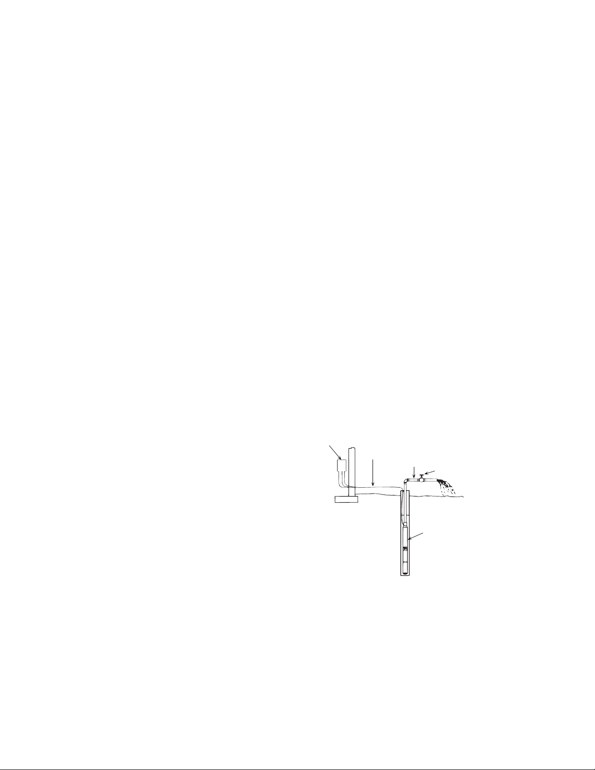
1. Connect a pipe elbow, a short length of pipe
and a gate valve to pump discharge at well
head (see Figure 11).
6
Control
center
or
electrical
disconnect
box
Temporary wiring
to control center or
electrical disconnect box
Temporary piping
Gate valve
Pump in well
Pump installation
for developing a well
689 0993
FIGURE 11 - Temporary connections while
cleaning well for start-up.
Loading ...
Loading ...
Loading ...