Loading ...
Loading ...
Motor is supplied with a copper ground wire.
Splice this ground wire to a copper conductor
that matches motor wire size specified in
Table III. See Page 5 for wire splicing
instructions.
Permanently ground pump, motor and control
box before connecting power cable to power
supply. Connect ground wire to approved
ground first and then connect to equipment
being installed.
Do not ground to a gas supply line.
Fire and electrical shock hazard.
If using a drop wire larger than No. 10
(5.5mm
2
) (for example, No. 8 (8.4mm
2
)
wire) between pump and control box, run
wire to a separate junction box. Connect
junction box to control box with a No. 10
(5.5mm
2
) or smaller wire (depending on amp
rating of pump – see Table III).
For more information, contact your local code
officials.
WIRING CONNECTIONS:
All wiring must meet National Electrical Code or
Canadian Electrical Code and local code
requirements.
Use only copper wire when making connections
to pump and control box.
To avoid over-heating wire and excessive voltage
drop at motor, be sure that wire size is at least
as large as size listed in Table III for your
horsepower pump and length of wire run.
NOTICE: When built-in overheating protection is
not provided, use with an approved overload
equipped motor control that matches motor
input in full load amps. Select or adjust over-
load element(s) in accordance with control
instructions. When built-in overheating pro-
tection is provided, use with an approved
motor control that matches motor input in full
load amperes.
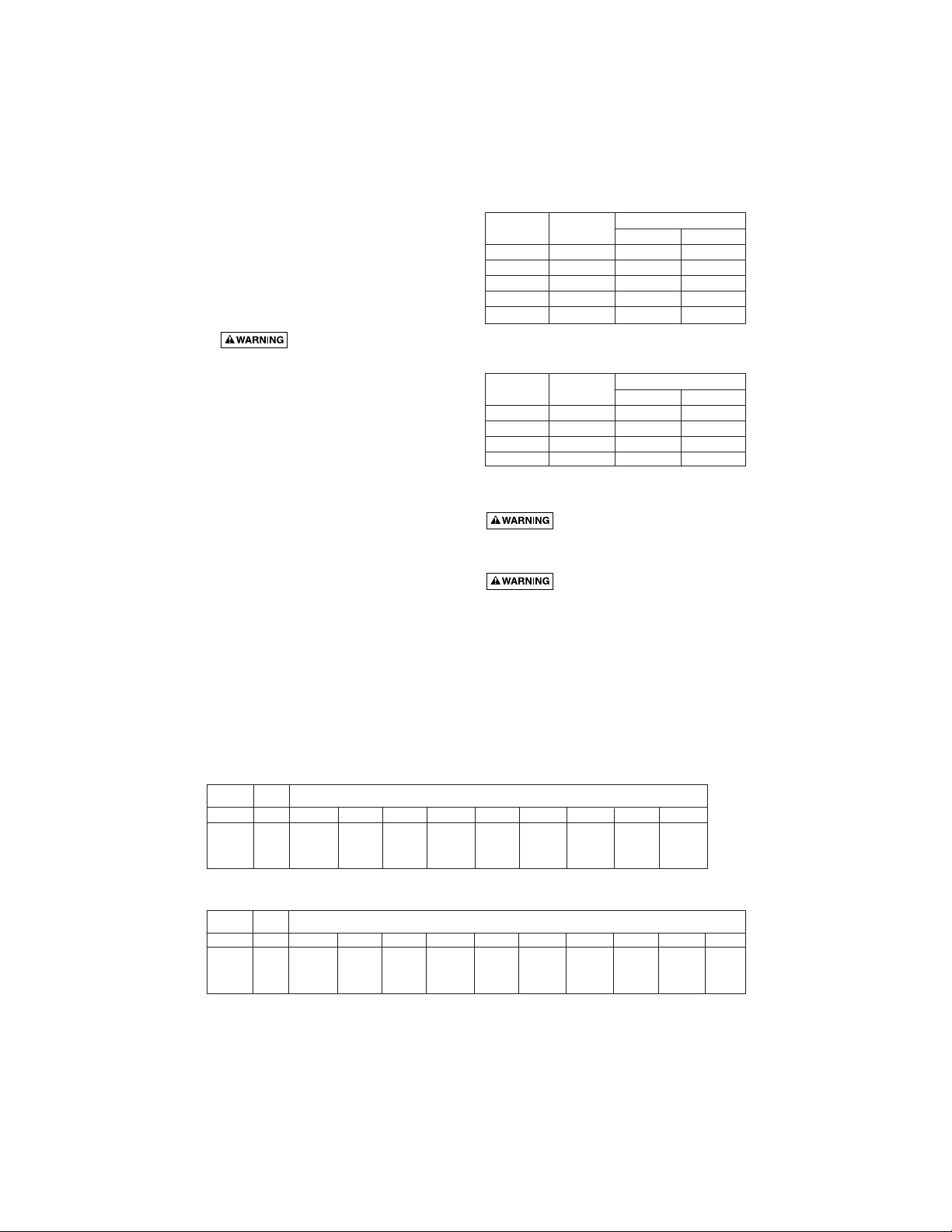
TABLE I: Recommended Fusing Data - 60 Hz.,
Single Phase, 3 Wire Submersible Pump Motors
TABLE II:
Recommended Fusing Data - 60 Hz.,
Single Phase 2 Wire Submersible Pump Motors
INSTALLATION WIRING DIAGRAMS -
SINGLE PHASE, 3 WIRE
For motors of 1
1
⁄2 HP and above, use
magnetic starter to avoid damage to pressure
switch. Consult factory for wiring information.
See Page 4 for 2 Wire Hookup.
Hazardous voltage. Can shock,
burn, or kill.
Ground control box, all metal plumbing, and motor
frame with copper wire in compliance with local
codes. Use a ground wire at least as large as the
wires supplying power to motor.
Permanently close all unused openings in this and
other equipment.
Disconnect power to control box before working on
or around control box, pipes, cable, pump, or
motor.
3
Fuse Size
HP Volts Stand Dual Elem.
1/2 115 35 20
1/2 230 20 10
3/4 230 25 15
1 230 30 20
1.5 230 35 20
Fuse Size
HP Volts Stand Dual Elem.
1/2 115 35 20
1/2 230 20 10
3/4 230 25 15
1 230 30 20
Volts HP KW 2.5 4 6 10 16 25 35 50 70
115V 1/2 .37 30m 49m 76m 119m 189m 292m 362m 445m 542m
1/2 .37 126 200 319 507 806 1282 1617 2038 2571
230V
3/4 .55 93 149 237 377 599 953 1202 1515 1911
1 .75 78 124 197 313 498 792 999 1260 1589
1-1/2 1.1 54 86 138 219 349 555 700 883 1115
1 Phase, 3- or 2- Wire Cable, 60 Hz. Wire Size in mm
2
All cable lengths meet NEC for jacketed 60°C copper cable. Based on 3-Wire Induction Run requirements; Capacitor Run requirements may vary. Local
code requirements may vary. For aluminum cable, go up two sizes from chart (for example, if the chart calls for No. 10 AWG (6mm
2
) for copper, go to
No. 8 AWG (10mm
2
) for aluminum; the smaller the number, the larger the cable). Use oxidation inhibitors on the connections.
Volts HP 14AWG 12AWG 10AWG 8AWG 6AWG 4AWG 3AWG 2AWG 1AWG
115V 1/2 100' 160' 250' 390' 620' 960' 1190' 1460' 1780'
1/2 414 658 1047 1664 2646 4207 5307 6689 8438
230V
3/4 308 489 778 1237 1967 3127 3944 4971 6271
1 256 407 647 1028 1635 2600 3280 4134 5214
1-1/2 179 285 453 721 1146 1822 2298 2897 3654
1 Phase, 3- or 2-Wire Cable, 60 Hz. Wire Size
TABLE IIIB: Copper Cable Length in Meters (Service to Motor)
TABLE IIIA: Copper Cable Length in Feet (Service to Motor)
Loading ...
Loading ...
Loading ...