

ORIGINAL INSTRUCTIONS
18V Trim Router
R18TR

Important!
It is essential that you read the instructions in this manual before operating
this machine.
Subject to technical modifications.
1
2
3
4
6
7
1
5
8
9
Fig. 1
2
Fig. 3Fig. 2
Fig. 4 Fig. 5
4
5
10
11
13
14
7
12
16
15
17
19
18
3
Fig. 7Fig. 6
Fig. 8 Fig. 9
20
21
24
22
22
24
22
23
28
28
26
29
29
27
30
25
27
26
4
31
32
4
Fig. 11Fig. 10
33
34
35
36
38
37
38
37

5
GENERAL POWER TOOL SAFETY WARNINGS
WARNING
Read all safety warnings and all instructions. Failure
to follow the warnings and instructions may result in
electric shock, re and/or serious injury.
Save all warnings and instructions for future reference.
The term “power tool’’ in the warnings refers to your
mains-operated (corded) power tool or battery-operated
(cordless) power tool.
1) WORK AREA SAFETY
a) Keep work area clean and well lit. Cluttered or
dark areas invite accidents.
b) Do not operate power tools in explosive
atmospheres, such as in the presence of
flammable liquids, gases or dust. Power tools
create sparks which may ignite the dust or fumes.
c) Keep children and bystanders away while
operating a power tool. Distractions can cause
you to lose control.
2) ELECTRICAL SAFETY
a) Power tool plugs must match the outlet. Never
modify the plug in any way. Do not use any
adapter plugs with earthed (grounded) power
tools. Unmodified plugs and matching outlets will
reduce risk of electric shock.
b) Avoid body contact with earthed or grounded
surfaces, such as pipes, radiators, ranges and
refrigerators. There is an increased risk of electric
shock if your body is earthed or grounded.
c) Do not expose power tools to rain or wet
conditions. Water entering a power tool will
increase the risk of electric shock.
d) Do not abuse the cord. Never use the cord for
carrying, pulling or unplugging the power tool.
Keep cord away from heat, oil, sharp edges
or moving parts. Damaged or entangled cords
increase the risk of electric shock.
e) When operating a power tool outdoors, use an
extension cord suitable for outdoor use. Use of
a cord suitable for outdoor use reduces the risk of
electric shock.
f) If operating a power tool in a damp location
is unavoidable, use a residual current device
(RCD) protected supply. Use of an RCD reduces
the risk of electric shock.
3) PERSONAL SAFETY
a) Stay alert, watch what you are doing and
use common sense when operating a power
tool. Do not use a power tool while you are
tired or under the influence of drugs, alcohol
or medication. A moment of inattention while
operating power tools may result in serious
personal injury.
b) Use personal protective equipment. Always
wear eye protection. Protective equipment such
as dust mask, non-skid safety shoes, hard hat or
hearing protection used for appropriate conditions
will reduce personal injuries.
c) Prevent unintentional starting. Ensure the
switch is in the off-position before connecting
to power source and/or battery pack, picking
up or carrying the tool. Carrying power tools with
your finger on the switch or energising power tools
that have the switch on invites accidents.
d) Remove any adjusting key or wrench before
turning the power tool on. A wrench or a key left
attached to a rotating part of the power tool may
result in personal injury.
e) Do not overreach. Keep proper footing and
balance at all times. This enables better control
of the power tool in unexpected situations.
f) Dress properly. Do not wear loose clothing or
jewellery. Keep your hair, clothing and gloves
away from moving parts. Loose clothes, jewellery
or long hair can be caught in moving parts.
g) If devices are provided for the connection of
dust extraction and collection facilities, ensure
these are connected and properly used. Use of
dust collection can reduce dust-related hazards.
4) POWER TOOL USE AND CARE
a) Do not force the power tool. Use the correct
power tool for your application. The correct
power tool will do the job better and safer at the
rate for which it was designed.
b) Do not use the power tool if the switch does not
turn it on and off. Any power tool that cannot be
controlled with the switch is dangerous and must
be repaired.
c) Disconnect the plug from the power source
and/or the battery pack from the power tool
before making any adjustments, changing
accessories or storing power tools. Such
preventive safety measures reduce the risk of
starting the power tool accidentally.
d) Store idle power tools out of the reach of
children and do not allow persons unfamiliar
with the power tool or these instructions
to operate the power tool. Power tools are
dangerous in the hands of untrained users.
e) Maintain power tools. Check for misalignment
or binding of moving parts, breakage of parts
and any other condition that may affect the
power tool’s operation. If damaged, have the
power tool repaired before use. Many accidents
are caused by poorly maintained power tools.
f) Keep cutting tools sharp and clean. Properly
maintained cutting tools with sharp cutting edges
are less likely to bind and are easier to control.
g) Use the power tool, accessories and tool bits
etc, in accordance with these instructions,

6
taking into account the working conditions and
the work to be performed. Use of the power tool
for operations different from those intended could
result in a hazardous situation.
5) BATTERY TOOL USE AND CARE
a) Recharge only with the charger specified by
the manufacturer. A charger that is suitable for
one type of battery pack may create a risk of fire
when used with another battery pack.
b) Use power tools only with specifically
designated battery packs. Use of any other
battery packs may create a risk of injury and fire.
c) When battery pack is not in use, keep it away
from other metal objects, like paper clips, coins,
keys, nails, screws or other small metal objects
that can make a connection from one terminal
to another. Shorting the battery terminals together
may cause burns or a fire.
d) Under abusive conditions, liquid may be
ejected from the battery; avoid contact. If
contact accidentally occurs, flush with water. If
liquid contacts eyes, additionally seek medical
help. Liquid ejected from the battery may cause
irritation or burns.
6) SERVICE
a) Have your power tool serviced by a qualified
repair person using only identical replacement
parts. This will ensure that the safety of the power
tool is maintained.
SPECIAL SAFETY RULES
WARNING
The product is not intended for use by persons (including
children) with reduced physical, sensory or mental
capabilities, or lack of experience and knowledge,
unless they have been given supervision or instruction
concerning use of the product by a person responsible
for their safety.
Children should be supervised to ensure that they do not
play with the product.
■ Hold tool by insulated gripping surfaces when
performing an operation where the cutting tool may
contact hidden wiring. Contact with a “live” wire will
also make exposed metal parts of the tool “live” and
shock the operator.
■ Know your power tool. Read operator’s manual
carefully. Learn its applications and limitations, as
well as the specific potential hazards related to this
tool. Following this rule will reduce the risk of electric
shock, fire, or serious injury.
■ Always wear safety glasses with side shields.
Everyday glasses have only impact resistant lenses.
They are NOT safety glasses. Following this rule will
reduce the risk of eye injury.
■ Protect your lungs. Wear a face or dust mask if the
operation is dusty. Following this rule will reduce the
risk of serious personal injury.
■ Protect your hearing. Wear hearing protection
during extended periods of operation. Following this
rule will reduce the risk of serious personal injury.
■ Battery tools do not have to be plugged into an
electrical outlet; therefore, they are always in
operating condition. Be aware of possible hazards
when not using your battery tool or when changing
accessories. Following this rule will reduce the risk of
electric shock, fire, or serious personal injury.
■ Do not place battery tools or their batteries near
fire or heat. This will reduce the risk of explosion and
possibly injury.
■ Never use a battery that has been dropped or
received a sharp blow. A damaged battery is subject
to explosion. Properly dispose of a dropped or damaged
battery immediately.
■ Batteries can explode in the presence of a source
of ignition, such as a pilot light. To reduce the risk of
serious personal injury, never use any cordless product
in the presence of open flame. An exploded battery
can propel debris and chemicals. If exposed, flush with
water immediately.
■ Do not charge battery tool in a damp or wet location.
Following this rule will reduce the risk of electric shock.
■ For best results, your battery tool should be
charged in a location where the temperature is
more than 10°C but less than 37.8°C. Do not store
outside or in vehicles.
■ Under extreme usage or temperature conditions,
battery leakage may occur. If liquid comes in
contact with your skin, wash immediately with
soap and water, then neutralize with lemon juice
or vinegar. If liquid gets into your eyes, flush them
with clean water for at least 10 minutes, then seek
immediate medical attention. Following this rule will
reduce the risk of serious personal injury.
■ Save these instructions. Refer to them frequently and
use them to instruct others who may use this tool. If you
loan someone this tool, loan them these instructions
also to prevent misuse of the product and possible
injury.
TRANSPORTING LITHIUM BATTERIES
Transport the battery in accordance with local and national
provisions and regulations.
Follow all special requirements on packaging and labelling
when transporting batteries by a third party. Ensure that
no batteries can come in contact with other batteries
or conductive materials while in transport by protecting
exposed connectors with insulating, non-conductive caps
or tape. Do not transport batteries that are cracked or
leaking. Check with the forwarding company for further
advice.
INTENDED USE
■ Smooth, professional trimming of laminates and wood
veneer

7
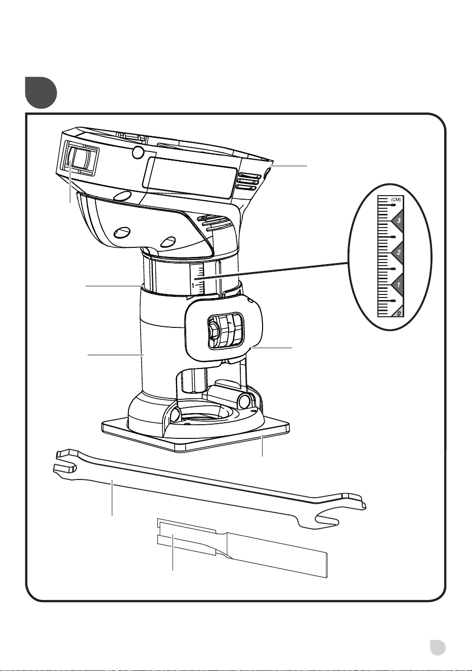
DESCRIPTION
1. Switch
2. Motor housing
3. Depth cut scale
4. Depth adjustment latch
5. Laminate sub-base
6. Base
7. Spindle lock button
8. Wrench
9. Router bit
10. Stop groove
11. Bit
12. Wrench on collet nut
13. To loosen
14. To tighten
15. Depress latches to remove battery pack
16. Battery pack
17. Latch
18. Right-handed use
19. Left-handed use
20. Off
21. On
22. Trimmer feed direction
23. Trim end grains first
24. Bit rotation
25. Guide outside
26. Thrust
27. Rotation
28. Feed
29. Guide
30. Guide inside
31. Indicator point(s)
32. Depth of cut scale
33. Too slow
34. Too fast
35. Depth of cut
36. Width of cut
37. 1st. pass
38. 2nd. pass
FEATURES
KNOW YOUR TRIMMER
See Figure 1.
The safe use of this product requires an understanding of
the information on the tool and in this operator’s manual
as well as a knowledge of the project you are attempting.
Before use of this product, familiarize yourself with all
operating features and safety rules.
Depth of cut scale
Your trimmer has an adjustable depth of cut scale on each
side of the tool.
Dual grip
Your trimmer is designed for either right-handed or left-
handed operation.
Laminate sub-base
The sub-base gives the operator greater visibility of the
workpiece during laminate trimming operations.
Spindle lock
The spindle lock button allows quick bit changes.
Switch
The ON/OFF switch is located on the back of the motor
housing, facing the operator.
ASSEMBLY
UNPACKING
This product has been shipped completely assembled.
■ Carefully remove the tool and any accessories from the
box. Make sure that all items listed in the packing list
are included.
■ Inspect the tool carefully to make sure no breakage or
damage occurred during shipping.
■ Do not discard the packing material until you have
carefully inspected and satisfactorily operated the tool.
■ If any parts are damaged or missing, please call your
service centre for assistance.
PACKING LIST
■ Trimmer
■ Collet/Latch adjustment wrench
■ Operator’s manual
WARNING
If any parts are missing do not operate this tool until the
missing parts are replaced. Failure to do so could result
in possible serious personal injury.
WARNING
Do not attempt to modify this tool or create accessories
not recommended for use with this tool. Any such
alteration or modication is misuse and could result
in a hazardous condition leading to possible serious
personal injury.
WARNING
To prevent accidental starting that could cause serious
personal injury, always remove the battery pack from the
tool when assembling parts.
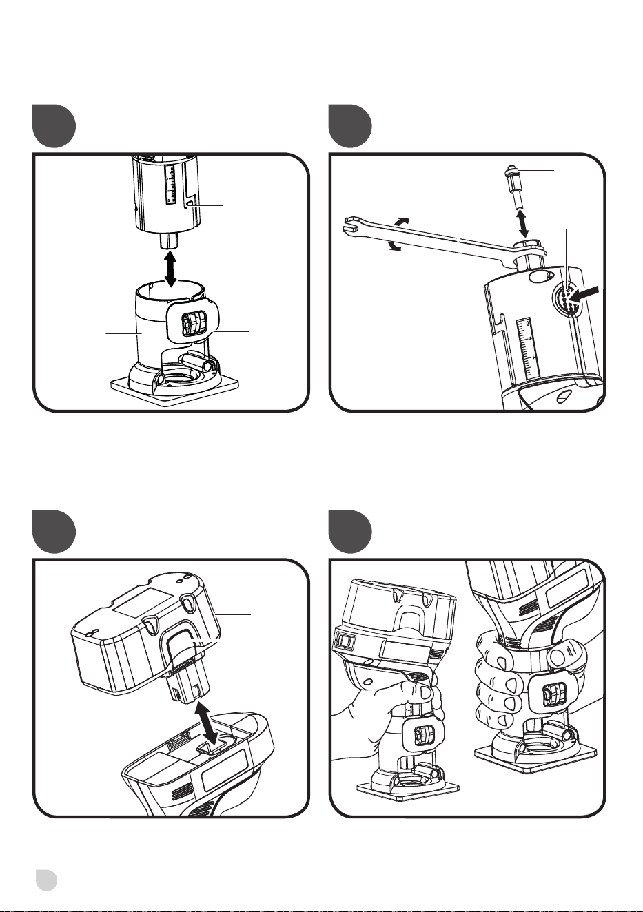
INSTALLING THE BATTERY PACK
See Figure 2.
NOTE: The battery pack is shipped in a low charge
condition. Therefore, it must be charged prior to use.
Refer to “CHARGING THE BATTERY PACK” for charging
instructions.
■ Place the battery pack in the trimmer. Align the raised
rib on the battery pack with the groove inside the
trimmer, then slide the battery pack into the trimmer.

8
WARNING
Always be sure the switch is in the OFF position before
installing the battery pack. Failure to do so could cause
accidental starting, leading to serious personal injury.
■ Make sure the latches on each side of your battery pack
snap into place and the battery pack is secured in the
trimmer before beginning operation.
CAUTION
When placing battery pack in the tool, be sure raised rib
on battery pack aligns with the bottom of the tool and
latches into place properly. Improper installation of the
battery pack can cause damage to internal components.
REMOVING THE BATTERY PACK
See Figure 2.
■ Locate the latches on the side of the battery pack and
depress them to release the battery pack from the
trimmer.
■ Turn the switch to OFF and remove the battery pack
from the trimmer.
WARNING
Battery tools are always in operating condition.
Therefore, switch should always be off and the battery
pack removed when not in use or carrying at your side.
ASSEMBLY
INSTALLING/REMOVING TRIMMING BITS
See Figures 3 - 4.
If installing the bit for the rst time, it can be installed once
the collet nut is loose. If changing bits, the bit will easily slip
from the collet after loosening the collet nut.
■ Turn the switch to OFF and remove the battery pack
from the trimmer.
■ Place the trimmer upside down on a workbench.
■ To remove the laminate sub-base assembly, open the
depth adjustment latch. Slide the base upward, then
left, then upward again to remove the base.
■ Depress the spindle lock button.
■ Use the wrench provided to turn the collet nut in a
counterclockwise direction. Continue to depress the
spindle lock button while loosening the collet nut.
■ With the trimmer still upside down on a workbench,
insert the shank of the bit into the collet. The shank of
the bit should be close to but not touching the bottom of
the collet. This allows for expansion when the bit gets
hot. A clearance of 1.6mm (1/16”) is adequate.
NOTE: The collet is machined to precision tolerances to t
bits with 6.35mm (1/4”) diameter shanks.
■ Hand-tighten the collet nut. Then, depress the spindle
lock button and continue tightening the collet nut
with the wrench provided by turning it in a clockwise
direction.
WARNING
If the collet nut is not tightened securely, the bit may
come out during use, causing serious personal injury.
■ Replace the laminate sub-base assembly by sliding it
onto the tool, along the grooves on the sides of the tool.
NOTE: Replace the base before using the trimmer. Do not
attempt to operate the trimmer without the base installed.
■ Close the depth adjustment latch.
■ Replace the battery pack.
WARNING
If you are changing a bit immediately after use, be careful
not to touch the collet nut, bit, or collet with your hands or
ngers. They will get burned because of the heat buildup
from cutting. Always use the wrench provided.
OPERATION
WARNING
Do not allow familiarity with tools to make you careless.
Remember that a careless fraction of a second is
sufcient to inict serious injury.
WARNING
Always wear safety goggles or safety glasses with side
shields when operating tools. Failure to do so could
result in objects being thrown into your eyes, resulting in
possible serious injury.
GRIPPING THE TRIMMER
See Figure 5.
The trimmer has a dual grip design that allows the operator
to hold the tool with either the right or left hand.
For right-handed operation, the depth adjustment latch
must be on the left side of the tool. For left-handed
operation, the depth adjustment latch must be on the right
side of the tool.
Always hold the trimmer so that the switch is facing you and
your thumb is positioned above the depth adjustment latch.
To change grip positions, remove the laminate sub-base
assembly (See “INSTALLING/REMOVING TRIMMING
BITS”). Position the base for right- or left-handed operation.
NOTE: Replace the base before using the trimmer. Do not
attempt to operate the trimmer without the base installed.

9
WARNING
Avoid hand positions that may expose ngers to bit
through open areas of trimmer base. Fingers entering
the opening in the trimmer base can be seriously cut or
burned.
CAUTION
To avoid damaging the motor from overheating, do not
let your hand cover the air vents.
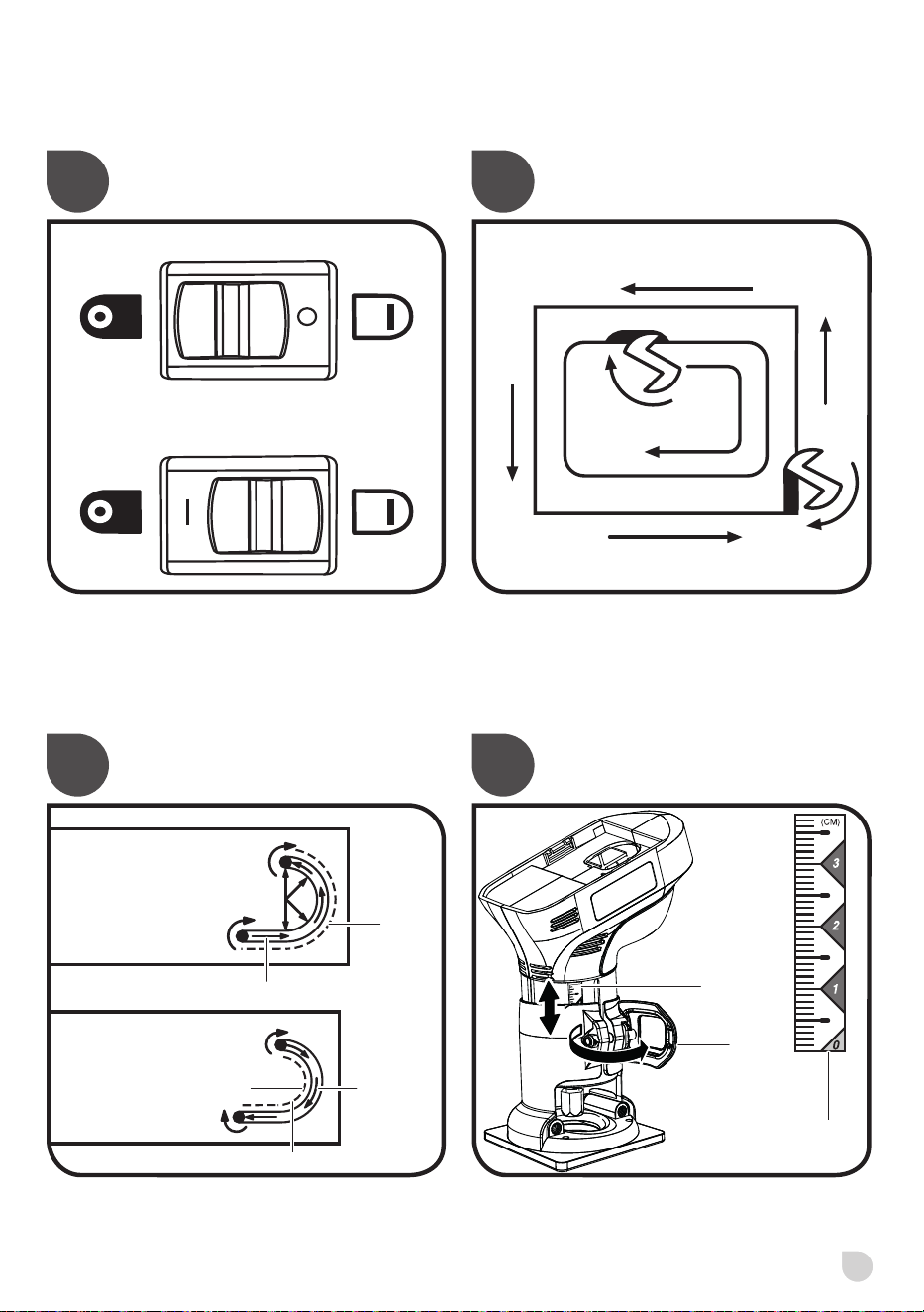
STARTING/STOPPING THE TRIMMER
See Figure 6.
To turn the trimmer ON (I), slide the switch on front of the
trimmer to the ON (I) position. Return the switch to the OFF
(O) position when nished.
OPERATING THE TRIMMER
Before starting the trimmer, with the battery pack
disconnected, make sure the bit is securely tightened in the
collet and that the depth of cut is properly set. Never start
the trimmer while the bit is in contact with the workpiece.
After completing a cut, pull the bit slightly away from the cut
surface. Turn the trimmer off and wait for the rotating bit to
completely stop before completely removing the tool from
the work surface.
When cutting, locate the base of the trimmer over the work
surface and rmly hold the body of the trimmer with your
hand. Make sure the trimmer is running at full speed before
contacting the workpiece.
DIRECTION OF FEED AND THRUST
See Figures 7 - 8.
The trimmer motor and bit revolve in a clockwise direction.
This gives the tool a slight tendency to twist in your hands
in a counterclockwise direction, especially when the motor
starts.
Feed the trimmer into the workpiece from left to right. When
fed from left to right, the rotation of the bit pulls the trimmer
against the workpiece. If fed in the opposite direction, the
rotation forces of the spinning bit will tend to throw the
trimmer away from the workpiece, causing kickback. This
could result in loss of control of the trimmer.
Because of the extremely high speed of bit rotation during
a proper feeding operation, there is very little kickback to
contend with under normal conditions. However, should the
bit strike a knot, hard grain, foreign object, etc. that would
affect the normal progress of the cutting action, there will
be a slight kickback. Kickback could be sufcient to spoil
the trueness of your cut if you are not prepared. Such a
kickback is always in the direction opposite the direction
of bit rotation.
To guard against kickback, plan your set-up and direction
of feed so that you will always be thrusting the tool—to hold
it against whatever you are using to guide the cut—in the
same direction that the leading edge of the bit is moving. The
thrust should be in a direction that keeps the sharp edges
of the bit continuously biting straight into new (uncut) wood.
SETTING DEPTH OF CUT
See Figure 9.
■ Turn the switch off and remove the battery pack from
the trimmer.
■ Open the depth adjustment latch as indicated by the
arrow.
■ Slide the motor housing section of the trimmer upward
until the tip of the bit reaches the work surface. The
depth of cut is zero at this point.
■ Adjust the position of the trimmer to obtain the desired
depth of cut by moving the motor housing section up or
down, as shown by the up/down arrow. The distance
the bit moves can be read on the depth of cut scale.
Each mark on the scale indicates a 1.6mm (1/16”)
change in depth setting. Indicator points are located on
the base.
■ Completely close the depth adjustment latch.
WARNING
Avoid open area of trimmer base. Serious personal
injury will result from contact with a rotating bit.
NOTE: To make deeper cuts, it is necessary to make as
many successive passes as required, lowering the bit
3.18mm (1/8”) for each new pass. To save time, perform all
the cutting necessary at one depth setting, then lower the
bit for the next pass. This will assure uniform depth when
the nal pass is completed.
WARNING
Do not use straight bits larger than 6.35mm (1/4”) or
edging bits which cut a pattern larger than 9.53mm (3/8”)
with this trimmer. Use of larger bits can result in loss of
control and serious personal injury.
WARNING
Never install a bit larger than the opening of the trimmer
base. The use of larger bits can result in loss of control
and possible serious personal injury.
WARNING
If the desired depth of cut is greater than can be safely
cut in one pass, make cuts in two or more passes. Do
not remove more than 3.18mm (1/8”) in a single pass.
Excessive depth of cut can result in loss of control and
the possibility of serious personal injury.
PROPER RATE OF FEED
Trimming and edge shaping depend upon careful set-up
and selecting the proper feed rate.
The proper feed rate is dependent upon:
■ The hardness and moisture content of the workpiece
■ The depth of cut. It is necessary that you do not exceed
3.18mm (1/8”) depth of cut for proper rate of feed.

10
■ The cutting diameter of the bit. Maximum bit size for
roundover and edging operations is 9.53mm (3/8”)
max. Maximum straight bit size for rabbeting and dado
operations is 6.35mm (1/4”).
For edge shaping in soft woods such as pine, a faster rate
of feed can be used. When edge shaping in hardwoods
such as oak, a slower rate of feed will be required. In all
wood types, a slower rate of feed is required when cutting
shallow grooves.
Several factors will help you select the proper rate of feed.
■ Choose a rate that does not slow down the trimmer
motor.
■ Choose the rate of feed at which the bit advances firmly
and surely to produce a continuous spiral of uniform
chips or a smooth trim edge on laminate.
■ Listen to the sound of the trimmer motor. A high-
pitched, strained sound means you are feeding too fast.
■ Check the progress of each cut. Too-slow feeding can
cause the trimmer to take off in a wrong direction from
the intended line of cut. Force-feeding increases the
strain of holding the tool and can result in damage to
the tool.
■ Notice the chips being produced as you cut. If the
trimmer is fed too slowly, it will scorch or burn the wood.
If the trimmer is fed too fast, it will take large chips out
of the wood and leave gouge marks.
Always test a cut on scrap piece of the workpiece wood
or laminate before you begin. Always grasp and hold the
trimmer rmly when trimming.
When using the largest recommended straight bit 6.35mm
(1/4”) in any type of wood, maintain a maximum cutting
depth of 3.18mm (1/8”) and a very slow feed rate to
achieve the best quality cut. A cross-grain cut requires a
slower pace than an identical cut with the grain in the same
workpiece.
There is no xed rule. Proper feed rate is learned through
practice and use.
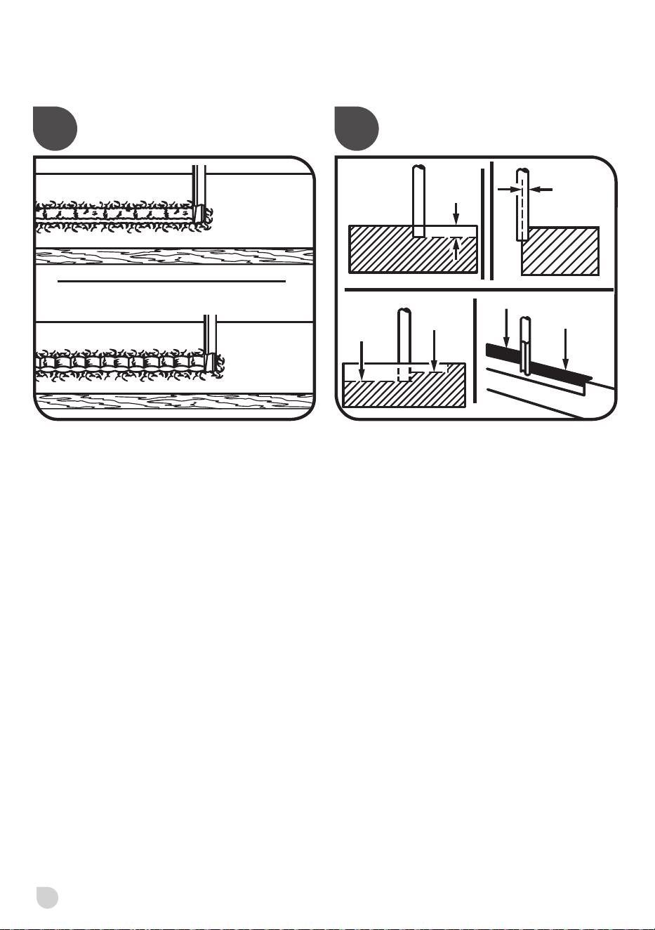
FORCE FEEDING
See Figure 10.
The trimmer is an extremely high-speed tool (29,000 min
-1
.),
and will make clean, smooth cuts if allowed to run freely without
the overload of a forced feed. Three things that cause force
feeding are bit size, depth of cut, and workpiece characteristics.
The larger the bit or the deeper the cut, the more slowly the
trimmer should be moved forward. If the wood is very hard,
knotty, gummy or damp, the operation must be slowed still
more.
Clean smooth trimming and edge shaping can be done
only when the bit is revolving at a relatively high speed and
is taking very small bites to produce tiny, cleanly-severed
chips. If the trimmer is forced to move forward too fast, the
speed of the bit becomes slower than normal in relation to
its forward movement. As a result, the bit must take bigger
bites as it revolves. Bigger bites mean bigger chips and a
rougher nish. Bigger chips also require more power, which
could result in overheating of the motor and lower battery
life.
Under extreme force-feeding conditions, the relative speed
of the bit can become so slow – and the bites it has to take
so large – that chips will be partially knocked off rather than
fully cut off. This will result in splintering and gouging of the
workpiece and will likely damage the tool.
TOO SLOW FEEDING
See Figure 10.
When the trimmer is advanced into the work too slowly
it scrapes away sawdust-like particles instead of cleanly
cutting into the workpiece. Scraping produces heat, which
can glaze, burn, or mar the cut, and can overheat the bit.
Dull bits can also contribute to scraping and burning.
It is more difcult to control a trimmer when the bit is
scraping instead of cutting. With practically no load on the
motor, the bit will be revolving near top RPM. When feeding
too slowly, the bit will have a greater than normal tendency
to bounce off the sides of the cut, especially if the wood has
a pronounced grain with hard and soft areas. The cut that
results may have rippled sides instead of straight.
DEPTH OF CUT
See Figure 11.
Depth of cut affects the rate of feed and the quality of a cut.
Using the proper depth of cut can lessen the possibility of
damage to the trimmer motor and bit.
A deeper cut requires a slower feed than a shallow one.
Making a cut that is too deep will slow the feed so that the
bit is scraping, rather than cutting, and is not recommended.
A too-deep cut can cause smaller bits to be broken off. bits
that are 1.6mm (1/16”) in diameter are easily broken off
when subjected to too much side thrust. A larger bit is not
as likely to break, but attempting a cut that is too deep may
result in a rough cut, and may make it difcult to guide and
control the bit as desired.
It is necessary that you do not exceed 3.18mm (1/8”) depth
of cut in a single pass, regardless of the bit size or the
softness or condition of the workpiece. This will result in a
higher quality cut.
To make deeper cuts, it is necessary to make as many
successive passes as required, lowering the bit 3.18mm
(1/8”) for each new pass. To save time, perform all the
cutting necessary at one depth setting, then lower the bit
for the next pass. This will assure uniform depth when the
nal pass is completed.
WARNING
If the desired depth of cut is greater than can be safely
cut in one pass, make cuts in two or more passes. Do
not remove more than 3.18mm (1/8”) in a single pass.
Excessive depth of cut can result in loss of control and
the possibility of serious personal injury.
11
MAINTENANCE
WARNING
When servicing, use only identical replacement parts.
Use of any other parts may create a hazard or cause
product damage.
WARNING
Always wear safety goggles or safety glasses with side
shields during power product operation or when blowing
dust. If operation is dusty, also wear a dust mask.
WARNING
To avoid serious personal injury, always remove
the battery pack from the product when cleaning or
performing any maintenance.
GENERAL MAINTENANCE
Avoid using solvents when cleaning plastic parts. Most
plastics are susceptible to damage from various types of
commercial solvents and may be damaged by their use.
Use clean cloths to remove dirt, dust, oil, grease, etc.
WARNING
Do not at any time let brake uids, gasoline, petroleum-
based products, penetrating oils, etc., come in contact
with plastic parts. Chemicals can damage, weaken or
destroy plastic which may result in serious personal
injury.
Only the parts shown on the parts list are intended to be
repaired or replaced by the customer. All other parts should
be replaced at an Authorized Service Center.
ENVIRONMENTAL PROTECTION
Recycle raw materials instead of disposing
of as waste. The machine, accessories
and packaging should be sorted for
environmental-friendly recycling.
SYMBOLS
Safety alert
Read the operator’s manual
Correct grip position
Waste electrical products should not
be disposed of with household waste.
Please recycle where facilities exist.
Check with your local authority or
retailer for recycling advice.

PRODUCT SPECIFICATIONS
Voltage 18 V
No load speed 29,000 min
-1
Switch Single speed
Collet size 6.35mm (1/4”)
BATTERY AND CHARGER
Compatible battery
pack (not included)
Compatible charger
(not included)
Lithium-Ion BPL-1820
BPL-1815
BPL18202PK
RB18L13
RB18L15
RB18L26
RB18L40
RB18LL40
BCL1418
BCS618
BCL14181H
BCL14183H
BCL1418IV*
Nickel Cadmium ABP1801G
ABP1802G
ABP-1813
ABP-1815
RB18N15
BCL1418
BCS618
ACR1800G
260022029
BCL14181H
BCL14183H
BCL1418IV*
* for vehicles with 12V DC outlets

Techtronic Industries (Australia) Pty. Ltd.
Level 1, 660 Doncaster Road
Doncaster, VIC 3108, Australia
Techtronic Industries New Zealand Ltd.
18-26 Amelia Earhart Avenue
Mangere, Auckland 2022, New Zealand
961152160-02