Owner's Guide Tools - Home Improvement
Quick Guide

- GFCI/EGFPD Test Button
- On/Off/GFCI/EGFPD Reset Button
Press to turn system ON
Hold to turn system OFF
Press to reset the GFCI/EGFPD
- The sensor cable shall be separated from power cables.
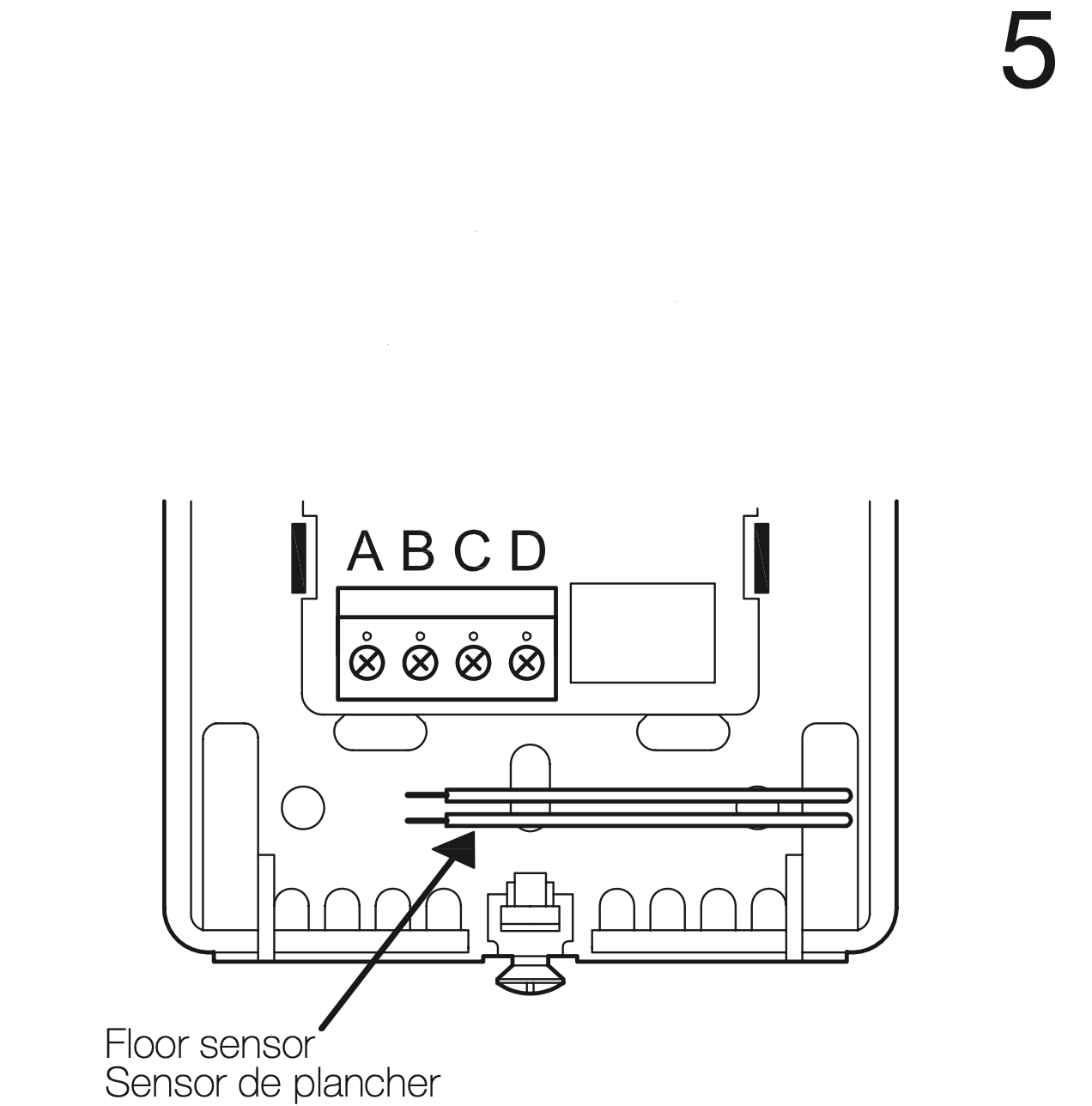
The floor sensor must be centered in between the heating cable.
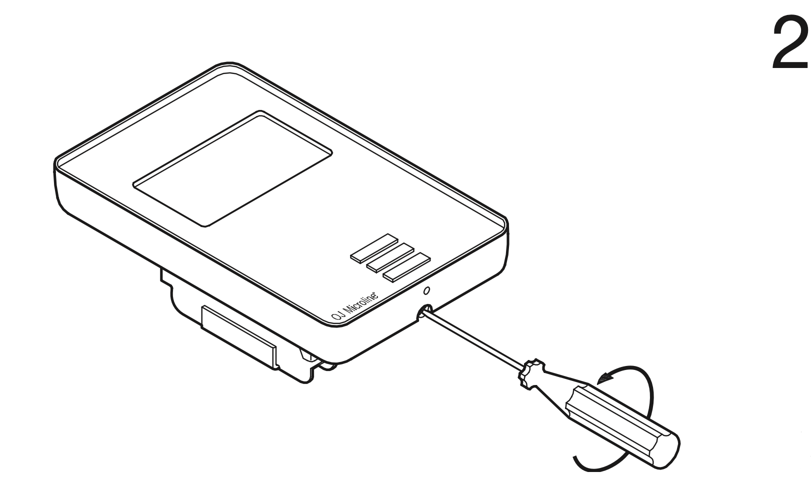
Loosen the screw at the bottom and remove the faceplate. Do not attempt to remove the screw completely.
Turn the power source OFF at the breaker panel.
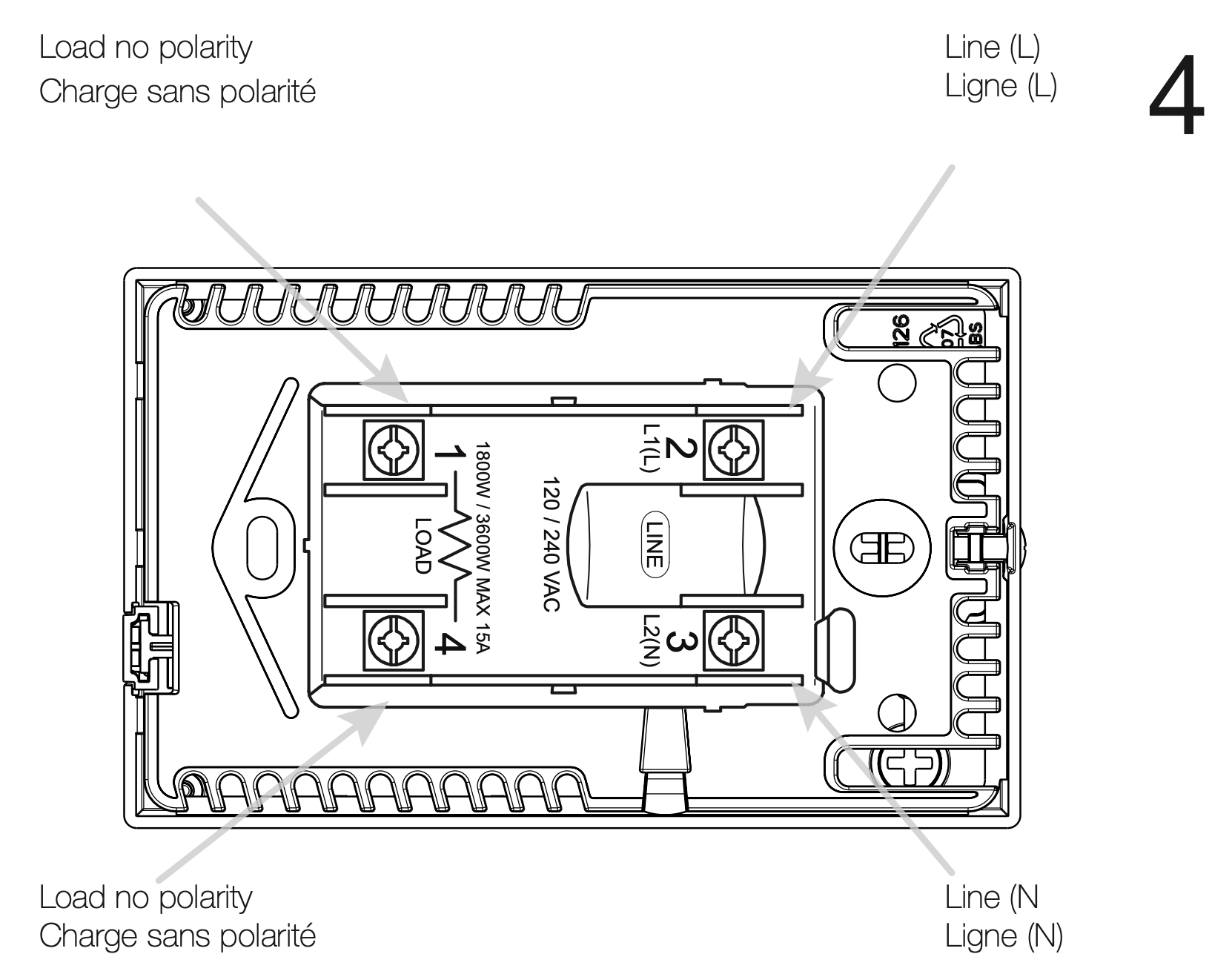
Make the electrical connections to the power base. See Warnings. AWG between 12 - 20 Note! Do not detach the screws from the terminals.
When fastening the screws use a torque between 0.8 - 1.2 Nm.
The floor sensor must not come in contact with electrical wires within the wall and must be routed outside the electrical box.
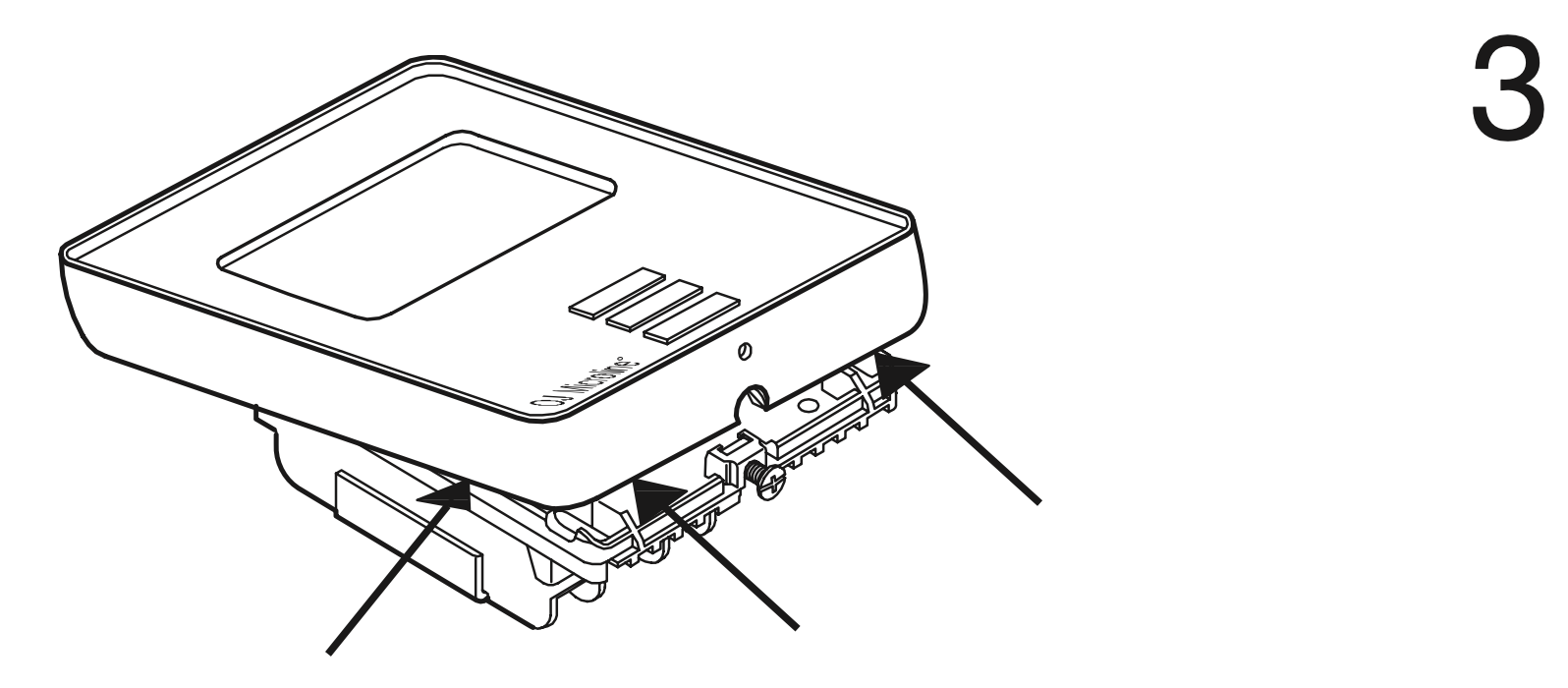
Thread the floor sensor cable through the hole in the power base.
Push the electrical wires to the back of the electrical box.

Push the power base into the electrical box.
Secure the power base to the wall.
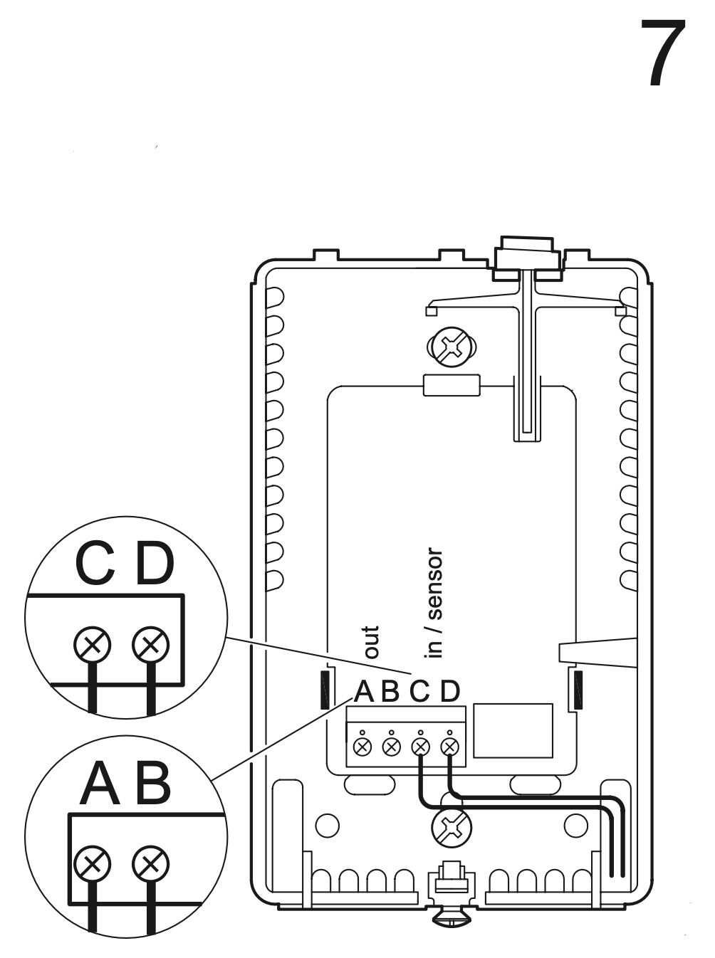
Make the sensor connections.
The Floor sensor has no polarity. Connect it to terminals C and D.
Expansion unit connects to termianals A and B*
*Refer to instructions included with expansion unit.
Checking the GFCI/EGFPD
It is important that the GFCI/EGFPD is checked for correct installation and function upon installation and monthly thereafter.
To check the GFCI/EGFPD:
Press the “TEST” button.
The test is successful if the red LED on the right of the thermostat flashes once every two seconds and “GROUND FAULT” appears on the display. If this does not occur, check the installation.
Press the “Standby/Reset” button to reset the GFCI/EGFPD.
The red LED will stop flashing and the display returns to its normal appearance.
If the test fails, repeat the test. If it continues to fail, ask an electrician to check the installation.
If, during normal operation, the GFCI/EGFPD trips without the “TEST” button being pressed, there could be a ground fault! To check whether it is a ground fault or nuisance tripping, press “Standby/Reset”. If this causes the red LED to stop flashing and stay off, it was nuisance tripping and the system is operating correctly. If this does not occur, there is a ground fault! In case of a ground fault, it is important to have the installation checked by a qualified electrician according to local and national regulations.
The red LED on the right of the thermostat can indicate four different GFCI/EGFPD states:
- LED off – NORMAL state.
- LED flashing slowly (once every two seconds) – TRIGGERED state. Try pressing the “Standby/Reset” button to reset the GFCI/EGFPD.
- LED flashing quickly (five flashes per second) – ERROR state. Try switching the power off and then back on again. If the thermostat re-enters the ERROR state, either the wiring is wrong (a GN exists) or the unit is defective and must be replaced.
- LED lit constantly – Internal microprocessor malfunction or abnormal fault in hardware! Try switching the thermostat off and then back on again. If the LED is still constantly lit, the GFCI/EGFPD is defective and the thermostat must be replaced.
Note: The LED lights up briefly without flashing during every power-up.
Basic Operation
Increasing/Decreasing the Temperature
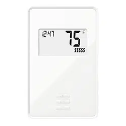
By default, the thermostat displays the CURRENT temperature. Press the Up/Down buttons ONCE to activate the backlight. Press the Up/Down buttons again to adjust the TARGET temperature between 41 to 104° F (5 to 40°C). The screen will display the TARGET temperature for ten seconds.
Setting the Time
- Press the Center button TWICE to access the Menu.
- Using the Up/Down buttons, go to 12/24 and press the Center button.
- Select the time format (12-hour clock or 24-hour clock) and press the Center button.
- Using the Up/Down buttons, go to TIME and press the Center button.
- Set the hour and press the Center button.
- Set the minutes and press the Center button.
- Using the Up/Down buttons, go to EXIT and press the Center button.
Changing the Temperature Unit
- Press the Center button TWICE to access the Menu.
- Using the Up/Down buttons, go to C/F and press the Center button.
- Select the temperature unit (Celsius or Fahrenheit) and press the Center button.
- Using the Up/Down buttons, go to EXIT and press the Center button.
Changing the Temperature Control Setting
- Press the Center button TWICE to access the Menu.
- Using the Up/Down buttons, go to FLOOR/ROOM and press the Center button.
- Select the temperature control setting and press the Center button.
- Using the Up/Down buttons, go to EXIT and press the Center button.
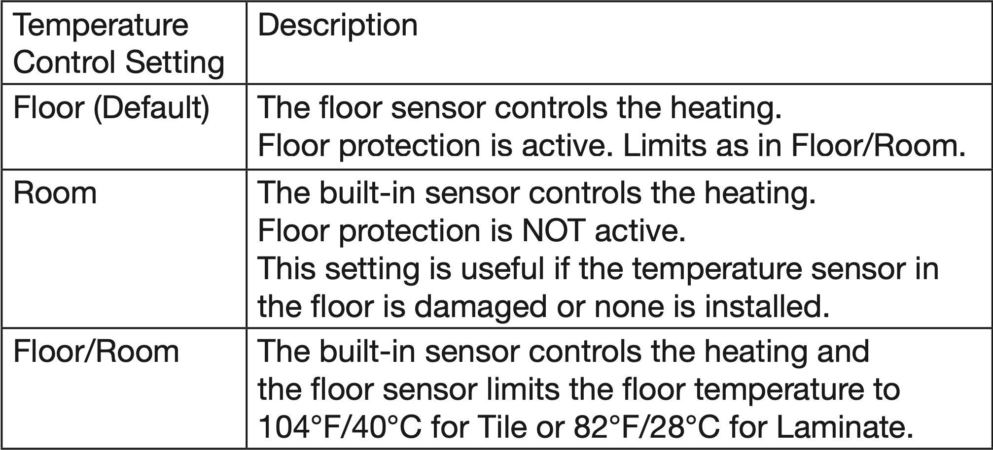
Changing the Floor Type (not selectable if the Temperature Control setting is set to ROOM – refer to ‘Changing Temperature Control Setting’ section). Tile is the default floor type.
- Press the Center button TWICE to access the Menu.
- Using the Up/Down buttons, go to TILE/LAMINATE and press the Center button.
A. TILE - the floor temperature will be limited to 104°F/40°C
B. LAMINATE - the floor temperature will be limited to 82°F/28°C.
- Select the floor type and press the Center button.
- Using the Up/Down buttons, go to EXIT and press the Center button.
Monitoring Usage
- Press the Center button TWICE to access the Menu.
- Using the Up/Down buttons, go to HISTORY and press the Center button.
A. The display will show the number of HOURS (denoted by the ’h’ on the right side of the screen) the floor heating system has been heating over the past 7 days. When done, press the Center button.
- Using the Up/Down buttons, go to EXIT and press the Center button.
Troubleshooting
E02 - This error message indicates a missing or damaged floor sensor. Flashing digits indicate that the measured floor temperature is higher than the limit temperature.
Heating is switched off.
Contact your installer to verify the floor sensor and connections.